

Page 1
Bulletin No. ITMA-E
Drawing No. LP0382
Released 04/13
Tel +1 (717) 767-6511
Fax +1 (717) 764-0839
www.redlion.net
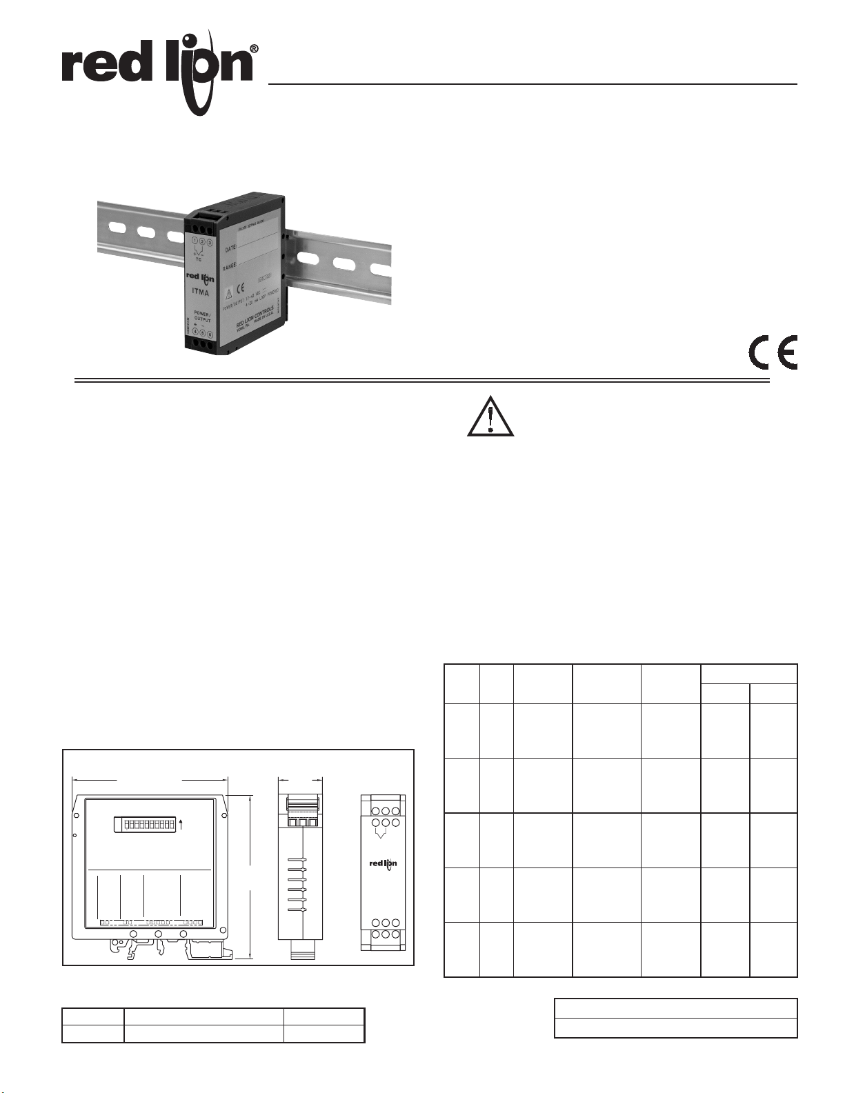
MODEL ITMA - INTELLIGENT THERMOCOUPLE MODULE WITH ANALOG OUTPUT
z USER PROGRAMMABLE INPUT
(THERMOCOUPLE TYPES J, K, T, & E, OR MILLIVOLT)
z 12 TO 42 VDC LOOP POWERED (4 TO 20 MA OUTPUT)
z MICROPROCESSOR CONTROLLED
z SIMPLE ADJUSTABLE RANGE SETTING (USING INPUT SIGNAL)
z THERMOCOUPLE BREAK DETECTION
z MOUNTS ON “T” AND “G” STYLE DIN RAILS
z 2-WAY ELECTRICAL ISOLATION (INPUT/OUTPUT & POWER)
z HIGH-DENSITY PACKAGING (22.5 MM WIDE)
z WIDE OPERATING TEMPERATURE RANGE
DESCRIPTION
The ITMA accepts a thermocouple or millivolt input and converts it into a 4
to 20 mA current output. The 4 to 20 mA output is linearly proportional to the
temperature or the millivolt input. This output is ideal for interfacing to
indicators, chart recorders, controllers, or other instrumentation equipment.
The ITMA is loop-powered which means that the same two wires are
carrying both the power and the output signal. The unit controls the output
current draw from 4 to 20 mA in direct proportion to the input change while
consuming less than 4 mA for power. The conversion to a current output signal
makes the ITMA less susceptible to noise interference and allows accurate
transmission over long distances. The 2-Way isolation allows the use of
grounded thermocouples which can provide additional noise reduction benefits.
The ITMA uses a ten position DIP switch to accomplish the input sensor
configuration, range selection, and unit calibration. A simple range setting
technique (Field Calibration) is used so the actual input signal adjusts the output
current for scaling. This technique eliminates the need for potentiometers which
are vulnerable to changes due to vibration.
The unit is equipped with a universal mounting foot for attachment to
standard DIN style mounting rails, including top hat rail (T) according to EN 50
022 - 35 × 7.5 and 35 × 15, and G profile according to EN 50 035 - G 32.
SAFETY SUMMARY
All safety related regulations, local codes and instructions that appear in the
manual or on equipment must be observed to ensure personal safety and to
prevent damage to either the instrument or equipment connected to it. If
equipment is used in a manner not specified by the manufacturer, the protection
provided by the equipment may be impaired.
DIMENSIONS In inches (mm)
.886
(22.5)
M2068B
123
+
TC
ITMA
POWER/
OUTPUT
+
456
-
-
RED LION CONTROLS
4
SWITCH
ICE POINT
YORK, PA.MADE IN U.S.A.
TEST
MODEL ITMA
1
0
ENABLED
DISABLED
3.11 (79.0)
31086579
FIELD CAL
BASIC CAL
OUTPUT CAL
1
5
0
UP
DOWN
OPEN SEN
421
ICE PT EN/DIS
867
TC TYPE
TC TYPE
OPEN SEN DN/UP
001001
000
J
M2069A
ON
RANGE
TC TYPE
TC TYPE
110
T
E
K
OFF = 0
RANGE
ON = 1
DIP SWITCH SETTINGS:
1011
01
10
9
0
0
111
1
2
0
MV
RANGE
3.30
(83.8)
3
ORDERING INFORMATION
MODEL NO. DESCRIPTION PART NUMBER
ITMA Intelligent Thermocouple Module ITMA2003
CAUTION: Read complete Instructions prior
to installation and operation of the unit.
SPECIFICATIONS
1. POWER: 12 to 42 VDC *(Loop powered). The power supply must have a
30 mA min. capacity.
[* Min. voltage must be increased to include the drop across any current
display indicator]
2. INPUT: J, K, T, E, mV [selectable via DIP switch]
3. OUTPUT: Loop powered (passive), 4 to 20 mA Linear output
Ripple: Less than 15 mV peak-to-peak max., across 250Ω load resistor (up
to 120 Hz frequencies).
4. RANGE & ACCURACY: (12 Bit resolution)
Accuracy: ± ( 0.075% Range + 0.25°C [Conformity] + 0.50°C [Ice Point])
at 23°C after 20 min. warm-up, conforming to ITS-90.
Note: TC Conformity and Ice Point do not apply to mV input.
Relative Humidity: Less than 85% RH (non-condensing)
Span: The input span can be set to a min. of 1/8 of the full scale range,
anywhere within that range.
Thermocouple Accuracy for each type and the corresponding ranges:
RANGE
DIP SWITCH
TYPE RANGE
6 7 8 9 10
TEMPERATURE
& mV RANGE
RANGE
ACCURACY
TC
(INPUT)
0 0 0 0 0 0 -136 to 111°C ± 0.19°C
1 0 0 0 0 1 69 to 575°C ± 0.38°C
2 0 0 0 1 0J338 to 800°C ± 0.35°C
3 0 0 0 1 1 -149 to 862°C ± 0.76°C
0 0 0 1 0 0 -200 to 541°C ± 0.56°C
1 0 0 1 0 1 427 to 1132°C ± 0.53°C
K
2 0 0 1 1 0 648 to 1372°C ± 0.54°C
3 0 0 1 1 1 -192 to 1372°C ± 1.17°C
0 0 1 0 0 0 -225 to 149°C ± 0.28°C
1 0 1 0 0 1 74 to 326°C ± 0.19°C
T
2 0 1 0 1 0 68 to 400°C ± 0.25°C
3 0 1 0 1 1 -200 to 400°C ± 0.45°C
0 0 1 1 0 0 -111 to 311°C ± 0.32°C
1 0 1 1 0 1 276 to 609°C ± 0.25°C
E
2 0 1 1 1 0
3 0 1 1 1 1
0 -9 to 6 mV ± 0.0113 mV
1 1 1 0 0
1 1 1 1 0 1 -9 to 22 mV ± 0.0233 mV
mV
2 1 1 1 1 0 -9 to 63 mV ± 0.0540 mV
377 to 1000°C ± 0.47°C
-114 to 1000°C ± 0.84°C
3 1 1 1 1 1 -9 to 77 mV ± 0.0645 mV
Note: DIP switch settings ON = 1 OFF = 0
Accuracy Example:
Type “J” Range “0”
-136°C to 111°C
Range
( ±0.19°C + ±0.25°C + ±0.50°C ) = ±0.94°C
Conformity
WIRE COLOR
BS1843ANSI
White (+)
Red (-)
Yellow (+)
Red (-)
Blue (+)
Red (-)
Violet (+)
Red (-)
Yellow (+)
Blue (-)
Brown (+)
Blue (-)
White (+)
Blue (-)
Brown (+)
Blue (-)
N/AN/A
Ice Point Total Error
1
Page 2
5. TC BREAK DETECTION: Upscale to 22.5 mA (nominal) or Downscale to
3.6 mA (nominal) [selectable via DIP switch]
6. RESPONSE TIME: 400 msec (to within 99% of final value w/step input;
typically, response is limited to response time of probe.)
7. ENVIRONMENTAL CONDITIONS:
Operating Temperature Range: -25°C to 75°C (-13°F to 167°F)
Storage Temperature Range: -40°C to 85°C (-40°F to 185°F)
Operating and Storage Humidity: 85% max. (non-condensing) from -25°C
to 75°C.
Vibration to IEC 68-2-6: Operational 5-150 Hz, 2 g
Shock to IEC 68-2-27: Operational 30 g
Temperature Coefficient: ± 0.01% of input range per °C
Ice Point Compensation: ± 0.75°C for a 50°C change in temperature
Altitude: Up to 2000 meters.
8. DIELECTRIC WITHSTAND VOLTAGE: 1500 VAC for 1 minute, at 50
VAC working volts, from Input to Output
9. CERTIFICATIONS AND COMPLIANCES:
CE Approved
EN 61326-1 Immunity to Industrial Locations
Emission CISPR 11 Class A
IEC/EN 61010-1
Refer to the EMC Installation Guidelines section of this bulletin for
additional information.
10. MOUNTING: Universal mounting foot for attachment to standard DIN
style mounting rails, including top hat (T) profile rail according to EN50022
- 35 × 7.5 and 35 × 15, and G profile rail according to EN50035 - G32.
11. CONNECTION: Compression type terminal block
12. CONSTRUCTION: High impact black plastic case. Installation Category I,
Pollution Degree 2.
13. WEIGHT: 2.7 oz (76.54 g)
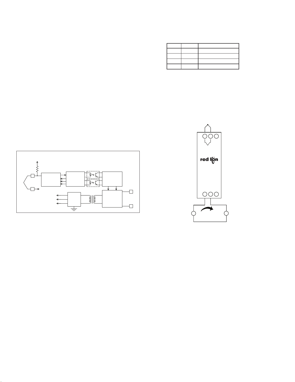
BLOCK DIAGRAM
3V
FACTORY SETTINGS
The unit is shipped from the factory calibrated for a 4 to 20 mA output using
a type J thermocouple in range 3. The ITMA should be Field calibrated by the
operator for the application environment it will be used in. If the unit is not
recalibrated by the operator, the following table lists the temperature ranges for
the given thermocouple types.
TYPE RANGE TEMPERATURE RANGE
J 3 -50°C to 500°C
K 3 -85°C to 790°C
T 3 -195°C to 162°C
E 3 3°C to 602°C
WIRING CONNECTIONS
All conductors should meet voltage and current ratings for each terminal.
Also, cabling should conform to appropriate standards of good installation,
local codes and regulations. It is recommended that power supplied to the unit
be protected by a fuse or circuit breaker. When wiring the unit, use the numbers
on the label to identify the position number with the proper function. Strip the
wire, leaving approximately 1/4" (6 mm) of bare wire exposed (stranded wire
should be tinned with solder). Insert the wire into the terminal, and tighten the
screw until the wire is clamped tightly.
TC
1-2 3
+
TC
22M
PWM
CONTROL
CIRCUITRY
LOOP
POWER
CIRCUITRY
4
POWER/
OUTPUT
5
TC
1
+
2
A/D
CONVERTER
1.7V
4V
3V
1.7V
PROCESS
CIRCUITRY
POWER
SUPPLY
FUNCTION DESCRIPTIONS
Open Sensor Detection
The output can be set to go Upscale or Downscale for the detection of an
open sensor. The Upscale setting makes the output go to 22.5 mA (nominal).
The Downscale setting makes the output go to 3.5 mA (nominal). This setting
is always active, so changes in the setting are effective immediately.
Ice Point Compensation
The Ice Point Compensation for the thermocouple sensors can be enabled (DIP
Switch OFF) or disabled (DIP Switch ON). The mV sensor input is not affected
by this setting. Generally, the Ice Point Compensation is always enabled.
Calibration Malfunction
If the unit has scaling problems (current remains at 3.5 mA nominal), check
the voltage between the TC- Input (-) and TEST pad (+) [located next to the DIP
switches on the side of the unit]. For normal operation the voltage is -1.77 V
(nominal). If the voltage is +1.23 V(nominal), a problem occurred storing
information in the E2PROM. When this happens, perform a Basic Calibration
and then a Field Calibration. Turn off power for 5 seconds. Turn on power and
check the voltage between the TEST pad (+) and TC- Input (-). If the voltage is
still +1.23 V(nominal), contact the factory.
ITMA
POWER/
OUTPUT
M2068B
+
4 5-6
12 to 42 VDC
Power Supply
±
4 to 20 mA
Current Display
Indicator or
A
Monitoring
Instrument
EMC INSTALLATION GUIDELINES
Although Red Lion Controls Products are designed with a high degree of
immunity to Electromagnetic Interference (EMI), proper installation and wiring
methods must be followed to ensure compatibility in each application. The type
of the electrical noise, source or coupling method into a unit may be different
for various installations. Cable length, routing, and shield termination are very
important and can mean the difference between a successful or troublesome
installation. Listed are some EMI guidelines for a successful installation in an
industrial environment.
1. A unit should be mounted in a metal enclosure, which is properly connected
to protective earth.
2. Use shielded cables for all Signal and Control inputs. The shield connection
should be made as short as possible. The connection point for the shield
depends somewhat upon the application. Listed below are the recommended
methods of connecting the shield, in order of their effectiveness.
a. Connect the shield to earth ground (protective earth) at one end where the
unit is mounted.
b. Connect the shield to earth ground at both ends of the cable, usually when
the noise source frequency is over 1 MHz.
3. Never run Signal or Control cables in the same conduit or raceway with AC
power lines, conductors, feeding motors, solenoids, SCR controls, and
heaters, etc. The cables should be run through metal conduit that is properly
grounded. This is especially useful in applications where cable runs are long
and portable two-way radios are used in close proximity or if the installation
is near a commercial radio transmitter. Also, Signal or Control cables within
an enclosure should be routed as far away as possible from contactors,
control relays, transformers, and other noisy components.
4. Long cable runs are more susceptible to EMI pickup than short cable runs.
2
Page 3
5. In extremely high EMI environments, the use of external EMI suppression
devices such as Ferrite Suppression Cores for signal and control cables is
effective. The following EMI suppression devices (or equivalent) are
recommended:
Fair-Rite part number 0443167251 (RLC part number FCOR0000)
Line Filters for input power cables:
Schaffner # FN2010-1/07 (Red Lion Controls # LFIL0000)
6. To protect relay contacts that control inductive loads and to minimize radiated
and conducted noise (EMI), some type of contact protection network is
normally installed across the load, the contacts or both. The most effective
location is across the load.
a. Using a snubber, which is a resistor-capacitor (RC) network or metal oxide
varistor (MOV) across an AC inductive load is very effective at reducing
EMI and increasing relay contact life.
b. If a DC inductive load (such as a DC relay coil) is controlled by a transistor
switch, care must be taken not to exceed the breakdown voltage of the
transistor when the load is switched. One of the most effective ways is to
place a diode across the inductive load. Most RLC products with solid
state outputs have internal zener diode protection. However external diode
protection at the load is always a good design practice to limit EMI.
Although the use of a snubber or varistor could be used.
RLC part numbers: Snubber: SNUB0000
Varistor: ILS11500 or ILS23000
7. Care should be taken when connecting input and output devices to the
instrument. When a separate input and output common is provided, they
should not be mixed. Therefore a sensor common should NOT be connected
to an output common. This would cause EMI on the sensitive input common,
which could affect the instrument’s operation.
Visit RLC’s web site at http://www.redlion.net/Support/InstallationConsiderations.
html for more information on EMI guidelines, Safety and CE issues as they
relate to Red Lion Controls products.
INPUT AND POWER/OUTPUT CONNECTIONS
Input
When connecting the thermocouple, be certain that the connections are clean
and tight. The negative thermocouple lead is connected to Terminal #2 (TC-)
and the positive lead is connected to Terminal #1 (TC+). If the thermocouple
probe cannot be connected directly to the module, thermocouple wire or
thermocouple extension-grade wire must be used to extend the connection points
(copper wire does not work). Always refer to the thermocouple manufacturer’s
recommendations for mounting, temperature range, shielding, etc.
Power/Output
The unit has the power and current output sharing the same two wires (looppowered). Connect DC power to terminals #4 and #5, observing the correct
polarity, with a current meter/indicator connected in between so that the output
current can be monitored. Be certain that the DC power is relatively “clean”
and within the 12 to 42 VDC range at the terminals. The current meter voltage
drop must be included in power supply considerations.
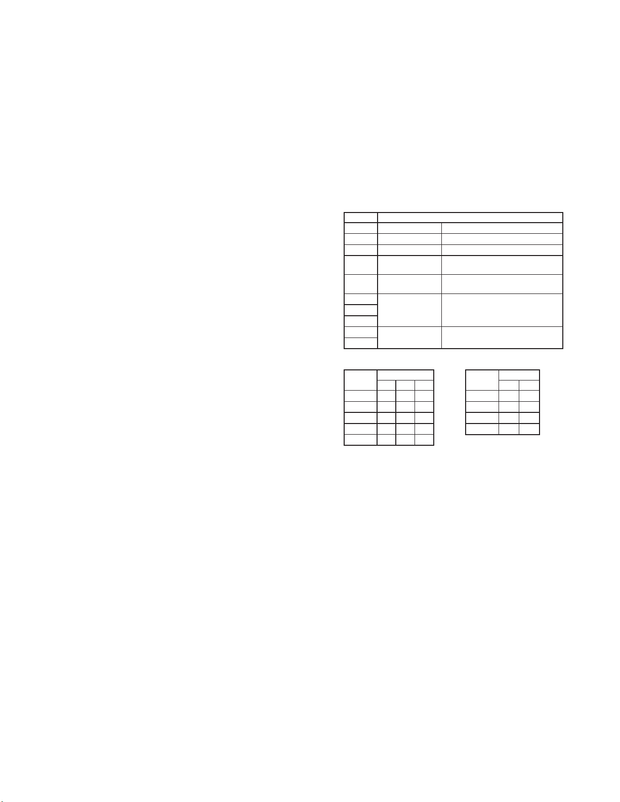
DIP SWITCH SETTING DESCRIPTIONS
SWITCH DESCRIPTION
1 OUTPUT CAL Output Calibration
2 FIELD CAL Field Calibration
3 BASIC CAL Basic Calibration
4 ICE PT EN/DIS
OPEN SEN DN/UPOpen Sensor Detection -
5
6
7
8
9
10
TC TYPE
RANGE
Ice Point Compensation -
Disabled (ON) / Enabled (OFF)
Upscale (ON) / Downscale (OFF)
Thermocouple Type - 3 switch
combination setting
Sensor Range - 2 switch
combination setting
TC Type and Range switch settings (ON = 1 OFF = 0)
TC TYPE
mV 1 1 1
DIP SWITCH
6 7 8 9 10
J 0 0 0 0 0 0
K 0 0 1 1 0 1
T 0 1 0 2 1 0
E 0 1 1 3 1 1
RANGE
DIP SWITCH
3
Page 4

1 65432
10
987
1 65432
10
987
1 65432
10
987
1 65432
10
987
1 65432
10
987
1.0 Field Calibration
1 65432
10
987
1 65432
10
987
1 65432
10
987
1 65432
10
987
4123ON65 789
10
123456789
10
CALIBRATION PROCEDURES
Thermocouple
12 to 42 VDC
Power Supply
±
Field Calibration Wiring
RED LION CONTROLS
YORK, PA.
MADE IN U.S.A.
MODEL ITMA
TEST
OUTPUT CAL
FIELD CAL
BASIC CAL
ICE PT EN/DIS
OPEN SEN DN/UP
TC TYPE
TC TYPE
TC TYPE
RANGE
RANGE
ON
DIP SWITCH SETTINGS:
ON = 1 OFF = 0
Calibrator
+
-
21 3
+
-
TC
ITMA
POWER/
OUTPUT
M2068B
+
4 5-6
4 to 20 mA
1
2
4
5
6
7
8
9
10
M2069A
Current Display
A
Indicator
Test
Pad
Step 1.3 & 1.4
Step 1.5
1 65432
Step 1.7
Step 1.9
1 65432
Step 1.11
Step 1.13
Step 1.14
Field Calibration scales the 4 to 20 mA output to a temperature or mV input. This
procedure assigns an input value to 4 mA and an input value to 20 mA. The
microprocessor handles configuring the output so it is linear to the temperature or mV
ON
input. The Field Calibration procedure is described below.
Note: Allow a 30 minute warm-up period before calibrating. The unit needs to have the
Field Calibration completed by the operator before normal operation. To abort this
calibration and reset to the previous settings, set the FIELD CAL switch OFF prior to
ON
the final OFF setting of the OUTPUT CAL switch (Step 1.13) and turn off power. Wait
5 seconds and then turn on power and the previous settings will be loaded.
10
987
Field Calibration with a Thermocouple Calibrator
1.1 Enable the Ice Point Compensation on the Thermocouple Calibrator and set it to the
ON
Thermocouple type being used in your application.
1.2 Connect the thermocouple wire as selected in step 1 to the TC input terminals of the
ITMA and the thermocouple calibrator.
1.3 Set the ICE PT EN/DIS switch (#4) OFF to enable Ice Point Compensation.
1.4 Set the Type and Range for the thermocouple or mV used in your application
ON
(DIP switches #6 through #10). (TC type “J”, Range 0 shown)
1.5 Set the FIELD CAL switch (#2) ON. [Current goes to 3.6 mA (nominal)]
10
987
1.6 Apply the input signal for the 4 mA output.
1.7 Set the OUTPUT CAL switch (#1) ON. [Current stays at 3.6 mA (nominal)]
ON
1.8 Adjust the input signal up until the output equals 4 mA.
1.9 Set the OUTPUT CAL switch (#1) OFF. [Current increases to 22.3 mA (nominal)]
1.10 Apply the input signal for the 20 mA output.
ON
1.11 Set the OUTPUT CAL switch (#1) ON. [Current decreases to 20.5 mA (nominal)]
1.12 Adjust the input signal down until the output equals 20 mA.
1.13 Set the OUTPUT CAL switch (#1) OFF.
1.14 Set the FIELD CAL switch (#2) OFF.
ON
1.15 Disconnect the thermocouple calibrator from the ITMA and connect the actual
sensor to be used in the application.
2.0 Field Calibration With an Accurate Adjustable Millivolt Source: (Alternate Method)
Adjustable
12 to 42 VDC
Power Supply
±
Field Calibration Wiring
RED LION CONTROLS
YORK, PA.
MADE IN U.S.A.
MODEL ITMA
TEST
OUTPUT CAL
FIELD CAL
BASIC CAL
ICE PT EN/DIS
OPEN SEN DN/UP
TC TYPE
TC TYPE
TC TYPE
RANGE
RANGE
ON
DIP SWITCH SETTINGS:
ON = 1 OFF = 0
Millivolt
Source
+-
1 2
+
TC
ITMA
POWER/
OUTPUT
M2068B
+
4 5
4 to 20 mA
1
2
4
5
6
7
8
9
10
-
M2069A
Step 2.2 & 2.3
3
Step 2.4
1 65432
Step 2.6
Step 2.8
10
987
-
6
Current Display
A
Indicator
Step 2.10
Test
Pad
Step 2.12
123456789
10
Step 2.13
This calibration procedure can be used to assign the high and low input values if a
ON
thermocouple calibrator is not available.
Note: To abort this calibration and reset to the previous settings, set the FIELD CAL
switch OFF prior to the final OFF setting of the OUTPUT CAL switch (Step 2.12) and
turn off power. Wait 5 seconds and then turn on power and the previous settings will
ON
be loaded.
2.1 Connect the accurate Adjustable Millivolt Source to the TC input terminals.
2.2 Set the ICE PT EN/DIS switch (#4) ON to disable Ice Point Compensation.
ON
2.3 Set the Type and Range for the thermocouple or mV used in your application
(DIP switches #6 through #10).(TC type “J”, Range 0 shown)
2.4 Set the FIELD CAL switch (#2) ON.[Current goes to 3.6 mA (nominal)]
2.5 Apply the input signal (mV equivalent for the thermocouple temperature) for the 4
ON
mA output.
2.6 Set the OUTPUT CAL switch (#1) ON. [Current stays at 3.6 mA (nominal)]
2.7 Adjust the input signal up until the output equals 4 mA.
2.8 Set the OUTPUT CAL switch (#1) OFF. [Current increases to 22.3 mA (nominal)]
ON
2.9 Apply the input signal (millivolt equivalent for the thermocouple temperature) for
the 20 mA output.
2.10 Set the OUTPUT CAL switch (#1) ON. [Current decreases to 20.5 mA (nominal)]
2.11 Adjust the input signal down until the output equals 20 mA.
ON
2.12 Set the OUTPUT CAL switch (#1) OFF.
2.13 Set the FIELD CAL switch (#2) OFF.
ON
2.14 Set the ICE PT EN/DIS switch (#4) OFF to enable Ice Point Compensation.
2.15 Disconnect millivolt source from the ITMA and connect the actual sensor to be used
in the application.
4
Step 2.14
Page 5

1 234567 98
10
1 234567 98
10
1234567 98
10
3.0 Ice Point Calibration
Adjustable
Millivolt
Source
+-
1 2 3
+
-
TC
ITMA
POWER/
OUTPUT
M2068B
+
4 5-6
12 to 42 VDC
Power Supply
±
4 to 20 mA
Ice Point Calibration Wiring
RED LION CONTROLS
YORK, PA.
MADE IN U.S.A.
MODEL ITMA
TEST
OUTPUT CAL
FIELD CAL
BASIC CAL
ICE PT EN/DIS
OPEN SEN DN/UP
TC TYPE
TC TYPE
TC TYPE
DIP SWITCH SETTINGS:
ON = 1 OFF = 0
RANGE
RANGE
1
2
4
5
6
7
8
9
10
ON
M2069A
Thermometer
Current Display
A
Indicator
Test
Pad
Precision
Step 3.1
1 234567 98
Step 3.5
Step 3.5
Step 3.6
The Ice Point Calibration should only be performed with an ambient temperature
between 21°C and 29°C. This Calibration was performed on the unit at the factory during
the Basic Calibration and generally does not need to be done again. The Ice Point
Compensation can be adjusted through this calibration. The Ice Point Calibration
procedure is described below.
Note: Calibration can be aborted by setting the BASIC CAL switch OFF prior to the
setting of the OUTPUT CAL switch OFF. (Step 3.6)
3.1 Connect a precision mV source with an accuracy of 0.02% to Terminal #1 TC+ Input
and Terminal #2 TC- Input. Set the OUTPUT CAL switch (#1) and ICE PT EN/DIS
switch (#4) OFF. Set the BASIC CAL (#3) and FIELD CAL (#2) switches ON. The
ON
positions of switches #5 thru #10 are not relevant for this calibration procedure.
3.2 Connect a precision thermometer (accuracy of 0.1°C) to the unused terminal (#3)
beside the TC Input terminals.
3.3 Apply power and allow a 30 minute warm-up period. [Current goes to 3.5 mA
(nominal)]
3.4 Using the temperature indicated by the precision thermometer, input an equivalent
10
1 mV/°C signal to the TC Input terminals and wait 5 seconds.
ON
3.5 Set the OUTPUT CAL switch (#1) ON and then OFF.
ON
3.6 Set the BASIC CAL switch (#3) and FIELD CAL switch (#2) OFF. [Current
increases to 3.6 mA (nominal) or more]
ON
5
Page 6

1234567 98
10
1234567 98
10
312 54 6789
10
4.0 Basic Calibration
Adjustable
Millivolt
Source
ITMA
M2068B
12 to 42 VDC
Power Supply
±
4 to 20 mA
Basic Calibration Wiring
RED LION CONTROLS
YORK, PA.
MADE IN U.S.A.
MODEL ITMA
TEST
OUTPUT CAL
FIELD CAL
BASIC CAL
ICE PT EN/DIS
OPEN SEN DN/UP
TC TYPE
TC TYPE
TC TYPE
RANGE
RANGE
ON
DIP SWITCH SETTINGS:
ON = 1 OFF = 0
+-
1 2 3
+
-
TC
POWER/
OUTPUT
+
4 5-6
1
2
4
5
6
7
8
9
10
M2069A
Thermometer
Current Display
A
Indicator
Test
Pad
Precision
1234567 98
Step 4.1
1 234567 98
1234567 98
Steps 4.3 to 4.15
Step 4.16
21ON43 56789
Step 4.17
Step 4.18
The Basic Calibration should only be performed with an ambient temperature
between 21°C and 29°C. The Basic Calibration was performed on the unit at the
factory and generally does not need to be done again. This procedure initializes the
unit by calibrating the input, and the Ice Point Compensation. The Basic Calibration
should be performed only if a condition exists as described in the “Calibration
Malfunction” section. After completion of this calibration, the unit needs to be scaled
in Field Calibration. The Basic Calibration procedure is described below.
Note: To abort this calibration and reset to the previous settings, set the BASIC CAL
switch OFF prior to the final setting of the OUTPUT CAL switch (Step 4.17) and
turn off power for 5 seconds. Then turn on power and the previous settings will be
10
loaded.
4.1 Connect a precision mV source with an accuracy of 0.02% to Terminal #1 (TC+
ON
Input) and Terminal #2 (TC- Input). Set the ICE PT EN/DIS switch (#4), RANGE
(#9
), TYPE (#6, #7, and #8), OUTPUT CAL (#1), and FIELD CAL (#2)
switches OFF. Set the BASIC CAL switch (#3) ON.
4.2 Apply power and allow a 30 minute warm-up period. [Current goes to 3.5 mA
(nominal)]
4.3 Set the OUTPUT CAL switch (#1) ON and then OFF.
10
10
4.4 Input -9 mV and wait 5 seconds.
4.5 Set the OUTPUT CAL switch (#1) ON and then OFF.
ON
4.6 Input 6 mV and wait 5 seconds.
4.7 Set the OUTPUT CAL switch (#1) ON and then OFF.
4.8 Input 22 mV and wait 5 seconds.
ON
4.9 Set the OUTPUT CAL switch (#1) ON and then OFF.
4.10 Input 41mV and wait 5 seconds.
4.11 Set the OUTPUT CAL switch (#1) ON and then OFF.
4.12 Input 63 mV and wait 5 seconds.
4.13 Set the OUTPUT CAL switch (#1) ON and then OFF.
4.14 Input 77 mV and wait 5 seconds.
ON
4.15 Set the OUTPUT CAL switch (#1) ON and then OFF.
4.16 Ice Point Calibration.
10
a. If ice point calibration is not desired, go to step 4.17.
b. To Enable ice point calibration, set the FIELD CAL switch (#2) ON.
1. Connect a precision thermometer (accuracy of 0.1°C) to the unused
terminal beside the TC Input terminals.
ON
2. Allow 5 minutes for the temperature to equalize.
3. Using the temperature indicated by the precision thermometer, input an
equivalent 1 mV/°C signal to the TC Input terminals.
4.17 Set the OUTPUT CAL switch (#1) ON and then OFF.
ON
4.18 Set the BASIC CAL switch (#3) and FIELD CAL switch (#2) OFF. [Current
increases to 3.6 mA (nominal) or more]
4.19 Perform a Field Calibration. (See Section 1.0)
6
Page 7

INSTALLATION
The unit is equipped with a universal mounting foot for attachment to standard DIN style mounting rails, including
G profile rail according to EN50035 - G32 , and top hat (T) profile rail according to EN50022 - 35 x 7.5 and 35 x 15.
The unit should be installed in a location that does not exceed the maximum operating temperature and provides good
air circulation. Placing the unit near devices that generate excessive heat should be avoided.
To install the
ITMA on a “G” style
DIN rail, angle the
module so that the
upper groove of the
“foot” catches under
the lip of the top rail.
Push the module
toward the rail until it
snaps into place. To
remove a module
from the rail, push up
on the bottom of the
module while pulling
out away from the
rail.
PROCESS
AREA BEING
MONITORED
VAC
(~) N12
PSDR1200
IN
TC
~
~
-
-
Fuse 125mA
G Rail Installation
1-2 3
+
TC
ITMA
24VDC (+)(~) L1
OUT
GND (-)
MC2021X
3
4
POWER/
OUTPUT
M2068B
+
4 5-6
4 to 20 mA
+
-
CHART
RECORDER
To install the ITMA
T Rail Installation
on a “T” style rail,
angle the module so
that the top groove of
the “foot” is located
over the lip of the top
rail. Push the module
toward the rail until it
snaps into place. To
remove a module from
the rail, insert a
screwdriver into the slot
on the bottom of the
“foot”, and pry upwards
on the module until it
releases from the rail.
APPLICATION
A meat processing plant needs to keep daily records of the process
area temperature. FDA regulations require the temperature to be 22°C at
all times. The ITMA can be used for this application, with the added
benefit of being DIN rail mounted to save space.
The ITMA will sense the process area temperature, and transmit a 4
to 20 mA output to a chart recorder. The processing plant uses a “J” type
thermocouple with a range of -136°C to 111°C. The ITMA is field
calibrated to output 4 mA at 0°C and 20 mA at 44°C. See Section 1.0 for
the Field Calibration procedure.
The ITMA output receives its power from a PSDR1200 Signal
Conditioning Power Supply with a +24 VDC output.
TROUBLESHOOTING
For further technical assistance, contact technical support at the appropriate
company numbers listed.
7
Page 8

The Company warrants the products it manufactures against defects in materials and workmanship
LIMITED WARRANTY
for a period limited to two years from the date of shipment, provided the products have been stored,
handled, installed, and used under proper conditions. The Company’s liability under this limited
warranty shall extend only to the repair or replacement of a defective product, at The Company’s
option. The Company disclaims all liability for any affirmation, promise or representation with
respect to the products.
The customer agrees to hold Red Lion Controls harmless from, defend, and indemnify RLC against
damages, claims, and expenses arising out of subsequent sales of RLC products or products
containing components manufactured by RLC and based upon personal injuries, deaths, property
damage, lost profits, and other matters which Buyer, its employees, or sub-contractors are or may be
to any extent liable, including without limitation penalties imposed by the Consumer Product Safety
Act (P.L. 92-573) and liability imposed upon any person pursuant to the Magnuson-Moss Warranty
Act (P.L. 93-637), as now in effect or as amended hereafter.
No warranties expressed or implied are created with respect to The Company’s products except
those expressly contained herein. The Customer acknowledges the disclaimers and limitations
contained herein and relies on no other warranties or affirmations.
Red Lion Controls
Headquarters
20 Willow Springs Circle
York PA 17406
Tel +1 (717) 767-6511
Fax +1 (717) 764-0839
Red Lion Controls
Europe
Softwareweg 9
NL - 3821 BN Amersfoort
Tel +31 (0) 334 723 225
Fax +31 (0) 334 893 793
Red Lion Controls
India
201-B, 2nd Floor, Park Centra
Opp 32 Mile Stone, Sector-30
Gurgaon-122002 Haryana, India
Tel +91 984 487 0503
Red Lion Controls
China
Unit 302, XinAn Plaza
Building 13, No.99 Tianzhou Road
ShangHai, P.R. China 200223
Tel +86 21 6113 3688
Fax +86 21 6113 3683
 Loading...