

Page 1
MODEL IRMA DC - INTELLIGENT RTD MODULE WITH ANALOG OUTPUT
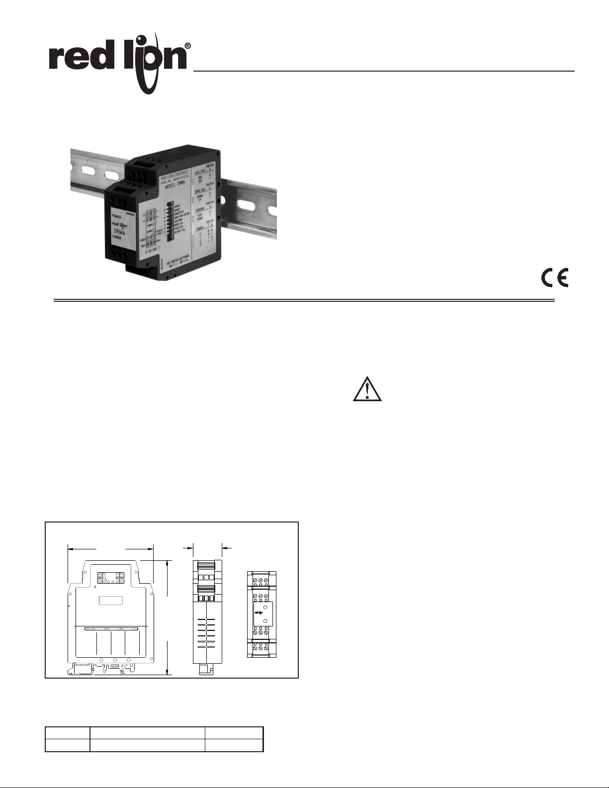
4.20 REF
1.08
3.12
(27.5)
(106.7)
(79.2)
ERROR
POWER
IRMA
DIP SWITCH SETTINGS:
ON = 1 OFF = 0
MC2234X
9-32 VDC
ERROR
POWER
VDC+ 10
RTD(S)
7
V+ 4
I+ 1
VDC-
RTD(-)
1211
98
65V-
32I-
78RANGE
RTD
OHMS
RTD TYPE
385
392
OPEN SEN
DOWN
SENSOR
UP
0
1
SWITCH
4
0
SWITCH
5
SWITCH
1
6
SWITCH
1
0
012
3
0
0
1
010
11
392/385
5 OPEN SEN UP/DN
OHMS/RTD
RANGE
1
4
3
2
OUTPUT CAL
FIELD CAL
BASIC CAL
876
RTD(+)
RANGE
MADE IN U.S.A.
RED LION CONTROLS
MODEL IRMA
YORK, PA.
USER PROGRAMMABLE INPUT
(RTD alpha = 0.00385 (DIN 43760), alpha = 0.00392, or resistance)
MICROPROCESSOR CONTROLLED
SIMPLE ADJUSTABLE RANGE SETTING (Using Input Signal)
RTD BREAK DETECTION
MOUNTS ON “T” AND “G” STYLE DIN RAILS
3-WAY ELECTRICAL ISOLATION (POWER/INPUT/OUTPUT)
MULTIPLE ANALOG OUTPUTS (0 to 20 mA, 4 to 20 mA, and 0 to
10 VDC)
WIDE OPERATING TEMPERATURE RANGE (-25°C to 75°C)
LED INDICATION (POWER & MEMORY ERROR)
9 to 32 VDC POWERED
DESCRIPTION
The IRMA accepts an RTD or resistance input and converts it into a voltage
or current output. The output is linearly proportional to the temperature or
resistance input. This output is ideal for interfacing to indicators, chart
recorders, controllers, or other instrumentation equipment.
The IRMA is DC powered. The DC power input is isolated from the signal
input and analog output. The unit scales the analog output proportionally to the
RTD or resistance input signal. The analog output may be configured for one of
the following: 0 to 20 mA, 4 to 20 mA, or 0 to 10 VDC. Making the signal
conversion with the IRMA to a current output signal, makes the signal less
susceptible to noise interference and allows accurate transmission over long
distances. The 3-Way isolation allows the use of grounded RTD’s which can
provide additional noise reduction benefits.
The IRMA uses an eight position DIP switch to accomplish the input sensor
configuration, range selection, and unit calibration. A simple range setting
technique (Field Calibration) is used so the actual input signal adjusts the output
for scaling. This technique eliminates the need for potentiometers which are
vulnerable to changes due to vibration.
The unit is equipped with a universal mounting foot for attachment to
standard DIN style mounting rails, including top hat rail (T) according to EN 50
7.5 and 35 15, and (G) profile according to EN 50 035 - G 32.
022 - 35
DIMENSIONS In inches (mm)
ORDERING INFORMATION
MODEL NO. DESCRIPTION PART NUMBER
IRMA Intelligent RTD Module IRMA3035
SAFETY SUMMARY
All safety related regulations, local codes and instructions that appear in the
manual or on equipment must be observed to ensure personal safety and to
prevent damage to either the instrument or equipment connected to it. If
equipment is used in a manner not specified by the manufacturer, the protection
provided by the equipment may be impaired.
CAUTION: Read complete instructions prior
to installation and operation of the unit.
SPECIFICATIONS
1. POWER: 9 to 32 VDC; 1.75 W. 200 mA max. current. The power supply
must have 400 mA for 200 msec. surge capacity.
2. INPUT: RTD 2, 3, or 4 wire, 100 ohm platinum, alpha = 0.00385
(DIN 43760), alpha = 0.00392, or resistance [selectable via DIP switches].
Excitation: 0.170 mA nominal
Lead resistance: Less than 0.5°C with 15 ohms max. per lead
Note: There is no lead compensation for 2 wire input. Field calibration
should be performed with equivalent series resistance.
3. OUTPUT: All output signals scaled linearly using temperature or resistance
input. Unit is shipped set for the 4 to 20 mA output. 4 to 20 mA or 0 to 20
mA selected via internal jumper.
Voltage Output Compliance:
0 to 10 VDC across min. 1 K load (10 mA)
20 mV peak to peak max. ripple (for frequencies up to 120 Hz)
Current Output Compliance:
0 to 20 mA through max. 600 load (12 VDC)
4 to 20 mA through max. 600 load (12 VDC)
15 mV peak to peak max. ripple across 600 load (for frequencies up to
120 Hz)
4. RTD BREAK DETECTION: Nominal values shown in the following order:
(0 to 20 mA, 4 to 20 mA, and 0 to 10 VDC).
Upscale: 22.9 mA, 22.5 mA, and 11.5 VDC
Downscale: -0.5 mA, 3.5 mA, and -0.4 VDC
5. RESPONSE TIME: 400 msec. (to within 99% of final value w/step input;
typically, response is limited to response time of probe.)
6. TEMPERATURE EFFECTS:
Temperature Coefficient: 0.025% of input range per C
7. DIELECTRIC WITHSTAND VOLTAGE: 1500 VAC for 1 minute
Working Voltage: 50 VAC
Power input to Signal input, Power input to Signal output, & Signal input to
Signal output.
1
Page 2

ANALOG
OUTPUT
CIRCUITRY
1
3
CIRCUITRY
CONTROL
PWM
POWER
SUPPLY
22V
3V
CIRCUITRY
PROCESS
CONVERTER
A/D
CURRENT
OUTPUT
12
10
4V
POWER
DC
6
4
+
+
-
-
VOLTAGE
OUTPUT
3V
9
8
7
0.170mA
8. RANGE & ACCURACY: (12 Bit resolution)
Accuracy: ( 0.075% Range + 0.1°C [Conformity]) at 23°C after 45 min.
warm-up, conforming to ITS-90.
Note: RTD Conformity does not apply to resistance input. For best accuracy,
calibration should be performed under operating conditions.
Relative Humidity: Less than 85% RH (non-condensing)
Span: The input span can be set to a min. of 1/8 of the full scale range,
anywhere within that range.
Range Accuracy
DIP SWITCH
INPUT RANGE
RTD alpha = 0.00385
RTD alpha = 0.00392
OHMS
Note: DIP switch settings ON = 1 OFF = 0
Accuracy Example:
RTD 385 Range “0”
-160°C to 654°C
TYPE RANGE
4 6 7 8
0 0 0 0 0 -160 to 654°C 0.61°C
1 0 0 0 1 -108 to 207°C 0.24°C
2 0 0 1 0 -5 to 414°C 0.31°C
3 0 0 1 1 194 to 608°C 0.31°C
0 1 0 0 0 -157 to 640°C 0.60°C
1 1 0 0 1 -106 to 203°C 0.23°C
2 1 0 1 0 -5 to 406°C 0.31°C
3 1 0 1 1 190 to 596°C 0.30°C
0 0 1 0 0 35.5 to 331.0 0.222
1 0 1 0 1 57.0 to 178.5 0.091
2 0 1 1 0 98.0 to 252.0 0.116
3 0 1 1 1 173.5 to 316.5 0.107
( ±0.61°C + ±0.1°C) = ±0.71°C
TEMPERATURE
& OHMS RANGE
ConformityRange
RANGE
ACCURACY
Total Error
9. CERTIFICATIONS AND COMPLIANCES:
SAFETY
IEC 61010-1, EN 61010-1: Safety requirements for electrical equipment
for measurement, control, and laboratory use, Part 1.
ELECTROMAGNETIC COMPATIBILITY
Immunity to EN 50082-2
Electrostatic discharge
EN 61000-4-2
Level 2; 4 kV contact
Level 3; 8 kV air
EN 61000-4-3Electromagnetic RF fields
Level 3; 10 V/m
80 MHz - 1 GHz
Fast transients (burst)
EN 61000-4-4
Level 4; 2 kV I/O
Level 3; 2 kV power
RF conducted interference
EN 61000-4-6
Level 3; 10 V/rms
150 KHz 80 MHz
Power frequency magnetic fields
EN 61000-4-8
Level 4; 30 A/m
Emission to EN 50081-2
RF interference
EN 55011
Enclosure class B
Notes:
1. This device was designed for installation in an enclosure. To avoid
electrostatic discharge, precautions should be taken when the device is
mounted outside an enclosure. When working in an enclosure (ex. making
adjustments, setting switches etc.) typical anti-static precautions should be
observed before touching the unit.
2. Self-recoverable loss of performance during EMI disturbance at 10 V/m:
Analog output signal may deviate during EMI disturbance.
For operation without loss of performance:
Unit is mounted in a metal enclosure (Buckeye SM7013-0 or equivalent)
I/O and power cables are routed in metal conduit connected to earth gr ound.
Refer to the EMC Installation Guidelines section of this bulletin for additional
information.
10. ENVIRONMENTAL CONDITIONS:
Operating Temperature Range: -25°C to 75°C (-13°F to 167°F)
Storage Temperature Range: -40 to 85°C (-40°F to 185°F)
Operating and Storage Humidity: 85% max. relative humidity (non-
condensing) from -25°C to 75°C.
Vibration According to IEC 68-2-6: Operational 5 to 150 Hz, in X, Y, Z
direction for 1.5 hours, 2 g’s.
Shock According to IEC 68-2-27: Operational 30 g’s, 11 msec in 3 directions.
Altitude: Up to 2000 meters
11. MOUNTING: Universal mounting foot for attachment to standard DIN
style mounting rails, including top hat (T) profile rail according to EN50022
7.5 and 35 15, and G profile rail according to EN50035 - G32.
- 35
12. CONNECTION: Compression type terminal block
13. CONSTRUCTION: High impact black plastic case, Installation Category I,
Pollution Degree 2.
14. WEIGHT: 4.02 oz. (114.0 g)
BLOCK DIAGRAM
FUNCTION DESCRIPTIONS
Open Sensor Detection
The output can be set to go Upscale or Downscale for the detection of an open
sensor. The nominal values for each output range are listed under RTD Break
Detection in the Specifications section. This setting is always active, so changes
to the setting are effective immediately.
Unit Malfunction
If the unit has scaling problems (output remains at -0.5 mA, 3.5 mA, or -0.5
VDC nominal), check the ERROR LED on the front of the unit. An E2PROM
problem is indicated when the ERROR LED is on. If the ERROR LED is on,
perform a Basic Calibration followed by a Field Calibration. Turn the power off
for 5 seconds. Turn power on and check if the ERROR LED is on. If the LED is
on, contact the factory.
EMC INSTALLATION GUIDELINES
Although this unit is designed with a high degree of immunity to
ElectroMagnetic Interference (EMI), proper installation and wiring methods
must be followed to ensure compatibility in each application. The type of the
electrical noise, source or coupling method into the unit may be different for
various installations. Cable length, routing and shield termination are very
1
important and can mean the difference between a successful or a troublesome
2
installation. Listed below are some EMC guidelines for successful installation in
an industrial environment.
1. Use shielded (screened) cables for all Signal and Control inputs. The shield
(screen) pigtail connection should be made as short as possible. The
connection point for the shield depends somewhat upon the application.
Listed below are the recommended methods of connecting the shield, in order
of their effectiveness.
a. Connect the shield only at the rail where the unit is mounted to earth ground
(protective earth).
b. Connect the shield to earth ground at both ends of the cable, usually when
the noise source frequency is above 1 MHz.
c. Connect the shield to common of the unit and leave the other end of the
shield unconnected and insulated from earth ground.
2. Never run Signal or Control cables in the same conduit or raceway with AC
power lines, conductors feeding motors, solenoids, SCR controls, and heaters,
etc. The cables should be run in metal conduit that is properly grounded. This
is especially useful in applications where cable runs are long and portable
two-way radios are used in close proximity or if the installation is near a
commercial radio transmitter.
3. Signal or Control cables within an enclosure should be routed as far away as
possible from contactors, control relays, transformers, and other noisy
components.
4. In extremely high EMI environments, the use of external EMI suppression
devices, such as ferrite suppression cores, is effective. Install them on Signal
and Control cables as close to the unit as possible. Loop the cable through the
core several times or use multiple cores on each cable for additional protection.
Install line filters on the power input cable to the unit to suppress power line
interference. Install them near the power entry point of the enclosure. The
following EMI suppression devices (or equivalent) are recommended:
Ferrite Suppression Cores for signal and control cables:
Fair-Rite # 0443167251 (RLC #FCOR0000)
TDK # ZCAT3035-1330A
Steward #28B2029-0A0
Line Filters for input power cables:
Schaffner # FN610-1/07 (RLC #LFIL0000)
Schaffner # FN670-1.8/07
Corcom #1VR3
Note: Reference manufacturer’s instructions when installing a line filter.
5. Long cable runs are more susceptible to EMI pickup than short cable runs.
Therefore, keep cable runs as short as possible.
2
Page 3
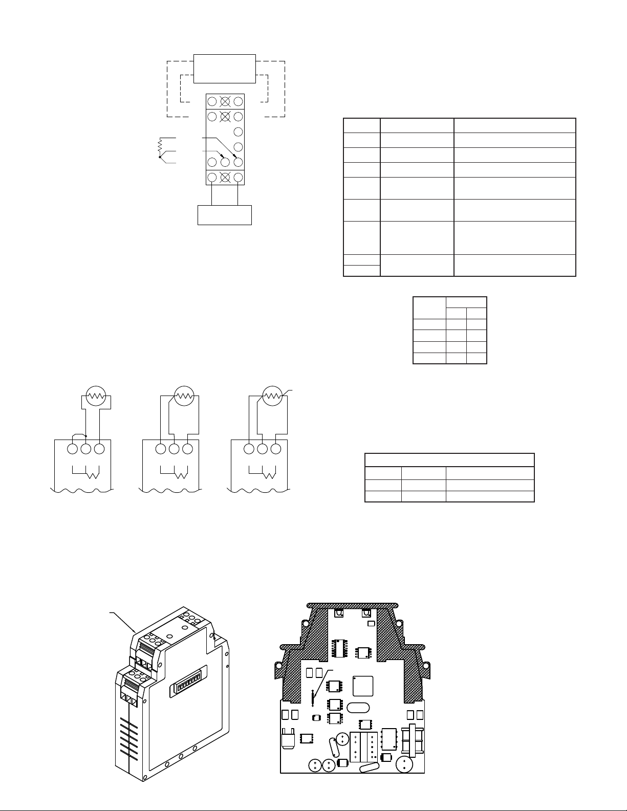
WIRING CONNECTIONS
ERROR
POWER
VDC+
10
RTD(S)
7
V+
4
I+
1
VDC-
RTD(+)
1211
98
65
V-
32
I-
POWER SUPPLY
9 to 32 VDC
VOLTAGE METER
OR
CURRENT METER
MONITORING INSTRUMENT
RTD(-)
87 9
RTD
S
-
+
-
RTD
+
7S8 9
RTD
7S8+9
-
3-WIRE RTD 4-WIRE RTD
N.C.
2-WIRE RTD
All conductors should meet
voltage and current ratings for
each terminal. Also, cabling
should conform to appropriate
standards of good installation,
local codes and regulations. It
is recommended that power
supplied to the unit be
protected by a fuse or circuit
breaker. When wiring the unit,
use the numbers on the label
to identify the position
number with the proper
function. Strip the wire,
leaving approximately 1/4" (6
mm) of bare wire exposed
(stranded wire should be
tinned with solder). Insert the
wire into the terminal, and
tighten the screw until the
wire is clamped tightly.
POWER
Connect DC power to terminals #10 and #12 observing proper polarity. Be
certain DC power is within the 9 to 32 VDC specifications.
POWER LED
The IRMA has a green LED located on the front to indicate that power is
applied to the unit.
DIP SWITCH SETTING DESCRIPTIONS
SWITCH
1 OUTPUT CAL Output Calibration
2 FIELD CAL Field Calibration
3 BASIC CAL Basic Calibration
4 385/392 RTD Type
5 OPEN SEN UP/DN
6 RTD/OHMS
LABEL
DESCRIPTION
Open Sensor Detection Upscale (ON) / Downscale (OFF)
Select Input Type Ohms (ON) / RTD (OFF)
INPUT AND POWER/OUTPUT CONNECTIONS
INPUT
When connecting the RTD or resistance device, be certain that the
connections are clean and tight. Attach the device to terminals #8 and #9. Install
a copper sense lead of the same gauge as those used to connect the device.
Attach one end of the wire at the probe where the lead connected to terminal #8
is attached and the other end to terminal #7. This configuration will provide
complete lead wire compensation. If a sense wire is not utilized, then Terminal
#7 should be shorted to terminal #8. T o avoid errors due to lead wire resistance,
field calibration should be performed with a series resistance equal to the total
lead resistance in the system. Always refer to the probe manufacturer’s
recommendations for mounting, temperature range, shielding, etc.
OUTPUT
Connect the output signal wires to the desired output terminals. For voltage
output, use terminals #4 and #6; for current output, use terminals #1 and #3
observing proper polarity. Only one output may be used at a time. The unit is
factory set for a 4 to 20 mA output. The voltage output will track the current
output linearly within ±2.5% deviation of range endpoints.
To select 0 to 20 mA, output you must open the case and cut the wire jumper.
The jumper is located to the left side of the board as shown in the drawing.
Remove this
side of the
unit case.
7
8
RANGE
Sensor Range - 2 switch
combination setting
Range switch settings (ON = 1 OFF = 0)
DIP SWITCH
RANGE
7 8
0 0 0
1 0 1
2 1 0
3 1 1
FACTORY SETTINGS
The unit is shipped from the factory calibrated for a 4 to 20 mA output using
a type 385 RTD in range 0. The IRMA should be Field calibrated by the
operator for the application environment it will be used in. If the unit is not
recalibrated by the operator, the following table lists the temperature ranges for
each RTD type.
NOMINAL FACTORY FIELD CALIBRATION
TYPE
385
392 0 150°C to 595°C
RANGE
0
TEMPERATURE RANGE
150°C to 606°C
TROUBLESHOOTING
For further technical assistance, contact technical support at the appropriate
company numbers listed.
WIRE JUMPER
3
Page 4

DIP SWITCH SETTINGS:
ON = 1 OFF = 0
9-32 VDC
V+
I+
VDC+
RTD(S)
POWER
RTD(-)
RTD(+)
VDC-
9
ERROR
78
1210 11
634152V-
I-
5
1
4
3
2
8
76RANGE
RANGE
OHMS/RTD
FIELD CAL
BASIC CAL
OUTPUT CAL
392
SEN UP/DN
MODEL IRMA
ERROR
POWER
VDC+
10
RTD(S)
7
V+
4
I+
1
VDC-
RTD(+)
1211
98
65
V-
32
I-
POWER SUPPLY
9 to 32 VDC
VOLTAGE METER
OR
CURRENT METER
MONITORING INSTRUMENT
RTD(-)
ADJUSTABLE
RESISTANCE
SOURCE
-
+
S
1.0 Field Calibration
CALIBRATION PROCEDURES
Field Calibration scales the selected output to a temperature or resistance
input. This procedure assigns an input value to the low end and an input value
to the high end. The microprocessor handles configuring the output so it is
linear to the temperature or resistance input. The Field Calibration procedure is
described below.
Note: The unit needs to have the Field Calibration completed by the operator
before normal operation. To abort this calibration and reset to the previous
settings, set the FIELD CAL switch OFF prior to the final OFF setting of the
OUTPUT CAL switch (Step 1.1 1) and turn off power. Wait 5 seconds and then
turn on power and the previous settings will be loaded.
1 6543287
ON
Step 1.2
1 6543287
Field Calibration Wiring
Step 1.3
1 6543287
Step 1.5
ON
ON
RTD temperature to resistance conversion table
Temperature
°C
alpha
0.00385
alpha
0.00392
34.3835.53-160
38.6439.71 -150
59.5560.25-100
79.9680.30-50
100.00100.000
119.75119.4050
139.20138.5100
158.36157.33150
173.48172.17190
177.23175.85200
195.80194.09250
Temperature
°C
alpha
0.00385
alpha
0.00392
214.08212.03300
232.07229.69350
249.77247.05400
253.28250.49410
267.18264.13450
284.30280.92500
301.13297.42550
314.38310.41590
317.66313.63600
330.68326.38640
333.90329.54650
Field Calibration with an Accurate Adjustable Resistance Source
Note: The nominal output value for the various output ranges are designated in the
following order: (0 to 20 mA, 4 to 20 mA, 0 to 10 VDC)
1.1 Connect resistance source to the RTD input terminals using a third sense wire.
(For 2 wire sensors, short terminal #7 to terminal #8.)
1.2 Set the type and Range for the RTD or resistance used in your application. (DIP
switches #4, #6, #7 & #8). (RTD alpha = 0.00385, Range 0 shown). APPLY
OPERATING VOLTAGE and allow 45 minute warm-up period.
1.3 Set the FIELD CAL switch (#2) ON. [Output goes to -0.8 mA, 3.5 mA, or -0.4 V
nominal]
1.4 Set the input resistance to the value intended to generate the analog low endpoint
(For 2 wire sensors, add the system lead resistance to the desired value.)
1.5 Set the OUTPUT CAL switch (#1) ON. [Output stays at -0.8 mA, 3.5 mA, or -0.4
V nominal]
1 6543287
Step 1.7
1 6543287
Step 1.9
1 6543287
Step 1.11
1 6543287
Step 1.12
1.6 Adjust the input signal up until the analog output equals desired low value.[0 mA,
4 mA, or 0 V]
ON
1.7 Set the OUTPUT CAL switch (#1) OFF. [Output increases to 22.9 mA, 22.5 mA,
or 11.5 V nominal]
1.8 Set the input resistance to the value intended to generate the analog high endpoint.
(For 2 wire sensors, add the system lead resistance to the desired value.)
ON
1.9 Set the OUTPUT CAL switch (#1) ON. [Output decreases to 21.1 mA, 20.7 mA,
or 10.6 V nominal]
1.10 Adjust the input signal down until the output equals desired high value. [20 mA,
20 mA, or 10 V]
ON
1.11 Set the OUTPUT CAL switch (#1) OFF.
1.12 Set the FIELD CAL switch (#2) OFF.
ON
1.13 Disconnect the resistance source from the IRMA and connect the actual sensor to
be used in the application.
4
Page 5

ERROR
POWER
VDC+
10
RTD(S)
7
V+
4
I+
1
VDC-
RTD(+)
1211
98
65
V-
32
I-
POWER SUPPLY
9 to 32 VDC
VOLTAGE METER
OR
CURRENT METER
MONITORING INSTRUMENT
RTD(-)
ADJUSTABLE
RESISTANCE
SOURCE
-
+
S
2.0 Basic Calibration
DIP SWITCH SETTINGS:
ON = 1 OFF = 0
9-32 VDC
V+
I+
VDC+
RTD(S)
POWER
RTD(-)
RTD(+)
VDC-
9
ERROR
78
1210 11
634152V-
I-
5
1
4
3
2
8
76RANGE
RANGE
OHMS/RTD
FIELD CAL
BASIC CAL
OUTPUT CAL
392
SEN UP/DN
MODEL IRMA
The Basic Calibration should only be performed with an ambient temperature between
21°C and 29°C. The Basic Calibration was performed on the unit at the factory and
generally does not need to be done again. This procedure initializes the unit by calibrating
the input. The Basic Calibration should be performed only if a condition exists as
described in the “Unit Malfunction” section. After completion of this calibration, the unit
needs to be scaled in Field Calibration. The Basic Calibration procedure is described
below.
Note: To abort this calibration and reset to the previous settings, set the BASIC CAL
switch(#3) OFF prior to the final setting of the OUTPUT CAL switch (#1) (Step 4.17)
and turn off power for 5 seconds. Then turn on power and the previous settings will be
loaded.
Note: The nominal output value for the various output ranges are designated in the
following order: (0 to 20 mA, 4 to 20 mA, 0 to 10 VDC)
Basic Calibration Wiring
12345678
Step 2.1
1 2345678
12345678
Steps 2.3 to 2.15
312 54 678
Step 2.16
2.1 Connect an adjustable resistance source with an accuracy of 0.03% to the RTD input
ON
terminals using a third sense wire. Set the RANGE (#7& #8), TYPE (#4), OUTPUT
CAL (#1), and FIELD CAL (#2) switches OFF. Set the BASIC CAL switch (#3) ON.
2.2 Apply operating power and allow a 45 minute warm-up period. [Current goes to -0.9
mA, 3.4 mA, or -0.5 V(nominal)]
2.3 Set the OUTPUT CAL switch (#1) ON and then OFF.
2.4 Set the resistance source to 40 ohms and wait 5 seconds.
2.5 Set the OUTPUT CAL switch (#1) ON and then OFF.
2.6 Set the resistance source to 60 ohms and wait 5 seconds.
2.7 Set the OUTPUT CAL switch (#1) ON and then OFF.
ON
2.8 Set the resistance source to 100 ohms wait 5 seconds.
2.9 Set the OUTPUT CAL switch (#1) ON and then OFF.
2.10 Set the resistance source to 175 ohms and wait 5 seconds.
ON
2.11 Set the OUTPUT CAL switch (#1) ON and then OFF.
2.12 Set the resistance source to 250 ohms and wait 5 seconds.
2.13 Set the OUTPUT CAL switch (#1) ON and then OFF.
2.14 Set the resistance source to 315 ohms and wait 5 seconds.
2.15 Set the OUTPUT CAL switch (#1) ON and then OFF.
2.16 Set the BASIC CAL switch (#3) OFF. [Current increases to 3.6 mA (nominal) or
more]
ON
2.17 Perform a Field Calibration. (See Section 1.0)
5
Page 6

ERROR
POWER
VDC+
10
7
V+
4
I+
1
VDC-
1211
98
65
V-
32
I-
MELT FLOW
MONITORED
MACHINE'S
POWER SUPPLY
24VDC
COMM
MASTER
CONTROL
ROOM
+
-
RTD(+)
RTD(S)
RTD(-)
INSTALLATION
The unit is equipped with a universal mounting foot for attachment to standard DIN style mounting rails,
including G profile rail according to EN50035 - G32 , and top hat (T) profile rail according to EN50022 - 35 x 7.5
and 35 x 15. The unit should be installed in a location that does not exceed the maximum operating temperature and
provides good air circulation. Placing the unit near devices that generate excessive heat should be avoided.
To install the
IRMA on a “G”
style DIN rail, angle
the module so that
the upper groove of
the “foot” catches
under the lip of the
top rail. Push the
module toward the
rail until it snaps
into place. To
remove a module
from the rail, push
up on the bottom of
the module while
pulling out away
from the rail.
G Rail Installation
To install the IRMA
T Rail Installation
on a “T” style rail,
angle the module so
that the top groove of
the “foot” is located
over the lip of the top
rail. Push the module
toward the rail until it
snaps into place. To
remove a module from
the rail, insert a
screwdriver into the
slot on the bottom of
the “foot”, and pry
upwards on the module
until it releases from
the rail.
APPLICATION
injection molding process. Different plastic grades and the complexity of the
mold determine required temperatures for efficient material flow. The master
control room monitors the temperature of the melt flow of each injection mold
machine. They will determine whether the operator may start the process on his
machine or override the injection molding process. The injection molding
machines are located throughout the plant, posing an RTD signal loss problem
from long cable runs. The IRMA DC powered unit is mounted at the machine
and uses the local 24 VDC for power. The signal loss problem is solved using
the 4 to 20 mA analog output for the long cable run to the master control room.
The temperature of certain industrial plastics is critical for melt flow of an
6
 Loading...