

red lion IndustrialPro SN-6621, IndustrialPro SN-6601 Quick Start Manual
QUICK START GUIDE
IndustrialPro
CDMA SN-6621 or SN-6601
TM
Cellular Router
UNPACKING INSTRUCTIONS
1. Unpack the Red Lion unit and verify the following components are
enclosed for the IndustrialPro Router: SN-6621 or SN-6601 and
this Quick Start Guide.
Antennas and power supply sold separately
CDMA MODELS SN-6621 OR SN-6601
SN-6621-S (SPRINT); SN-6621-V (VERIZON); SN-6621-US (US
CELLULAR) - units are carrier specific
1. The unit will need to be activated with a cellular carrier. If not, con-
tact your cellular carrier and provide them with the ESN number
located on the bottom label of the unit.
2. An antenna with an SMA connector should be connected to the
router. This antenna should meet the following specifications:
• Dual-band 800 & 1900 MHz
• Nominal 50 ohm impedance
• Voltage Standing Wave Ration (VSWR) less than 2.5.1
3. There are 3 methods to provide power to the router:
A. 4-pin Molex connector - available on SN6x00
ACCESSING THE WEB USER INTERFACE
1. Connect PC to IndustrialPro Router
Connect a CAT-5 Ethernet cable between the local PC and the unit’s
Ethernet port. Verify that the link LED is lit
2. Setup PC IP Address.
For assistance with configuring your PC, see the appropriate Microsoft support webpage listed at:
http://support.microsoft.com
PC to Ethernet Interfaces
Select “Use the following IP address” and fill in the blank fields
with the information below
IP Address 192.168.0.2
Subnet Mask 255.255.255.0
Default Gateway 192.168.0.1
Preferred DNS 192.168.0.1
3. Access Web User Interface
Open a web browser and enter the following in the address bar:
http://192.168.0.1:10000
:
Ethernet 0
LOGIN INSTRUCTIONS
• User Name: admin (lowercase letters)
• Password: last six digits of the unit’s serial number
B. 4-pin screw terminal - available on Sn-6xx1/EB
C. Side mounted 2.5mm barrel connector - all models
D. Power-over-Ethernet - available on SN-6x01EB
The modem required a power source between 8 and 30 VDC to
operate:
LABEL COLOR DESCRIPTION
GND Black Ground
PWR+ Red Power 8 to 30 VDC
IN White Digital and analog input
OUT Green Digital output
5. Please allow 2-4 minutes for the unit to recognize the cellular data
card and connect to the cellular network. When this has occurred,
the signal strength LEDs should light up (see table on back). If signal strength is not lit or flashes slowly, please refer to the User
Manual at www. redlion.net.
6. Connect to the Ethernet RJ45 port for network connectivity.
CONNECT. MONITOR. CONTROL. © 2014 Red Lion Controls. All Rights Reserved 1
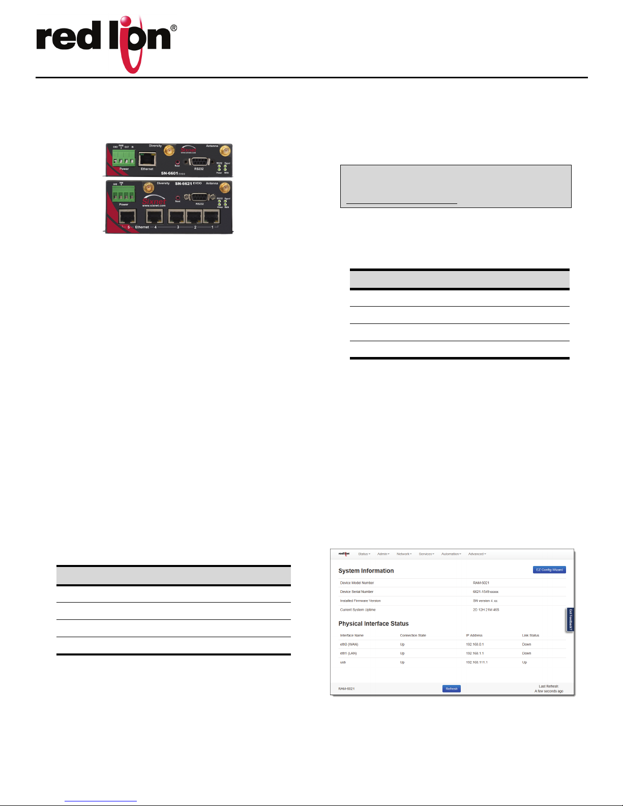
Upon successfully logging in, the web UI will launch.
Note: For security purposes, it is recommended that the admin password be changed according to your internal policies.
To change password, go to: Admin->Access Settings.
Web UI:
You are now connected to the web interface. If you should see anything
other than the screen shown above, please refer to the RAM-6021 User
Manual, located on our website: www.redlion.net.

Quick Start Guide
VERIFY CELLULAR CONNECTIVITY
Confirm the following on the web UI after logged into the unit:
Activation: “Succeeded” or “Unavailable”
Connection: “Enabled”
IP Address: Populated with a network IP address
Signal strength has GREEN bars populated. If you see any RED bars represented under signal Strength, please consult the User Manual. WAN
(Eth0) should show up and show the network issued IP address.
If you were unable to confirm this status on the Summary page, please
refer to the User Manual for troubleshooting steps on our website:
www.redlion.net.
If you are able to confirm this status, then your unit is successfully connected to the cellular network via WAN (Eth0).
HARDWARE STATUS LEDs
LED State Description
Power ON Power is applied to the router
ON Excellent signal strength
Signal
WAN
FLASH Flashes faster as signal is stronger
OFF
ON
FLASH
Very weak or no signal
(less than -100dBM)
Wireless link established, but no data
activity
Data transmitted/received on wireless
network
INSTALLATION AND HAZARDOUS AREA WARNINGS
All power, input and output I/O wiring must be in accordance with Class
I, Division 2 wiring methods are in accordance with the authority having
jurisdiction. This equipment is suitable for Use in Class 1, Division 2,
Groups A, B, C and D or Non-Hazardous Locations Only.
WARNING - EXPLOSION HAZARD - SUBSTITUTION OF COMPONENTS
MAY IMPAIR SUITABILITY FOR CLASS I, DIVISION 2.
WARNING - EXPLOSION HAZARD - WHEN IN HAZARDOUS LOCATIONS,
DISCONNECT POWER BEFORE REPLACING OR WIRING UNITS.
WARNING - EXPLOSION HAZARD - DO NOT DISCONNECT EQUIPMENT
UNLESS POWER HAS BEEN SWITCHED OFF OR THE AREA IS KNOWN TO
BE NON-HAZARDOUS.
AVERTISSEMENTS POUR INSTALLATION ET
ENDROITS DANGEREUX
Tout pouvoir, le câblage d'entrée et de sortie (I/O) doivent être conformes aux méthodes de câblage de Classe I, Division 2 et conformément à l'autorité compétente. Cet équipement est adapté pour une
utilisation en Classe1, Division 2, Groupes A, B, C et D ou endroits nondangereux seulement
AVERTISSEMENT - RISQUE D'EXPLOSION - LA SUBSTITUTION DE TOUT
COMPOSANT PEUT NUIRE À LA CONFORMITÉ DE CLASSE I, DIVISION 2.
AVERTISSEMENT - RISQUE D'EXPLOSION - LORSQUE DANS DES
ENDROITS DANGEREUX, DÉBRANCHEZ LE CORDON D'ALIMENTATION
AVANT DE REMPLACER OU DE BRANCHER LES MODULES.
AVERTISSEMENT - RISQUE D'AVERTISSEMENT - NE DÉBRANCHEZ PAS
L'ÉQUIPEMENT PENDANT QUE LE CIRCUIT EST DIRECT OU À MOINS
QUE L'ENVIRONNEMENT SOIT CONNU POUR ÊTRE LIBRE DE CONCENTRATIONS INFLAMMABLES
ON
RS232
FLASH
ON Link established with Ethernet device
Ethernet
FLASH
Link established with serial device but no
data activity
Data transmitted/received with attached
serial device
Data transmitted/received with attached
Ethernet device
RED LION CONTROLS TECHNICAL SUPPORT
If you have followed all of the instructions up to this point, are satisfied
that you are not having an authentication problem, are convinced that
you have sufficient reception, and your unit is still not communicating,
then it is time to contact Red Lion Technical Support
at support@redlion.net or 1-877-432-9908.
FCC COMPLIANCE STATEMENT
This equipment has been tested and found to comply with the limits for
a Class A digital device, pursuant to part 15 of the FCC rules. These limits are designed to provide reasonable protection against harmful interference when the equipment is operated in a commercial environment.
This equipment generates uses and can radiate radio frequency energy;
and if not installed and used in accordance with the instructions, may
cause harmful interference to radio communications. Operation of this
equipment in a residential area is likely to cause harmful interference to
radio communications, in which case the user will be required to correct the interference at their own expense. Warning: Changes or modifications to this unit not expressly approved by the party responsible for
compliance could void the user's authority to operate the equipment.
Information to the user:
If this equipment causes interference to radio or television reception,
which can be determined by turning the equipment off and on, the user
is encouraged to try to correct the interference by one or more of the
following measures: In order to meet FCC emissions limits, this equipment must be used only with cables that comply with IEEE 802.3. If necessary, the user should consult the dealer or an experienced radio/
television technician for additional suggestions. The user may find the
following booklet prepared by the Federal Communications Commission helpful: “How to Identify and Resolve Radio-TV Interference Problems”. This booklet is available from: U.S. Government Printing Office,
Washington, DC 20402, Stock No. 004-000-00345-4
CONNECT. MONITOR. CONTROL. © 2014 Red Lion Controls. All Rights Reserved 2
 Loading...