

THE APOLLO INTELLIGENT METER SERIES
MODEL IMH INSTRUCTION MANUAL
INTRODUCTION
The Intelligent Meter for 5 Amp AC input (IMH) is another unit in our multipurpose series of industrial control products that are field-programmable to solve
multiple applications. This series of products is built around the concept that the
end user has the capability to program different personalities and functions into
the unit in order to adapt to different indication and control requirements.
The Intelligent Meter which you have purchased has the same high quality
workmanship and advanced technological capabilities that have made Red Lion
Controls the leader in today’s industrial market.
Red Lion Controls has a complete line of industrial indication and control
equipment, and we look forward to being of service to you now and in the future.
CAUTION: Risk of Danger.
Read complete instructions prior to
installation and operation of the unit.
CAUTION: Risk of electric shock.

TABLE OF CONTENTS
GENERAL DESCRIPTION 2-3
A) Safety Summary
B) Block Diagram
C) Theory of Operation
PROGRAMMING AND OPERATING THE IMH
A) Programming the IMH
B) Program Modules #1 thru #9
C) Operating the IMH (Quick Programming)
D) Factory Configuration
E) Programming Example
F) Motor Monitoring Example
TOTALIZER/LINEARIZER/PEAK/VALLEY/TARE (Optional)
A) Totalizer Example
B) Linear Segmenting Example
ALARMS (Optional)
RE-TRANSMITTED ANALOG OUTPUT (Optional)
APPENDIX “A” - INSTALLATION AND CONNECTIONS
A) EMC Installation Guidelines
B) Select AC Power (115/230 VAC)
APPENDIX “B” - SPECIFICATIONS AND DIMENSIONS
APPENDIX “C” - TROUBLESHOOTING GUIDE
APPENDIX “D” - PROGRAMMABLE FUNCTIONS
APPENDIX “E” - ORDERING INFORMATION
2
3
4
4-21
4-5
6-17
18
19
20
21
22-24
22-23
23-24
25
26-27
28-30
29
29
31-32
33
34-35
36
-1-

GENERAL DESCRIPTION
The Apollo Intelligent 5 Amp AC Current Meter (IMH) accepts AC currents
up to 5 amps and precisely scales them into engineering units with high
resolution. With the use of an external 5 amp AC current transformer, of any
ratio, currents of any magnitude can be measured and displayed. The meter is
calibrated from the factory to display RMS value of a pure sinusoidal signal. The
input is AC coupledtoeliminate any DCeffectsin the signal. True RMSreadings
are not obtained from complex waveforms, such as square waves, signals that
have been rectified or chopped due to a circuit with an SCR or Triac outputs.
These kind of complex waveforms will cause average value readings.
Examples of such waveforms are shown below:
Example A is an undistorted sinewave and the IMH will indicate true RMS.
With the complex waveforms shown in Examples B and C, the meter will
indicate average value.
Internal resolution of 1 mA allows detection and indication of the smallest
signal change. A two Hz, two pole, low-pass filter coupled with programmable
digital filtering can be tuned to match the characteristics of any process. A digital
tare (re-zero) operation can beperformed at a touch of a button along with recall
of process peak and valley (max/min). State-of-the-art digital circuitry virtually
eliminates errors due to drift. A full complement of option packages is available
to fulfill many process applications.
The indicator features a choice of two different scaling procedures which
greatly simplifies initial set-up. A full 6-digit display accommodates virtually
any process engineering unit. English-style display prompts and front panel
buttons aid the operator through set-up and operation. A front panel lock-out
menu protects set-up data and operation modes from unauthorized personnel.
Programmable remote input “E1-CON” can be utilized to control a variety of
totalizing, alarm control, display hold and tare operations. All set-up data is
stored in E
power.
2
PROM, which will hold data for a minimum of 10 years without
An optionalintegrator (totalizer)/linearizer can be used to totalize or integrate
signals up toa maximum display value of999999. It features independent scaling
and a low signal cut-out to suit a variety of signal integration applications.
Programmable remote input “E2-CON” pin is included with this option and can
be utilized to control a variety of functions, such as totalizing, alarm control,
peak/valley readings, display hold or tare operations, simultaneously with
“E1-CON” pin. Additionally, nine slopes and offsets can easily be programmed
to linearize processes with non-linear outputs, such as square law devices.
Peak/valley (max/min) reading memory, and a signal re-zeroing (tare) function
are included and they are easily recalled and controlled by the front panel. All
readings are retained at power-down.
Optional dual relays with parallel solid state outputs are fully programmable
to operate ina wide varietyof modes tosuit many controlor alarm applications.
An optional 4 to 20 mA or 0 to 10 VDC re-transmitted analog output can be
scaled by the user to interface with a host of recorders, indicators and controllers.
The type of analog output is determined by the model ordered. (See Ordering
Information for available models.) The indicator has several built-in diagnostic
functions to alert operators of most any malfunction. Extensive testing of noise
interference mechanisms and full burn-in makes the indicator extremelyreliable
in industrial environments. The die-cast front bezel meets NEMA 4/IP65
requirements for washdown applications, when properly installed. Plug-in style
terminal blocks simplify installation and wiring change-outs.
SAFETY SUMMARY
All safety related regulations, local codes and instructions that appear in the
manual or on equipment must be observed to ensure personal safety and to
prevent damage to either the instrument or equipment connected to it. If
equipment is used in a manner not specified by the manufacturer, the protection
provided by the equipment may be impaired.
Do not use this unit to directly command motors,valves, orother actuators not
equipped with safeguards. To do so, can be potentially harmful to persons or
equipment in the event of a fault to the unit.
-2-
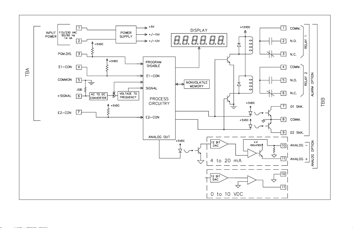
FIG. 1: BLOCK DIAGRAM
Note: Analog (-) and Alarm common are separate and isolated from the signal common.
The commons should NOT be tied together. Check label for wiring connections.
-3-
THEORY OF OPERATION
The IMH employs a microprocessor to perform the A/D conversion on the
input signal via a voltage-to-frequency converter. It digitally scales the result,
corrects for meter drift which may be present and then displays the result in a
6-digit display(5 for input, 6 for totalizer). Theinputs are filtered to enhance the
stability of the display. A non-volatile E
2
PROM memory device provides
permanent data retention for operating variables. The display consists of drivers
and 6-digit solid-state LEDs. The alarm option employs opto-isolators to isolate
the open collector devices from meter common. Operating in parallel, the relays
are type Form-C and are rated at 5 Amps. The analog option features a 12-bit
DAC and provides an output signal that is digitally scaled. The re-transmitted
output is isolated from meter common.
PROGRAMMING THE IMH
Prior to installing and operating the indicator, it may be necessary to change
the scaling to suit thedisplay units particular tothe application. Although the unit
has been pre-programmed at the factory, the set-ups will generally have to be
changed.
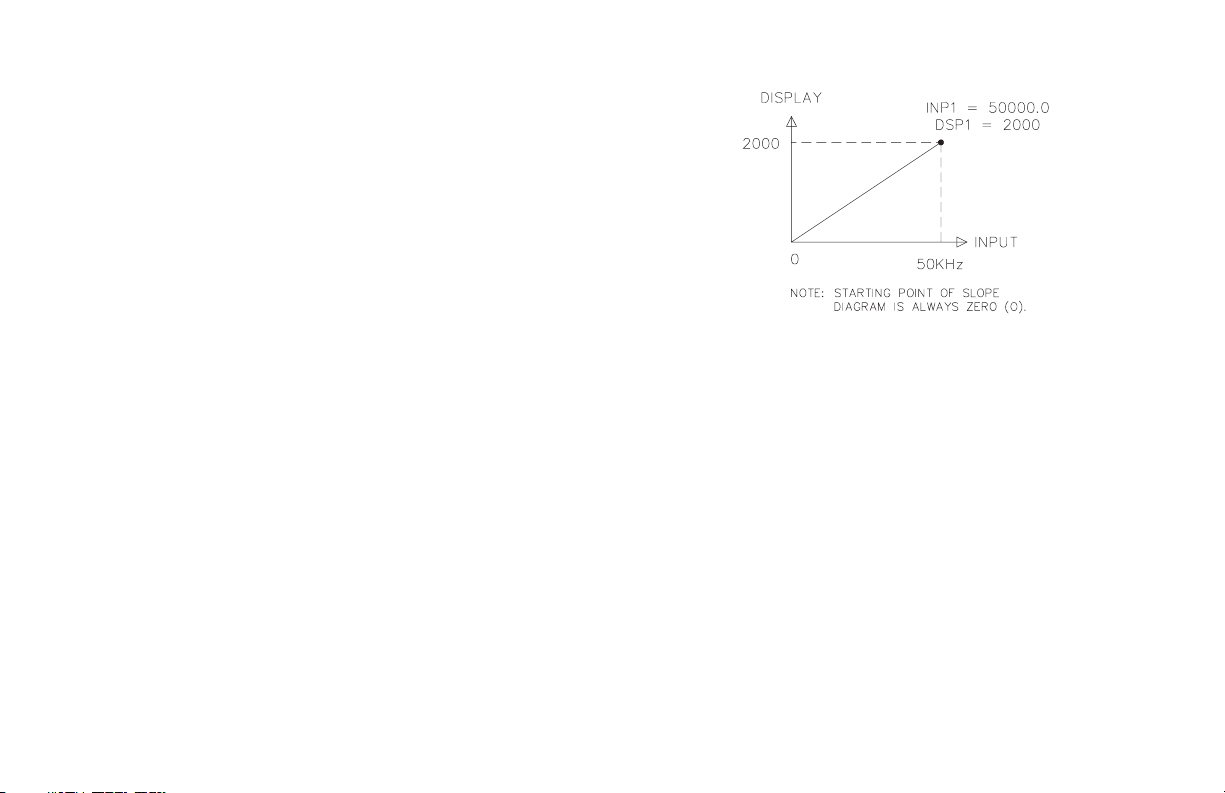
The indicator isunique in that two different scalingmethods areavailable. The
operator may choose the method that yields the easier and more accurate
calibration. The two scaling procedures are similar in that the operator keys-in
two display values and eitherkeys-in or applies a signal valuethat corresponds to
those display points (see FIG. 2). The location of the scaling points should be
near the process end limits, for the best possible accuracy. Once these values are
programmed (coordinates on a graph), the indicator calculates the slope and
intercept of the signal/display graph automatically. No span/zero interaction
occurs, making scaling a one-pass exercise. Basic scaling is complete after
decimal point selection, unit rounding (dummy zeros) and digital filtering level
selection. The following procedure should be followed to scale the indicator.
FIGURE 2: SLOPE DIAGRAM
Before actuallytrying toprogram the indicator, it is advised to organize all the
data for the programming steps to avoid any possible confusion and to read the
programming procedure entirely before proceeding.
To set-up the indicator, connect AC power and signal wires as outlined in the
connections section(Appendix “A”). Remove the jumperwire (ifinstalled) from
TBA #3 (PGM. DIS.). This will allow the operator to enter and modify all of the
indicator’s parameters. Press the front panel button labeled “P”, momentarily.
Briefly, the display will show “Pro” alternately flashing with “0”.Thisisthe
indicator’s programming mode. The programming mode isdivided intosections,
numbered 0-9, each of which can be individually accessed. The front panel
“UP” and “DOWN” arrow buttons can be used to select one of these numbers
and the “P” button used to enter the selected programming module. In all of the
programming modules, “UP” and “DOWN” are used to either select from a list
of choices or enter a value. The “P” button is used to save the new value and
progress to the next step within a module (Note: the new value takes effect when
“P” is pressed). Upon completionof a module, the indicatorreturns to the “Pro”
<>“0”. Pressing the “P” button at this point causes the unit to display “End”,
after which the unit returns to normal mode. The following table explains the
basic function of each step.
Note: < > This indicates that the display will alternate between the English
prompt and the actual data.
-4-

DISPLAY RESULT OF “P” BUTTON
DISPLAY
RESULT OF “P” BUTTON
“Pro”< >“0” - Causes the indicator to return to normal display mode. Any
changes to set-up data arepermanently storedin the E
2
PROM.
“Pro”< >“1” - Entry into this module allows the user to select the decimal point
position, unit rounding and scaling by the method of applying
the actual signal levels to the indicator that corresponds to the
programmed display values. Use this method when the
indicator is connected to the process and the process can be
brought to known levels. Alternately, a precision AC current
source may be substituted to simulate the process. A second
method is available in Pro 2.
“Pro”< >“2” - Entry into this module allows the user to select the decimal point
position and unitrounding, as in Pro 1,but themethod of scaling
differs in that the user keys in signal levels instead of applying
signals to the indicator. Use this method when the process
(signal source) is calibrated with known display values at
known signal levels.An alternate method isavailable in Pro1.
“Pro”< >“3” -Module #3allows the user toprogram what canbe accessedfrom
the front panel when the PGM. DIS. (Program Disable, TBA
#3) pin is connected to common. This feature protects critical
set-up data from accidental modification while allowing access
to setpoints and other functions. The front panel lock-out menu
(quick programming) includes setpoint modification, totalizer
resetting, zeroing the input and peak/valley resetting.
Note: The term “Quick Programming” is used to refer to the
ability to change the information that can be accessed from the
front panel when the “PGM. DIS.” terminal is connected to
“COMM.”.
“Pro”< >“4” - Module #4 programs the digital filtering level and the function of
the remote input “E1-CON” pin (TBA #4) and if the totalizer
option is installed the remoteinput “E2-CON”pin (TBA #7).The
functions of the remote E1 and E2 pins are the same and include
display hold, peak/valley modes, totalizer reset, alarm reset,
signal re-zero (tare) reading synchronization or print request.
“Pro”< >“5” - This module sets the decimal point position, time base, scale
factor and low signal disable function for the
totalizer/integrator.
“Pro”< >“6” - Thismodule allows programmingfor thebasic configurationof the
alarm option. The programming includes HI/LO acting, tracking,
alarm display, latched or auto-reset, assignment to either signal or
integrator/totalizer and alarm and hysteresis values.
“Pro”< >“7” - Not used
“Pro”< >“8” - This module allows digital scaling of the re-transmitted analog
output. Display values that correspond to 4 mA or 0 VDC and
20 mA or 10 VDC arekeyed-in to scale the output and it may be
assigned to either the signal or the integrator/ totalizer.
“Pro”< >“9”- This module is the service operations sequence and is not normally
accessed by the user. This step re-calibrates the basic input and is
used to compensate for long-term drift. Execution of this module
should be done by technicians with the proper equipment in
accordance with a maintenance plan of yearly re-calibrations. A
code number entry step is used to protect frominadvertent entries.
Also, there is a number of other access codes, which provide test
and set-up changes as an aid in troubleshooting.
-5-

PROGRAMMING MODULE #1 - SCALE BY SIGNAL LEVEL METHOD
PROGRAM DECIMAL POINT POSITION
Select the desired decimal point position of the scaled display by pressing
either the “Up” or “Down” button.
Note: Whatever decimal point is selected will appear in succeeding
programming steps. Also, the “P” button must be pressed after each step to
enter the desired data and to proceed to the next step.
“dECPNt”<>“0”
“0.0”
“0.00”
“0.000”
“0.0000”
PROGRAM ROUNDING INCREMENT AND RIGHT HAND
DUMMY ZEROS
Rounding values other than one cause the scaled number to ‘round’ to the
nearest rounding increment selected (ie. rounding of ‘5’ causes ‘122’ to round to
‘120’ and ‘123’to round to ‘125’). If the process is inherentlyjittery, the display
value may be rounded to a value higher than one. If the range of the process
exceeds therequired resolution,(ex. 0-3.000 AMPS AC , but only 0.010 AMP AC
resolution required), a rounding increment of 10 will effectively make the
display more stable. This programming step is usually used in conjunction with
programmable digital filtering (Pro 4) to help stabilize display readings. (If
display stability appearsto be a problemand thesacrifice indisplay resolution is
unacceptable, program higher levels of digital filtering or increase the level of
process dampening.) Rounding increments of 10, 20, 50, and 100 may also be
used to add “dummy zeros” to the scaled readings, as desired.
“round ”< > “1”
“2”
“5”
“10”
“20”
“50”
“100”
At this stage,a choice of eitherto returnto “Pro0” orto continuewith scaling
of the display is offered.
“SCALE” < > “yES”
“NO”
If “YES” was selected for theprevious step, the scaling procedureis started. In
order to scale the indicator, two signal level values and two display values that
correspond to the signal values must be known. These four values are used to
complete the scaling operation. An example of a signal-display pair is listed
below:
0.00 % @ 0.000 Amps AC AND 100.00 % @ 5.000 Amps AC
Scaling point #1 Scaling point #2
KEY-IN DISPLAY VALUE FOR SCALING POINT #1
“dSP 1” < > “-99999” to “99999” (ex. 0.00 %)
APPLY SIGNAL TO INDICATOR FOR SCALING POINT #1
The meter will indicate the actual amount of signal being applied to theinput.
However, the indicator still retains the previously applied value until “P” is
pressed, at which time the new value is stored. Pressing either the “UP” or
“DOWN” button causes the previous value to remain programmed in the unit.
“INP 1” < > “0.000 to 5.000 Amps AC” (ex. 0.000)
KEY-IN DISPLAY VALUE FOR SCALING POINT #2
“dSP 2” < > “-99999” to “99999” (ex. 100.00 %)
APPLY SIGNAL TO INDICATOR FOR SCALING POINT #2
The meter will indicate the actual amount of signal being applied to theinput.
However, the indicator still retains the previous value until “P” is pressed, at
which time the new valueis stored.Pressing either the “UP” or “DOWN”button
causes the previous value to remain programmed in the unit.
“INP 2”< > “0.000 to 5.000 Amps AC” (ex. 5.000)
-6-

The indicatorwill be ready to accept more scaling points (if more aredesired)
for multisegment linearization. The quantity and location of the linearization
points should be chosen very carefully to best utilize the segments available.
Refer to the section on linearization for a discussion on this matter.
At this stage, scaling is complete. The indicator will automatically calculate
the slope and offset of the display units. After completing Pro 1, it is
recommended that the scaling operation be verified by applying various signals
and checking the displayed reading.
PROGRAM NUMBER OF LINEAR SEGMENTS
This programming step loads in the number of linear segments desired for
multisegment linearization. If single slope scaling is desired, input “1” for this
step. If two segments aredesired, input “2”, etc.You must haveone more scaling
point known than the number of segments selected (ie. 1 segment = 2 points, 2
segments = 3 points, etc). This step may be used to deactivate previously
programmed segments where lower segments would override higher segments.
(ex. changing “SEGt” from 5 to 3 causes slopes 4 & 5 to be replaced by an
extension of slope 3).
“SEGt”< >“1” - “9”
If “1” was selected, the indicator will return to “Pro 0” since scaling for the
first segment was already completed. Otherwise, a choice of either returning to
“Pro 0” or commencing with the multislope linearization scaling is offered.
“SCALE” < > “yES”
“NO”
KEY-IN DISPLAY VALUE FOR POINT #3
If “YES” was selected, the display value for the third point is entered.
Otherwise, the indicator returns to “Pro 0”.
“dSP 3” < > “-99999” to “99999”
APPLY SIGNAL TO INDICATOR FOR POINT #3
The signal level value for point 3 is applied.
“INP 3” < > “0.000 to 5.000 Amps AC”
The sequence of entering display and signal values continues with “dSP 4”,
“INP 4”, “dSP 5”, etc. until the number programmed for “SEGt” is reached.
Upon completion, the indicator is scaled to the multiple segments. It is
recommended that the scaling be checked by exiting the programming mode and
applying signal values and verifying for correct display values.
* Note As the “UP” or “DOWN” button is continually held in, the display will
progressively increment faster until the fourth most significant digit is
changing at a rate of 1 number per second.
-7-

PROGRAMMING MODULE #2 - SCALE BY KEY-IN METHOD
PROGRAM DECIMAL POINT POSITION
Select the desired decimal point position of the scaled display by pressing
either the “Up” or “Down” button.
Note: Whatever decimal point is selected will appear in succeeding
programming steps. Also, the “P” button must be pressed after each step to
enter the desired data and to proceed to the next step.
“dECPNt”<>“0”
“0.0”
“0.00”
“0.000”
“0.0000”
PROGRAM ROUNDING INCREMENT AND RIGHT HAND
DUMMY ZEROS
Rounding values other than one cause the scaled number to ‘round’ to the
nearest rounding increment selected (ie. rounding of ‘5’ causes ‘122’ to round to
‘120’ and ‘123’to round to ‘125’). If the process is inherentlyjittery, the display
value may be rounded to a higher value than one. If the range of the process
exceeds the required resolution, (ex. 0-3.000 AMPS AC, but only 0.010 AMP AC
resolution required), a rounding increment of 10 will effectively make the
display more stable. This programming step is usually used in conjunction with
programmable digital filtering (Pro 4) to help stabilize display readings. (If
display stability appearsto be a problemand thesacrifice indisplay resolution is
unacceptable, program higher levels of digital filtering or increase the level of
process dampening.) Rounding increments of 10, 20, 50, and 100 may also be
used to add “dummy zeros” to the scaled readings, as desired.
“round” < > “1”
“2”
“5”
“10”
“20”
“50”
“100”
At this stage,a choice of toeither returnto “Pro0” orto continuewith scaling
of the display is offered.
“SCALE” < > “yES”
“NO”
If “YES” was selected for theprevious step, the scaling procedureis started. In
order to scale the indicator, two signal level values and two display values that
correspond to the signal values must be known. These four values are directly
entered into the indicator. An example of a signal-display pair is listed below:
0.00 % @ 0.000 Amps AC AND 100.00% @ 5.000 Amps AC
Scaling point #1 Scaling point #2
KEY-IN DISPLAY VALUE FOR SCALING POINT #1
“dSP 1”< >“-99999” to “99999” (ex. 0.00 %)
KEY-IN SIGNAL VALUE FOR SCALING POINT #1
“INP 1” < > “0.000 to 5.000 AMPS AC” (ex. 0.000)
KEY-IN DISPLAY VALUE FOR SCALING POINT #2
“dSP 2” < > “-99999” to “99999” (ex. 100.00%)
KEY-IN SIGNAL VALUE FOR SCALING POINT #2
“INP 2” < > “0.000 to 5.000 AMPS AC” (ex. 5.000)
The indicatorwill be ready to accept more scaling points (ifmore are desired)
for multisegment linearization. The quantity and location of the linearization
points should be chosen very carefully to best utilize the segments available.
Refer to the section on linearization for a discussion on this matter.
At this point, scaling is complete. The indicator will automatically calculate
the slope and offset of the display units. After completing Pro 2, it is
recommended that the scaling operation be verified by applying various signals
and checking the displayed reading.
-8-

PROGRAM NUMBER OF LINEAR SEGMENTS
This programming step loads in the number of linear segments desired for
multisegment linearization. If single slope scaling is desired, program “1” for
this step. If two segments are desired,program “2”, etc. You must haveone more
scaling point known than the number of segments selected (ie. 1 segment = 2
points, 2 segments = 3 points, etc). This step may also be used to deactivate
previously programmed segments where lower segments would override higher
segments. (ex. changing “SEGt” from 5 to 3 causes slopes 4 & 5 to be replaced
by an extension of slope 3).
“SEGt”<>“1-9”
If “1” was selected, the indicator will return to “Pro 0” since scaling for the
first slope was already completed. Otherwise,a choiceof either returning to“Pro
0” or commencing with the multislope-linearization scaling is offered.
If “yes” was selected, the display value for the third point is entered.
Otherwise, the indicator returns to “Pro 0”.
“SCALE” < > “yES”
“NO”
KEY-IN DISPLAY VALUE FOR SCALING POINT #3
“dSP 3”< >“-99999” to “99999”
KEY-IN INPUT VALUE FOR SCALING POINT #3
“INP 3”< >“0.000 to 5.000 AMPS AC”
The sequence of entering display and signal values continues with “dSP 4”,
“INP 4”, “dSP 5”, etc.until thenumber programmed for “SEGt” is reached. Itis
recommended that the scaling be checked by exiting the programming mode and
applying signal values and verifying for correct display values.
Note: As the “UP” or “DOWN” button is continually held in, the display will
progressively increment faster until the fourth most significant digit is
changing at a rate of one number per second.
-9-

PROGRAMMING MODULE #3 - PROGRAM FUNCTIONS ACCESSIBLE WITH FRONT PANEL LOCKOUT
This programming module programs what is accessible through the front
panel when the PGM.DIS. pin is connected to common (COMM. TBA #5).
Note: The term“Quick Programming” is used to referto the ability tochange the
information that can be accessed from the front panel when the “PGM.DIS.”
terminal is connected to “COMM.”.
DISPLAY ALARM VALUES
If the alarm option is installed, this selects whether the alarm values will or
will not be displayed.
“dSP AL” < > “yES” or “NO”
ENTER ALARM VALUES *
If “YES” was selected for display alarmvalues, this will select if alarm values
may be modified from the front panel. (If “NO” was selected for display alarm
values, then this step will default to “NO” and will not be displayed for
selection.)
“ENt AL” < > “yES” or “NO”
DISPLAY HYSTERESIS VALUES
If the alarm option is installed, this selects whether the hysteresis values will
or will not be displayed.
“dSPHYS” < > “yES” or “NO”
ENTER HYSTERESIS VALUES *
If “YES” was selected for display hysteresis values, this selects whether
hysteresis values may be modified from the front panel. (If “NO” was selected
for display hysteresis values, then this step will default to “NO” and will not be
displayed for selection.)
“ENtHYS” < > “yES” or “NO”
RESET LATCHED ALARMS
If thealarm option isinstalled, thiswill select if a latched alarm(s) can be reset
from the front panel.
“rSt AL” < > “yES” or “NO”
DISPLAY PEAK/VALLEY MEMORY BUFFER
If the totalizer/linearizer option is installed, this selects whether peak and
valley buffers will be displayed.
“dSPbUF” < > “yES” or “NO”
RESET PEAK/VALLEY MEMORY BUFFER *
If “YES” was selected for the previous step, this selects whether the peak and
valley buffersmay bereset fromthe front panel. (If “NO” was selected, then this
step defaults to “NO” and will not be displayed for selection.)
“rStbUF” < > “yES” or “NO”
SELECT DISPLAY **
If the totalizer/linearizer option is installed, this selects whether the display
can be switched from input display to total display and from totaldisplay to input
display.
Note: When “NO” is selected, the display mode that was being displayed before
entering programming, will be the only display accessible.
“SELdSP” < > “yES” or “NO”
* This sequence may be subject to being locked out due to other
programmed sequences.
** This function operates independent of the state of the “PGM.DIS.” pin.
-10-

RESET TOTAL **
If the totalizer/linearizer option is installed, this selects whether the total can
be reset from the front panel.
“rSttOt” < > “yES” or “NO”
RE-ZERO INPUT **
If thetotalizer/linearizer option is installed, this selects whether the signal can
be re-zeroed (tared) or not.
“tArE” < > “yES” or “NO”
Note: The tare buffer can be cleared by “walking” through “Pro 2", using the P
button.
Depending on functions selected under Pro 3 and Pro 6, alarms, hysteresis,
peak, and valleyvalues canbe monitoredand/or changed when PGM. DIS.is tied
to COMM. This provides a “QUICK PROGRAMMING” method for “day to
day” process changes. (See QUICK PROGRAMMING SECTION for more
details.)
* This sequence may be subject to being locked out due to other programmed
sequences.
** This function operates independent of the state of the “PGM.DIS.” pin.
-11-

PROGRAMMING MODULE #4 - PROGRAM DIGITAL FILTER AND REMOTE INPUT
PROGRAM DIGITAL FILTERING
If the displayed process signal is difficult to read due to small process
variations or noise, increased levels of filtering will help to stabilize the display.
This programming step may be used in conjunction with display rounding
programming(Pro1&2)to help minimizethis effect. The digital filter used is an
“adaptive” filter. That is, the filter coefficients change dynamically according to
the nature of the input signal. This feature simultaneously allows the filter to
settle quickly for large inputchanges whileproviding a stable display reading for
normal process variations. Because of the adaptive nature of the filter, it cannot
be characterized in terms of a time constant. The following table lists the
maximum settling time for a step input to within 99% of final value.
“FILtEr” < > “0” - no digital filtering 1.5 sec.
Filter Value Settling Time (99%)
“1” - normal filtering 2 sec.
“2” - increased filtering 6 sec.
“3” - maximum filtering 13 sec.
PROGRAM FUNCTION OF E1-CON AND OPTIONAL
E2-CON PIN
The function of the remote input “E1-CON” pin (TBA #4) and, if the totalizer
option is installed, the remote input “E2-CON” pin (TBA #7) are the same.
Functions are activated, as described in the appropriate function, when
connected to signal common (TBA #5). Whether a function is edge or level
activated it must be held low for a minimum of 20 msec in order for the function
to occur. The remote input pins can be used simultaneously and with any
combination of functions. When pins are tied together and activated, E1-CON
function is generally performed first.
“E1-CON” < > “0” - A negative going edge re-zeros (tares) the input signal.
Note: The tare buffer can be cleared by “stepping” through
“Pro 2”, using the P button.
“1” - A negative going edge resets the contents of the totalizer to
zero. Totalization commences regardless of the state of the
input.
“2” - A negative going edge resets the contents of the totalizer to
zero and allows totalization as long as the input is low. If the
input goes high, totalization is stopped and the contents are
saved. Thisacts as a totalization enable control from time T1 to
T2.
“3” - A low level allows totalization from the previously saved
contents as long as the input is low. If the input goes high,
totalization isstopped and the contents are saved. This actsas a
totalization enable control from time T1 to T2.
“4” - Alow level holds the display(display hold).While this inputis
low, the indicator continues to process the input signal and
drive the alarms, totalizer, etc. with the actual signal. The
contents of the totalizer are stored at the same time when the
input display is held.
Note: If display hold is activated, and input value was showing
in the display, the operator can switch to total value by pressing
the up button.
“5” - A negative going edge resets both peak and valley buffers.
Note: After P/V is called up, a change will not appear on the
display until the next time the P/V is called up.
“6” - A negative going edge resets only the peak buffer and the
indicator enters a peak reading display mode as long as the
input is low. If the input goes high, peak detection and
indication is stopped and the last peak reading is retained.
“7” - A negative going edge resets only the valley buffer and the
indicator enters a valley reading display mode as long as the
input is low. If the input goes high, valley detection and
indication are stopped and the last valley reading is retained.
“8” - If the alarmoption is installed, a negative going edgeresets the
latched alarm(s).
“9” - If the alarm option is installed, a low level resets a latched or
unlatched alarm into its inactive state. This provides manual
override of alarms for systemstart-up andother unusual events
such as system testing.
“10” - A negative going edge toggles the display between “input”
and “total” (from input to total, or vice versa). No action is
taken on the positive going edge.
-12-

“11” - A negative going edge zeros(tares) theinput signal and adds
the value that was in the input display to the totalizer value
every time this operation is performed. The time-base, scale
factor and low cut-out in “Module #5” are in effectively
disabled, when this function is selected
“12” - Display hold with tare. A negative going edge tares (zeros)
the input signal. Prior to the tare operation, the input signal is
saved and held (display hold) as long as the remote input pin is
low. On the positive edge the input display will show zero. If
there is an increase to the inputsignal while the remote input is
“E2-CON” < > - If the E2-CON option is installed, E2-CON has the same
“13” - Instrument reading synchronization. A low level disables all
PROGRAMMING MODULE #5 - PROGRAM TOTALIZER / INTEGRATOR
low, the display will reflect (show) the increase at the positive
edge.
meter operations (alarms, total, analog out, etc.). A positive
edge resets the start of the A/D conversion, to allow
synchronization with external process and controls. While in
this function, the other E-CON pin is operational.
programmable functions as E1-CON.
Programming for the totalizer/integrator consists of four programming steps:
decimal point position, time base, scale factor and low signal disable. Note that
the decimal pointposition ofthe integrator/totalizer can be setindependent of the
decimal point position of the input. Thetotalizer willroll over and flash when the
total exceeds, 999999 or -99999, indicating an overflow condition.
PROGRAM DECIMAL POINT POSITION FOR THE
TOTALIZER
The decimal point positions for the totalizer are as follows:
“dECPNt”<>“0”
“0.0”
“0.00”
“0.000”
“0.0000”
PROGRAM TOTALIZER/INTEGRATOR TIME BASE
The time base determines the rate at which readings increase. The totalizer
display is updated 2 1/2 times per second regardless of time base selected, but
longer time bases decrease the magnitude of each increase. The three time bases
are per second, per minute and per hour.A constant signal input of1000 units, for
example, would totalize to 1000 units in one second (withaTBof1sec.), 1000
units in one minute (withaTBof1min.), and 1000 units in one hour (withaTBof
1hr.).
Note: Input changes can be made synchronous to the display by programming
E1 or optional E2-CON pin for function 13, Instrument reading
synchronization.
A multiplying scale factor may be used to span the standard time ranges (or
divide if scale factor < 1). The following equation expresses the totalization
process.
If Program Select Number Chosen Is:
-13-
D.T.
S.F. =
I.D. TIME I.D.D.P.
S.F. = Programmable Scale Factor
D.T. = Desired Totalizer Value for a
fixed time duration
T.B. = Programmable Time Base
“0” for sec. 1
“1” for min. 60
“2” for hr. 3600
I.D. = Input Display Value
TIME = Actual Time period in seconds
T.B.xD.T.D.P.
x
Enter in Formula

PROGRAMMING MODULE #5 - PROGRAM TOTALIZER / INTEGRATOR (Cont’d)
D.T.D.P. = Desired Totalizer Decimal Point
01
0.0 10
0.00 100
0.000 1000
0.0000 10000
I.D.D.P. = Input Display Decimal Point
01
0.0 10
0.00 100
0.000 1000
0.0000 10000
“tbASE” < > “0” - per second
“1” - per minute
“2” - per hour
Enter in Formula
Enter in Formula
PROGRAM THE TOTALIZER SCALE FACTOR
As explained in the previous programming step, a multiplying scalefactor can
be used to scale theupdate rate as required. This maybe used to span the standard
ranges. A scale factor of “1.000” has no effect on the standard ranges.
“SCLFAC” < > “0.001” to “100.000”
PROGRAM THE LOW-END CUTOUT (low signal level disable)
In order to prevent false totalization during system start-up or other low
process situations wheretotalization isundesirable, aprogrammable setpoint can
be used to disable totalization when the scaled input signal falls below this
low-end cutout level.
“Lo-cut” < > “-99999” to “999999”
PROGRAMMING MODULE #6 - PROGRAM ALARM / SETPOINT
If the alarm option is installed, this module is used to configure the operation
of thealarms to avariety ofcombinations. The programmable options are HI/LO
acting, auto/manual reset (latching), tracking, assignment to signal or totalizer,
display alarms, alarm values and hysteresis (deadband) values.
ALARM TRACKING
With alarm tracking, whenever alarm #2is changed,alarm #1 will also change
so thatthe offset between alarm #2 and alarm#1 remainsthe same. This is useful
for hierarchical setpoints (pre-alarm and alarm) when one change applies to
both alarm values.When programmingfrom thefront panel, trackingonly occurs
when PGM.DIS. is low (front panel lock-out mode, alarm #1 will not appear).
“trAc”<>“yES”or“NO”
DISPLAY ALARMS
If display alarms are desired, a message will flash on the display every 5-10
secs when an alarm activates. For Alarm 1 the message will flash “AL1 on” and
alarm 2 will flash “AL2 on”, this warns an operator of an alarm condition. The
message will stop when the unit is no longer in an alarm condition.
“dISP” < > “yES” or “NO
”
AUTO OR MANUAL RESET FOR ALARM #1
The reset action of alarm #1 may be programmed to reset automatically
(unlatched) or be programmed torequire amanual reset (latched), through either
a remote input (Pro 4, E1-CON or optional E2-CON) or through the front panel
(Pro 3, reset latched alarms). Latched alarms are usually used when an operator
is required to take some action for the alarm condition.
“LAtC-1” < > “yES” or “NO”
-14-

ALARM #1 ASSIGNMENT TO INPUT SIGNAL OR TOTALIZER
Alarm #1 may be programmed to activate on either the input signal or the
totalizer value. If the totalizer option is not installed, this step defaults to the
input.
“ASN-1”< >“INPUt” or “totAL”
ALARM #2 ASSIGNMENT TO INPUT SIGNAL OR TOTALIZER
Alarm #2 may be programmed to activate on either the input signal or the
totalizer value. If the totalizer option is not installed, this step defaults to the
input.
“ASN-2” < > “INPUt” or “totAL”
PROGRAM VALUE FOR ALARM #1
The range of the alarm value is -99,999 to 999,999.
“AL-1” < > “-99999” to “999999”
PROGRAM HYSTERESIS VALUE FOR ALARM #1 (Cannot be
programmed if alarm latch is programmed)
The hysteresis (deadband) value for alarm #1 may be programmed from 1 to
999,999. The value is either added to or subtracted from the alarm value
depending on whether the alarm is high or low acting. (See alarm section for
operation.)
“HYS-1”< >“1” to “999999”
ALARM #1 HIGH OR LOW ACTING
The action of alarm #1 may be programmed to activate either when the signal
goes above the alarm value (high acting) or goes below it (low acting).
“Act-1”<>“HI”or“LO”
AUTO OR MANUAL RESET FOR ALARM #2
The reset action of alarm #2 may be programmed to reset automatically
(unlatched) or be programmed torequire amanual reset (latched), through either
a remote input (Pro 4, E1-CON or optional E2-CON) or through the front panel.
Latched alarms are usually used when an operator is required to take corrective
action for the alarm condition.
“LATC-2” < > “yES” or “NO”
PROGRAM VALUE FOR ALARM #2
The range of the alarm value is -99,999 to 999,999.
“AL-2” < > “-99999” to “999999”
PROGRAM HYSTERESIS VALUE FOR ALARM #2 (Cannot be
programmed if alarm latch is programmed)
The hysteresis (deadband) value for alarm #2 may be programmed from 1 to
999,999. The value is either added to or subtracted from the alarm value
depending onwhether the alarm ishigh or low acting. (See “alarms” section for
operation.).
“HYS-2” < > “1” to “999999”
ALARM #2 HIGH OR LOW ACTING
The action of alarm #2 may be programmed to activate either when the signal
goes above the alarm value (high acting) or goes below it (low acting).
“Act-2”<>“HI”or“LO”
Note: Depending on options selected under Pro 3 and Pro 6,alarms, hysteresis,
peak, and valley values can be monitored and/or changed when PGM.DIS. is
tiedtoCOMM.Thisprovidesa“QUICKPROGRAMMING”methodfor“day
to day” process changes. (See QUICK PROGRAMMING SECTION for more
details.)
-15-

PROGRAMMING MODULE #7 - NOT USED
PROGRAMMING MODULE #8 - PROGRAM RE-TRANSMITTED ANALOG OUTPUT
This programming module allows digital scaling of the 4 to 20 mA or 0 to 10
VDC analog output. The type of analog output is determined by the model
ordered. (See Ordering Information for available models.) The display value at
which4mAor0VDCandthedisplayvalueatwhich20mAor10VDCare
transmitted are keyed-in. The indicator automatically calculates slope and
intercept values to complete the scaling. The analog output then follows the
calculated display value and as such will update every measurement cycle. The
output may also be programmed to re-transmit the contents of the totalizer
instead of the input. Reverse acting output can be achieved by programming the
“high” displayvalue for the “AN-LO” programming stepand the “low” display
value for the “AN-HI” step.
Note: DO NOT ADJUST THE ANALOG OUTPUT POTS ON THE BACK OF
THE UNIT. Fine offset and span adjustment pots are externally accessible to
compensate for small drifts in the output. These pots have been set at the
factory and do not normally require adjustment.
ANALOG OUTPUT SOURCE
Program whether the input signal or the totalizer willserve as the basis forthe
analog output signal. If the totalizer option is not installed, this step defaults to
the input.
“ASIN” < > “INPUt” or “totAL”
ANALOG OUTPUT LO DISPLAY VALUE
Program the display value at which the analog output transmits 4 mA or 0
VDC.
“AN-Lo” < > “-99999” to “999999”
ANALOG OUTPUT HI DISPLAY VALUE
Program the display value at which the analog output transmits 20 mA or 10
VDC.
“AN-HI” < > “-99999” to “999999”
Programming of the re-transmitted analog output signal is complete. The
indicator will return to “Pro 0”.
-16-

PROGRAMMING MODULE #9 - SERVICE OPERATIONS
CALIBRATING THE SIGNAL INPUT
The indicator has been fully calibrated at the factory and will only require a
scaling operation (Pro1or2)to display the units of the process. If the unit
appears to be indicating incorrectly or inaccurately, refer to the troubleshooting
section before attempting this procedure.
When re-calibration is required (generally every 2 years), this procedure
should onlybe performed by qualified technicians using appropriate equipment.
Signal source accuracies of 0.1% or better are required.
The procedure consists of applying accurate signal levels to the indicator in a
series of three steps. Allow a 30-minute warm-up period before starting this
procedure.
Note: Once the access Code (48) has been entered, there is no exiting this
program module without completing the calibration procedure.
ENTER ACCESS CODE
A code number (48) must be keyed-in prior to the calibration sequence to
guard againstinadvertent entries.Access codenumbers otherthan thoselisted in
this section, should not be entered at this step. If any are entered, undefined or
unpredictable operation could result.
“CodE” < > “0” to “99”
If the code number for the previous step was not recognized, the indicator
returns to “Pro 0”, with no action taken. Otherwise, the calibration procedure is
started.
ENTER ZERO REFERENCE
This can be accomplished by opening 5 AMP input of TBA #5. Allow the
signal to stabilize for 20 seconds before pressing “P”.
“StEP 1” (Press “P”)
ENTER 50% OF RANGE
Apply 2.500 AMPS AC to input terminals. Allow signal to stabilize for 20
seconds before pressing “P”.
“StEP 2” (Press “P”)
ENTER 100% OF RANGE
Apply 5.000AMPS AC to input terminals. Allow the signal to stabilizefor 20
seconds before pressing “P”.
“StEP 3” (Press “P”)
Indicator calibration is complete. It is recommended that calibration be
checked by entering “Pro 1” and checking the displayed input values with the
signal source at different applied input levels.
RESTORING ALL PROGRAMMING PARAMETERS BACK TO
FACTORY CONFIGURATION
All of the programming in Modules #1 thru #8 can be restored back to the
factory configuration by entering a specific access code (refer to the “Factory
Configuration” section for the data that will be entered). The procedure consists
of entering “Pro 9”, keying-in “Code 66”, and then pressing “P”.TheIMH
responds by displaying “INItAL” for several seconds, and then returns to “Pro
0”.
Note: When this procedure is performed, ALL of the scaling, presets, etc. that
were programmed into the IMH will be overwritten.
“CodE” < > “66”
-17-

OPERATING THE IMH
After completing scaling and all set-up operations, the unit is ready to install
and operate. After power is applied, a display test consisting of illuminating all
segments for 2 seconds is performed. Afterward, the input or total will appear,
depending upon the display mode prior to the last power-down. To switch the
display to input, press “DOWN” (indicated by “arrows” on the front panel) and
to switch to total, press “UP”. A minus sign “-” will precede numbers that are
negative. If a decimal point is chosen,one leading and one or more trailing zeros
will accompany the decimal point.
QUICK PROGRAMMING
To limit access to the set-up parameters, connect a key-switch or wire from
PGM.DIS. (TBA #3) to COMM. (TBA #5). With this pin connected to common,
only a predeterminedamount of data can be viewed oraltered, asprogrammed by
programming module #3. If “NO” was programmed for all of the available steps
in module #3, then pressing “P” will cause the unit to display “Loc”. However,
if “YES” was programmed in oneor more of thesteps, then “P” will invokeentry
into a series of commonly modified parameters while protecting the crucial
set-up information. This is referred to as the “quick” programming mode. When
“quick” programming mode is entered, the alarms and hysteresis values can be
modified in the same manner as in the regular programming mode. The new
alarm and hysteresis values will take effect when “P” is pressed. The other
operations in the “quick” programming mode require special key sequences as
shown:
To reset a latched alarm, scroll through steps in “quick”
programming mode using the “P” button until “LAtCH1” or
”LAtCH2” appears in the display. If they do not appear, they are
not latched.
To reset: While “LAtCH1” or ”LAtCH2” is being
displayed, press and hold “DOWN” and press “P”.
Pressing “P” alone causes no action on the alarm.
To reset peak and valley buffers, scroll through steps in “quick”
programming mode using the “P” button until “PEA” or “VAL”
appears in the display.
To reset: While “PEA” or“VAL” is being displayed,
press and hold “DOWN” and press “P”. Pressing
“P” alone causes no action on the buffer.
The front panel buttons are not only used to input data during the
programming and “quick” programming mode, but control a number of other
functions (if enabled in Pro “3”) as well. In the normal meter mode, these
functions are available:
To switch to display of input: Press “DOWN” button
To switch to display of totalizer: Press “UP” button
To re-zero input (tare): Press and hold “DOWN” and press “P”
To reset totalizer to zero: Press and hold “UP” and press “P”
To enter programming or “quick” programming: Press “P”
After each operation, a message will appear briefly to acknowledge
the action.
-18-

FACTORY CONFIGURATION
The following chart lists the programming of the unit when shipped from the
factory. All of the programmed parameters can be restored back to the Factory
Configuration by entering a specific access code in “Pro 9”. Refer to the
“Programming Module #9” section for the procedure.
“Pro 1 or 2”......“dECPNt” - 0.00
“round” - 0.01
“dSP 1” - 0.00
“INP 1” - 0.000
“dSP 2” - 100.00
“INP 2” - 5.000
“SEGt” - 1
“Pro 3”..........“dSP AL” - yES
“ENt AL” - yES
“dSPHYS” - yES
“ENtHYS” - yES
“rSt AL” - yES
“dSPbUF” - yES
“rStbUF” - yES
“SELdSP” - yES
“rSttOt” - yES
“tArE” - yES
“Pro 4”..........“FILtEr” - 1 (normal filtering)
“E1-CON” - 4 (display hold)
“E2-CON” - 4 (display hold)
“Pro 5”..........“dECPNt” - 0
“tbASE” - 0 (1 second)
“SCLFAC” - 1.000
“Lo-cut” - 0.00
“Pro 6”..........“trAc” - NO
“dISP” - NO
“LAtC-1” - NO
“ASN-1” - input
“AL-1” - 0.00
“HYS-1” - 0.01
“Act-1” - HI
“LAtC-2” - NO
“ASN-2” - input
“AL-2” - 0.00
“HYS-2” - 0.01
“Act-2” - HI
“Pro 8”..........“ASIN” - input
“AN-Lo” - 0.00
“AN-HI” - 100.00
-19-

PROGRAMMING EXAMPLE
As an example programming sequence, the IMH is employed to monitor AC
current in aspecific circuitof a plant. The proper current transformer ratio with a
5 amp AC output is selected.
DISPLAY: 0.00% at 0.000 amps AC and 100.00% at 5.000 amps AC.
Resolution of 0.05%. Normal filtering. Latch alarm #1 if the input exceeds
90.00%, alarm must be manually reset by remote input, activate display
alarms. Peak and valley (max/min) readings for each day to be recorded.
TOTALIZER: Integrate (average)the inputon a per-hour basis. When the total
exceeds 13,140 activate alarm #2. Disable totalization when input falls below
10.00%.
ANALOG RE-TRANSMISSION: Drive chart recorder. 4mA @ 0.00% and
20mA @ 100.00%.
“Pro 1”.....Not required since scaling done in “Pro 2”.
“Pro 2”.....“dECPNt” - Enter 0.00
“round” - Enter 0.05
“SCALE” - Enter yES
“dSP 1” - Enter 0.00
“INP 1” - Enter 0.000
“dSP 2” - Enter 100.00
“INP 2” - Enter 5.000
“SEGt” - Enter 1
“Pro 3”.....“dSP AL” - Enter yES
“ENt AL” - Enter yES
“dSPHYS” - Enter NO
“rSt AL” - Enter NO
“dSPbUF” - Enter yES
“rStbUF” - Enter yES
“SELdSP” - Enter yES
“rSttOt” - Enter yES
“tArE” - Enter NO
“Pro 4”.....“FILtEr” - Enter 1 (normal filtering)
“E1-CON” - Enter 8 (reset latched alarm)
“E2-CON” - Not applicable
“Pro 5”....“dECPNt” - Enter 0
“tbASE” - Enter 2
“SCLFAC” - Enter 0.010
“Lo-cut” - Enter 10.00
“Pro 6”.....“trAc” - Enter NO
“dISP” - Enter yES
“LAtC-1” - Enter yES
“ASN-1” - Enter input
“AL-1” - Enter 90.00
“HYS-1” - Not applicable
“Act-1” - Enter HI
“LAtC-2” - Enter NO
“ASN-2” - Enter total
“AL-2” - Enter 13140
“HYS-2” - Enter 1
“Act-2” - Enter HI
“Pro 8”.....“ASIN” - Enter input
“AN-Lo” - Enter 0.00
“AN-HI” - Enter 100.0
-20-

MOTOR MONITORING EXAMPLE
An IMH is employed to monitor AC current of a single-phase 10 horsepower
115V AC motor. Also, the meter will be used to total current for preventative
maintenance purposes. Knowing the maximum full load currentis 100amps AC,
a current transformer (CT) of 100:5 ratio is selected.
The IMH is scaledto indicate0.00 at an input of 0.000 amps AC and 100.00 at
5.000 amps AC. Alarm#1 isprogrammed to activate if the motor currentexceeds
84.00 amps AC, which is a 40% increase in current draw from the nominal of 60
amps AC. Alarm #1 is disabled by external control pin during motor start-up due
to current surges. Peak and valley (max/min) reading for each day are to be
recorded.
The amount of current drawn by an electric motor gives a good indication of
the overall condition of the motor. Using the totalizer to total current and
knowing the nominal current draw is 60 amps AC, preventative maintenancecan
be performed on total amp-hours. Assigned to the totalizer, Alarm #2 is
programmed to latch when the predetermined amount of total amp-hours is
reached (ex. 4320 amp-hours). Totalization is disabled if the input is below 30
amps AC.
-21-

TOTALIZER/LINEARIZER/PEAK/VALLEY/TARE
(optional)
TOTALIZER
The totalizer option simply totals (adds) input readings together using a
programmable time base and scaling coefficient. The decimal point position of
the totalizer can be programmed independently of the input signal. The totalizer
may be reset through a remote input or by the front panel. Alarms may be
programmed to trigger from totalizer values. The programmable time bases are
“per second”, “per minute” and “per hour”, meaning the totalizer will
accumulate at a fixed rate of 2 1/2 times per second and be equal to a fixed input
signal level over the selected time period. For example, if the input signal is a
constant 1000 units and the “per minute” time base is selected, the totalizer will
accumulate at the rate of 1000 units per minute. The totalizer is updated at this
rate every 400 msec. As a result, the input signal is accumulated in “batches” of
6.6 counts every 400 msec. Therefore, the totalizer start and stop sequencing, as
well as thealarm values setto triggerat specifictotalizer values,are accurateonly
to the 400 msec totalizer update rate. The preceding example requires a scale
factor of 1.000 to yield exact time bases, but any scale factor can be used to span
between the ranges. (See section on totalizer programming for detailed
information.) A programmable low signal level disable feature completes the
totalizer features (this will stop totalization when the signal level drops below
this programmed value, “low cut”). At loss of power to the indicator, the
contents of the totalizer are saved. This will allow totalizing over consecutive
shifts, days, etc. The total can accumulate to 999,999.
Note: The totalizer will roll over and flash when the total exceeds, 999999 or
-9999, indicating an overflow condition.
TOTALIZER EXAMPLE
An IMH is employed to indicate and totalize amp-hours of an electric heater
element. A current transformer with a 5 amp AC output and the proper ratio is
selected (ex. 50:5). The input is scaled to indicate 0.00 to 50.00 amps AC.
Knowing the heater element nominal current draw is 40 amps AC and the
element should be serviced every 8760 amp-hours, the following programming
steps are followed:
BASIC SCALING
“Pro 2”...“dECPNt” - 0.00
“round” - 0.01
“dSP 1” - 0.00
“INP 1” - 0.000
“dSP 2” - 50.00
“INP 2” - 5.000
TOTALIZER SET-UP
With an average signal input of 40 amps AC for the Process Display, the
following formula applies:
TB = If Program Select Number Chosen Is:
D.T.D.P. = Desired Totalizer Decimal Point
I.D.D.P. = Input Display Decimal Point
D.T.
S.F. =
I.D. TIME I.D.D.P.
S.F. = Programmable Scale Factor
D.T. = Desired Totalizer Value for a
T.B.=ProgrammableTimeBase
“0” for sec. 1
“1” for min. 60
“2” for hr. 3600
I.D. = Input Display Value
TIME = Actual Time period in seconds
01
0.0 10
0.00 100
0.000 1000
0.0000 10000
01
0.0 10
0.00 100
0.000 1000
0.0000 10000
T.B.)*xD.T.D.P.
(
x
fixed time duration
Enter in Formula
Enter in Formula
Enter in Formula
-22-

S.F. =
x (
3600 **)*
40
40.00 3600 100
1
x
S.F.=1x1x0.01
S.F. = 0.01
“Pro 5”...“dECPNt” - 0
“tbASE” - 2
“SCLFAC” - 0.010
“Lo-cut” - 0.00
The totalizer will totalize up to 999999 (999,999 Amp-Hours).
* This valueis normally 1,but canbe usedas acoarse scalefactor of 60 or 3600.
** Since the time period is in Hrs., the selected T.B. is 3600 (Program Select
Value = 2) which equals per hour (3600 sec.)
LINEARIZER
The linearizerfeature is a series of programmable scaling points thatare used to
construct linearsegments tolinearize the input signal. Correction for non-linearity
is accomplished by continuing with scaling points beyond “DSP 2” and “INP 2”
in “Pro 1” or “Pro 2”, with “DSP 3”,and“INP 3”, “DSP 4”,and“INP 4”,etc.
The unit automatically calculates the linear segments between the programmed
coordinates. This process of entering linear segments is also known as “curve
fitting”. A maximumof ninesegments areavailable. No restriction is placed on the
ordering of the display scaling points as long as the input signal scaling points are
all increasing or all decreasing. To have one or more points “back-track”,the
input/output (signal/display) relationship would not be a function and would be
undefined in that area. Additionally, consideration should be given to the location
and length of each segment to fully minimize the segment conformity error over
the desired range.
A typical curve is shown using five
segments (six scalingpoints). Usually
it isdesirable to use as many segments
as possible to reduce the amount of
linearity error. The following
program, written in GWBASIC
calculates the number of linear slopes
(segments) required to linearize a
given non-linear relationship at
programmable error levels.
â
,
This program calculates two sets of values. One set represents percent of full
scale for the input value and the other represents percent of full scale for the
display value. These values are then used by the program user to compute the
actual input and display scaling points.
To use the program, copy it into any computer with GWBASIC
â
installed.
The program uses, in subroutine 10000, the relationship between the measured
parameter and the display reading. Of course, any non-linear relationship can be
substituted into the subroutine toyield the % offull scale input and %of full scale
display. The program will prompt for (%) of full scale error relative to display
readings and any other information pertaining to the process. Increasing the
conformity error decreases the number of linear slopes required to fit the
function. The IMH can accommodate up to nine linear segments and it is
generally desired to use all of them to minimize linearity error.
The program calculates the input/display scaling points (the location of each
linear segment) as a percentage of the full scale input and full scale display. To
obtain the actual input and display scaling points, multiply therespective percent
of full scale values by the respective full scale range for theinput andthe display.
“Pro 2” is then usedto enter the values into theIM unit. Certain linear sectionsof
a given curve may have a slope which exceeds the measuring resolution of the
instrument. The effect will be an erratic display in that part of the curve, if not
corrected. Correcting for this condition consists of three steps: increase digital
filtering to level 1 or level 2, decrease display resolution to 2 or 5 and/or add
dummy right hand zeros by programming 10 or 100 for ”round".
1 REMTHIS PROGRAM WASWRITTEN IN GWBASIC
â
UNDER MS-DOS3.3
2 REM THIS PROGRAM CALCULATES THE NUMBER OF LINEAR
SEGMENTS REQUIRED
3 REMTO CURVE-FIT A GIVENFUNCTION, SEENIN LINE NUMBER 10000.
4 REM LINE 10000 MAY BE MODIFIED TO ANY MATHEMATICAL
EXPRESSION
5 REM INCLUDING THOSE WITH PROPORTIONAL CONSTANTS AND
MULTIPLE TERMS
10 CLS
15 PRINT “ CURVE FITTING PROGRAM”
16 PRINT “”
30 DIM PA(30)
-23-

LINEARIZER (Cont’d)
40 DIM DA(30)
50 INPUT “ENTER CURVE FITTING ERROR (%)> ”,E
60 P = 10000
70 GOSUB 10000
75 CR=D/P
80 ER=D*E*.01
110 CLS
111 SG=SG+1
112 PRINT “ CALCULATING LINEAR SEGMENT ”;SG
115 IF P2=10000 THEN A=1:GOTO 1000
117 P2=P2+10
130 P=P1
140 GOSUB 10000
150 D1=D
170 P=P2
180 GOSUB 10000
190 D2=D
210 M=(D2-D1)/(P2-P1)
220 B=D1-(P1*M)
240 PT=P1
245 AD=(P2-P1)/6
250 PT=PT+AD
260 P=PT
270 GOSUB 10000
280 DT=D
290 DT1=(PT*M)+B
310 IF ABS(DT1-DT)>ER THEN 500
320 IF PT<P2 THEN GOTO 250
330 GOTO 115
500 P2=P2+10
510 D2=(P2*M)+B
515 P=P2
520 GOSUB 10000
550 IF ABS(D-D2)<ER THEN 500
1000 PA(SG)=P2/100
1020 DA(SG)=D2/CR/100
1200 P1=P2
1210 D1=D2
1216 IF A1 < >THEN GOTO 110
2000 CLS
2010 PRINT “NUMBER OF LINEAR SEGMENTS = ”;SG
2012 PRINT “CURVE FITTING ERROR (%) = ”;E
2015 PRINT “”
2016 PRINT “DISPLAY VALUES PROCESS VALUES”
2017 PRINT “(% OF RANGE) ”;“(%) OF RANGE”
2018 PRINT “”
2019 FOR I=0 TO SG
2020 PRINT USING “###.##”;DA(I);
2022 PRINT “ ”;
2025 PRINT USING “###.##”;PA(I)
2030 NEXT I
2040 END
10000 REM D=DISPLAY(Y), P=PROCESS(X)
10010 D= SQR(P)
10020 RETURN
PEAK/VALLEY
The indicator will record the lowest reading (valley) and the highest reading
(peak), automatically, for later recall.This information is valuable in monitoring
the limits of the process over any length of time since these values are stored at
power-down tospan over shifts, days, etc. An external input canbe programmed
to reset or engage the unit into a peak/valley reading indicator. Additionally, the
peak and valleycan beviewed andreset from the frontpanel, if soprogrammed.
Note: The peak/valley measurement is not instantaneous, and is based on a
nominal 2 sec. response time.
TARE
The re-zero (tare) function can also be controlled externally or by the front
panel. This feature can quickly compensate for small shifts or drifts in the input
signal, by re-zeroing the input display. If the display error is greater than 10% of
span due to transducer drift,it isrecommended torescale theunit with “Pro 1” or
“Pro 2”, rather than re-zero the input. The tare buffer can be cleared by
“walking” through “Pro 2”,usingthe“P” button.
-24-
ALARMS (Optional)
The alarm option consists of an additional printed circuit board with nine
terminals. Six of these are the two Form-C relays and the other three are the two
open collector transistors, which act in parallel with the relays. The two alarms
are completely independent with programmable values, hysteresis (deadband),
high or low acting, auto or manual reset, triggering from input or total, and
tracking one another, if desired. If the alarms are programmed to latch (manual
reset), then theywill have tobe reset either bythe front panelor remote input.The
alarms can be made to trigger from the totalizer instead of the input, to activate
external alarms, control valves, etc. Additionally, the alarms may be
programmed to activate an alarm display to alert operators of the condition.
Alarm #1 can be made to track Alarm #2 by enabling alarm tracking. This is
useful in alarm set-ups where a pre-warning control activates before a second
alarm shuts off the process.When tracking is programmed,changing the shut-off
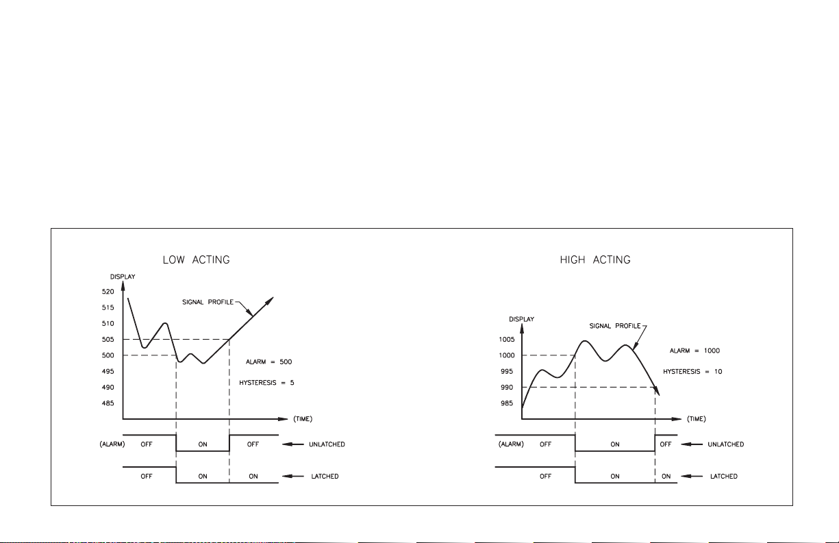
ALARM TIMING DIAGRAMS
trip value (Alarm #2) automatically changes Alarm#1 so that the offset between
Alarm #2 and Alarm #1 remains the same. The following diagrams depict how
the alarms work with both “HI” and “LO” acting set-ups.
Programming of the alarms can be done in the normal programming mode
“Pro 6”or the unit can be programmed so that the valuescan only be changed in
the “quick programming” mode.
If the display should indicate “OLOLOL” the alarms willdeenergize, whether
they are latched or unlatched.
Note: Alarm “COMM.” (TBB #8) must be kept isolated from analog “-”
-25-

RE-TRANSMITTED ANALOG OUTPUT (Optional)
The re-transmitted analog output option transmits a digitally programmable 4
to 20 mA or 0 to 10 VDC signal to drive chart recorders, remote indicators and
controllers. The option is contained on the upper PCB and has two outputs,
“ANALOG-” (Terminal #10) and “ANALOG+” (Terminal #11) and is
self-powered (active) with a compliance of 10 VDC. The analog “-” output is
isolated from thesignal inputcommon, eliminating problems from ground loops.
Programming of the option is performed in “Pro 8” of the normal programming
mode. Display values are simply keyed in to provide a 4 mA or 0 VDC output,
“AN-LO”, and a 20 mA or 10 VDC output, “AN-HI”. The analog output then
follows the assigned value and as such will update every measurement cycle.
ANALOG OUTPUT DIAGRAMS
Nonstandard current or voltage ranges can be supported by calculating the slope
and intercept of the display/output and calculating the required display values at
4 mA or 0 VDC and 20 mA or 10 VDC. Reverse action can be achieved by
programminga “high” display value for“AN-LO” and a “low”display value for
“AN-HI”.
If the display should indicate “OLOLOL” the analog output will go to 20 mA
or 10 VDC.
Note: Analog “-” must be kept isolated from alarm Common (TBB #8).
-26-

ANALOG OUTPUT CALIBRATION
Although the analog output has been calibrated at the factory, zero and span
adjustments are provided to compensate for small offsets and drifts. If excessive
drift is noticed, the following calibration procedure may be performed.
Scale the analog output by entering arbitrarily larger display value for
“AN-HI” then for “AN-LO” in “PRO 8”.
Note: Set the analog output source assignment for input.
4to20mA
Exit the programming mode and apply a signal to the input of the indicator so
that the display reading is below that of the value entered for “AN-LO”. Adjust
the zero potentiometer (right side) so that exactly 4.00 mA flows, as verified by
an accurate ammeter. Next, apply a signal to the indicator so that the display
reading is above that of the value entered for “AN-HI”. (See Appendix “B” for
maximum input.) Adjust the span potentiometer (left side) so that 20.00 mA is
flowing. Repeat the zero and span adjustments until both are accurate. Analog
output calibration is complete.
0to10VDC
Exit the programming mode and apply a (temperature)/(resistance) to the
input of the indicator so that the display reading is belowthat ofthe valueentered
for “AN-LO”. Adjust the zero potentiometer (right side) so that exactly 0.00
VDC flows, as verified by an accurate voltmeter. Next, apply a (temperature)/
(resistance) to the indicator so that the display reading is above that of the value
entered for “AN-HI”. (See Appendix “B” for maximum input.) Adjust the span
potentiometer (left side) so that 10.00 VDC is flowing. Repeat the zero and span
adjustments until both are accurate. Analog output calibration is complete.
-27-

APPENDIX “A” - INSTALLATION & CONNECTIONS
INSTALLATION ENVIRONMENT
Before Installing the IM into the panel, the user should first become familiar
with the unit. It may also be desirable to program the unit for the application.
When programming is complete, all parameters will be saved in nonvolatile
memory. The Program Disable (PGM.DIS.) terminal should be connected to
COMM. to prevent accidental or unauthorized programming changes. The unit
should be installedin alocation thatprovides goodair circulation.Be sure to keep
it away from heat sources (ovens, furnaces, etc.), away from direct contact with
caustic vapors, oils, steam, condensation, or any other process by-products in
which exposure may affect proper operation.
The bezel should be cleaned only with a soft cloth and neutral soap product.
Do NOTuse solvents.Continuous exposure to direct sunlight may accelerate the
aging process of the bezel.
Do not use tools of any kind (screwdrivers, pens, pencils, etc.) to operate the
keypad of the unit.
PANEL INSTALLATION
-28-
The unit meets NEMA 4/IP65 requirements for indoor use, when
properly installed. The units are intended to be mounted into an
enclosed panel with a gasket to provide a water-tight seal. Two
mounting clips and screws are provided for easy installation.
Consideration should be given to the thickness of the panel. A panel
which is too thin may distort and not provide a water-tight seal.
(Recommended minimum panel thickness is 1/8" {3.2mm}.)
After the panel cut-out has been completed and deburred, carefully
slide the gasket over the rear of the unit to the back of the bezel. Insert
the unit into the panel. As depicted in the drawing, install the screws
into the narrow end of the mounting clips. Thread the screws into the
clips until the pointed end just protrudes through the other side. Install
each of the mounting clips by
inserting the wide lip of the clipsinto
the wide end of the hole, located on
either side of the case. Then snap the
clip onto the case. Tighten the
screws evenly to apply uniform
compression, thus providing a
water-tight seal. CAUTION: Only
minimum pressure is required to seal
panel. Do NOT
overtighten screws.

EMC INSTALLATION GUIDELINES
Although this unit is designed with a high degree of immunity to
ElectroMagnetic Interference (EMI), proper installation and wiring methods
must be followed to ensure compatibility in each application. The type of
electrical noise, source or coupling method into the unit may be different for
various installations. In extremely high EMI environments, additional measures
may be needed. The unit becomes more immune to EMI with fewer I/O
connections. Cable length, routing and shield termination are very important and
can mean the difference between a successful or a troublesome installation.
Listed below are some EMC guidelines for successfulinstallation inan industrial
environment.
1. Theunit should be mounted in a metal enclosure, which is properly connected
to protective earth.
a. If thebezel isexposed to high Electro-StaticDischarge (ESD)levels, above
4 Kv, itshould be connected toprotective earth. Thiscan bedone bymaking
sure the metalbezel makesproper contact to the panelcut-out or connecting
the bezel screw with a spade terminal and wire to protective earth.
2. Use shielded (screened) cables for all Signal and Control inputs. The shield
(screen) pigtail connection should be made as short as possible. The
connection point for the shield depends somewhat upon the application.
Listed beloware the recommended methods of connecting the shield, in order
of their effectiveness.
a. Connect the shield only at the panel where the unit is mounted to earth
ground (protective earth).
b. Connect theshield to earth ground atboth endsof thecable, usuallywhen
the noise source frequency is above 1 MHz.
c. Connect the shield to common of the unit and leave the other end of the
shield unconnected and insulated from earth ground.
3. Never run Signal or Control cables in the same conduit or raceway with AC
power lines, conductors feeding motors, solenoids, SCR controls,and heaters,
etc. The cables should be run in metal conduit that is properly grounded. This
is especially useful in applications where cable runs are long and portable
two-way radios are used in close proximity or if the installation is near a
commercial radio transmitter.
4. Signal or Control cables within an enclosure should be routed as far away as
possible from contactors, control relays, transformers, and other noisy
components.
5. In extremely high EMI environments, the use of external EMI suppression
devices, such as ferrite suppression cores, is effective. Install them on Signal
and Control cables as close to the unit as possible. Loop the cable through the
core several times or use multiple cores on each cable for additional
protection. Install line filters on the power input cable to the unit to suppress
power line interference. Install them near the power entry point of the
enclosure. The following EMI suppression devices (or equivalent) are
recommended:
Ferrite Suppression Cores for signal and control cables:
Fair-Rite # 0443167251 (RLC #FCOR0000)
TDK # ZCAT3035-1330A
Steward #28B2029-0A0
Line Filters for input power cables:
Schaffner # FN610-1/07 (RLC #LFIL0000)
Schaffner # FN670-1.8/07
Corcom #1VR3
Note: Reference manufacturer’s instructions when installing a line filter.
6. Long cable runs are more susceptible to EMI pickup than short cable runs.
Therefore, keep cable runs as short as possible.
7. Switching of inductive loads produces high EMI. Use of snubbers across
inductive loads suppresses EMI.
Snubbers:
RLC #SNUB0000
SELECT AC POWER (115/230 VAC)
The AC power to the unit must be selected for either 115 VAC or 230 VAC.
The selector switch is located through an access slot on the side of the case (See
Panel Installation Figure or label on case). The unit is shipped from the factory
with the switch in the 230 VAC position.
Caution: Damage to the unit may occur if the AC selector switch is set
incorrectly.
-29-
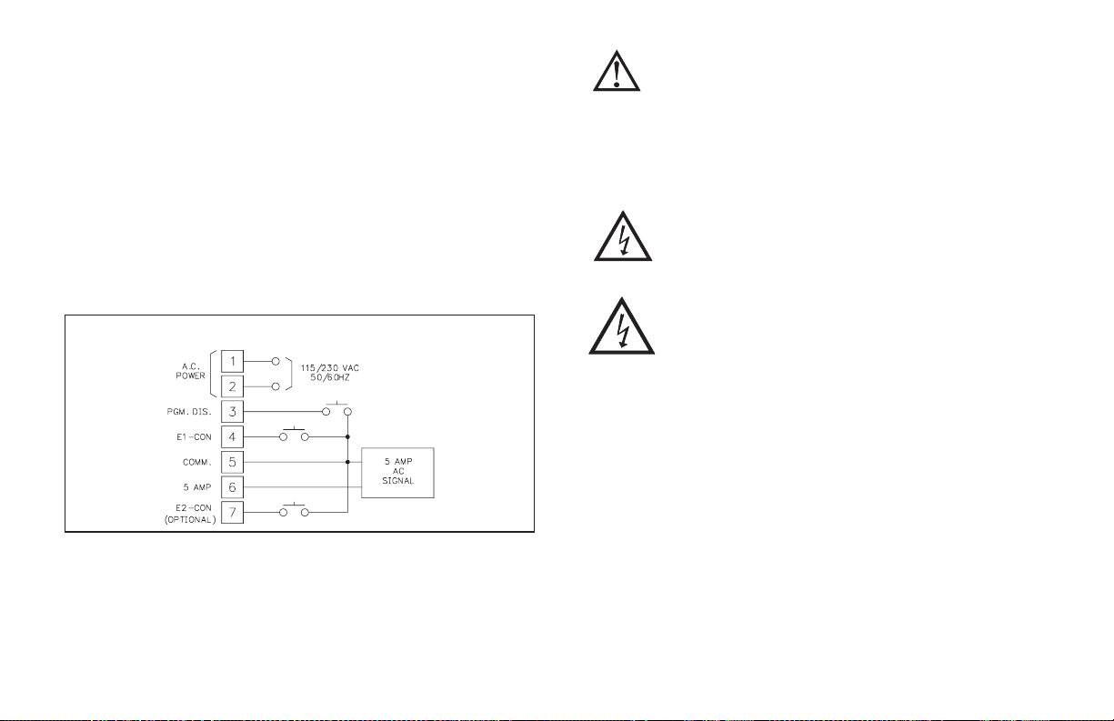
WIRING CONNECTIONS
After the unit has been mechanically mounted, it is ready to be wired. All
wiring connections are made on removable plug-in terminal blocks. There is a
separate terminal block for the bottom board (TBA) and optional top board
(TBB). Allconductors should meet voltage and current ratings for each terminal.
Also cabling should conform to appropriate standards of good installation, local
codes and regulations. It is recommended that power supplied to the unit be
protected by a fuse or circuit breaker.When wiring the unit, remove the terminal
block and use the numbers on the label to identify the position number with the
proper function. Strip the wire, leaving approximately 1/4" bare wire exposed
(stranded wires should be tinned with solder). Insert the wire into the terminal
and tighten down the screw until the wire is clamped tightly. Each terminal can
accept up to one 14-gage,two 18-gageor four 20-gage wire(s).After theterminal
block is wired, install it into the proper location on the PC board. Wire each
terminal block in this manner.
Basic Connection
CAUTION: Disconnectpower to all unit terminals before removing
terminal blocks. This includes deenergizing the current transformer
primary circuit.
SIGNAL WIRING
AC signal wires are connected to TBA #5 and 6. If AC signal current greater
than 5 ampsAC is going to be applied,the appropriate sizeslow blow fuse should
be installed.
CAUTION:TheIMHisintendedtobeusedwitha5ampAC
current transformer. Use without a current transformer will place
the meter’s input and output terminals at the measured circuit’s
potential.
CAUTION: It is recommended that the current transformer be
internally protected or that a voltage clamping circuit be provided,
preventing dangerous high voltage across the CT secondary
windings in case of accidental opening of the secondary output
leads when the primary is energized. In order to prevent risk of
electric shock ensure CT is installed according to local NEC
regulations for installation of current instrument transformers.
USER INPUT WIRING
User inputs (PGM.DIS., E1-CON, and optional E2-CON) are digital inputs
that are active when connected to TBA #5 Common. Any form of mechanical
switch, sinking collector logic with less than 0.7 V saturation may be used. The
use of shielded cable is recommended. Follow the EMC Installation Guidelines
for shield connection.
POWER WIRING
Primary AC power is connected to TBA #1 and 2 (marked VAC 50/60 Hz,
located on the left hand side of the bottom terminal block, as you face the rear of
the meter). To reduce the chance of noise spikes entering the AC line and
affecting the indicator, the ACpower should be relatively “clean”and within the
specified +/-10% variation limit. Drawing power from heavily loaded circuits or
circuits which also power loadsthat cycle on and off,(contactors, relays, motors,
machinery, etc.) should be avoided.
OUTPUT WIRING
RELAY CONNECTIONS
To prolong contact life and suppress electrical noise interference due to the
switching of inductive loads, it is good installation practice to install a snubber
across the contactor. Follow the manufacturer’s instructions for installation.
Note: Snubber leakage current can cause some electro-mechanical devices to be
held ON.
-30-
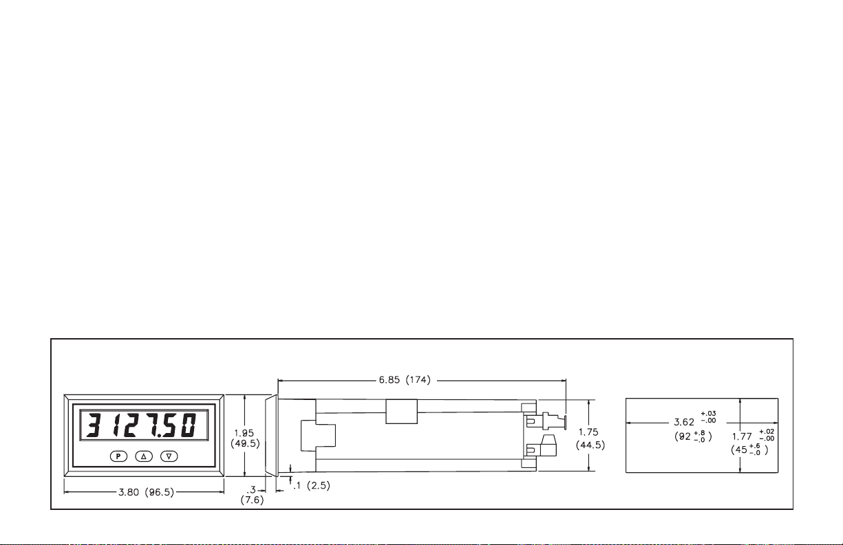
APPENDIX “B” - SPECIFICATIONS AND
DIMENSIONS
1. DISPLAY: 6-digit, 0.56" (14.2 mm) High LED. Flashing display during
totalizer overflow. “......” displayed during input display out of range.
“OLOLOL” is displayed during input overload, which is any current greater
than 5.3 amps AC.
2. POWER REQUIREMENTS:
AC Power: Switch Selectable 115/230 VAC, ±10%, 50/60 Hz, 14 VA
3. CONTROLS: Three front panel push buttonsfor modifying alarm values and
indicator set-up. Two external inputs for disabling the front panel and
controlling programmable functions.
4. INPUT RANGE: 0.000 to 5.300 A AC @ 25 to 400 Hz.
5. INPUT RESISTANCE: 0.02 W ;2W.
6. MAXIMUM SHUNT CURRENT: 50 A for 1 second;
10 AMPS continuous.
Caution: In circuits where fault currents can exceed the maximum shunt
current, a fast blow fuse should be installed in series with the input signal.
Otherwise, a slow blow 10 amp fuse is recommended which will allow for
start-up over current situations, while still protecting the instrument.
7. ACCURACY: (23°C, 85% R.H.)(45-500 Hz) ±(0.5% of reading +5 digits)
8. RESOLUTION: 1mA
9. PROGRAMMABLE DISPLAY READING RANGE:
-99999 to 999999.
10. SIGNAL CONNECTION: 2-Wire
11. READING RATE: 2.5 readings/second.
12. RESPONSE TIME: 2 seconds to settle for step input (increases with
programmable digital filtering).
13. TOTALIZER: Front panel button for input/total display select.
Programmable time-base, scale factor (0.001 to 100.000) and low-end cutout.
Max. Response Time = 0.2 seconds.
14. E1-CON & E2-CON: External remote inputs that allow activation of
various functions (reset total, peak indicator mode, trigger mode, etc). V
0.8 V
MAX;VIH
=2.0V
; Max Response Time = 0.2 seconds.
MIN
IL
15. ENVIRONMENTAL CONDITIONS:
Operating Temperature: 0° to 50°C
Storage Temperature: -40° to 80°C
Temperature Coefficient: +/- 200 ppm/°C
Operating and Storage Humidity: 85% max. relative humidity
(non-condensing) from 0°C to 50°C.
Altitude: Up to 2,000 meters
=
DIMENSIONS In inches (mm)
Note: Recommended minimum clearance (behind the panel) for
mounting clip installation is 2.1" (53.3)H x 5.5" (140)W.
-31-
PANEL CUT-OUT

16. ALARMS (Optional):
Solid State: Two, isolated, sinking open collector NPN transistors acting in
parallel with relays.
Imax = 100 mA; V
= 1 V @ 100 mA; V
SAT
MAX
= 30 VDC.
Relays:
Type: Form C (2)
Max. Rating: 5 A 120/240 VAC or 28 VDC (resistive load),1/8HP
120 VAC (inductive load).
Relay Life Expectancy: 100,000 cycles at Max. Rating. (As load level
decreases, life expectancy increases.)
17. ANALOG OUTPUT (Optional): Digital scaling and offsetting.
4to20mA:
Accuracy: 0.1% of full scale
Resolution: 12 bits
Compliance Voltage: 10 VDC (500 W max. loop impedance)
0to10VDC:
Accuracy: ± (0.1% of reading +35 mV)
Resolution: 12 bits
Min. Load Resistance: 10 KW (1 mA max.)
18. LINEARIZER/PEAK/VALLEY/TARE (optional):
9-segment multiple slope scaling for non-linear inputs. Peak and Valley
recording. Signal re-zero (tare).
19. CONSTRUCTION: Die-cast metal front bezel that meets NEMA 4/IP65
requirements for indoor usewhen properly installed. Case body is black, high
impact plastic (panel gasket and mounting clips included). Installation
Category II, Pollution Degree 2.
20. CONNECTION: Removable terminal blocks
21. CERTIFICATIONS AND COMPLIANCES:
SAFETY
IEC 1010-1, EN 61010-1: Safety requirements for electrical equipment
for measurement, control, and laboratory use, Part 1.
IP65 Enclosure rating (Face only), IEC 529
Type 4 Enclosure rating (Face only), UL50
ELECTROMAGNETIC COMPATIBILITY
Immunity to EN 50082-2
Electrostatic discharge EN 61000-4-2 Level 2; 4 Kv contact
Level3;8Kvair
Electromagenetic RF fields EN 61000-4-3 Level 3; 10 V/m
1
2
80 MHz - 1 GHz
Fast transients (burst) EN 61000-4-4 Level 4; 2 Kv I/O
Level3;2Kvpower
RF conducted interference EN 61000-4-6 Level 3; 10 V/rms
150 KHz - 80 MHz
Power frequency magnetic fields EN 61000-4-8 Level 4; 30 A/m
Emissions to EN 50081-2
RF interference EN 55011 Enclosure class A
Notes:
Power mains class A
1. Metalbezel of unit connected with ground lead from rear bezel screw tometal
mounting panel.
2. Self-recoverable loss of performance during EMI disturbance at 10 V/m:
process signal deviation less than 2% of full scale.
analog output signal deviation less than 8% of full scale.
For operation without loss of performance:
Unit is mounted in a metal enclosure (Buckeye SM7013-0 or equivalent)
I/O and power cables are routed in metal conduit connected to earth
ground.
Refer to the EMC Installation Guidelines section of the manual for additional
information.
22. WEIGHT: 1.2 lbs (0.5 kg).
-32-

APPENDIX “C” - TROUBLESHOOTING GUIDE
The majority ofall problems withthe indicatorcan betraced toimproper connectionsor improper programming
set-ups. Be sure all connectionsare cleanand tight and check the programming set-ups for correctdata. For further
technical assistance, contacttechnical support atthe numbers listed onthe back coverof theinstruction manual.
PROBLEM POSSIBLE CAUSE REMEDIES
NO DISPLAY 1. Power off, improperly connected, or brown-out.
“PPPPPP” IN DISPLAY 1. Program data error. 1. Press “P” and Check data set-ups.
FLASHING DISPLAY 1. Totalizer overflow. 1. Reset totalizer.
“......” IN DISPLAY 1. Input display out of range. 1a. Check unit scaling.
2. Loss of data set-ups. 2a. Check data set-ups.
DISPLAY WANDERS 1. Loss of data set-ups. 1a. Check data set-ups.
JITTERY DISPLAY 1. Electrical “Noise” process or sensor lines. 1a. Increase digital filtering.
2. Process inherently unstable. 2. Dampen process to eliminate oscillations.
“OLOLOL” IN DISPLAY 1. Input overload. 1. Check input levels.
-33-
1a. Check wiring.
b. Verify power.
b. Check for electrical disturbance.
b. Check for electrical disturbance.
c. Disconnect and reconnect power.
b. Disconnect and reconnect power.
c. Check for electrical disturbance.
b. Increase display rounding increment.
c. Re-route signal wires.

APPENDIX “D” - PROGRAMMABLE FUNCTIONS
Programming of the indicator is divided intomodular steps.Each module is a
short sequence of data entries. The front panel buttons “UP” and “DOWN”,
(shown as“arrows” on the front panel)are used to change thedata and set-ups,
while the “P” buttonisusedtosave or enter the data. After pressing “P” which
gains entry into the programming mode, the programming modules are
identified by the message “Pro” and a number in the display. “UP” and
“DOWN” are used to select the desired programming module and“P” isused to
enter it. All of the subsequent programming steps follow the same procedure.
The rear terminal labeled “PGM. DIS.” must be ungrounded to gain access to
programming. The following table lists the programming steps.
“Pro 0” - RETURN TO MEASUREMENT MODE
“Pro 1” - SCALE UNIT BY APPLYING SIGNAL
“dECPNt” - Enter decimal point for scaled display
“round” - Enter rounding factor and trailing zeros for scaled display
“SCALE” - *
“dSP 1” - Enter display reading for scaling point #1
“INP 1” - Apply signal level for scaling point #1
“dSP 2” - Enter display reading for scaling point #2
“INP 2” - Apply signal level for scaling point #2
“SEGt” - *
“Pro 2” - SCALE UNIT BY KEY-IN SIGNAL LEVEL
“dECPNt” - Enter decimal point for scaled display
“round” - Enter rounding factor and trailing zeros for scaled display
“SCALE” - *
“dSP 1” - Enter display reading for scaling point #1
“INP 1” - Enter signal level for scaling point #1
“dSP 2” - Enter display reading for scaling point #2
“INP 2” - Enter signal level for scaling point #2
“SEGt” - *
“Pro 3” - PROGRAM FUNCTIONS ACCESSIBLE WITH FRONT PANEL
LOCKOUT ENGAGED
“dSP AL” - Enable display alarms
“ENt AL” - Enable Enter alarms **
“dSPHYS” - Enable display hysteresis
“ENtHYS” - Enable Enter hysteresis **
“rSt AL” - Enable reset latched alarms
“dSPbUF” - Enable display of peak/valley readings
“rStbUF” - Enable reset of peak/valley readings **
“SELdSP” - Enable switching display between input and total
“rSttOt” - Enable reset total
“tArE” - Enable re-zero (tare) of input signal
* - Entire sequence for this modular step is not shown
(see respective programming module for further details).
** - This sequence may be subject to being locked-out due to
other programmed sequences.
-34-

APPENDIX “D” - PROGRAMMABLE FUNCTIONS (Cont’d)
“Pro 4” - PROGRAM DIGITAL FILTERING AND REMOTE INPUT
FUNCTION
“FILtEr” - Enter level of digital filtering
0 - no digital filtering
1 - normal filtering
2 - increased filtering
3 - maximum filtering
“E1-CON” - Enter function of remote switch (E1-CON)
0 - re-zero input
1 - reset total
2 - reset and gate totalizer
3 - gate totalizer
4 - display hold
5 - reset peak/valley
6 - reset peak and start peak indicator
7 - reset valley and start valley indicator
8 - reset latched alarms
9 - reset all alarms
10 - toggle display between input and total
11 - re-zero input and totalize the tared values
12 - display hold with tare
13 - instrument reading synchronization
“E2-CON” - Same functions as E1-CON
“Pro 5” - PROGRAM TOTALIZER
“dECPNt” - Enter decimal point for totalizer
“tbASE” - Enter time base
0 - second
1 - minute
2 - hour
“SCLFAC” - Enter multiplying scale factor
“Lo-cut” - Enter low-signal cut out
“Pro 6” - PROGRAM ALARMS
“trAc” - Enable alarm value tracking
“dISP” - Enable display alarm annunciators
“LAtC-1” - Enable alarm #1 latching
“ASN-1” - Enter alarm #1 trigger source (input or total)
“AL-1” - Enter alarm #1 value
“HYS-1” - Enter hysteresis value for alarm #1
“Act-1” - Enter alarm #1 action (high or low)
“LAtC-2” - Enable alarm #2 latching
“ASN-2” - Enter alarm #2 trigger source (input or total)
“AL-2” - Enter alarm #2 value
“HYS-2” - Enter hysteresis value for alarm #2
“Act-2” - Enter alarm #2 action (high or low)
“Pro 7” - NOT USED
“Pro 8” - PROGRAM RE-TRANSMITTED ANALOG OUTPUT
“ASIN” - Select source of analog output (input or total)
“AN-Lo” - Enter 4 mA or 0 VDC display value
“AN-HI” - Enter 20 mA or 10 VDC display value
“Pro 9” - SERVICE OPERATION
(Protected by access codes)
“Code 48” - Basic input calibration
“Code 66” - Reset programming to factory configuration
-35-

APPENDIX “E” - ORDERING INFORMATION
TOTALIZER/
MODEL NO. DESCRIPTION
IMH
For information on Pricing, Enclosures, and Panel Mount Kits, refer to the RLC Catalog or contact your local
RLC distributor.
5 AMP AC Intelligent
Current Meter
LINEARIZER/
PEAK/VALLEY
TARE/E2-CON
NO NO NO IMH40060
NO YES NO IMH40062
YES NO NO IMH43060
YES YES NO IMH43062
YES YES 4 to 20 mA IMH43066
YES YES 0 to 10 VDC IMH43068
DUAL
ALARM
OUTPUT
ANALOG
OUTPUT
PART
NUMBERS
115/230 VAC
-36-

LIMITED WARRANTY
The Company warrants the products it manufactures against defects in materials and workmanship for a period limited to two years from the date of shipment, provided the products have
been stored, handled, installed, and used under proper conditions. The Company’s liability under
this limited warranty shall extend only to the repair or replacement of a defective product, at The
Company’s option. The Company disclaims all liability for any affirmation, promise or representation with respect to the products.
The customer agrees to hold Red Lion Controls harmless from, defend, and indemnify RLC
against damages, claims, and expenses arising out of subsequent sales of RLC products or products containing components manufactured by RLC and based upon personal injuries, deaths,
property damage, lost profits, and other matters which Buyer, its employees, or sub-contractors
are or may be to any extent liable, including without limitation penalties imposed by the
Consumer Product Safety Act (P.L. 92-573) and liability imposed upon any person pursuant to
the Magnuson-Moss Warranty Act (P.L. 93-637), as now in effect or as amended hereafter.
No warranties expressed or implied are created with respect to The Company’s products
except those expressly contained herein. The Customer acknowledges the disclaimers and limitations contained and relies on no other warranties or affirmations.

Red Lion Controls
20 Willow Springs Circle
York PA 17406
Tel +1 (717) 767-6511
Fax +1 (717) 764-0839
Red Lion Controls BV
Basicweg 11b
NL - 3821 BR Amersfoort
Tel +31 (0) 334 723 225
Fax +31 (0) 334 893 793
IMH/IM-J 7/06
DRAWING NO. LP0206
Red Lion Controls AP
31, Kaki Bukit Road 3,
#06-04/05 TechLink
Singapore 417818
Tel +65 6744-6613
Fax +65 6743-3360
 Loading...