

Page 1
(85.1)
3.35
(89)
3.5
.39
(10)
(25)
.98
COMM
COMM
PWR
TXD
RS485
M2869X
MADE IN U.S.A.
RED LION CONTROLS
57600 BAUD
115200 BAUD
38400 BAUD
OFF 4 WIRE/ ON 2 WIRE
OFF 422/ ON 485
120Ω TERMINATION
OFF 4 WIRE/ ON 2 WIRE
OFF DCE/ ON DTE
OFF DTE/ ON DCE
OFF DTE/ ON DCE
OFF DCE/ ON DTE
OFF 422/ ON 485
YORK, PA.
MODEL ICM5
MUST BE SET
IN GROUPS
SWITCHES
*
*
*
*
*
@ 125mA MAX.
9-26VDC CLASS 2
19200 BAUD
9600 BAUD
PULL UP
PULL DOWN
RS232
10
6
213
5
4
798
NC
1
34526
7
SPLY
PWR
ON
+ VDC
422
485/
LEDS
ON
RXA
RXB
TXB
TXA
2
1
4
3
5
6
7
Bulletin No. ICM5-D
Drawing No. LP0529
Released 09/09
Tel +1 (717) 767-6511
Fax +1 (717) 764-0839
www.redlion.net
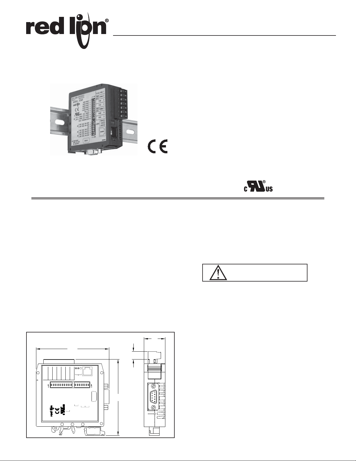
MODEL ICM5 – THREE WAY ISOLATED SERIAL CONVERTER MODULE
(RS-232C/RS-485)
ALLOWS COMMUNICATIONS BETWEEN RS-232 CONTROL
EQUIPMENT AND PRODUCTS WITH RS-422/RS-485 SERIAL
COMMUNICATIONS
THREE WAY ISOLATION PROTECTS SERIAL EQUIPMENT FROM
GROUND LOOPS (1000 VDC)
AUTOMATIC RS-485 DRIVER CONTROL
DIP SWITCH SELECTABLE BAUD RATES 9600, 19200, 38400,
57600, 115200
WIDE DC INPUT POWER RANGE (+9 to 26 VDC)
HALF DUPLEX (RS-485) AND FULL DUPLEX (RS-422)
LED INDICATION FOR RXD, TXD, and POWER
9 PIN D-SUB CONNECTOR FOR RS-232 CONNECTION
SWITCHABLE TERMINATION AND BIASING RESISTORS
MODULAR RJ JACK OR SCREW TERMINAL FOR RS-485
CONNECTION
UNIVERSAL MOUNTING FOOT FOR DIN RAIL INSTALLATION
SELECTABLE DTE & DCE OPERATION WORKS WITH ANY
RS-232 CABLE
UL Recognized Component,
File # E179259
DESCRIPTION
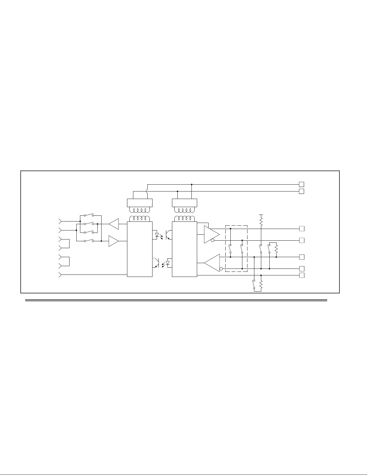
The ICM5 Serial Converter Module provides the capability of interfacing
equipment with RS-485 serial communications to equipment with RS-232
communications while providing three way isolation. Data format of the
RS-232 and RS-485 equipment must be the same.
The unit can be configured for full duplex (RS-422), or half duplex (RS-485)
operation. In half duplex mode, the RS-485 driver is automatically enabled
using the leading edge of the first character that is received on the RS-232 side.
After the last character is received, the converter waits one character time (at the
selected baud rate) to disable the RS-485 driver.
An external DC power source (+9 to 26 VDC) is required to power the ICM5.
The external power source and RS-485 communications connections are made
via a 7-position removable terminal block located on the front of the module. A
modular RS-485 connector is also provided for fast and efficient connection to
other Red Lion devices that use a modular connector. The RS-232 connection is
provided via a standard D-SUB 9-pin male connector. The ICM5 can be
configured for DTE or DCE operation, allowing the use of modem or nullmodem cables.
There are 3 LEDs that can be viewed from the front of the converter module.
A green power LED indicates power is on, a red RS-232 TXD LED flashes
when the module is transmitting, and a green RS-232 RXD LED flashes when
the module is receiving.
DIMENSIONS In inches (mm)
The unit is equipped with a universal mounting foot for attachment to
standard DIN style mounting rails, including top hat profile rail according to EN
50 022 - 35x7.5 and 35x15, and G profile rail according to EN 50 035 - G32.
SAFETY SUMMARY
All safety related regulations, local codes and instructions that appear in the
manual or on equipment must be observed to ensure personal safety and to
prevent damage to either the instrument or equipment connected to it. If
equipment is used in a manner not specified by the manufacturer, the protection
provided by the equipment may be impaired.
Read complete instructions prior to
installation and operation of the unit.
CAUTION:
SPECIFICATIONS
1. POWER: +9 to 26 VDC @ 125 mA maximum. 85 mA typical
Power Supply must be Class 2 or SELV rated.
2. RS-232 VOLTAGES:
Receive Data Pin: 30 VDC max.
Mark Condition: 0.8 VDC
Space Condition: 2.4 VDC
Transmit Data Pin:
Mark Condition: -8 VDC (typ.)
Space Condition: 8 VDC (typ.)
3. RS-485 VOLTAGES:
Differential Output Voltage: 5VDC max. under no load
Differential Input Voltage: 5VDC max.
Mark Condition: -0.2 VDC
Space Condition: 0.2 VDC
RS-485 Drive Capability: Up to 32 RS-485 receivers connected in parallel
RS-485 Drive Disable Time: one character time (at the set baud rate)
4. MAXIMUM CABLE LENGTH:
RS-232: 50 feet (15.24 m)
RS-485: 4000 feet (1219.2 m)
5. BAUD RATE: 9600 min., 115200 max.
6. ISOLATION: 1000 VDC
7. ENVIRONMENTAL CONDITIONS:
Operating Temperature Range: 0 to 50C.
Storage Temperature: -40 to + 75C
Operating and Storage Humidity: 85% max. relative humidity
(non-condensing) from 0 to 50C
1
Page 2
Vibration according to IEC 68-2-6: Operational 5 to 150 Hz in X, Y, Z
8
5
4.7K
RXB
COMMON
6
5
2
4
6
7
3
2
9 PIN "D"
CONNECTOR
1
POWER IN
RS232
SWITCHES
BAUD RATE
RD
DTE/DCE
SWITCHES
TD
RS485
CONTROL
TX
RX
4 WIRE
2 WIRE/
4.7K
+5V
TXA
4
RXA
TXB
TERMINATION
120
Ω
7
3
+VDC
COMM
TX/RX
TX/RX
DTR
DSR
RTS
CTS
COMM
direction for 1.5 hours, 2 g’s.
Shock according to IEC 68-2-27: Operational 30 g’s, 11 msec in 3 directions.
Altitude: Up to 2000 meters
8. CERTIFICA TIONS AND COMPLIANCES:
SAFETY
UL Recognized Component, File #E179259, UL3101-1, CSA 22.2 No. 1010-1
Recognized to U.S. and Canadian requirements under the Component
Recognition Program of Underwriters Laboratories, Inc.
IECEE CB Scheme Test Report #01ME11540-0702001
Issued by Underwriters Laboratories, Inc.
IEC 61010-1, EN 61010-1: Safety requirements for electrical equipment
for measurement, control, and laboratory use, Part 1.
ELECTROMAGNETIC COMPATIBILITY
Immunity to EN 50082-2
Electrostatic discharge EN 61000-4-2 Level 2; 4 Kv contact
Level 3; 8 Kv air
1
Electromagnetic RF fields EN 61000-4-3 Level 3; 10 V/m
80 MHz - 1 GHz
Fast transients (burst) EN 61000-4-4 Level 4; 2 Kv I/O
Level 3; 2 Kv power
RF conducted interference EN 61000-4-6 Level 3; 10 V/rms
150 KHz - 80 MHz
Emissions to EN 50081-1
RF interference EN 55022
Enclosure class B
Power mains class B
BLOCK DIAGRAM
Note:
1. This device was designed for installation in an enclosure. To avoid
electrostatic discharge to the unit in environments with static levels above
4 Kv, precautions should be taken when the device is mounted outside an
enclosure. When working in an enclosure, (ex. making adjustments, setting
switches etc.) typical anti-static precautions should be observed before
touching the unit.
Refer to EMC Installation Guidelines for additional information.
9. CONSTRUCTION: Case body is black, high impact plastic. Installation
Category I, Pollution Degree 2.
10. MOUNTING: Standard DIN rail top hat (T) profile rail according to
EN50022- 35 X 7.5 and 35 X 15
11. WEIGHT: 3.3 oz. (93.6 g)
1
EMC INSTALLATION GUIDELINES
Although this unit is designed with a high degree of immunity to
ElectroMagnetic Interference (EMI), proper installation and wiring methods
must be followed to ensure compatibility in each application. The type of
electrical noise, source or coupling method into the unit may be different for
various installations. In extremely high EMI environments, additional measures
may be needed. Cable length, routing and shield termination are very important
and can mean the difference between a successful or a troublesome installation.
Listed below are some EMC guidelines for successful installation in an
industrial environment.
1. DC power to the unit should be relatively clean and within the specified
limits. Connecting power to the unit from circuits that power inductive loads
that cycle on and off, such as contactors, relays, motors, etc., should be
avoided. This will reduce the chance of noise spikes entering the DC power
2. The shield (screen) pigtail connection should be made as short as possible.
connection and affecting the unit.
The connection point for the shield depends somewhat upon the application.
Listed below are the recommended methods of connecting the shield, in
order of their effectiveness.
a. Connect the shield only at the unit to earth ground (protective earth).
b. Connect the shield to earth ground at both ends of the cable, usually when
the noise source frequency is above 1 MHz.
c. Connect the shield to common of the unit and leave the other end of the
shield unconnected and insulated from earth ground.
3. Never run Signal cables in the same conduit or raceway with AC power lines,
conductors feeding motors, solenoids, SCR controls, and heaters, etc. The
cables should be run in metal conduit that is properly grounded. This is
especially useful in applications where cable runs are long and portable twoway radios are used in close proximity or if the installation is near a
commercial radio transmitter.
4. Signal cables within an enclosure should be routed as far away as possible
from contactors, control relays, transformers, and other noisy components.
5. In extremely high EMI environments, the use of external EMI suppression
devices, such as ferrite suppression cores, is effective. Install them on Signal
cables as close to the unit as possible. Loop the cable through the core several
times or use multiple cores on each cable for additional protection.
Install line filters on the power input cable to the unit to suppress power line
interference. Install them near the power entry point of the enclosure. The
following EMI suppression devices (or equivalent) are recommended:
Ferrite Suppression Cores for signal cables:
Fair-Rite # 0443167251 (RLC #FCOR0000)
TDK # ZCAT3035-1330A
Steward #28B2029-0A0
Line Filters for input power cables:
Schaffner # FN610-1/07 (RLC #LFIL0000)
Schaffner # FN670-1.8/07
Corcom #1VR3
Note: Reference manufacturer’s instructions when installing a line filter.
6. Long cable runs are more susceptible to EMI pickup than short cable runs.
Therefore, keep cable runs as short as possible.
2
Page 3

LEDS
*
SWITCHES
IN GROUPS
MUST BE SET
*
*
OFF DCE/ ON DTE
RS232
OFF DTE/ ON DCE
OFF DTE/ ON DCE
OFF DCE/ ON DTE
*
6
5
7
ON
PULL UP
PULL DOWN
OFF 4 WIRE/ ON 2 WIRE
OFF 4 WIRE/ ON 2 WIRE
120Ω TERMINATION
38400 BAUD
115200 BAUD
57600 BAUD
OFF 422/ ON 485
OFF 422/ ON 485
*
9
1
NC23
4
10
6
7
8
3
4
5
RED LION CONTROLS
MODEL ICM5
YORK, PA.
9600 BAUD
19200 BAUD
MADE IN U.S.A.
9-26VDC CLASS 2
@ 125mA MAX.
1
2
ON
M2869X
RS485
TXD
RXD
PWR
RXA 7
COMM
485/
RXB
422
TXA
5
6
4
COMM
TXB
PWR
SPLY
+ VDC
2
3
1
SIDE VIEW OF ICM5
ON
115200 BAUD
57600 BAUD
38400 BAUD
PULL DOWN
9600 BAUD
19200 BAUD
*****
PULL UP
6
543
7
*
1
2
*
OFF DTE/ ON DCE
OFF DTE/ ON DCE
OFF DCE/ ON DTE
OFF DCE/ ON DTE
OFF 422/ ON 485
OFF 422/ ON 485
120Ω TERMINATION
OFF 4 WIRE/ ON 2 WIRE
OFF 4 WIRE/ ON 2 WIRE
4
*
*
NC 3
2
1
***
9
8
10
567
JUMPERED
INTERNALLY
TX2
SIG COM
3
5
RX
TYPICAL RS-232 CONNECTIONS
ON
DCE
RXTXSIG COM
2
3
5
INTERNALLY
JUMPERED
1
9600 BAUD
Note:
Connect shield (drain wire) to earth ground.
235
4
57600 BAUD
38400 BAUD
19200 BAUD
*******
*
6
7PULL UP
8
PULL DOWN
115200 BAUD
OFF 4 WIRE/ ON 2 WIRE
DTE
Note:
Connect shield (drain wire) to earth ground.
***
*
1
9
2
4
10
NC 3
OFF 422/ ON 485
OFF 422/ ON 485
OFF DCE/ ON DTE
OFF DCE/ ON DTE
120Ω TERMINATION
OFF 4 WIRE/ ON 2 WIRE
- Application Dependent
*
- Application Dependent
*
ON
765
OFF DTE/ ON DCE
OFF DTE/ ON DCE
DIP SWITCH SETTINGS
Top Bank of 10 Switches
Switches 1-5 - BAUD
Select the appropriate baud rate. This
adjusts the time delay for the automatic
RS-485 driver controller. Only one of the
DEFAULT SETTINGS
BAUD RATE 9600
DCE
2 WIRE \ RS-485
NO TERMINATION
NO PULL-UP OR PULL DOWN
baud switches should be in the ON position.
Switches 6-7 - PULL UP / PULL DOWN
These switches connect 4.7 K biasing resistors to the A and B lines of the
485 receiver. To minimize loading of the network, these should only be used if
no other device in the system provides biasing.
Switches 8-9 - OFF 4 WIRE / ON 2 WIRE
These switches can be used to internally jumper the A and B lines of the
RS-485 driver and receiver together. This allows 2-wire operation without the
use of external jumper wires. To use the RJ-11 connector, the ICM5 must be in
2-wire mode. Both switches should be in the same position.
Switch 10 - 120 TERMINATION
This switch connects a 120 resistor across the A and B lines of the RS-485
receiver. The use of the resistor prevents signal reflection, or echoing, at high
baud rates, over long distances. This should only be turned on if the ICM5 is
the first, or last, device in a multi-drop network that is experiencing reflection
due to long cable distances.
Bottom Bank of 7 Switches
Switches 1-2 - OFF 422 / ON 485
These switches enable and disable the automatic RS-485 driver control. In
the 422 position, the driver is always enabled, allowing 4-wire full duplex
operation. In the 485 position, the driver is enabled as soon as characters are
received on the RS-232 side. When the RS-485 driver has transmitted the last
character, it waits one character time (at the selected baud rate), and then enters
a high-impedance state. The receiver is also enabled and disabled in a similar
fashion to prevent transmitted characters from being echoed back. This allows
2-wire, half-duplex operation, without the use of handshake lines. Both
switches should be in the same position.
Switch 3 - N/C
No Connection
Switches 4-7 - OFF DCE / ON DTE
These switches configure the RS-232 port to act as a DCE or DTE device.
With all of the switches in the DCE position, pin 2 of the DB-9 connector is the
RS-232 receiver, and pin 3 is the RS-232 transmitter. DTE configures pin 2 as
the transmitter, and pin 3 as the receiver. These switches allow the use of
modem or null-modem cables. All of these switches should be in the DCE or
DTE position. No other combinations are valid.
TYPICAL RS-422 CONNECTIONS
A
TX
RX
ON
4.7K
4.7K
*
*
1
3
2
9600 BAUD
19200 BAUD
38400 BAUD
B
+5V
*
*
4
57600 BAUD
115200 BAUD
6
PULL DOWN
***
9
785
PULL UP
OFF 4 WIRE/ ON 2 WIRE
OFF 4 WIRE/ ON 2 WIRE
Notes:
1. Connect shield (drain wire) to earth ground.
2. RS-422 polarity: Terminal “A” is negative with respect to Terminal “B” in the
mark (logic 1) condition.
120Ω
*
1
10
OFF 422/ ON 485
120Ω TERMINATION
4
TRANSMIT DATA
TRANSMIT DATA
3
A
7
RECEIVE DATA
B
6
RECEIVE DATA
5
SIGNAL COMMON
***
NC
OFF 422/ ON 485
OFF DCE/ ON DTE
OFF DCE/ ON DTE
ON
*
6
74523
OFF DTE/ ON DCE
OFF DTE/ ON DCE
- Application Dependent
*
TYPICAL RS-485 CONNECTIONS
+5V
Note:
Connect shield (drain wire)
to earth ground.
3
TX/RX
ON
***
213
9600 BAUD
19200 BAUD
38400 BAUD
4.7K
***
6
5
4
57600 BAUD
PULL DOWN
115200 BAUD
7
PULL UP
4.7K
*
9
8
10
120Ω TERMINATION
OFF 4 WIRE/ ON 2 WIRE
OFF 4 WIRE/ ON 2 WIRE
*
1
OFF 422/ ON 485
OFF 422/ ON 485
120Ω
***
6
3NC25
4
OFF DTE/ ON DCE
OFF DCE/ ON DTE
OFF DCE/ ON DTE
A
7
B
6
SIGNAL COMMON
5
ON
*
7
OFF DTE/ ON DCE
- Application Dependent
*
Page 4

TYPICAL CONNECTION FOR RS-485 DEVICES
RS485
+VDC
PWR
SPLY
485/
422
TXB
TXA
RXB
RXA
COMM
COMM
COMM.
1+ VDC
2
3
4
5
6
7
TC
COMM
RTD
AC~~AC
312
31 2
LEGEND
- B(-)
12
- A(+)
13
- COMMON
14
- N/C
15
USER INPUTS
COMM132N/C
N/C
TX/RX (+)
TX/RX (-)
TX EN.
1067894 5
+
12
-
13
+
14
-
15
1187456 910
11
20
RLY1
10V
OUT
COMM
21
RLY2
COMM
22
23
RLY3
24
RLY4
25
20mA
OUT
PAX
*****
1
253
9600 BAUD
38400 BAUD
19200 BAUD
6
4
57600 BAUD
PULL DOWN
115200 BAUD
1
9
8ON7
10
PULL UP
OFF 422/ ON 485
120Ω TERMINATION
OFF 4 WIRE/ ON 2 WIRE
OFF 4 WIRE/ ON 2 WIRE
2
OFF 422/ ON 485
*
*
*
6
5
3
4
NC
OFF DCE/ ON DTE
OFF DCE/ ON DTE
OFF DTE/ ON DCE
ON
*
NOTE: FOR CONNECTIONS TO RS485
7
PORT ON PARADIGM PRODUCTS, A &
B ARE REVERSED.
OFF DTE/ ON DCE
*
- Application Dependent
TYPICAL RS-485 CONNECTIONS USING RJ-11
RED LION
PRODUCT
W/RJ11
ICM5
1
23
4
65
7
8 9
10
11 12
The unit is equipped with a universal mounting foot for attachment to
INSTALLATION
standard DIN style mounting rails, including G profile rail according to
EN50035 - G32 , and top hat (T) profile rail according to EN50022 - 35 x 7.5
and 35 x 15. The unit should be installed in a location that does not exceed the
maximum operating temperature and provides good air circulation. Placing the
unit near devices that generate excessive heat should be avoided.
G Rail Installation
To install the ICM5 on a "G" style DIN rail, angle the module so that the
upper groove of the "foot" catches under the lip of the top rail. Push the
module toward the rail until it snaps into place. To remove a module from the
rail, push up on the bottom of the module while pulling out away from the rail.
T Rail Installation
To install the ICM5 on a "T" style rail, angle the module so that the top
groove of the "foot" is located over the lip of the top rail. Push the module
toward the rail until it snaps into place. To remove a module from the rail,
insert a screwdriver into the slot on the bottom of the "foot", and pry upwards
on the module until it releases from the rail.
RS232
CABLE
ON
***
213
9600 BAUD
38400 BAUD
19200 BAUD
*
*
6
5
4
57600 BAUD
PULL DOWN
115200 BAUD
CBJ11BD5
RJ-11 JUMPER
1
9
8
7PULL UP
10
OFF 422/ ON 485
OFF 422/ ON 485
120Ω TERMINATION
OFF 4 WIRE/ ON 2 WIRE
OFF 4 WIRE/ ON 2 WIRE
***
6
7
3NC25
4
OFF DTE/ ON DCE
OFF DTE/ ON DCE
OFF DCE/ ON DTE
OFF DCE/ ON DTE
*
*
ON
- Application Dependent
CONNECTING TO PARADIGM INTERFACE
PARADIGM INTERFACE
MENU
MUTE
ALARMS
EXIT
ON
***
1
3
2
9600 BAUD
19200 BAUD
38400 BAUD
LOWER
RAISE
*
*
6
5
4
57600 BAUD
PULL DOWN
115200 BAUD
PREV
NEXT
*
***
1
9
2
8
7
10
PULL UP
OFF 422/ ON 485
OFF 422/ ON 485
120Ω TERMINATION
OFF 4 WIRE/ ON 2 WIRE
OFF 4 WIRE/ ON 2 WIRE
TO PROGRAMMING
PORT
*
6
7
3
5
4
NC
OFF DTE/ ON DCE
OFF DTE/ ON DCE
OFF DCE/ ON DTE
OFF DCE/ ON DTE
ON
ICM5
P890301Z PARADIGM
PROGRAMMING CABLE
- Application Dependent
*
ORDERING INFORMATION
MODEL NO. DESCRIPTION PART NUMBER
ICM5
RS-232/RS-485 Converter Module
CBJ
6" RJ-11 Jumper Cable
ICM50000
CBJ11BD5
TROUBLESHOOTING
For further technical assistance, contact technical support at the
appropriate company numbers listed.
 Loading...