

WARNING - EXPLOSION HAZARD
EQUIPMENT UNLESS POWER HA
UL Recognized Component,
File # E179259
WARNING - EXPLOSION HAZARD - DO NOT DISCONNECT
EQUIPMENT UNLESS POWER HAS BEEN SWITCHED OFF
OR AREA IS KNOWN TO BE NON-HAZARDOUS.
CAUTION: Risk of Danger.
Read complete instructions prior to installation
and operation of the unit.
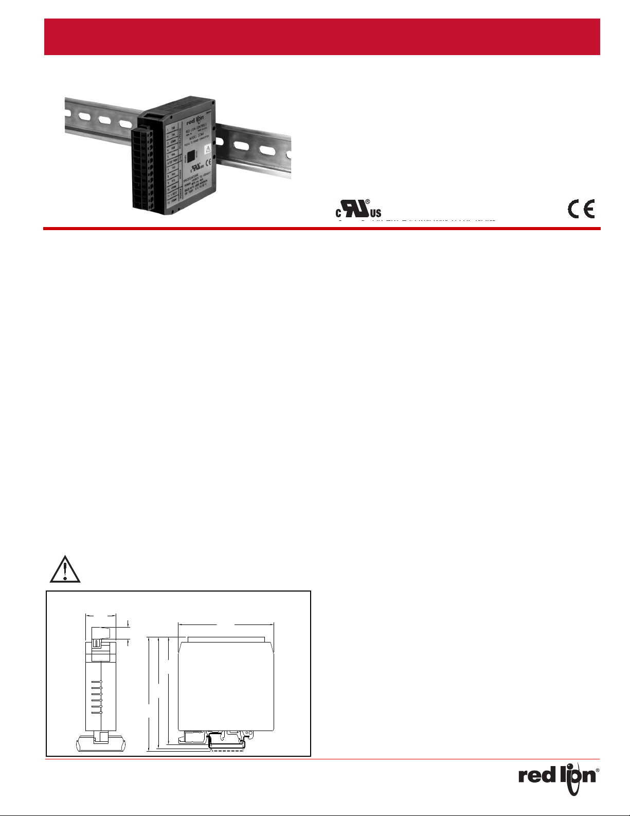
.98
(25)
.39
(10)
3.11
(79)
3.86
(98)
3.76
(95.5)
3.56
(90.5)
DIMENSIONSIninches(mm)
ModelICM4‐SerialCon verterModule(RS ‐232C/RS‐485)
• ALLOWS COMMUNICATIONS BETWEEN RS-232 CONTROL
EQUIPMENT AND PRODUCTS WITH RS-485 SERIAL
COMMUNICATIONS
• WIDE DC INPUT POWER RANGE (+9 to 32 VDC)
• HALF DUPLEX (RS-485) AND FULL DUPLEX (RS-422)
• LED INDICATION FOR RXD, TXD, and POWER
• UNIVERSAL MOUNTING FOOT FOR DIN RAIL INSTALLATION
Bulletin No. ICM4-F
Drawing No. LP0416
Released 2016-08-26
DESCRIPTION
The ICM4 Serial Converter Module provides the capability of
interfacing equipment with RS-485 serial communications to equipment
with RS-232 communications. Data format of the RS-232 and RS-485
equipment must be the same.
For full duplex (RS-422), the DIP switch on the side of the module
must be in the RS-422 position. For half duplex (RS-485), the DIP switch
must be in the RS-485 position. In half duplex mode, the RS-485 driver is
enabled using the leading edge of the first character transmitted (RXD
input). After the last character transmits, the converter waits one
character time (at 9600 baud) to disable the RS-485 driver.
There are 3 LED’s that can be viewed from the front of the converter
module. A green power LED indicates power is on, a red RS-232 TXD
LED flashes when the module is transmitting, and a green RS-232 RXD
LED flashes when the module is receiving.
An external DC power source (+9 to 32 VDC) is required to power the
ICM4. The external power source and serial communications
connections are made via a 12 position removable terminal block located
on the front of the module.
The unit is equipped with a universal mounting foot for attachment to
standard DIN style mounting rails, including top hat profile rail according
to EN50022 - 35 x 7.5 and 35 x 15, and G profile rail according to
EN50035 - G32.
SAFETYSUMMARY
All safety related regulations, local codes and instructions that appear
in this literature or on equipment must be observed to ensure personal
safety and to prevent damage to either the instrument or equipment
connected to it. If equipment is used in a manner not specified by the
manufacturer, the protection provided by the equipment may be
impaired.
DIMENSIONSIninches(mm)
SPECIFICATIONS
1. POWER: +9 to 32 VDC @ 75 mA maximum. Above 26 VDC, derate
max. operating temperature to 40 °C. Power supply must be Class 2
or SELV rated.
2. RS232 VOLTAGES:
Receive Data Pin: ± 30 VDC max.
Mark Condition: ≤ 0.8 VDC
Space Condition: ≥ 2.4 VDC
Transmit Data Pin:
Mark Condition: -8 VDC (typ.)
Space Condition: +8 VDC (typ.)
3. RS485 VOLTAGES:
Differential Output Voltage: ± 5 VDC max. under no load
Differential Input Voltage: ± 5 VDC max.
Mark Condition: ≤ -0.2 VDC
Space Condition: ≥ +0.2 VDC
RS485 Drive Capability: Up to 32 RS-485 receivers connected in
parallel.
RS485 Drive Disable Time: 4 msec. max.
4. MAXIMUM CABLE LENGTH:
RS232: 50 feet
RS485: 4000 feet
5. BAUD RATE: 9600 min., 19200 max.
6. CERTIFICATIONS AND COMPLIANCES:
CE Approved
EN 61326-1 Immunity to Industrial Locations
Emission CISPR 11 Class B
Safety requirements for electrical equipment for measurement,
control, and laboratory use:
EN 61010-1: General Requirements
RoHS Compliant
UL Recognized Component: File #E179259
IP20 Enclosure rating (Rear of unit)
Refer to EMC Installation Guidelines section of the bulletin for additional
information.
7. ENVIRONMENTAL CONDITIONS:
Operating Temperature Range: 0 to 50 °C. Derate max. operating
temperature to 40 °C above 26 VDC.
Storage Temperature: -40 to + 75 °C
Operating and Storage Humidity: 85% max.relative humidity
(non-condensing) from 0 to 50 °C
Vibration to IEC 68-2-6: Operational 5 to 150 Hz, 2 g.
Shock to IEC 68-2-27: Operational 30 g.
Altitude: Up to 2000 meters
8. CONSTRUCTION: Case body is black, high impact plastic. Installation
Category I, Pollution Degree 2.
9. MOUNTING: Standard DIN rail top hat (T) profile rail according to
EN50022- 35 X 7.5 and 35 X 15
10.WEIGHT: 3.2 oz. (90.7 g)
-1-
Released 2016-08-26 Bulletin No. ICM4-F
RS422
RS485
ON
RS485/RS422
SPECIFICATIONS
BAUD RATE: 9600 MINIMUM
OP. TEMP: 0° C TO 50° C
RED LION CONTROLS
MODEL ICM4
RS232 TO RS485 CONVERTER
YORK, PA.
COMM
COMM
+ DC
11
12
10
98RTS
RXD
POWER RS232
POWER:
COMM
TEST POINT
7 TXD
6
5 RXA
3
4 RXB
2 TXA
+5V
+9VDC TO +32VDC
@75 ma. MAX.
MADE IN U.S.A.
!
1 TXB
M2293C
TX
RX
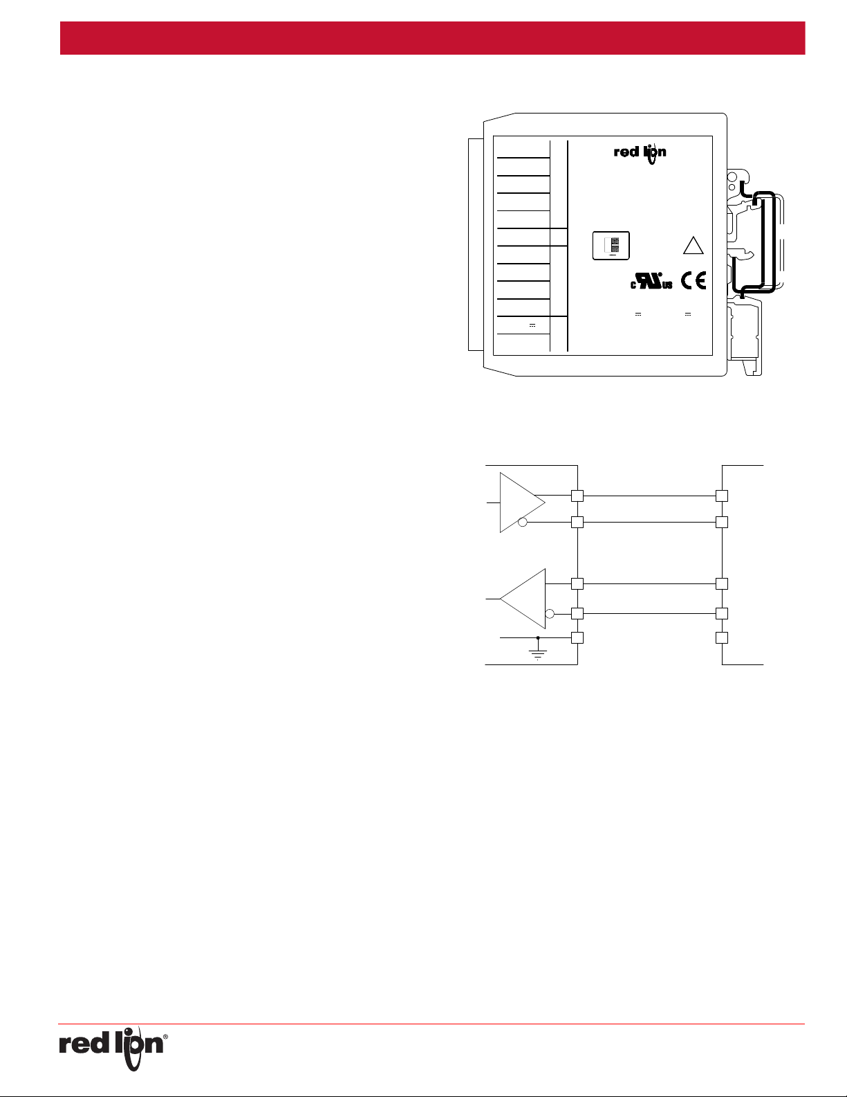
2
TRANSMIT DATA
TRANSMIT DATA RETURN
RECEIVE DATA
RECEIVE DATA RETURN
SIGNAL COMMON
1
5
4
3
*
*
*
*
*
RX+
RX-
TX+
TX-
ICM4
CONNECTING
DEVICE
B"
"
A"
"
B"
"
A"
"
Drawing No. LP0416
EMCINSTALLATIONGUIDELINES
Although Red Lion Controls products are designed with a high degree
of immunity to Electromagnetic Interference (EMI), proper installation and
wiring methods must be followed to ensure compatibility in each
application. The type of the electrical noise, source or coupling method
into a unit may be different for various installations. Cable length, routing,
and shield termination are very important and can mean the difference
between a successful or troublesome installation. Listed are some EMI
guidelines for a successful installation in an industrial environment.
1. A unit should be mounted in a metal enclosure, which is properly
connected to protective earth.
2. Use shielded cables for all Signal and Control inputs. The shield
connection should be made as short as possible. The connection point
for the shield depends somewhat upon the application. Listed below
are the recommended methods of connecting the shield, in order of
their effectiveness.
a. Connect the shield to earth ground (protective earth) at one end
where the unit is mounted.
b. Connect the shield to earth ground at both ends of the cable, usually
when the noise source frequency is over 1 MHz.
3. Never run Signal or Control cables in the same conduit or raceway with
AC power lines, conductors, feeding motors, solenoids, SCR controls,
and heaters, etc. The cables should be run through metal conduit that
is properly grounded. This is especially useful in applications where
cable runs are long and portable two-way radios are used in close
proximity or if the installation is near a commercial radio transmitter.
Also, Signal or Control cables within an enclosure should be routed as
far away as possible from contactors, control relays, transformers, and
other noisy components.
4. Long cable runs are more susceptible to EMI pickup than short cable
runs.
5. In extremely high EMI environments, the use of external EMI
suppression devices such as Ferrite Suppression Cores for signal and
control cables is effective. The following EMI suppression devices (or
equivalent) are recommended:
Fair-Rite part number 0443167251 (Red Lion Controls # FCOR0000)
Line Filters for input power cables:
Schaffner # FN2010-1/07 (Red Lion Controls # LFIL0000)
6. To protect relay contacts that control inductive loads and to minimize
radiated and conducted noise (EMI), some type of contact protection
network is normally installed across the load, the contacts or both. The
most effective location is across the load.
a. Using a snubber, which is a resistor-capacitor (RC) network or metal
oxide varistor (MOV) across an AC inductive load is very effective at
reducing EMI and increasing relay contact life.
b. If a DC inductive load (such as a DC relay coil) is controlled by a
transistor switch, care must be taken not to exceed the breakdown
voltage of the transistor when the load is switched. One of the most
effective ways is to place a diode across the inductive load. Most
Red Lion products with solid state outputs have internal zener diode
protection. However external diode protection at the load is always a
good design practice to limit EMI. Although the use of a snubber or
varistor could be used.
Red Lion part numbers: Snubber: SNUB0000
7. Care should be taken when connecting input and output devices to the
instrument. When a separate input and output common is provided,
they should not be mixed. Therefore a sensor common should NOT be
connected to an output common. This would cause EMI on the
sensitive input common, which could affect the instrument’s operation.
Visit www.redlion.net/emi for more information on EMI guidelines,
Safety and CE issues as they relate to Red Lion products.
Varistor: ILS11500 or ILS23000
SIDE VIEW OF ICM4
TYPICAL RS-422 CONNECTIONS
Notes:
1. Connect shield drain wire to earth ground.
2. Place DIP switch on the side of the ICM4 in the 422 position.
3. RS-422 polarity: Terminal “A” is negative with respect to Terminal “B” in
the mark (logic 1) condition.
-2-

Released 2016-08-26 Bulletin No. ICM4-F
TX
RX
TWO WIRE
RS-485 BUS
REFERENCE GROUND
A"
B"
A"
B"
ȍ
"
"
"
"
1
5
4
3
2 *
*
*
TX/RX+
TX/RX-
ICM4 CONNECTING DEVICE
TX
RX
TWO WIRE
RS-485 BUS
REFERENCE GROUND
A"
B"
A"
B"
ȍ
"
"
"
"
1
5
4
3
2
*
*
*
TX/RX+
TX/RX-
ICM4
CONNECTING DEVICE
TWO WIRE
RS-485 BUS
*
*
TX/RX+
TX/RX-
CONNECTING DEVICE
8
7
10
7
3
2
RECEIVE DATA
TRANSMIT DATA
SIGNAL COMMON SIGNAL COMMON
TRANSMIT DATA
RECEIVE DATA
ICM4 RS232 DEVICE (25 pin)
ICM4 connector pin #'s
ICM4 connector pin #'s
RS232 DEVICE (9 pin)ICM4
RECEIVE DATA
TRANSMIT DATA
SIGNAL COMMONSIGNAL COMMON
TRANSMIT DATA
RECEIVE DATA
2
3
5
10
7
8
Drawing No. LP0416
TYPICAL RS-485 CONNECTIONS
TYPICAL MULTIPLE RS-485 CONNECTIONS
TYPICAL RS-232 CONNECTIONS
Notes:
1. Connect shield drain wire to earth ground.
2. Place DIP switch on the side of the ICM4 in the 485 position.
3. The transmit and receive data lines of the ICM4 should be wired
together.
-3-

Released 2016-08-26 Bulletin No. ICM4-F
LIMITED WARRANTY
(a) Red Lion Controls Inc., Sixnet Inc., N-Tron Corporation, or Blue Tree Wireless Data, Inc. (the “Company”)
warrants that all Products shall be free from defects in material and workmanship under normal use for the period of
time provided in “Statement of Warranty Periods” (available at www.redlion.net) current at the time of shipment of the
Products (the “Warranty Period”). EXCEPT FOR THE ABOVE-STATED WARRANTY, COMPANY MAKES NO
WARRANTY WHATSOEVER WITH RESPECT TO THE PRODUCTS, INCLUDING ANY (A) WARRANTY OF
MERCHANTABILITY; (B) WARRANTY OF FITNESS FOR A PARTICULAR PURPOSE; OR (C) WARRANTY
AGAINST INFRINGEMENT OF INTELLECTUAL PROPERTY RIGHTS OF A THIRD PARTY; WHETHER EXPRESS
OR IMPLIED BY LAW, COURSE OF DEALING, COURSE OF PERFORMANCE, USAGE OF TRADE OR
OTHERWISE. Customer shall be responsible for determining that a Product is suitable for Customer’s use and that
such use complies with any applicable local, state or federal law.
(b) The Company shall not be liable for a breach of the warranty set forth in paragraph (a) if (i) the defect is a result
of Customer’s failure to store, install, commission or maintain the Product according to specifications; (ii) Customer
alters or repairs such Product without the prior written consent of Company.
(c) Subject to paragraph (b), with respect to any such Product during the Warranty Period, Company shall, in its
sole discretion, either (i) repair or replace the Product; or (ii) credit or refund the price of Product provided that, if
Company so requests, Customer shall, at Company’s expense, return such Product to Company.
(d) THE REMEDIES SET FORTH IN PARAGRAPH (c) SHALL BE THE CUSTOMER’S SOLE AND EXCLUSIVE
REMEDY AND COMPANY’S ENTIRE LIABILITY FOR ANY BREACH OF THE LIMITED WARRANTY SET FORTH
IN PARAGRAPH (a).
Drawing No. LP0416
INSTALLATION
The unit is equipped with a universal mounting foot for attachment to standard DIN style mounting rails, including G profile rail according to EN50035
- G32 , and top hat (T) profile rail according to EN50022 - 35 x 7.5 and 35 x 15. The unit should be installed in a location that does not exceed the
maximum operating temperature and provides good air circulation. Placing the unit near devices that generate excessive heat should be avoided.
G Rail Installation
To install the ICM4 on a “G” style DIN rail, angle the module so that
the upper groove of the “foot” catches under the lip of the top rail. Push
the module toward the rail until it snaps into place. To remove a module
from the rail, push up on the bottom of the module while pulling out away
from the rail.
To install the ICM4 on a “T” style rail, angle the module so that the top
groove of the “foot” is located over the lip of the top rail. Push the module
toward the rail until it snaps into place. To remove a module from the rail,
insert a screwdriver into the slot on the bottom of the “foot”, and pry
upwards on the module until it releases from the rail.
T Rail Installation
ORDERINGINFORMATION
MODEL NO. DESCRIPTION PART NUMBER
ICM4 RS-232/RS-485 Converter Module ICM40030
-4-
 Loading...