

Page 1
MODEL IAMA - CONFIGURABLE 3-WAY ISOLATING AMPLIFIER
C
US
3-WAY ISOLATION OF ANALOG SIGNALS
UNIVERSAL CONVERSION MODULE - INPUTS AND OUTPUTS
SELECTED VIA DIP SWITCH SETTINGS
OVER 35 INPUT AND OUTPUT ANALOG CONVERSION
COMBINATIONS
ULTRA SLIM DESIGN – ONLY 0.244" WIDE
19 to 30 VDC POWER
PROCESS CONTROL
U
C
LISTED
R
L
EQUIPMENT FOR HAZARDOUS
US
LOCATIONS 31ZN
CLASS 1, DIV 2
GROUPS A, B, C, D T5
GENERAL DESCRIPTION
The IAMA can isolate and convert over 35 combinations of analog signal
ranges. The IAMA converts and transmits signals linearly proportional to the
input. DIP switch range selection eliminates the need to order and stock
different modules for each input and output signal range, and allows quick and
convenient setup for over 35 standard signal conversions. In addition to the
SAFETY SUMMARY
All safety related regulations, local codes and instructions that appear in the
manual or on equipment must be observed to ensure personal safety and to
prevent damage to either the instrument or equipment connected to it. If
equipment is used in a manner not specified by the manufacturer, the protection
provided by the equipment may be impaired.
conversion capabilities, the IAMA modules feature optically isolated Input/
Output signal circuits and isolated Power to Input, Power to Output circuits. The
modules’ overall full scale accuracy typically exceed 0.04%. DIN rail mounting
saves time and panel space. The units are equipped with universal mounting feet
for attachment to standard top hat profile rail according to EN50022 - 35x7.5.
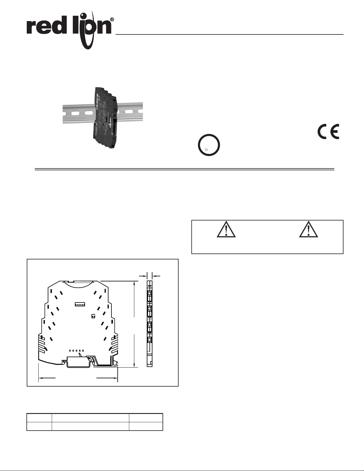
DIMENSIONS In inches (mm)
0.24
(6.2)
1
5
on
S2
off
6
6
1
1 2
7
8
1
2
on
off
2
S1
4.00
3
(101.6)
3
4
4
CAUTION: Read complete
instructions prior to installation
and operation of the unit.
SPECIFICATIONS
1. POWER: 19.2 to 30 V DC, 450 mW max.
2. INPUT / OUTPUT RANGES: See table 1
3. SPAN ADJUSTMENT: Potentiometer, located below transparent top cover.
4. MAX INPUT SIGNAL:
Current: 50 mA
Voltage: 30 V
5. INPUT RESISTANCE:
Current: Approx. 50
Voltage: Approx. 100 k
6. OUTPUT: Self-powered (Active)
7. MAX OUTPUT SIGNAL:
Current: 28 mA/12.5 V
CAUTION: Risk of electric shock.
Voltage: 12.5 V/22 mA
8. LOAD RESISTANCE:
Current: 500 max.
Voltage: 10 k min
9. OUTPUT COMPLIANCE:
Current: 12.5 V max (500 ). Ripple: < 20 mV
3.65 (92.7)
Voltage: 22 mA (10 k). Ripple: < 20 mV
10. TRANSMISSION ERROR:
The transmission error without adjustment is < 0.4%. Using the potentiometer,
the error can be adjusted to < 0.1%.
11. TEMPERATURE COEFFICIENT:
ORDERING INFORMATION
MODEL NO. DESCRIPTION PART NUMBER
IAMA IAMA0006Configurable 3-Way Isolating Amplifier
Max.: < 0.01%/K
Typ.: < 0.002%/K
12. CUT-OFF FREQUENCY: 100 Hz
13. STEP RESPONSE (FROM 10 to 90 %): 3.5 msec
14. TEST VOLTAGE (Input/Output/Supply): 1.5 kV, 50 Hz, 1 min.
15. ENVIRONMENTAL CONDITIONS:
Operating Temperature Range: -20°C to 65°C (-4°F to 149°F)
Storage Temperature Range: -40°C to +85°C (-40°F to 185°F)
1
Page 2
16. TESTS/APPROVALS:
C
US
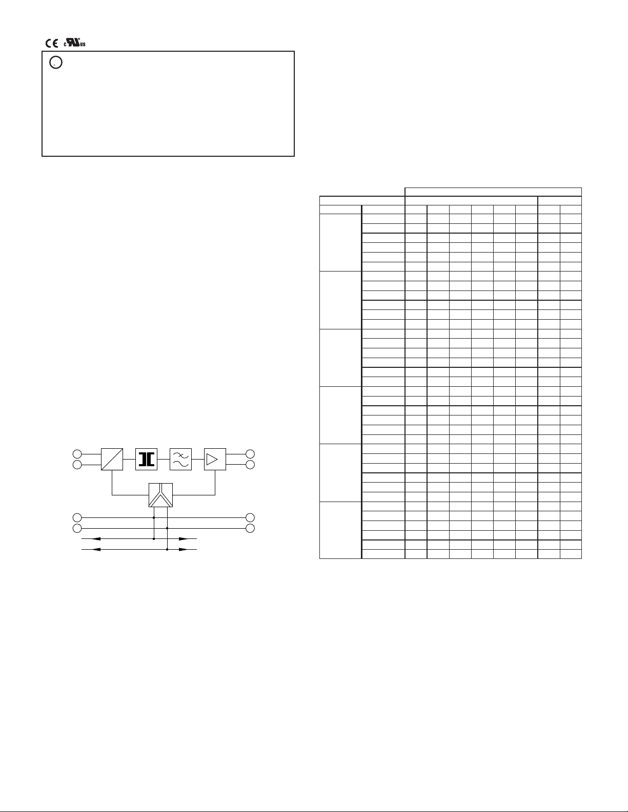
I,U
1
2
IN UI
GND1
5
6
OUT UI
GND2
U
U,I
DCDCDC
4
3
GND3
UB + UB +
8
7
GND3
PROCESS CONTROL EQUIPMENT FOR
U
R
C
US
L
HAZARDOUS LOCATIONS
LISTED
31ZN
Class I Div 2 Groups A, B, C, D T5
A) This equipment is suitable for use in Class I, Division 2, Groups A, B,
C and D or non- hazardous locations only.
B) Warning - explosion hazard - substitution of components may impair
suitability for Class 1, Division 2.
C) W arning - explosion hazard - do not disconnect equipment unless power
has been switched off or the area is known to be non-hazardous.
INPUTS
The IAMA accepts a full range of process signal inputs and isolates and
converts these signals to common industrial control signals. The input signal
combinations are configured by making specific DIP switch selections on the 6
and 2 position DIP switches.
OUTPUTS
As with the input choices, the process signal output of the modules is DIP
switch selectable. The maximum output current signal is 28 mA with =500
output resistance and the maximum output voltage signal is 12.5 V with =10 K
output resistance. The transmission error without adjustment is < 0.4%. Using
the potentiometer, the error can be adjusted to < 0.1%.
17. CERTIFICA TIONS AND COMPLIANCES:
Conformance With EMC Guideline 2004/108/EC And Low Voltage Directive 2006/95/EC
Immunity to Interference According to EN 61000-6-2
Discharge of static electricity (ESD) EN 61000-4-2 Criterion B
Electromagnetic HF field EN 61000-4-3 Criterion A
Fast transients (Burst) EN 61000-4-4 Criterion B
Surge voltage capacities (Surge) EN 61000-4-5 Criterion B
Conducted disturbance EN 61000-4-6 Criterion A
Noise Emission According to EN 50081-2
Noise emission of housing EN 55011
1
EN 61000 corresponds to IEC 1000
2
Criterion B: T emporary impairment to operational behavior that is corrected
by the device itself.
3
Criterion A: Normal operating behavior within the defined limits.
4
EN 55011 corresponds to CISPR11
5
Class A: Area of application industry.
1
2
3
2
2
3
4
Class A
5
18. CONNECTIONS: 12 AWG max., Stripping length: 0.47" (12 mm)
19. CONSTRUCTION: Polybutylenterephthalate PBT, black
20. MOUNTING: Standard DIN top hat (T) profile rail according to EN50022
- 35x7.5
21. WEIGHT: 2 oz. (54 g)
BLOCK DIAGRAM
TABLE 1 - CONFIGURATION
RANGES
IN
0 –10 V
2 – 10 V
0 – 5 V
1 – 5 V
0 – 20 mA
4 - 20 mA
OUT 1
0 – 20 mA off off off off off off off off
4 - 20 mA off off off off off ON off off
0 – 10 V ON off ON off off off off off
2 – 10 V ON off ON off off ON off off
0 – 5 V ON ON off off off off off off
1 – 5 V ON ON off off off ON off off
0 – 20 mA off off off ON ON off off off
4 - 20 mA off off off off off off off off
0 – 10 V ON off ON ON ON off off off
2 – 10 V ON off ON off off off off off
0 – 5 V ON ON off ON ON off off off
1 – 5 V ON ON off off off off off off
0 – 20 mA off off off off off off ON off
4 - 20 mA off off off off off ON ON off
0 – 10 V ON off ON off off off ON off
2 – 10 V ON off ON off off ON ON off
0 – 5 V ON ON off off off off ON off
1 – 5 V ON ON off off off ON ON off
0 – 20 mA off off off ON ON off ON off
4 - 20 mA off off off off off off ON off
0 – 10 V ON off ON ON ON off ON off
2 – 10 V ON off ON off off off ON off
0 – 5 V ON ON off ON ON off ON off
1 – 5 V ON ON off off off off ON off
0 – 20 mA off off off off off off off ON
4 - 20 mA off off off off off ON off ON
0 – 10 V ON off ON off off off off ON
2 – 10 V ON off ON off off ON off ON
0 – 5 V ON ON off off off off off ON
1 – 5 V ON ON off off off ON off ON
0 – 20 mA off off off ON ON off off ON
4 - 20 mA off off off off off off off ON
0 – 10 V ON off ON ON ON off off ON
2 – 10 V ON off ON off off off off ON
0 – 5 V ON ON off ON ON off off ON
1 – 5 V ON ON off off off off off ON
DIP SWITCHES
OUTPUT (S2)
2 3 4 5 6 1
INPUT (S1)
2
2
Page 3

WIRING CONNECTIONS
5
6
7
8
-
+
RECORDER
CHART
FLOW
SENSOR
0-5 VDC
IAMA6
Primary power is connected to terminals 7 or 3 (19.2 – 30 VDC) and 8 or 4
(GND 3). For best results, the power should be relatively “clean” and within the
specified variation limits. Drawing power from heavily loaded circuits or from
circuits that also power loads that cycle on and off, should be avoided.
The input signal is connected to pins 1 (In U,I) and 2 (GND 1). Connections
for the output signal are made on pins 5 (Out U,I) and 6 (GND 2).
OUT UI 5
GND2 6
19.2...30VDC 7
GND3 8
on
S2
off
6
1
1 2
DIN rail release latch
1 IN UI
2 GND1
on
S1
off
3 19.2...30VDC
4 GND3
INSTALLATION
The unit is equipped with a universal mounting foot for attachment to
standard DIN style top hat (T) profile rail according to EN50022 - 35 x 7.5 and
35 x 15. The unit should be installed in a location that does not exceed the
maximum operating temperature and provides good air circulation. Placing the
unit near devices that generate excessive heat should be avoided.
T Rail Installation
To install the IAMA on a “T”
style rail, angle the module so that
the top groove of the “foot” is
located over the lip of the top rail.
Push the module toward the rail
until it snaps into place. To
remove a module from the rail,
insert a screwdriver into the slot
on the bottom of the “foot”, and
pry upwards on the module until it
releases from the rail.
APPLICATION
Cost efficiency measurements of a printing company included the reduction
of bulk stock of the various inks used in their printing processes. The
company currently had various ink flow and level devices with different
current and voltage outputs and wanted to record these measurements into a
control room PC. Several IAMA Universal Signal Conditioning Modules
were the answer. The IAMA’s universal input allowed for easy signal
conditioning of the various output signals to the required PC’s Bus Board
0 to 10 VDC input signal. In this case, the IAMA’s re-transmitted 0 to 10
VDC output was field calibrated, negating the expense and time
required to rewrite the PC’s software parameters. In addition to
accepting multiple signal types, the IAMA also provides the
necessary electrical isolation between the control room PC
and the hazards of the printing floor electrical noise.
3
 Loading...