

Page 1
Bulletin No. GRAPH-H
CAUTION: Risk Of Danger.
Read complete instructions prior to
installation and operation of the unit.
CAUTION: Risk of electric shock.
WARNING - EXPLOSION HAZARD - DO NOT DISCONNECT
EQUIPMENT UNLESS POWER HAS BEEN SWITCHED OFF
OR AREA IS KNOWN TO BE NON-HAZARDOUS.
WARNING - EXPLOSION HAZARD - DO NOT DISCONNECT
EQUIPMENT UNLESS POWER HAS BEEN SWITCHED OFF
OR AREA IS KNOWN TO BE NON-HAZARDOUS.
WARNING - EXPLOSION HAZARD - SUBSTITUTION OF
COMPONENTS MAY IMPAIR SUITABILITY FOR CLASS I,
DIVISION 2.
FOR USE IN HAZARDOUS LOCATIONS:
Class I, Division 2, Groups A, B, C, and D
Class II, Division 2, Groups F and G
Class III, Division 2
C
US
U
L
R
LISTED
IND.CONT. EQ.
3PWL
II 3 G Ex ic nA IIC T4 Gc
II 3 D Ex tc IIIC T135°C Dc
DEMKO 14 ATEX 1387X
IECEx UL 15.0035X
C
US LISTED
U
L
R
IND. CONT
. EQ.
34AD
Drawing No. LP0918
Released 2015-11-23
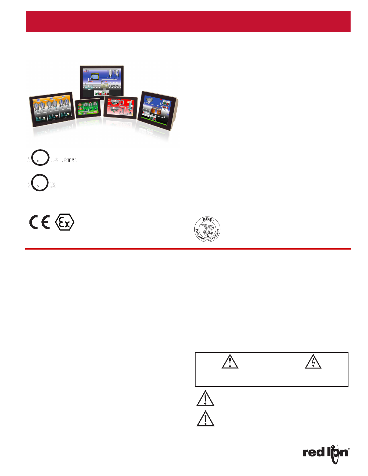
GRAPHITE® SERIES - OPERATOR INTERFACE TERMINALS WITH PLUG-IN I/O
MODULE CAPABILITY
• PROTOCOL CONVERSION FEATURE CONVERTS NUMEROUS
PROTOCOLS SIMULTANEOUSLY
• OVER 250 BUILT-IN DRIVERS ALLOWS EASY DATA MAPPING
TO PLCS, PCS, AND SCADA SYSTEMS
• BUILT-IN WEB SERVER ALLOWS REMOTE VIEW OR CONTROL
FROM ANY INTERNET CONNECTED PC OR SMART PHONE
• SYNCS DATA LOGS TO FTP SERVERS AND MICROSOFT SQL
SERVER
• PROVIDES EMAIL AND SMS TEXT MESSAGE ALERTS (Requires
GMHSPA module)
• CONFIGURED USING CRIMSON
• UP TO 4 FULLY ISOLATED SERIAL COMMUNICATION PORTS,
(2 RS-232 and 1 RS-422/485)
• 10 BASE T/100 BASE-TX ETHERNET CONNECTION CAN
CONNECT TO AN UNLIMITED NUMBER OF DEVICES VIA TEN
PROTOCOLS SIMULTANEOUSLY
• EASY TO ADD I/O CAPABILITY WITH GRAPHITE PLUG-IN
MODULES
• ALUMINUM CASE CONSTRUCTION FOR BOTH THE OPERATOR
INTERFACE TERMINAL AND THE I/O MODULES
®
®
3 SOFTWARE
GENERAL DESCRIPTION
The Graphite® Series merges two of our most highly successful
product platforms into a single, extremely flexible solution. The nexus of
the product is the operator interface panel which offers the award
winning technology of our G3 HMI Series including protocol conversion,
data logging and remote access. Programming the unit is easy using
drag and drop selection within our Crimson 3 software allowing complete
set-up in minutes. Add to all that capability, plug-in modules which
provide I/O functions within the framework of the operator interface
panel. The I/O modules are similar to our Modular Controller Series
product providing easy interface of sensors, discreet outputs and
communication modules. The result is a complete industrial solution that
connects, monitors, and controls while providing real time displays.
The operator interface panels are available in 5 different panel sizes;
7", 9", 10", 12" and 15", with the 7", 9" and 12" displays in the wide
screen format. The displays are full color touch panels in VGA, SVGA or
XGA formats and operate as full touchscreens. The all-aluminum
construction provides very robust packaging that can withstand even the
most demanding environments. If your application calls for outdoor use,
we have two models, 7" and 10" that are designed for just that
requirement.
The units are able to communicate with many types of hardware
simultaneously using high-speed RS-232/485 communication ports and
Ethernet 10 Base T/100 Base-TX communications. Currently over 250
drivers are selectable in the Crimson Software which allows easy data
mapping to PLCs, PCs, and SCADA Systems. In addition, the Graphite
Series features USB host capability for fast downloads of configuration
files and access to trending and data logging information.
CONTENTS OF PACKAGE
- Operator Interface
- Hardware packet for mounting unit into panel
- Terminal block for connecting power
- Panel gasket
SAFETY SUMMARY
All safety related regulations, local codes and instructions that appear
in the manual or on equipment must be observed to ensure personal
safety and to prevent damage to either the instrument or equipment
connected to it. If equipment is used in a manner not specified by the
manufacturer, the protection provided by the equipment may be
impaired.
Do not use the controller to directly command motors, valves, or other
actuators not equipped with safeguards. To do so can be potentially
harmful to persons or equipment in the event of a fault to the unit.
-1-
Page 2
Released 2015-11-23 Bulletin No. GRAPH-H
WARNING - DO NOT CONNECT OR DISCONNECT CABLES
WHILE POWER IS APPLIED UNLESS AREA IS KNOWN TO BE
NON-HAZARDOUS.
Drawing No. LP0918
SPECIFICATIONS
1. POWER REQUIREMENTS:
Must use a Class 2 circuit according to National Electrical Code (NEC),
NFPA-70 or Canadian Electrical Code (CEC), Part I, C22.1 or a
Limited Power Supply (LPS) according to IEC 60950-1 or Limitedenergy circuit according to IEC 61010-1.
Power connection via removable three position terminal block.
See Table below for power ratings
2. BATTERY: Lithium coin cell. Typical lifetime of 6 years, nominal.
3. LCD DISPLAY: See Table below for detailed display specifications.
4. TOUCHSCREEN: Resistive analog
5. MEMORY:
On Board User Memory: 256 Mbyte of non-volatile Flash memory.
Memory Card: SD slot accepts standard capacity cards up to 2Gbyte.
6. COMMUNICATION CAPABILITIES:
USB Device Port: Adheres to USB specification 2.0 (high speed, full
speed) only using Type B connection.
SYSTEM SET-UP AND DIAGNOSTICS AND IS NOT INTENDED FOR
PERMANENT CONNECTION.
USB DEVICE PORT IS FOR
USB Host Ports: Comply with Universal Serial Bus Specification Rev
2.0. Support data transfers at (high speed, full speed). Hardware
over current protected (0.5 A max per port).
Serial Ports: Ports are individually isolated. Format and Baud Rates for
each port are individually software programmable up to 115,200
baud.
PGM Port: RS232 port via RJ12.
COMMS Ports: RS422/485 port via RJ45, and RS232 port via RJ12.
DH485 TXEN: Transmit enable; open collector, V
= 0.5 V @ 25 mA max.
V
OL
= 15 VDC,
OH
Port to Port Isolation: 1000 Vrms (G07: 500 Vrms) for 1 minute.
Signal Isolation: 50 V.
Ethernet Port: 10 BASE-T / 100 BASE-TX
RJ45 jack is wired as a NIC (Network Interface Card).
Isolation from Ethernet network to Graphite operator interface: 1500
Vrms
7. ENVIRONMENTAL CONDITIONS:
Operating Temperature Range: -20 to 60 °C
Storage Temperature Range: -20 to 70 °C
Vibration to IEC 68-2-6: Operational 5-500 Hz, 4 g
Shock to IEC 68-2-27: Operational 40 g (10 g, modules w/relays)
Operating and Storage Humidity: 0 to 85% max. RH non-condensing
Altitude: Up to 2000 meters
8. CERTIFICATIONS AND COMPLIANCES:
CE Approved
EN 61326-1 Immunity to Industrial Locations
Emission CISPR 11 Class A
IEC/EN 61010-1
RoHS Compliant
ATEX Approved
II 3 G Ex ic nA IIC T4 Gc
II 3 D Ex tc IIIC T135°C Dc
DEMKO 14 ATEX 1387X
EN 60079-0, -11, -15, -31
IECEx Approved
Ex ic nA IIC T4 Gc
Ex tc IIIC T135°C Dc
IECEx UL 15.0035X
IEC 60079-0, -11, -15, -31
UL Listed: File #E302106
UL Hazardous: File #E317425
Type 4X Indoor / IP66 Enclosure rating (Face only) for all models
Type 4X Outdoor Enclosure rating (Face only) for GxxSxxxx models
ABS Type Approval for Shipboard Applications
9. CONNECTIONS: High compression cage-clamp terminal block
Wire Strip Length: 0.3" (7.5 mm)
Wire Gauge Capacity: One 14 AWG (1.63 mm) solid,
two 18 AWG (1.02 mm) or four 20 AWG (0.81 mm)
10.CONSTRUCTION: Cast aluminum enclosure with NEMA 4X/IP66
rating for indoor use only when correctly fitted with the gasket provided.
Installation Category II, Pollution Degree 2 as defined in IEC 60664-1.
These devices have only been evaluated for low risk of mechanical
impact.
11.MOUNTING REQUIREMENTS: Maximum panel thickness is 0.188"
(4.78 mm) with removable foot, or 0.375" (9.53 mm) without foot. For
NEMA 4X/IP66 sealing, a steel panel with a minimum thickness of
0.125" (3.17 mm) is recommended.
Maximum Mounting Screw Torque: 6.0 lbf inch (96 ozf inch) (0.68 Nm)
12.WEIGHT:
G07: 2.26 lb. (1.03 Kg)
G09: 3.39 lb. (1.54 Kg)
G10: 4.8 lb. (2.18 Kg)
G12: 5.06 lb. (2.29 Kg)
G15: 7.73 lb. (3.5 Kg)
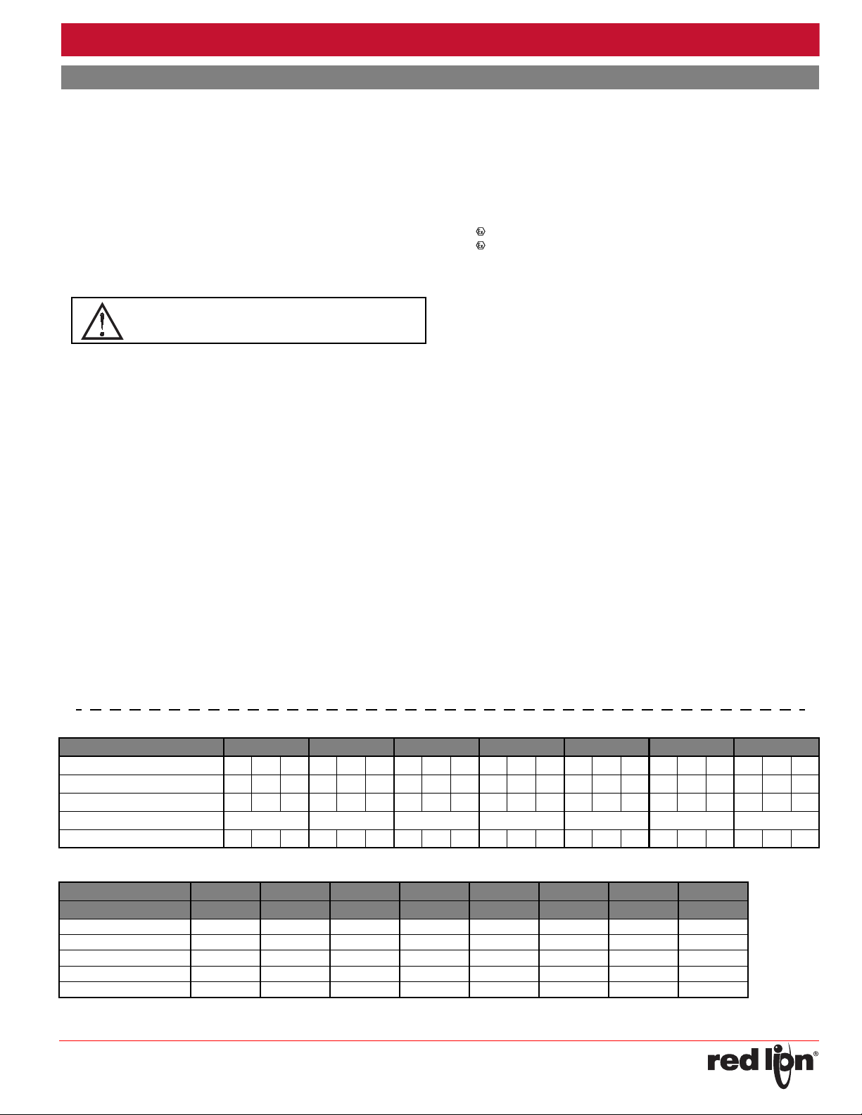
POWER:
MODEL G07C G07S G09 G10C/R G10S G12 G15
Input Voltage 10V 24V 30V 10V 24V 30V 10V 24V 30V 10V 24V 30V 10V 24V 30V 10V 24V 30V 10V 24V 30V
Typical Power HMI only: 7 W 7 W 8 W 8 W 9 W 9 W 11 W 12 W 12 W 10 W 11 W 11 W 15 W 16 W 16 W 13 W 14 W 15 W 18 W 18W 18 W
Maximum Power HMI only: 12 W 13 W 14 W 13 W 14 W 15 W 16 W 17 W 18 W 15 W 16 W 17 W 20 W 21 W 22 W 19 W 20 W 20 W 23 W 24 W 24 W
Available Power for Modules: 21 W 21 W 25 W 29 W 29 W 33 W 33 W
Max Power HMI With Module(s): 33 W 34 W 35 W 34 W 36 W 36 W 41 W 43 W 43 W 44 W 46 W 47 W 50 W 51 W 52 W 52 W 54 W 55 W 56 W 58W 58 W
LCD DISPLAY:
MODEL G07C G07S G09 G10C G10R G10S G12 G15
SIZE 7 - INCH 7 - INCH 9 - INCH 10 - INCH 10 - INCH 10 - INCH 12 - INCH 15 - INCH
COLORS WVGA, 16 M WVGA, 16 M WVGA, 16 M VGA, 16 M SVGA, 16 M VGA, 16 M WXGA, 16 M XGA, 16 M
PIXELS 800 X 480 800 X 480 800 X 480 640 X 480 800 X 600 640 X 480 1280 X 800 1024 X 768
BRIGHTNESS
BACKLIGHT (HR TYP.) * 40,000 40,000 70,000 70,000 70,000 35,000 70,000 70,000
BACKLIGHT TYPE LED LED LED LED LED LED LED LED
* Lifetime at room temperature (25°C)
500 cd/m
2
1000 cd/m2400 cd/m
2
450 cd/m
-2-
2
400 cd/m22500 cd/m2400 cd/m
2
400 cd/m
2
Page 3
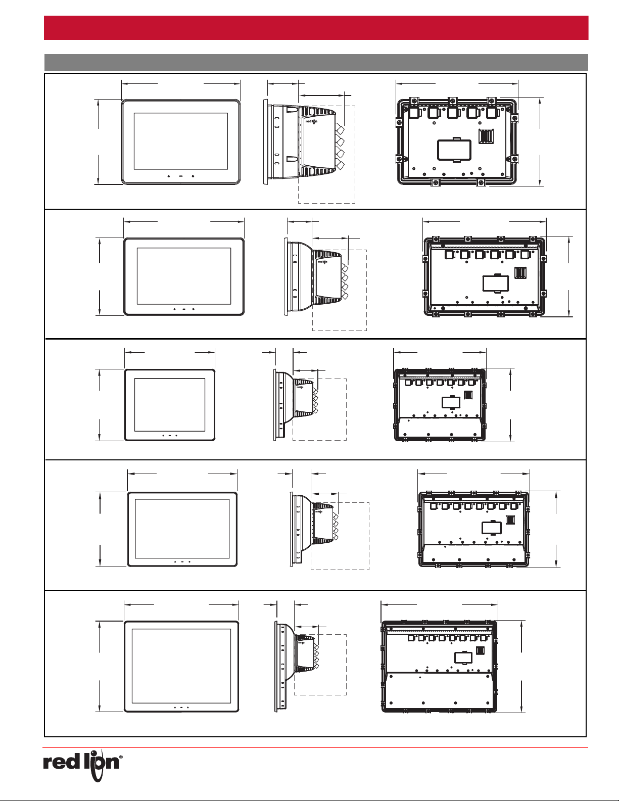
(MOUNTING CLIPS INSTALLED)
5.51
(139.9)
7.70 (195.5) 2.00 (50.8)
5.7
(146)
7.9 (202)
2.97 (76)
Module sold
separately
G07
2.06 (52.4)
10.06 (255.6)
6.47
(164.4)
6.7
(171)
(MOUNTING CLIPS INSTALLED)
10.3 (262)
2.97 (76)
Module sold
separately
10.84 (275.2)
8.57
(217.7)
2.06 (52.4)
8.8
(224)
(MOUNTING CLIPS INSTALLED)
11.1 (281)
2.97 (76)
Module sold
separately
12.10 (307.3)
8.20
(208.3)
2.06 (52.4)
8.4
(215)
(MOUNTING CLIPS INSTALLED)
12.3 (314)
2.97 (76)
Module sold
separately
11.10
(281.8)
14.03 (356.3)
2.14 (54.3)
11.3
(288)
(MOUNTING CLIPS INSTALLED)
14.3 (363)
2.97 (76)
Module sold
separately
G09
G10
G12
G15
Released 2015-11-23 Bulletin No. GRAPH-H
Drawing No. LP0918
DIMENSIONS IN inches (mm)
-3-
Page 4
Released 2015-11-23 Bulletin No. GRAPH-H
MOUNTING
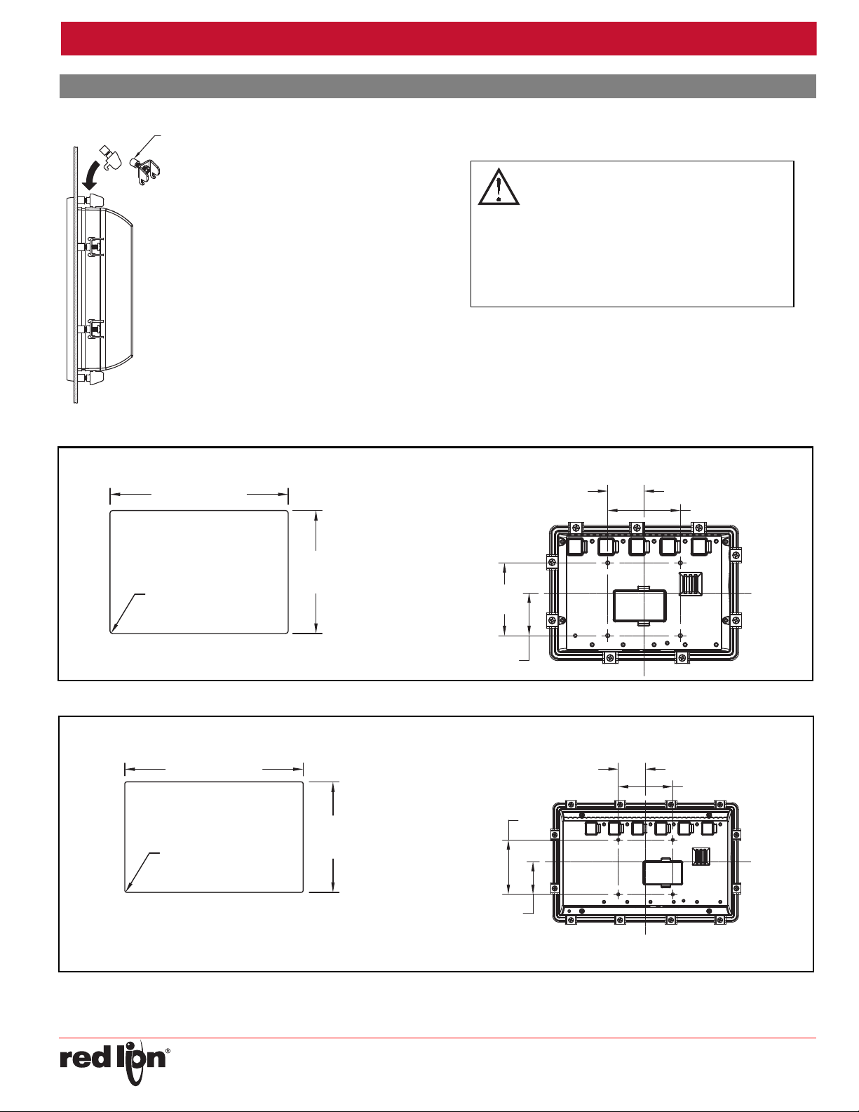
This operator interface is primarily designed for
through-panel mounting. Four VESA mount tapped
screw-holes (M4 x 0.7, 5 mm deep) are present on the
rear of the panels to allow for stand or wall mounting.
Care should be taken to remove any loose material from
the mounting cut-out to prevent that material from falling
into the operator interface during installation. A gasket is
provided to enable sealing to NEMA 4X/IP66
specification. Install the mounting clips provided and
tighten to 6.0 pound-force inch [96 ounce-force inch]
(0.68 N m) evenly for uniform gasket compression.
Provisions should be made to prohibit the product from
being exposed to UV radiation while in use. Care should
be taken not to rub or buff the touchscreen surface in a
way that might cause the accumulation of static charges.
FOOT MAY BE REMOVED
FOR THICKER PANEL
INSTALLATIONS
For hazardous location installation, this device must
be mounted in a suitable ATEX/IECEx certified endenclosure with a minimum ingress protection rating
of at least IP66 as defined in EN/IEC 60529 and
used in an environment of not more than Pollution Degree 2
per EN 60664-1. Must be wired using Division 2 wiring
methods as specified in article 501-4 (b), 502-4 (b), and 503-3
(b) of the National Electrical Code, NFPA 70 for installation
within the United States, or as specified in section 19-152 of
Canadian Electrical Code for installation in Canada.
G07
4.869
(123.7)
7.060 (179.3)
4X R.10 (2.5)
MAX.
All tolerances ±.059" (±1.5 mm)
2.95 (75)
2.95
(75)
1.73
(44)
PANEL CUT-OUT VESA MOUNT (MIS-D 75) DIMENSIONS
G09
1.77
(45)
2.95
(75)
2.95 (75)
1.48 (37.5)
PANEL CUT-OUT VESA MOUNT (MIS-D 75) DIMENSIONS
5.832
(148.1)
9.423 (239.3)
4X R.10 (2.5)
MAX.
All tolerances ±.059" (±1.5 mm)
Drawing No. LP0918
OPERATOR INTERFACE INSTALLATION
1.48 (37.5)
-4-
Page 5
Released 2015-11-23 Bulletin No. GRAPH-H
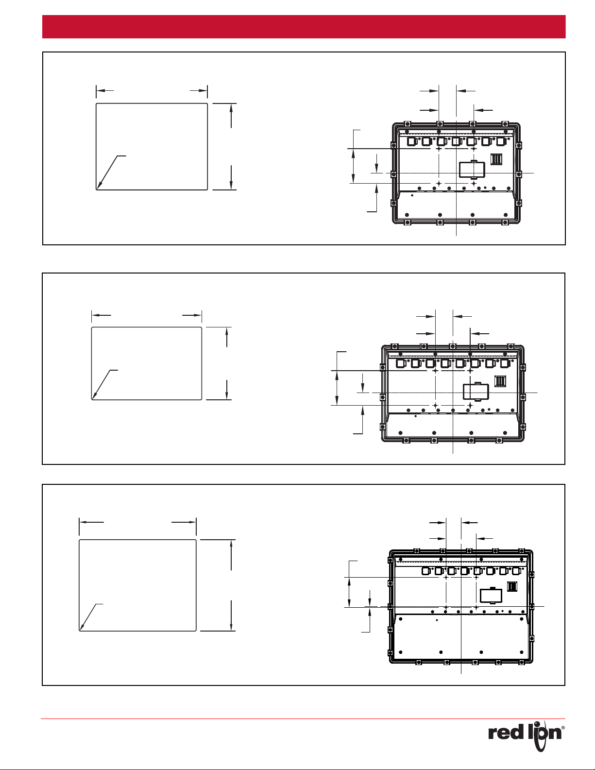
G10
.87
(22.1)
2.95 (75)
1.48 (37.5)
2.95
(75)
PANEL CUT-OUT VESA MOUNT (MIS-D 75) DIMENSIONS
10.197 (259.0)
7.931
(201.4)
4X R.10 (2.5)
MAX.
All tolerances ±.059" (±1.5 mm)
G12
PANEL CUT-OUT VESA MOUNT (MIS-D 75) DIMENSIONS
11.458 (291.0)
7.561
(192.0)
4X R.10 (2.5)
MAX.
All tolerances ±.059" (±1.5 mm)
2.95 (75)
1.48 (37.5)
1.08
(27.4)
2.95
(75)
G15
PANEL CUT-OUT VESA MOUNT (MIS-D 75) DIMENSIONS
13.390 (340.1)
10.457
(265.6)
4X R.10 (2.5)
MAX.
2.95 (75)
1.48 (37.5)
.09
(2.4)
2.95
(75)
Drawing No. LP0918
All tolerances ±.059" (±1.5 mm)
-5-
Page 6
Released 2015-11-23 Bulletin No. GRAPH-H
The protective conductor terminal is bonded to conductive
parts of the equipment for safety purposes and must be
connected to an external protective earthing system.
Steps should be taken to eliminate the buildup of
electrostatic charges including but not limited to
connecting to earth ground.
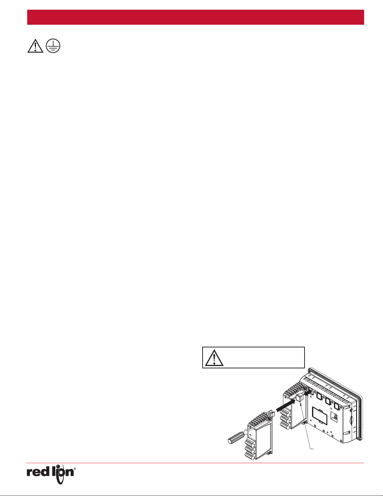
REMOVE RUBBER
MODULE PLUG
WARNING: Disconnect all power
to the unit before installing or
removing modules.
Drawing No. LP0918
CONNECTING TO EARTH GROUND
The third pin of the power connector of the G07 is chassis ground for
the unit. Your unit should be connected to earth ground (protective earth).
The chassis ground is not connected to signal common of the unit.
Maintaining isolation between earth ground and signal common is not
required to operate your unit. But, other equipment connected to this unit
may require isolation between signal common and earth ground. To
maintain isolation between signal common and earth ground care must
be taken when connections are made to the unit. For example, a power
supply with isolation between its signal common and earth ground must
be used. Also, plugging in a USB cable may connect signal common and
earth ground.
1
USB’s shield may be connected to earth ground at the host. USB’s
shield in turn may also be connected to signal common.
1
POWER SUPPLY REQUIREMENTS
The Graphite panel requires a 10-30 VDC power supply. Your unit may
draw considerably less than the maximum rated power depending upon
the features being used. As additional features are used your unit will
draw increasing amounts of power. Items that could cause increases in
current are modules, additional on-board communications, SD card, and
other features programmed through Crimson.
To ensure you do not exceed the capacity of your Graphite host power
supply, calculate the total power consumption required for all of your
planned modules. Each module’s maximum power consumption is listed
in the Specifications of their Product Bulletin. The total power available
for modules is listed in the specifications of the Graphite host.
In any case, it is very important that the power supply is mounted
correctly if the unit is to operate reliably. Please take care to observe the
following points:
– The power supply must be mounted close to the unit, with usually not
more than 6 feet (1.8 m) of cable between the supply and the operator
interface. Ideally, the shortest length possible should be used.
– The wire used to connect the operator interface’s power supply
should be at least 22-gage wire suitably rated for the temperatures
of the environment to which it is being installed. If a longer cable run
is used, a heavier gage wire should be used. The routing of the
cable should be kept away from large contactors, inverters, and
other devices which may generate significant electrical noise.
– A power supply with an NEC Class 2 or Limited Power Source (LPS)
and SELV rating is to be used. This type of power supply provides
isolation to accessible circuits from hazardous voltage levels generated
by a mains power supply due to single faults. SELV is an acronym for
“safety extra-low voltage.” Safety extra-low voltage circuits shall exhibit
voltages safe to touch both under normal operating conditions and after
a single fault, such as a breakdown of a layer of basic insulation or after
the failure of a single component has occurred. A suitable disconnect
device shall be provided by the end user.
a. Connect the shield to earth ground (protective earth) at one end
where the unit is mounted.
b. Connect the shield to earth ground at both ends of the cable, usually
when the noise source frequency is over 1 MHz.
3. Never run Signal or Control cables in the same conduit or raceway with
AC power lines, conductors, feeding motors, solenoids, SCR controls,
and heaters, etc. The cables should be run through metal conduit that
is properly grounded. This is especially useful in applications where
cable runs are long and portable two-way radios are used in close
proximity or if the installation is near a commercial radio transmitter.
Also, Signal or Control cables within an enclosure should be routed as
far away as possible from contactors, control relays, transformers, and
other noisy components.
4. Long cable runs are more susceptible to EMI pickup than short cable runs.
5. In extremely high EMI environments, the use of external EMI
suppression devices such as Ferrite Suppression Cores for signal and
control cables is effective. The following EMI suppression devices (or
equivalent) are recommended:
Fair-Rite part number 0443167251 (RLC part number FCOR0000)
Line Filters for input power cables:
Schaffner # FN2010-1/07 (Red Lion Controls # LFIL0000)
6. To protect relay contacts that control inductive loads and to minimize
radiated and conducted noise (EMI), some type of contact protection
network is normally installed across the load, the contacts or both. The
most effective location is across the load.
a. Using a snubber, which is a resistor-capacitor (RC) network or metal
oxide varistor (MOV) across an AC inductive load is very effective at
reducing EMI and increasing relay contact life.
b. If a DC inductive load (such as a DC relay coil) is controlled by a
transistor switch, care must be taken not to exceed the breakdown
voltage of the transistor when the load is switched. One of the most
effective ways is to place a diode across the inductive load. Most
RLC products with solid state outputs have internal zener diode
protection. However external diode protection at the load is always a
good design practice to limit EMI. Although the use of a snubber or
varistor could be used.
RLC part numbers: Snubber: SNUB0000
Varistor: ILS11500 or ILS23000
7. Care should be taken when connecting input and output devices to the
instrument. When a separate input and output common is provided,
they should not be mixed. Therefore a sensor common should NOT be
connected to an output common. This would cause EMI on the
sensitive input common, which could affect the instrument’s operation.
Visit RLC’s web site at http://www.redlion.net/emi for more information
on EMI guidelines, Safety and CE issues as they relate to Red Lion
Controls products.
I/O MODULE INSTALLATION
Modules must be installed beginning with slot 1 (left-most slot), with no
empty slots between the modules, and the order must match the modules
order in the Crimson database. Torque screws to 6.0 pound-force inch
[96 ounce-force inch] (0.68 N m).
EMC INSTALLATION GUIDELINES
Although Red Lion Controls Products are designed with a high degree
of immunity to Electromagnetic Interference (EMI), proper installation and
wiring methods must be followed to ensure compatibility in each
application. The type of the electrical noise, source or coupling method
into a unit may be different for various installations. Cable length, routing,
and shield termination are very important and can mean the difference
between a successful or troublesome installation. Listed are some EMI
guidelines for a successful installation in an industrial environment.
1. A unit should be mounted in a metal enclosure, which is properly
connected to protective earth.
2. Use shielded cables for all Signal and Control inputs. The shield
connection should be made as short as possible. The connection point
for the shield depends somewhat upon the application. Listed below
are the recommended methods of connecting the shield, in order of
their effectiveness.
-6-
Page 7
Released 2015-11-23 Bulletin No. GRAPH-H
WARNING - DO NOT CONNECT OR DISCONNECT CABLES
WHILE POWER IS APPLIED UNLESS AREA IS KNOWN TO BE
NON-HAZARDOUS. USB DEVICE PORT IS FOR SYSTEM SET-UP
AND DIAGNOSTICS AND IS NOT INTENDED FOR PERMANENT
CONNECTION.
TX
5V
8
1
7
2
TxB
TxA
130K
130K
5
TxEN (OC)
RX
130K
5V
130K
RxB
4
RxA
3
COMM
6
RS422/485 4-WIRE
CONNECTIONS
RS485 2-WIRE
CONNECTIONS
TxEN (OC)
TX/RX
130K
5
TxA
2
8
130K
5V
7
1
TxB
6 COMM
Drawing No. LP0918
COMMUNICATING WITH THE GRAPHITE
CONFIGURING A GRAPHITE
The Graphite is configured using Crimson® software. Crimson is
available as a free download from Red Lion’s website. Updates to
Crimson for new features and drivers are posted on the website as they
become available. By configuring the Graphite using the latest version of
Crimson, you are assured that your unit has the most up to date feature
set. Crimson software can configure the Graphite through the RS232
PGM port, USB port, or SD card.
The USB port is connected using a standard USB cable with a Type B
connector. The driver needed to use the USB port will be installed with
Crimson.
The RS232 PGM port uses a programming cable made by Red Lion to
connect to the DB9 COM port of your computer. If you choose to make
your own cable, use the “Graphite Port Pin Out Diagram” for wiring
information.
The SD card can be used to program a Graphite by placing a
configuration file and firmware on the SD card. The card is then inserted
into the target Graphite and powered. Refer to the Crimson literature for
more information on the proper names and locations of the files.
USB, DATA TRANSFERS FROM THE SD CARD
In order to transfer data from the SD card via the USB port, a driver
must be installed on your computer. This driver is installed with Crimson
and is located in the folder C:\Program Files\Red Lion Controls\Crimson
3.0\Device\ after Crimson is installed. This may have already been
accomplished if your Graphite was configured using the USB port.
Once the driver is installed, connect the Graphite to your PC with a
USB cable, and follow “Mounting the SD” instructions in the Crimson 3
user manual.
USB HOST LEDs
COLOR STATUS
OFF Not operational
RED Error
GREEN Normal operation
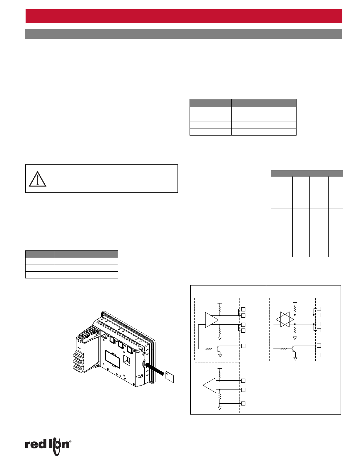
INSERTION/REMOVAL OF THE SD CARD
Insert the SD card into the slot provided with the card oriented as shown.
The card is inserted properly when the end of the card is flush with the
Graphite case. To remove the SD card, push in slightly on the card.
ETHERNET COMMUNICATIONS
Ethernet communications can be established at either 10 BASE-T or
100 BASE-TX. The Graphite unit’s RJ45 jack is wired as a NIC (Network
Interface Card). For example, when wiring to a hub or switch use a
straight-through cable, but when connecting to another NIC use a
crossover cable.
The Ethernet connector contains two LEDs. A yellow LED in the upper
right, and a green LED in the upper left. The LEDs represent the following
statuses:
LED COLOR DESCRIPTION
YELLOW solid Link established.
YELLOW flashing Data being transferred.
GREEN (OFF) 10 BASE-T Communications
GREEN (ON) 100 BASE-TX Communications
On the rear of each unit is a unique 12-digit MAC address and a block
for marking the unit with an IP address. Refer to the Crimson manual and
Red Lion’s website for additional information on Ethernet communications.
RS232 PORTS
The Graphite has two RS232
ports. There is the PGM port and the
COMMS port. Although only one of
these ports can be used for
programming, both ports can be
used for communications with a PLC.
The RS232 ports can be used for
either master or slave protocols with
any Graphite configuration.
GRAPHITE RS232 TO A PC
Gxx: RJ12 Name PC: DB9 Name
4 COMM 1 DCD
5Tx2Rx
2Rx3Tx
N/C 4 DTR
3COMM5GND
N/C 6 DSR
1 CTS 7 RTS
6 RTS 8 CTS
N/C 9 RI
RS422/485 COMMS PORT
The Graphite has one RS422/485 port. This port can be configured to
act as either RS422 or RS485.
CABLES AND DRIVERS
Red Lion has a wide range of cables and drivers for use with many
different communication types. A list of these drivers and cables along
with pin outs is available from Red Lion’s website. New cables and
drivers are added on a regular basis. If making your own cable, refer to
the “Port Pin Outs” that corresponds to your specific model for wiring
information.
Note: All Red Lion devices connect A to A and B to B. Refer to
www.redlion.net for additional information.
-7-
Page 8
Released 2015-11-23 Bulletin No. GRAPH-H
USB
TYPE B
COMM
COMM
COMM
COMM
COMM
TxA (PIN 8)
TxB (PIN 1)
RTS (PIN 6)
CTS (PIN 1)
CTS (PIN 1)
RTS (PIN 6)
RxA
RxB
TxB
TxENTxTxA
Rx
Tx
Rx
POWER
CONNECTOR
ETHERNET
(NIC)
STATUS
STATUS
USB HOST
PORT A
PORT B
COMMS PORTCOMMS PORT
RS232
PGM PORT
RS485 RS232
POWER
+
-
USB
DEVICE
PORT A (PGM)
RS232 RS232
PORT B
RS485
PORT A
+DC VOLTAGE
COMMON1CHASSIS
2
3
A
B
USB HOST
ETHERNET
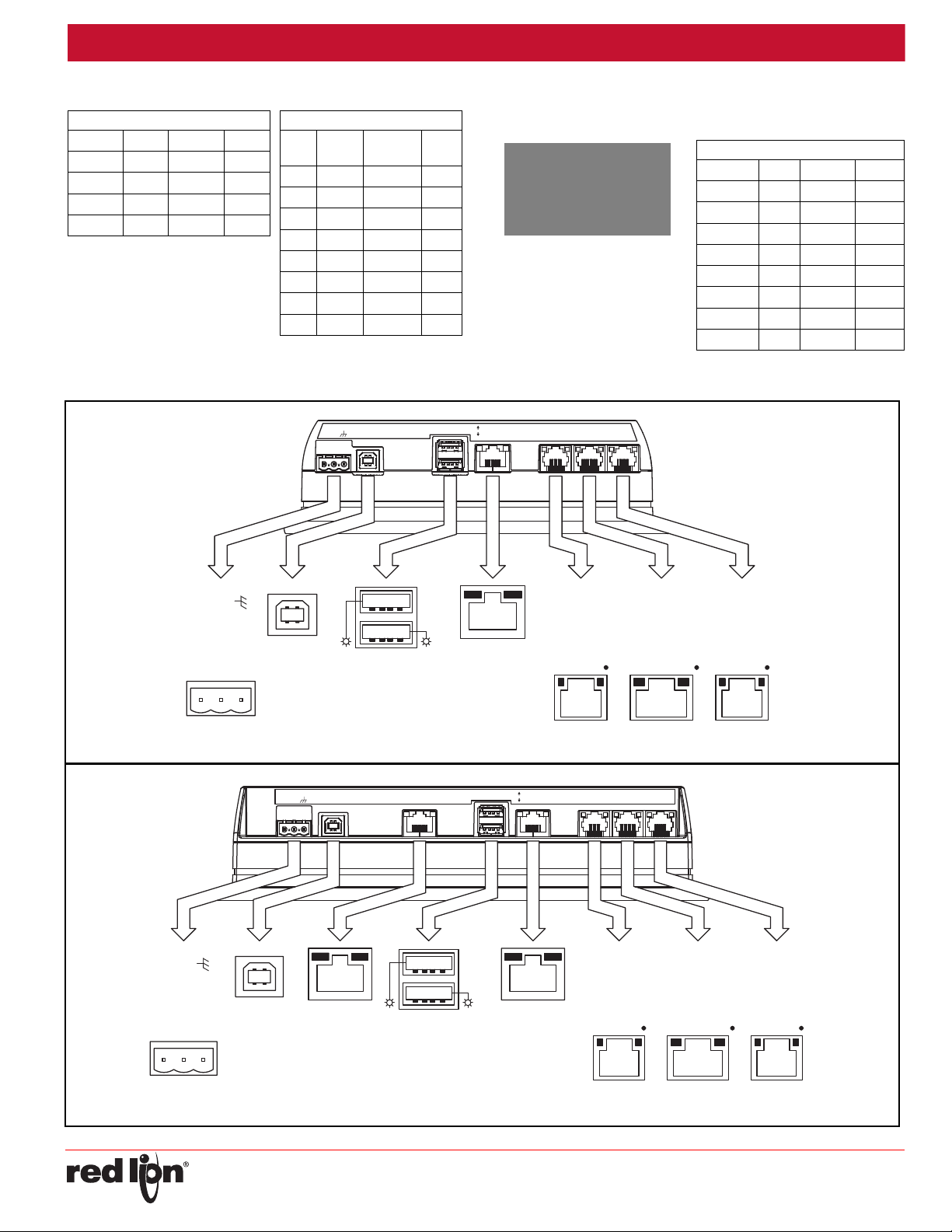
G07 PORT PIN OUTS
TYPE B
USB
STATUS
USB HOST
STATUS
PORT B
PORT A
COMM
RTS (PIN 6)TxCTS (PIN 1)
Rx
COMM
RTS (PIN 6)RxCOMMTxCOMM
CTS (PIN 1)
(NIC)
ETHERNET
RxB
TxA (PIN 8)
COMM
TxB
TxEN
TxB (PIN 1)
RxA
TxA
AUXILIARY
ETHERNET
(NIC)
COMMS PORTPGM PORT COMMS PORT
RS232 RS485 RS232
DEVICE
USBPOWER
-
+
USB HOST
PORT A (PGM)
RS232 RS232
PORT BPORT A
RS485
AUXILIARY
ETHERNET
POWER
CHASSIS
COMMON
+DC VOLTAGE
1
2
3
CONNECTOR
[OPTIONAL]
A
B
ETHERNET
G09 PORT PIN OUTS
Drawing No. LP0918
Examples of RS485 2-Wire Connections DH485 COMMUNICATIONS
The Graphite’s RS422/485 COMMS port can also be used for Allen
Graphite to Red Lion RJ11
Gxx:RJ45 Name RLC:RJ11 Name
5TxEN2 TxEN
6COMM3 COMM
1 TxB 5 B-
2 TxA 4 A+
Graphite to Modular Controller
Gxx Name
Modular
Controller
Name
1,4 TxB 1,4 TxB
4,1 RxB 4,1 RxB
2,3 TxA 2,3 TxA
3,2 RxA 3,2 RxA
5TxEN 5 TxEN
6COMM 6 COMM
7TxB 7 TxB
8TxA 8 TxA
Bradley DH485 communications.
WARNING: DO NOT use a
standard DH485 cable to
connect this port to Allen
Bradley equipment. A cable
and wiring diagram are
available from Red Lion.
Graphite to AB SLC 500
RJ45: RLC Name RJ45: A-B Name
1TxB1 A
2TxA2 B
3, 8 RxA - 24V
4, 7 RxB - COMM
5TxEN5TxEN
6 COMM 4 SHIELD
4, 7 TxB - COMM
3, 8 TxA - 24V
-8-
Page 9
Released 2015-11-23 Bulletin No. GRAPH-H
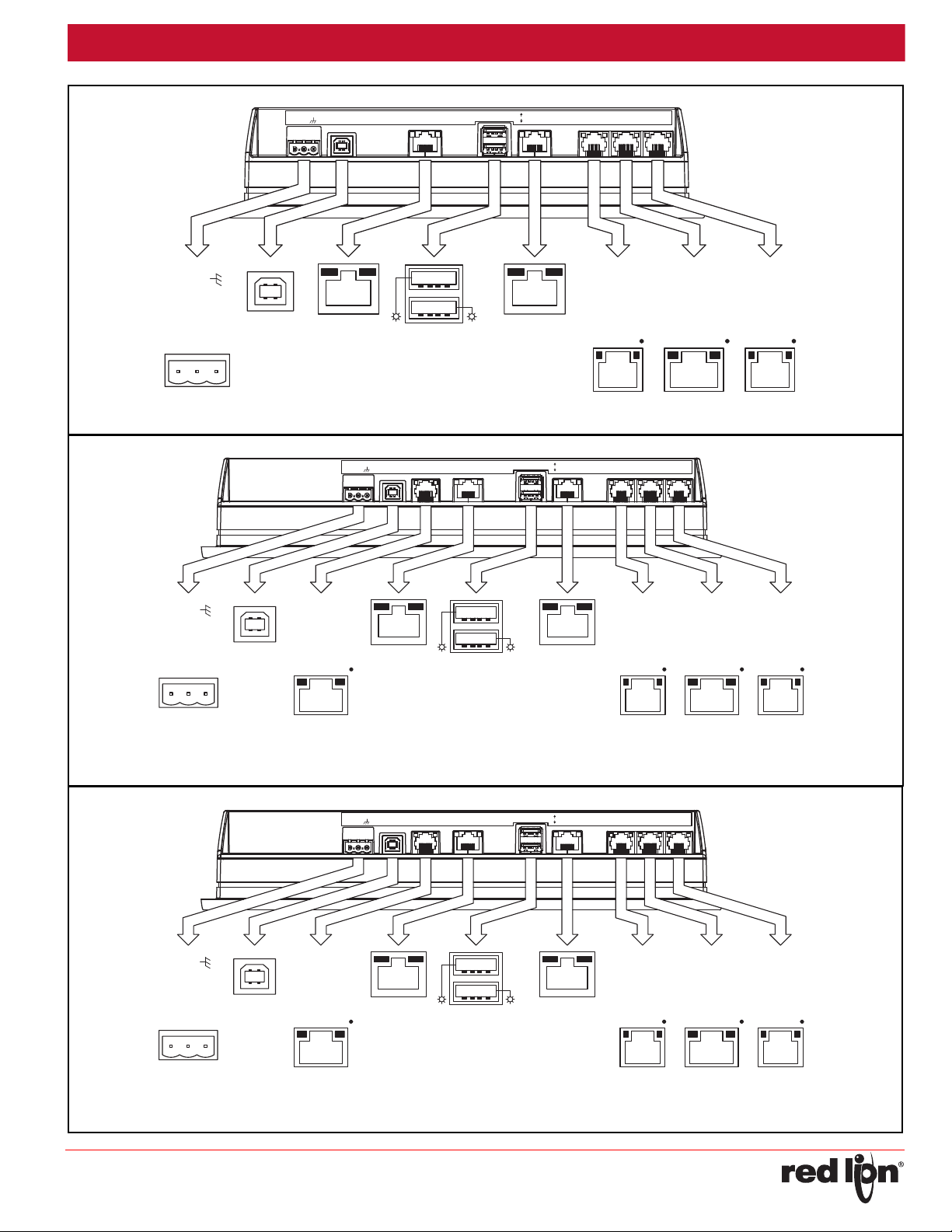
TYPE B
USB
STATUS
USB HOST
STATUS
PORT B
PORT A
COMM
RTS (PIN 6)TxCTS (PIN 1)
Rx
COMM
RTS (PIN 6)RxCOMMTxCOMM
CTS (PIN 1)
(NIC)
ETHERNET
RxB
TxA (PIN 8)
COMM
TxB
TxEN
TxB (PIN 1)
RxA
TxA
AUXILIARY
ETHERNET
(NIC)
COMMS PORTPGM PORT COMMS PORT
RS232 RS485 RS232
DEVICE
USBPOWER
-
+
USB HOST
PORT A (PGM)
RS232 RS232
PORT BPORT A
RS485
AUXILIARY
ETHERNET
POWER
CHASSIS
COMMON
+DC VOLTAGE
1
2
3
CONNECTOR
[OPTIONAL]
A
B
ETHERNET
G10 PORT PIN OUTS
TYPE B
COMMS PORT
TxB
USB
TxA (PIN 8)
TxEN
COMM
RxB
TxB (PIN 1)
TxA
RxA
PORT B
PORT A
ETHERNET
STATUS
USB HOST
(NIC)
AUXILIARY
TxA
(NIC)
STATUS
ETHERNET
COMM
RTS (PIN 6)TxCTS (PIN 1)
Rx
COMM
TxA (PIN 8)
TxB
COMM
RxB
TxEN
RxARxRTS (PIN 6)
TxB (PIN 1)
COMMTxCOMM
CTS (PIN 1)
AUXILIARY
RS485
COMMS PORT
COMMS PORTPGM PORT
RS232 RS485 RS232
DEVICE
USBPOWER
-
+
ETHERNET
AUXILIARY
PORT B
RS485
USB HOST
PORT A (PGM)
RS232
PORT B
RS232
PORT A
RS485
CONNECTOR
POWER
CHASSIS
COMMON
+DC VOLTAGE
123
[OPTIONAL]
[OPTIONAL]
A
B
ETHERNET
G12 PORT PIN OUTS
TYPE B
COMMS PORT
TxB
USB
TxA (PIN 8)
TxEN
COMM
RxB
TxB (PIN 1)
TxA
RxA
PORT B
PORT A
ETHERNET
STATUS
USB HOST
(NIC)
AUXILIARY
TxA
(NIC)
STATUS
ETHERNET
COMM
RTS (PIN 6)TxCTS (PIN 1)
Rx
COMM
TxA (PIN 8)
TxB
COMM
RxB
TxEN
RxARxRTS (PIN 6)
TxB (PIN 1)
COMMTxCOMM
CTS (PIN 1)
AUXILIARY
RS485
COMMS PORT
COMMS PORTPGM PORT
RS232 RS485 RS232
DEVICE
USBPOWER
-
+
ETHERNET
AUXILIARY
PORT B
RS485
USB HOST
PORT A (PGM)
RS232
PORT B
RS232
PORT A
RS485
CONNECTOR
POWER
CHASSIS
COMMON
+DC VOLTAGE
123
[OPTIONAL]
[OPTIONAL]
A
B
ETHERNET
G15 PORT PIN OUTS
Drawing No. LP0918
-9-
Page 10
Released 2015-11-23 Bulletin No. GRAPH-H
WARNING - EXPLOSION HAZARD - DISCONNECT POWER AND
ENSURE THE AREAS IS KNOWN TO BE NON-HAZARDOUS
BEFORE SERVICING/REPLACING THE UNIT AND BEFORE
INSTALLING OR REMOVING I/O WIRING AND BATTERY.
+
Drawing No. LP0918
SOFTWARE/UNIT OPERATION
CRIMSON® SOFTWARE
Crimson® software is available as a free download from Red Lion’s
website, see “Ordering Information” for part number. The latest version of
the software is always available from the website, and updating your copy
is free.
DISPLAY
This operator interface uses a liquid crystal display (LCD) for
displaying text and graphics. The display utilizes an LED backlight for
lighting the display. The backlight can be dimmed for low light conditions.
The LED backlight has a limited lifetime. Backlight lifetime is based
upon the amount of time the display is turned on at full intensity. Turning
the backlight off when the display is not in use can extend the lifetime of
your backlight. This can be accomplished through the Crimson
when configuring your unit.
®
software
FACTORY RESET BUTTON
The factory reset button located in the lower right area of the rear panel
can be used to access the system menu. Refer to Crimson 3 System
Menu Technical Note at www.redlion.net/TNOI46
and available options.
for access procedure
TOUCHSCREEN
This operator interface utilizes a resistive analog touchscreen for user
input. The unit will only produce an audible tone (beep) when a touch on
an active touchscreen cell is sensed. The touchscreen is fully functional
as soon as the operator interface is initialized, and can be operated with
gloved hands.
TROUBLESHOOTING YOUR GRAPHITE
If for any reason you have trouble operating, connecting, or simply
have questions concerning your new Graphite, contact Red Lion’s
technical support. For contact information, refer to the back page of this
bulletin for phone and fax numbers.
EMAIL: [email protected]
Web Site: http://www.redlion.net
BATTERY & TIME KEEPING
A battery is used to keep time when the unit is without power. Typical
accuracy (at 25°C) of the Graphite time keeping is less than one minute
per month drift. The battery of a Graphite unit does not affect the unit’s
memory, all configurations and data is stored in non-volatile memory.
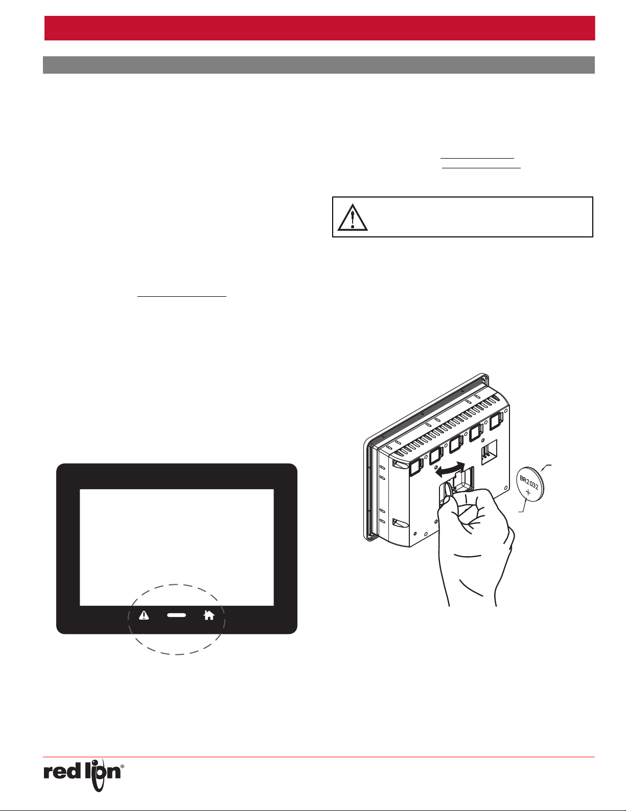
Changing the Battery
To change the battery of a Graphite, first remove power to the unit.
Remove the battery cover. Grasp the top edge of the battery and push to
the left to remove the battery from the holder. Lift the battery out and
replace with a new battery.
Replace the battery cover, and re-apply power. Using Crimson or the
unit’s keypad, enter the correct time and date.
TOUCH ICONS
There are user programmable soft keys below the display area (See
figure). These softkeys have dead-front icons and have programmable
LED backlights. Both the operation of the softkeys and the LEDs can be
configured using Crimson.
-
* Please note that the old battery must be disposed of in a manner that
complies with your local waste regulations. The battery must not be
disposed of in fire, or in a manner whereby it may be damaged and its
contents could come into contact with human skin.
The battery used by the panel is a lithium type BR2032.
-10-
Page 11
Released 2015-11-23 Bulletin No. GRAPH-H
Drawing No. LP0918
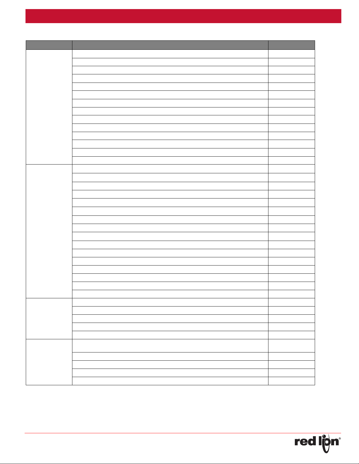
ORDERING INFORMATION
TYPE DESCRIPTION PART NUMBER
Graphite 7" Color Touch Screen, Indoor G07C0000
Graphite 7" Color Touch Screen, Indoor/Outdoor G07S0000
Graphite 9" Color Touch Screen, Indoor G09C0000
Graphite 9" Color Touch Screen, Indoor, Additional Ethernet Port G09C1000
Graphite 10" Color Touch Screen, Indoor G10C0000
Graphite 10" Color Touch Screen, Indoor, Additional Ethernet Port G10C1000
Operator
Interface Panels
Input Modules
Communications
Modules
Accessories
1
Module is not suitable for use in hazardous locations.
Graphite 10" High Resolution Display, Color Touch Screen, Indoor G10R0000
Graphite 10" High Resolution Display, Color Touch Screen, Indoor, Additional Ethernet Port G10R1000
Graphite 10" Color Touch Screen, Indoor/Outdoor G10S0000
Graphite 10" Color Touch Screen, Indoor/Outdoor, Additional Ethernet Port G10S1000
Graphite 12" Color Touch Screen, Indoor G12C0000
Graphite 12" Color Touch Screen, Indoor, Additional Ethernet And Serial Port G12C1100
Graphite 15" Color Touch Screen, Indoor G15C0000
Graphite 15" Color Touch Screen, Indoor, Additional Ethernet And Serial Port G15C1100
Graphite Module, Single PID, Relay and Analog Outputs
Graphite Module, Single PID, Relay and Heater Current Monitor
Graphite Module, Single PID, SSR and Analog Outputs GMP1SA00
Graphite Module, Single PID, SSR and Heater Current Monitor GMP1SM00
Graphite Module, Dual PID, Relay Outputs
Graphite Module, Dual PID, Relay and Heater Current Monitor
Graphite Module, Dual PID, SSR Outputs GMP2S000
Graphite Module, Dual PID, SSR and Heater Current Monitor GMP2SM00
Graphite Module, Digital I/O, 8 Inputs And 6 Relays Outputs
Graphite Module, Digital I/O, 8 Inputs And 6 Solid State Outputs GMDIOS00
Graphite Module, 4 Universal Inputs GMUIN400
Graphite Module, 4 Analog Outputs GMOUT400
Graphite Module, 8 DC Current Inputs GMINI800
Graphite Module, 8 DC Voltage Inputs GMINV800
Graphite Module, 8 Thermocouple Inputs GMTC8000
Graphite Module, 6 RTD Inputs GMRTD600
Graphite Module, CAN protocol Interface GMCAN000
Graphite Module, DeviceNet Interface GMDN0000
Graphite Module, HSPA+ Cellular Module GMHSPA00
Graphite Module, J1939 Interface GMJ19390
Graphite Module, PROFIBUS Interface GMPBDP00
50 Amp Current Transformer (For Heater Current Models) UL Recognized component, Instrument
Transformers, Inc. Part #2SFT500-0.1
2G/3G 3" hinged antenna ANT-TG090113
2G/3G/4G LTE low profile direct permanent mount antenna, IP67 rated ANT-G30B108111
2G / 3G 4 . 5" w h i p ma g net i c mou n t an t enn a , IP6 5 rat e d AN T- G A10 7 201111
2G/3G low profile direct permanent mount antenna, IP65 rated ANT-G21B301111
1
1
1
1
1
GMP1RA00
GMP1RM00
GMP2R000
GMP2RM00
GMDIOR00
CT005001
-11-
Page 12

Released 2015-11-23 Bulletin No. GRAPH-H
LIMITED WARRANTY
(a) Red Lion Controls Inc., Sixnet Inc., N-Tron Corporation, or Blue Tree Wireless Data, Inc. (the “Company”)
warrants that all Products shall be free from defects in material and workmanship under normal use for the period of
time provided in “Statement of Warranty Periods” (available at www.redlion.net) current at the time of shipment of the
Products (the “Warranty Period”). EXCEPT FOR THE ABOVE-STATED WARRANTY, COMPANY MAKES NO
WARRANTY WHATSOEVER WITH RESPECT TO THE PRODUCTS, INCLUDING ANY (A) WARRANTY OF
MERCHANTABILITY; (B) WARRANTY OF FITNESS FOR A PARTICULAR PURPOSE; OR (C) WARRANTY
AGAINST INFRINGEMENT OF INTELLECTUAL PROPERTY RIGHTS OF A THIRD PARTY; WHETHER EXPRESS
OR IMPLIED BY LAW, COURSE OF DEALING, COURSE OF PERFORMANCE, USAGE OF TRADE OR
OTHERWISE. Customer shall be responsible for determining that a Product is suitable for Customer’s use and that
such use complies with any applicable local, state or federal law.
(b) The Company shall not be liable for a breach of the warranty set forth in paragraph (a) if (i) the defect is a result
of Customer’s failure to store, install, commission or maintain the Product according to specifications; (ii) Customer
alters or repairs such Product without the prior written consent of Company.
(c) Subject to paragraph (b), with respect to any such Product during the Warranty Period, Company shall, in its
sole discretion, either (i) repair or replace the Product; or (ii) credit or refund the price of Product provided that, if
Company so requests, Customer shall, at Company’s expense, return such Product to Company.
(d) THE REMEDIES SET FORTH IN PARAGRAPH (c) SHALL BE THE CUSTOMER’S SOLE AND EXCLUSIVE
REMEDY AND COMPANY’S ENTIRE LIABILITY FOR ANY BREACH OF THE LIMITED WARRANTY SET FORTH
IN PARAGRAPH (a).
Drawing No. LP0918
-12-
 Loading...