

red lion Graphite GMDIOS00 Product Manual
Inside US: +1 (877) 432-9908 Bulletin No. GMDIO-J
C
US
U
L
R
LISTED
IND.CONT. EQ.
FOR USE IN HAZARDOUS LOCATIONS:
Class I, Division 2, Groups A, B, C, and D
T4
E317425
C
US LISTED
U
L
R
IND. CONT. EQ.
II 3 G Ex nA IIC T4 Gc
-40°C ≤ T
AMB
≤ 75°C
DEMKO 14 ATEX 1387X
IECEx UL 15.0035X
WARNING - EXPLOSION HAZARD - DO NOT D
EQUIPMENT UNLESS POWER HAS BEEN SW
OR AREA IS KNOWN TO BE NON-HAZARDOU
CAUTION: Risk of Danger.
Read complete instructions prior to installation
and operation of the unit.
WARNING - EXPLOSION HAZARD - DO NOT DISCONNECT
EQUIPMENT UNLESS POWER HAS BEEN SWITCHED OFF
OR AREA IS KNOWN TO BE NON-HAZARDOUS.
WARNING - EXPLOSION HAZARD - DO NOT DISCONNECT
EQUIPMENT UNLESS POWER HAS BEEN SWITCHED OFF
OR AREA IS KNOWN TO BE NON-HAZARDOUS.
WARNING - EXPLOSION HAZARD - SUBSTITUTION OF
COMPONENTS MAY IMPAIR SUITABILITY FOR CLASS I,
DIVISION 2.
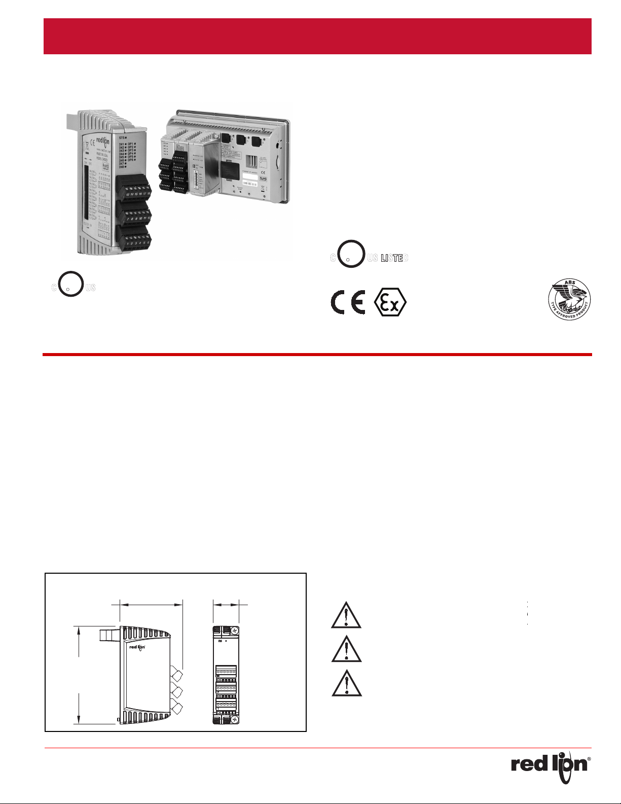
4.65
(118)
1.25 (32)
2.97 (76)
DIMENSIONSIninches(mm)
Outside US: +1 (717) 767-6511 Drawing No. LP0921
www.redlion.net Released 2018-10-31
ModelGMDIO‐Graphite®Digit alModule
• ADDS I/O CAPABILITY TO THE GRAPHITE PRODUCTS
• EIGHT INPUT, SIX OUTPUT DIGITAL MODULE
• INPUTS ISOLATED FROM OUTPUTS
• INPUTS INDEPENDENTLY SWITCH SELECTABLE FOR SINK OR
SOURCE SIGNALS
• INPUTS INDEPENDENTLY CONFIGURABLE FOR HIGH OR LOW
ACTIVE STATE
• INPUTS INDEPENDENTLY SWITCH SELECTABLE FOR HIGH OR
LOW FREQUENCY SIGNALS
• RELAY OR NFET OUTPUT MODELS AVAILABLE
E302106
ForModelNo.GMDIOS00Only
GENERALDESCRIPTION
The Model GMDIO14 module is a digital I/O module designed for use
with the Graphite products. This module offers eight inputs and six
outputs that can be used to monitor contact or sensor inputs and actuate
relays, solenoids, PLC inputs, etc.
The inputs accept standard DC inputs or contact closures, and are
configured for Sink/Source signals via external switches. Additionally,
each input has a switch selectable input filter that can be used to prevent
contact bounce. Each input may also be software configured as a highactive or low-active input.
The module is available with relay or NFET outputs that are capable of
switching up to one amp each (NFET DC only). For applications
requiring large loads to be controlled, several DIN rail mount relays are
available.
The modules connect and communicate via proprietary USB
connection to the various Graphite host devices. The Graphite host
devices, equipped with serial ports as well as an Ethernet port(s), allows
the system to share data with PCs, PLCs, and SCADA systems. The
maximum number of modules varies for each Graphite host device, see
specific models for details.
DIMENSIONSIninches(mm)
ForModelNo.GMDIOS00Only
Once programmed, the module will continue to operate/control
independent of the Graphite host device as long as power is applied.
Remove power from the host device before installing or replacing any
modules.
CONFIGURATION
The Graphite is configured with Windows® compatible Crimson
software. The software is an easy to use, graphical interface which
provides a means of configuration and commissioning of new systems,
as well as routine module re-calibration.
SAFETYSUMMARY
All safety related regulations, local codes and instructions that appear
in this literature or on equipment must be observed to ensure personal
safety and to prevent damage to either the instrument or equipment
connected to it. If equipment is used in a manner not specified by the
manufacturer, the protection provided by the equipment may be
impaired.
Do not use this unit to directly command motors, valves, or other
actuators not equipped with safeguards. To do so can be potentially
harmful to persons or equipment in the event of a fault to the unit.
®
-1-
Bulletin No. GMDIO-J Released 2018-10-31
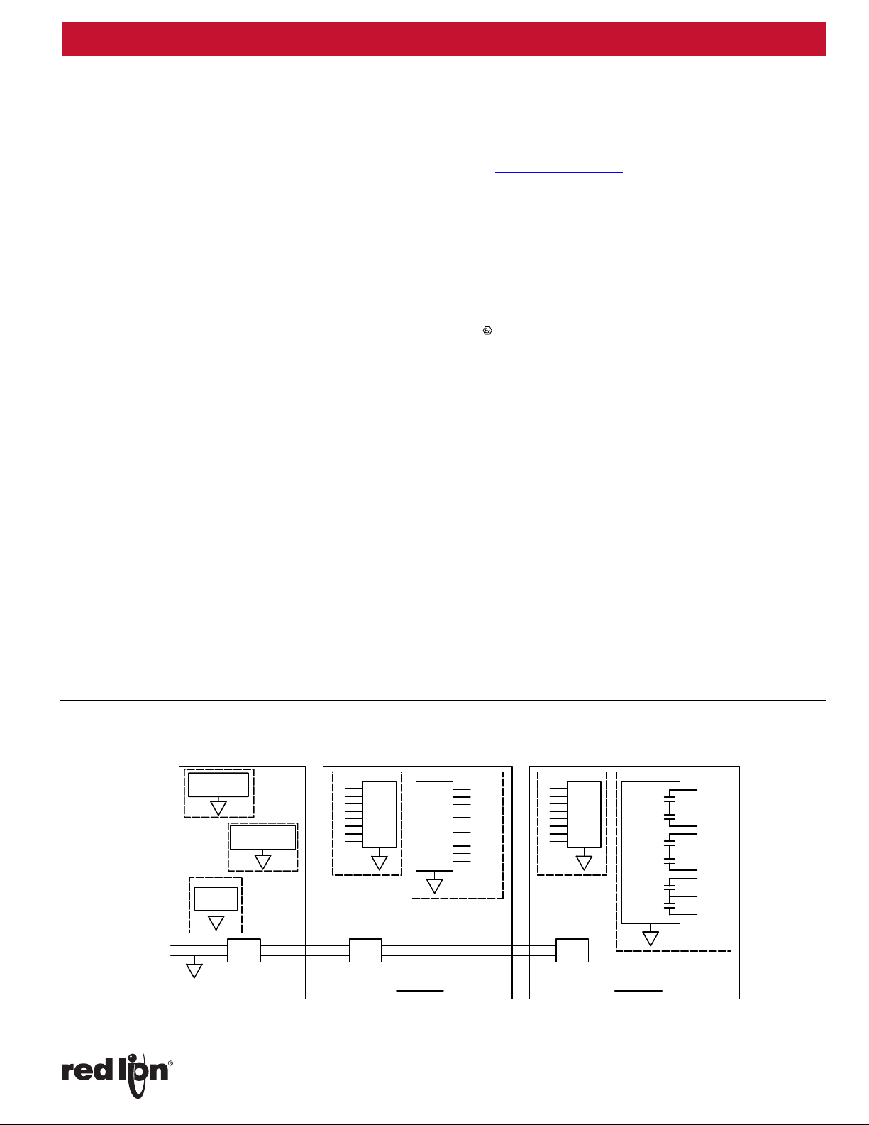
PORT 1
PROGRAMMING
A
COMMUNICATIONS
PORT 2
POWER
SUPPLY
VDC
+
-
ISOLATED
PORT 3
ETHERNET
GRAPHITE HOST
INPUTS
ISOLATED
GMDIOS00
1
8
SUPPLY
POWER
OUTPUTS
1
ISOLATED
A
B
C
D
A
NFET
2
COM 1,2
COM 3,4
4
3
COM 5,6
6
5
F
OUTPUTS
RELAY
ISOLATED
5
COM 5,6
6
COM 3,4
3
4
COM
1,2
1
2
8
E
ISOLATED
1
INPUTS
GMDIOR00
POWER
SUPPLY
Block Diagram
Drawing No. LP0921
GENERALSPECIFICATIONS
1. POWER: Power will be supplied by the Graphite host device. Some
modules, depending on usage may consume high levels of power. This
may limit the total number of modules that can be installed on a single
Graphite host. Check the Graphite module and Graphite host data
sheets for specific usage and power requirements.
GMDIO14 Max Power: 3.6 W
2. LEDs:
STS - Status LED shows module condition.
IN1-IN8 - LEDs are lit when associated input is active.
OP1-OP6 - LEDs are lit when associated output is active.
3. MEMORY: Non-volatile memory retains all programmable parameters.
4. INPUTS: DIP switch selectable for sink or source
Maximum voltage: +30 VDC, reverse polarity protected
Off Voltage: < 1.2 Volts
On Voltage: > 3.8 Volts
Input Impedance: Source Mode 10K ohms; Sink Mode 20K ohms
Input Frequency*:
Filter switch on: 50 Hz
Filter switch off: 300 Hz
* Actual useable frequency limited by communication to external
device.
5. OUTPUTS: Outputs available as FORM-A relay or Solid State NFET.
Form A Relay Output:
Type: N.O.
The following pairs of relays share the common terminal: 1&2, 3&4,
5&6
Current Rating by pair: 3 Amps @ 30 VDC / 125 VAC resistive
1/10 HP @ 125 VAC
Life Expectancy: 200,000 cycles at maximum load rating.
(Decreasing load, increasing cycle time, and use of surge
suppression such as RC snubbers increases life expectancy.)
Solid State Output:
Type: Switched DC, N Channel open drain MOSFET
All outputs share the same common
Contact Rating: 1 ADC max
VDS ON: < 0.2 V @ 1 A
VDS MAX: 30 VDC
Offstate Leakage Current: 0.5 mA max
6. ISOLATION LEVEL: 500 Vrms @ 50/60 Hz for 1 minute between the
following:
Inputs
Outputs
Graphite Host Power Supply Input
7. COMMUNICATIONS: Provided by the Graphite host device
8. ENVIRONMENTAL CONDITIONS:
Operating Temperature Range:
GMDIOR00: -40 to 70 °C
GMDIOS00: -40 to 75 °C
Operating temperature is limited to lowest range among equipment
used in your Graphite system. Consult the user manual or
www.redlion.net/OpTemp
for further details.
Storage Temperature Range: -40 to +85 °C
Shock to IEC 68-2-27: Operational 40 g (10 g, modules w/relays)
Operating and Storage Humidity: 85% max. Relative humidity, non-
condensing
Altitude: Up to 2000 meters
9. CERTIFICATIONS AND COMPLIANCES:
CE Approved
EN 61326-1 Immunity to Industrial Locations
IEC/EN 61010-1
RoHS Compliant
ATEX Approved (GMDIOS00 only)
II 3 G Ex nA IIC T4 Gc
DEMKO 14 ATEX 1387X
EN 60079-0, -15
IECEx Approved (GMDIOS00 only)
Ex nA IIC T4 Gc
IECEx UL 15.0035X
IEC 60079-0, -15
UL Listed: File #E302106
UL Hazardous: File #E317425 (GMDIOS00 only)
ABS Type Approval for Shipboard Applications
10.CONSTRUCTION: Case body is all metal construction.
11.CONNECTIONS: Removable wire clamp screw terminal blocks
Wire Gage: 28-16 AWG (0.32 mm - 1.29 mm) terminal gage wire
Torque: 1.95-2.21 inch-lbs (0.22-0.25 N-m)
12.MOUNTING: Screws to host
13.WEIGHT: 8 oz (224 g)
-2-
Released 2018-10-31 Bulletin No. GMDIO-J
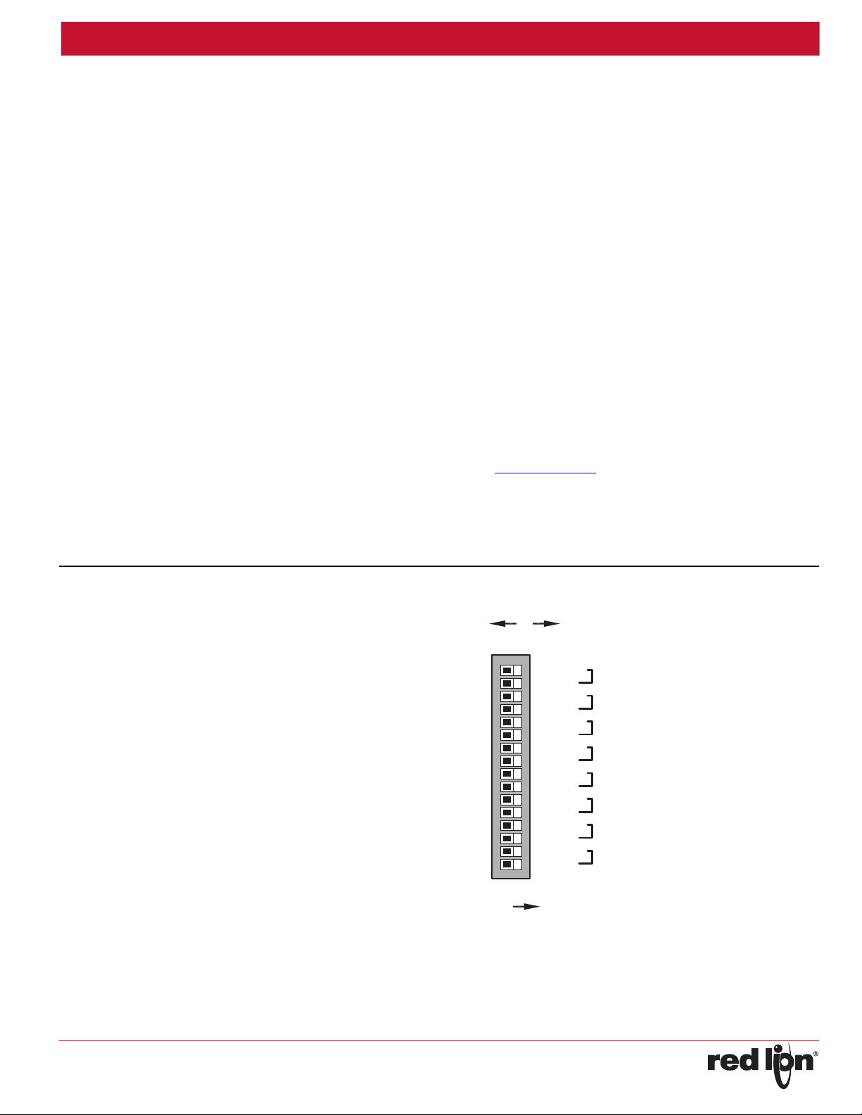
INPUT SWITCHES
FILTER ON
FILTER
SNK/SRC
FILTER
SNK/SRC
7
8
FILTER
SNK/SRC
SNK/SRC
FILTER
FILTER
SNK/SRC
FILTER
SNK/SRC
FILTER
SNK/SRC
SNK/SRC
FILTER
5
6
4
2
3
1
SNK SRC
Drawing No. LP0921
EMCINSTALLATIONGUIDELINES
Although Red Lion Controls products are designed with a high degree
of immunity to Electromagnetic Interference (EMI), proper installation and
wiring methods must be followed to ensure compatibility in each
application. The type of the electrical noise, source or coupling method
into a unit may be different for various installations. Cable length, routing,
and shield termination are very important and can mean the difference
between a successful or troublesome installation. Listed are some EMI
guidelines for a successful installation in an industrial environment.
1. A unit should be mounted in a metal enclosure, which is properly
connected to protective earth.
2. Use shielded cables for all Signal and Control inputs. The shield
connection should be made as short as possible. The connection point
for the shield depends somewhat upon the application. Listed below
are the recommended methods of connecting the shield, in order of
their effectiveness.
a. Connect the shield to earth ground (protective earth) at one end
where the unit is mounted.
b. Connect the shield to earth ground at both ends of the cable, usually
when the noise source frequency is over 1 MHz.
3. Never run Signal or Control cables in the same conduit or raceway with
AC power lines, conductors, feeding motors, solenoids, SCR controls,
and heaters, etc. The cables should be run through metal conduit that
is properly grounded. This is especially useful in applications where
cable runs are long and portable two-way radios are used in close
proximity or if the installation is near a commercial radio transmitter.
Also, Signal or Control cables within an enclosure should be routed as
far away as possible from contactors, control relays, transformers, and
other noisy components.
4. Long cable runs are more susceptible to EMI pickup than short cable runs.
5. In extremely high EMI environments, the use of external EMI
suppression devices such as Ferrite Suppression Cores for signal and
control cables is effective. The following EMI suppression devices (or
equivalent) are recommended:
Fair-Rite part number 0443167251 (Red Lion Controls #FCOR0000)
Line Filters for input power cables:
Schaffner # FN2010-1/07 (Red Lion Controls #LFIL0000)
6. To protect relay contacts that control inductive loads and to minimize
radiated and conducted noise (EMI), some type of contact protection
network is normally installed across the load, the contacts or both. The
most effective location is across the load.
a. Using a snubber, which is a resistor-capacitor (RC) network or metal
oxide varistor (MOV) across an AC inductive load is very effective at
reducing EMI and increasing relay contact life.
b. If a DC inductive load (such as a DC relay coil) is controlled by a
transistor switch, care must be taken not to exceed the breakdown
voltage of the transistor when the load is switched. One of the most
effective ways is to place a diode across the inductive load. Most
Red Lion products with solid state outputs have internal zener diode
protection. However external diode protection at the load is always a
good design practice to limit EMI. Although the use of a snubber or
varistor could be used.
Red Lion part numbers: Snubber: SNUB0000
7. Care should be taken when connecting input and output devices to the
instrument. When a separate input and output common is provided,
they should not be mixed. Therefore a sensor common should NOT be
connected to an output common. This would cause EMI on the
sensitive input common, which could affect the instrument’s operation.
Visit www.redlion.net/emi
Safety and CE issues as they relate to Red Lion products.
Varistor: ILS11500 or ILS23000
for more information on EMI guidelines,
HARDWARE
INPUTSWITCHES
Each input is independently configurable for sinking or sourcing
signals. A filter capacitor is also selectable for avoiding contact bounce.
SNK/SRC:
ON-SRC - Connects an internal 10K pull-down resistor to common.
OFF-SNK - Connects an internal 20K pull-up resistor to +5V.
FILTER:
ON - Connects a capacitor to the input, thereby reducing the input
response to 50 Hz.
OFF - Provides maximum input response of 300 Hz.
-3-
 Loading...