

red lion GRAPHITE G07C, GRAPHITE G07S, GRAPHITE G09, GRAPHITE G10C, GRAPHITE G12 User Manual
...
Bulletin No. GRAPH-G
C
LISTED
Drawing No. LP0918
Released 05/15
Tel +1 (717) 767-6511
Fax +1 (717) 764-0839
www.redlion.net
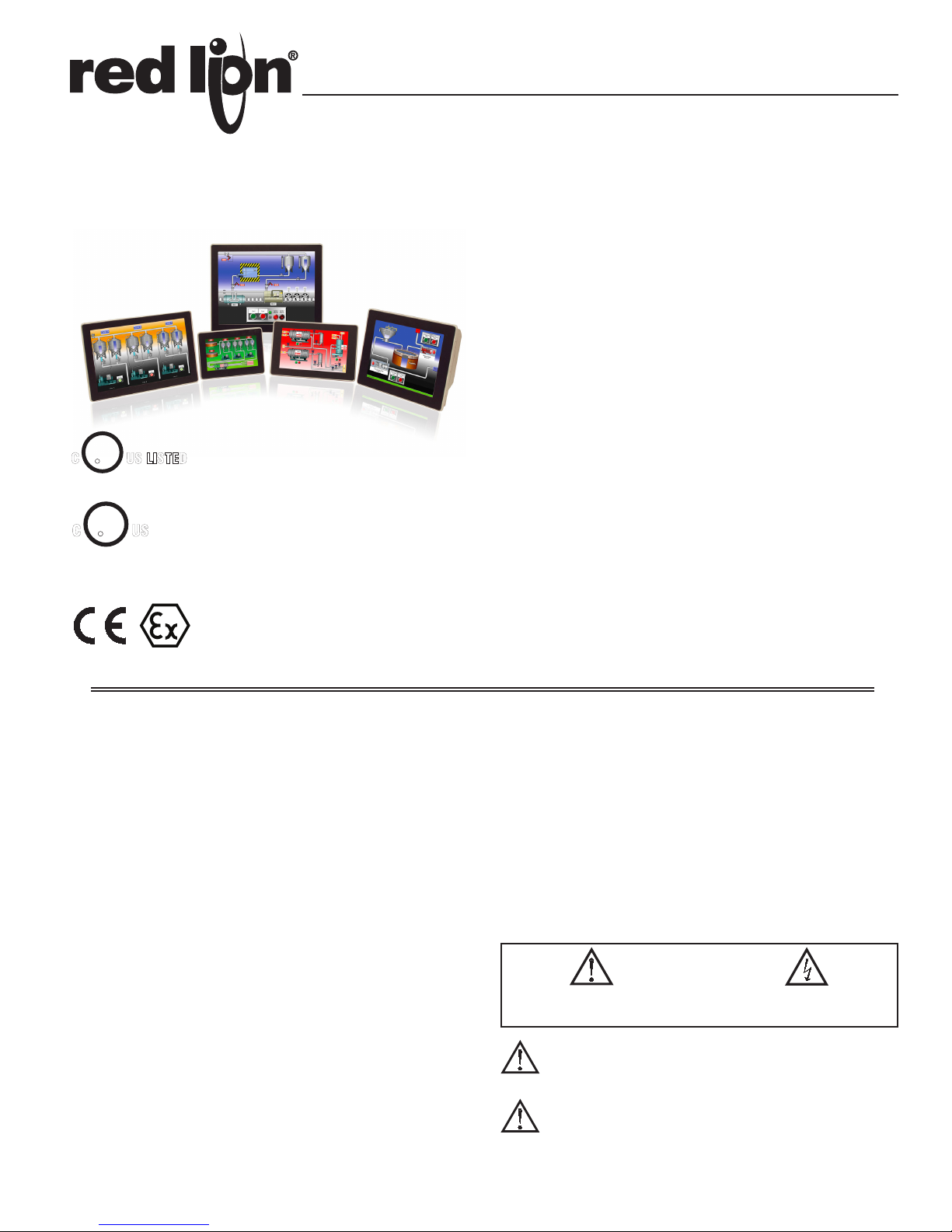
GRAPHITE™ SERIES - OPERATOR INTERFACE TERMINALS WITH
PLUG-IN I/O MODULE CAPABILITY
z PROTOCOL CONVERSION FEATURE CONVERTS NUMEROUS
PROTOCOLS SIMULTANEOUSLY
z OVER 250 BUILT-IN DRIVERS ALLOWS EASY DATA MAPPING TO
PLCS, PCS, AND SCADA SYSTEMS
z BUILT-IN WEB SERVER ALLOWS REMOTE VIEW OR CONTROL
FROM ANY INTERNET CONNECTED PC OR SMART PHONE
U
R
L
U
R
C
L
IND.CONT. EQ.
3PWL
US LISTED
IND. CONT. EQ.
34AD
FOR USE IN HAZARDOUS LOCATIONS:
US
Class I, Division 2, Groups A, B, C, and D
Class II, Division 2, Groups F and G
Class III, Division 2
II 3 G Ex ic nA IIC T4 Gc
II 3 D Ex tc IIIC T135°C Dc
DEMKO 14 ATEX 1387X
IECEx UL 15.0035X
z SYNCS DATA LOGS TO FTP SERVERS AND MICROSOFT SQL
SERVER
z PROVIDES EMAIL AND SMS TEXT MESSAGE ALERTS
z CONFIGURED USING CRIMSON® 3 SOFTWARE
z UP TO 4 FULLY ISOLATED SERIAL COMMUNICATION PORTS,
(2 RS-232 AND 1 RS-422/485)
z 10 BASE T/100 BASE-TX ETHERNET CONNECTION CAN
CONNECT TO AN UNLIMITED NUMBER OF DEVICES VIA TEN
PROTOCOLS SIMULTANEOUSLY
z EASY TO ADD I/O CAPABILITY WITH GRAPHITE PLUG-IN
MODULES
z ALUMINUM CASE CONSTRUCTION FOR BOTH THE OPERATOR
INTERFACE TERMINAL AND THE I/O MODULES
®
GENERAL DESCRIPTION
The Graphite™ Series merges two of our most highly successful product
platforms into a single, extremely flexible solution. The nexus of the product is
the operator interface panel which offers the award winning technology of our
G3 HMI Series including protocol conversion, data logging and remote access.
Programming the unit is easy using drag and drop selection within our Crimson
3 software allowing complete set-up in minutes. Add to all that capability, plugin modules which provide I/O functions within the framework of the operator
interface panel. The I/O modules are similar to our Modular Controller Series
product providing easy interface of sensors, discreet outputs and communication
modules. The result is a complete industrial solution that connects, monitors,
and controls while providing real time displays.
The operator interface panels are available in 5 different panel sizes; 7", 9",
10", 12" and 15", with the 7", 9" and 12" displays in the wide screen format. The
displays are full color touch panels in VGA, SVGA or XGA formats and operate
as full touchscreens. The all-aluminum construction provides very robust
packaging that can withstand even the most demanding environments. If your
application calls for outdoor use, we have two models, 7"and 10" that are
designed for just that requirement.
The units are able to communicate with many types of hardware simultaneously
using high-speed RS-232/485 communication ports and Ethernet 10 Base T/100
Base-TX communications. Currently over 250 drivers are selectable in the
Crimson Software which allows easy data mapping to PLCs, PCs, and SCADA
Systems. In addition, the Graphite Series features USB host capability for fast
downloads of configuration files and access to trending and data logging
information.
CONTENTS OF PACKAGE
- Operator Interface.
- Panel gasket.
- Hardware packet for mounting unit into panel.
- Terminal block for connecting power.
SAFETY SUMMARY
All safety related regulations, local codes and instructions that appear in the
manual or on equipment must be observed to ensure personal safety and to
prevent damage to either the instrument or equipment connected to it. If
equipment is used in a manner not specified by the manufacturer, the protection
provided by the equipment may be impaired.
Do not use the controller to directly command motors, valves, or other
actuators not equipped with safeguards. To do so can be potentially harmful to
persons or equipment in the event of a fault to the controller.
CAUTION: Risk Of Danger.
Read complete instructions prior to
installation and operation of the unit.
WARNING - EXPLOSION HAZARD - DO NOT DISCONNECT
EQUIPMENT UNLESS POWER HAS BEEN SWITCHED OFF
OR AREA IS KNOWN TO BE NON-HAZARDOUS.
WARNING - EXPLOSION HAZARD - SUBSTITUTION OF
COMPONENTS MAY IMPAIR SUITABILITY FOR CLASS I,
DIVISION 2
CAUTION: Risk of electric shock.
1
SpecificationS
1. POWER REQUIREMENTS: +24 VDC ±20%
Must use a Class 2 circuit according to National Electrical Code (NEC),
NFPA-70 or Canadian Electrical Code (CEC), Part I, C22.1 or a Limited
Power Supply (LPS) according to IEC 60950-1 or Limited-energy circuit
according to IEC 61010-1.
Power connection via removable three position terminal block.
G07C G07S G09 G10C/R G10S G12 G15
Typical Power
HMI only:
Maximum Power
HMI only:
Available Power
for Modules:
Maximum Power
HMI w/ Module(s):
9 W 10 W 13 W 12 W 18 W 16 W 20 W
16 W 17 W 20 W 19 W 24 W 23 W 27 W
21 W 21 W 25 W 29 W 29 W 33 W 33 W
37 W 38 W 45 W 48 W 53 W 56 W 60 W
2. BATTERY: Lithium coin cell. Typical lifetime of 6 years, nominal.
3. LCD DISPLAY: See Table below for detailed display specifications.
4. TOUCHSCREEN: Resistive analog
5. MEMORY:
On Board User Memory: 256 Mbyte of non-volatile Flash memory.
Memory Card: SD slot accepts standard capacity cards up to 2Gbyte.
6. COMMUNICATION CAPABILITIES:
USB Port: Adheres to USB specification 2.0 (high speed, full speed) only
using Type B connection.
WARNING - Do not connect or disconnect cables while
power is applied unless area is known to be non-hazardous.
USB port is for system set-up and diagnostics and is not
intended for permanent connection.
USB Host Ports: Comply with Universal Serial Bus Specification Rev 2.0.
Support data transfers at (high speed, full speed). Hardware over current
protected (0.5 A max per port).
Serial Ports: Ports are individually isolated. Format and Baud Rates for each
port are individually software programmable up to 115,200 baud.
PGM Port: RS232 port via RJ12.
COMMS Ports: RS422/485 port via RJ45, and RS232 port via RJ12.
DH485 TXEN: Transmit enable; open collector, VOH = 15 VDC,
VOL = 0.5 V @ 25 mA max.
Port to Port Isolation: 1000 Vrms (G07: 500 Vrms) for 1 minute. Signal
Isolation: 50 V.
Ethernet Port: 10 BASE-T / 100 BASE-TX
RJ45 jack is wired as a NIC (Network Interface Card).
Isolation from Ethernet network to Graphite operator interface: 1500 Vrms
7. ENVIRONMENTAL CONDITIONS:
Operating Temperature Range: -20 to 60 °C
Storage Temperature Range: -20 to 70 °C
Vibration to IEC 68-2-6: Operational 5-500 Hz, 4 g
Shock to IEC 68-2-27: Operational 40 g (10 g, modules w/relays)
Operating and Storage Humidity: 0 to 85% max. RH non-condensing
Altitude: Up to 2000 meters
8. CERTIFICATIONS AND COMPLIANCES:
CE Approved
EN 61326-1 Immunity to Industrial Locations
Emission CISPR 11 Class A
IEC/EN 61010-1
RoHS Compliant
ATEX Approved
II 3 G Ex ic nA IIC T4 Gc
II 3 D Ex tc IIIC T135°C Dc
DEMKO 14 ATEX 1387X
EN 60079-0, -11, -15, -31
IECEx Approved
Ex ic nA IIC T4 Gc
Ex tc IIIC T135°C Dc
IECEx UL 15.0035X
IEC 60079-0, -11, -15, -31
UL Listed: File #E302106
UL Hazardous: File #E317425
Type 4X Indoor / IP66 Enclosure rating (Face only) for all models
Type 4X Outdoor Enclosure rating (Face only) for GxxSxxxx models
9. CONNECTIONS: High compression cage-clamp terminal block
Wire Strip Length: 0.3" (7.5 mm)
Wire Gauge Capacity: One 14 AWG (1.63 mm) solid,
two 18 AWG (1.02 mm) or four 20 AWG (0.81 mm)
10. CONSTRUCTION: Cast aluminum enclosure with NEMA 4X/IP66 rating
for indoor use only when correctly fitted with the gasket provided. Installation
Category II, Pollution Degree 2 as defined in IEC 60664-1. These devices
have only been evaluated for low risk of mechanical impact.
11. MOUNTING REQUIREMENTS: Maximum panel thickness is 0.188"
(4.78 mm) with removable foot, or 0.375" (9.53 mm) without foot. For
NEMA 4X/IP66 sealing, a steel panel with a minimum thickness of 0.125"
(3.17 mm) is recommended.
Maximum Mounting Screw Torque: 6.0 lbf inch (96 ozf inch) (0.68 Nm)
12. WEIGHT:
G07: 2.26 lb. (1.03 Kg)
G09: 3.39 lb. (1.54 Kg)
G10: 4.8 lb. (2.18 Kg)
G12: 5.06 lb. (2.29 Kg)
G15: 7.73 lb. (3.5 Kg)
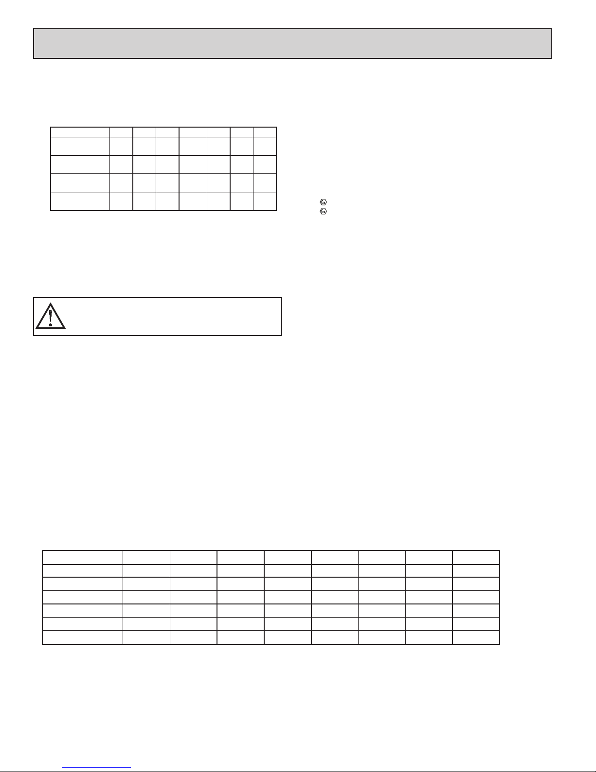
LCD DISPLAY:
G07C G07S G09 G10C G10R G10S G12 G15
SIZE 7 - inch 7 - inch 9 - inch 10 - inch 10 - inch 10 - inch 12 - inch 15 - inch
COLORS
PIXELS
BRIGHTNESS
BACKLIGHT (HR TYP.) *
BACKLIGHT TYPE
* Lifetime at room temperature (25°C)
WVGA, 16 M WVGA, 16 M WVGA, 16 M VGA, 16 M SVGA, 16 M VGA, 16 M WXGA, 16 M XGA, 16 M
800 X 480 800 X 480 800 X 480 640 X 480 800 X 600 640 X 480 1280 X 800 1024 X 768
500 cd/m21000 cd/m2400 cd/m2450 cd/m2400 cd/m22500 cd/m2400 cd/m2400 cd/m
40,000 40,000 70,000 70,000 70,000 35,000 70,000 70,000
LED LED LED LED LED LED LED LED
2
2
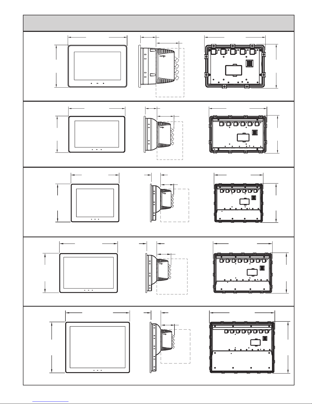
DimenSionS in inches (mm)
G07
G09
G10
5.51
(139.9)
6.47
(164.4)
7.70 (195.5) 2.00 (50.8)
Module sold
separately
10.06 (255.6)
10.84 (275.2)
2.06 (52.4)
Module sold
separately
2.97 (76)
2.97 (76)
2.06 (52.4)
7.9 (202)
(MOUNTING CLIPS INSTALLED)
10.3 (262)
(MOUNTING CLIPS INSTALLED)
11.1 (281)
5.7
(146)
6.7
(171)
G12
G15
8.20
(208.3)
8.57
(217.7)
12.10 (307.3)
14.03 (356.3)
2.97 (76)
Module sold
separately
2.06 (52.4)
2.97 (76)
Module sold
separately
2.14 (54.3)
2.97 (76)
8.8
(224)
(MOUNTING CLIPS INSTALLED)
12.3 (314)
8.4
(215)
(MOUNTING CLIPS INSTALLED)
14.3 (363)
11.10
(281.8)
11.3
(288)
Module sold
separately
(MOUNTING CLIPS INSTALLED)
3
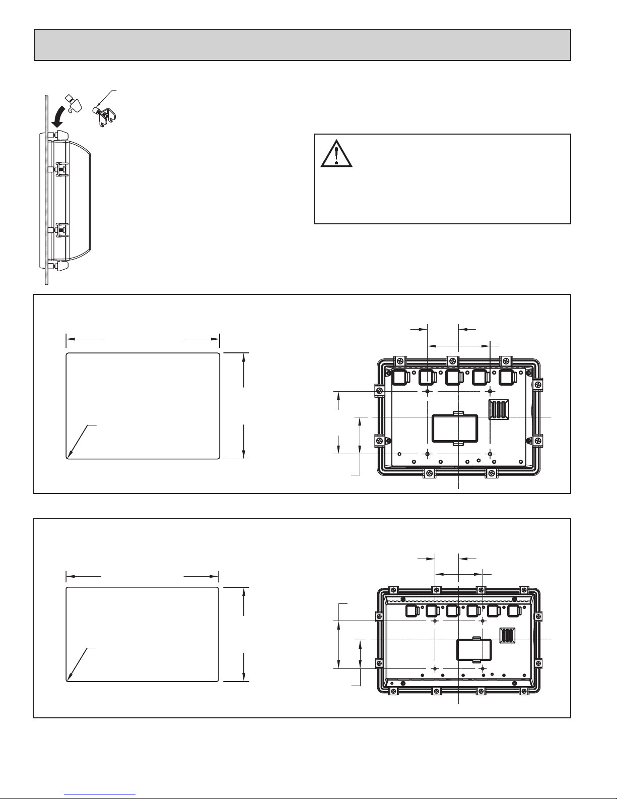
operator interface inStallation
FOOT MAY BE REMOVED
FOR THICKER PANEL
INSTALLATIONS
MOUNTING INSTRUCTIONS
This operator interface is primarily designed for
through-panel mounting. Four VESA mount tapped
screw-holes (M4 x 0.7, 5 mm deep) are present on the rear
of the panel to allow for stand or wall mounting. Care
should be taken to remove any loose material from the
mounting cut-out to prevent that material from falling into
the operator interface during installation. A gasket is
provided to enable sealing to NEMA 4X/IP66
specification. Install the mounting clips provided and
tighten to 6.0 pound-force inch (96 ounce-force inch)
(0.68 Nm) evenly for uniform gasket compression.
Provisions should be made to prohibit the product from
being exposed to UV radiation while in use. Care should
be taken not to rub or buff the touchscreen surface in a
way that might cause the accumulation of static charges.
of not more than Pollution Degree 2 per EN 60664-1. Must be wired
using Division 2 wiring methods as specified in article 501-4 (b),
502-4 (b), and 503-3 (b) of the National Electrical Code, NFPA 70 for
installation within the United States, or as specified in section 19-152
of Canadian Electrical Code for installation in Canada.
For hazardous location installation, this device must be
mounted in a suitable ATEX/IECEx certified end-enclosure
with a minimum ingress protection rating of at least IP66
as defined in EN/IEC 60529 and used in an environment
G07
G09
PANEL CUT-OUT
7.060 (179.3)
4X R.10 (2.5)
MAX.
All tolerances ±.059" (±1.5 mm)
PANEL CUT-OUT
9.423 (239.3)
4X R.10 (2.5)
MAX.
4.869
(123.7)
5.832
(148.1)
VESA MOUNT (MIS-D 75) DIMENSIONS
1.48 (37.5)
2.95 (75)
2.95
(75)
1.73
(44)
VESA MOUNT (MIS-D 75) DIMENSIONS
1.48 (37.5)
2.95 (75)
2.95
(75)
All tolerances ±.059" (±1.5 mm)
1.77
(45)
44
 Loading...