

Page 1
Bulletin No. GRAC1-A
C
US LISTED
U
L
R
IND. CONT
C
US
U
L
R
LISTED
IND.CONT. EQ.
Drawing No. LP0994
Effective 2017-01-27
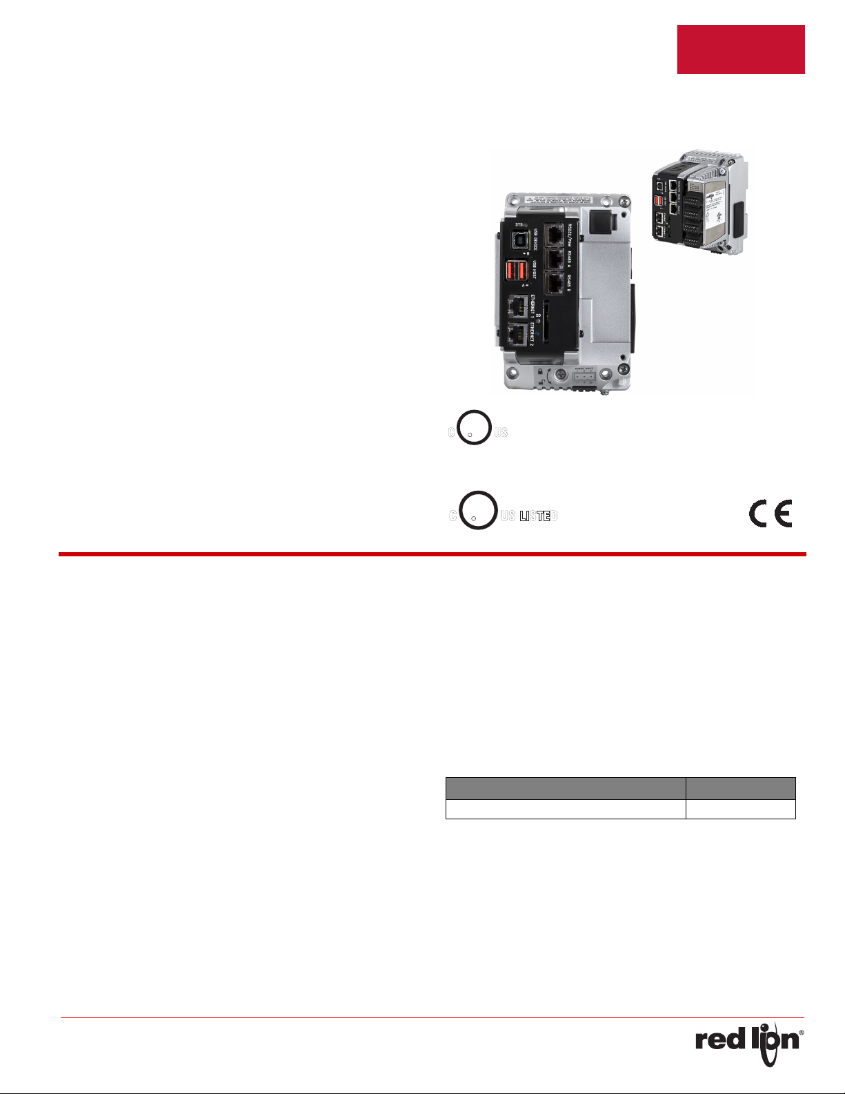
MODELGRAC0001‐Graphit e®EdgeContr ollerWithPlug‐InI/OModule
andPr otocolConversionCapability
• RUGGED CONTROLLER WITH BUILT-IN CONTROL ENGINE
• PROTOCOL CONVERSION FEATURE CONVERTS 13
PROTOCOLS SIMULTANEOUSLY
• OVER 300 BUILT-IN DRIVERS ALLOWS EASY DATA MAPPING
TO PLCs, PCs, AND SCADA SYSTEMS
• BUILT-IN WEB SERVER ALLOWS REMOTE VIEW OR CONTROL
FROM ANY INTERNET-CONNECTED PC OR SMART PHONE
• SYNCS DATA LOGS TO FTP SERVERS AND MICROSOFT SQL
SERVER
• PROVIDES EMAIL AND SMS TEXT MESSAGE ALERTS
(SMS Requires GMHSPA00 module)
• CONFIGURED USING CRIMSON
CONTROL
• 3 FULLY ISOLATED SERIAL COMMUNICATION PORTS
(1 RS232 and 2 RS422/485)
• 2 10 BASE T/100 BASE-TX ETHERNET CONNECTIONS CAN
CONNECT TO AN UNLIMITED NUMBER OF DEVICES VIA TEN
PROTOCOLS SIMULTANEOUSLY
• INTEGRATED GRAPHITE RACK EXPANSION PORT. ADD UP TO
4 GEXRACK2 3 PORT EXPANSION RACKS.
• CAST ALUMINUM CASE CONSTRUCTION SUPPORTS DIN RAIL
AND PANEL MOUNT
®
®
3 SOFTWARE WITH CRIMSON
FOR USE IN HAZARDOUS LOCATIONS:
Class I, Division 2, Groups A, B, C, and D
3PWL
. EQ.
34AD
GENERALDESCRIPTION
The Graphite
monitor and control equipment in process applications. At the core of the
product is Crimson
engine, that can be configured via Ladder, Function Block, Structured
Text, and Instruction List. Additionally, the Graphite Edge Controller is
optimized for multi-vendor environments with powerful protocol
conversion, built-in data logging and a virtual operator interface for
remotely viewing equipment and processes. The Edge Controller can be
expanded to meet almost any application requirement through the use of
plug-in digital and analog I/O modules that leverage the Graphite
Expansion Racks. The integrated rack port supports 4 GEXRACK2
bases (12 modules). An additional 12 modules can be added using the
USB host port (GEXRACK1, 3 GEXRACK2).
Red Lion’s industry leading protocol library offers access to over 300
drivers including PLCs, drives, cameras, bar code readers and many
other devices providing easy data mapping to PLCs, PCs, and SCADA
Systems. In addition, the Edge Controller can convert over 13 protocols
simultaneously, seamlessly connecting and communicating with
disparate devices. Graphite Edge Controllers offer numerous
communication ports including high-speed RS-232/485 and 10/100BaseT(X) Ethernet ports. Additionally, the Edge Controller features built-in
USB host ports for fast downloads of configuration files and access to
trending and data logging information. Eliminate the need for external
protocol converters and use an Edge Controller to connect and control to
all your devices.
The Graphite Edge Controller can be programmed with Red Lion’s
Crimson 3.0 software using a simple drag and drop interface to configure
data tags, virtual displays, protocol conversion and data logging in
minutes. Embedded in Crimson 3.0 software platform is the IEC 61131
control engine, Crimson Control which can be written in 4 programming
languages including Ladder, Function Block, Structured Text, and
Instruction List. The controller comes with Crimson Control functionality
®
Edge Controller is designed to remotely connect,
®
3.0 featuring an embedded IEC61131 control
enabled, without the need for additional equipment or modules.
Red Lion’s Edge Controller is housed in an all-aluminum housing,
which provides reliable operation that can withstand even the most
demanding environments. The result is an industrially-hardened solution
that connects, monitors, and controls disparate equipment in multivendor applications.
CONTENTSOFPACKAGE
- Graphite Edge Controller
- Terminal block for connecting power.
- (1) Module port cover
- Downstream port cover
- User Bulletin
ORDERINGINFORMATION
DESCRIPTION PART NUMBER
Graphite Edge Controller GRAC0001
SAFETYSUMMARY
All safety related regulations, local codes and instructions that appear
in the manual or on equipment must be observed to ensure personal
safety and to prevent damage to either the instrument or equipment
connected to it. If equipment is used in a manner not specified by the
manufacturer, the protection provided by the equipment may be
impaired.
Do not use the controller to directly command motors, valves, or other
actuators not equipped with safeguards. To do so can be potentially
harmful to persons or equipment in the event of a fault to the unit.
-1-
Page 2
Effective 2017-01-27 Bulletin No. GRAC1-A
WARNING - DO NOT CONNECT OR DISCONNECT CABLES
WHILE POWER IS APPLIED UNLESS AREA IS KNOWN TO BE
NON-HAZARDOUS.
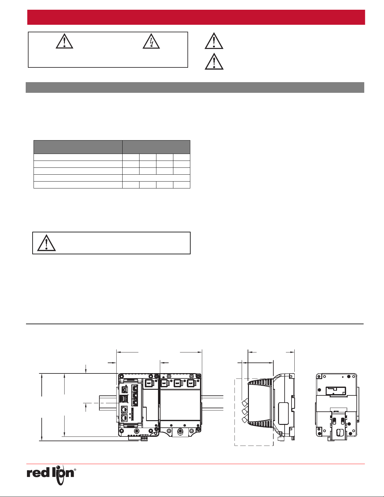
Module sold
separately
2.97 (76)
4.40 (112)
Optional
GEXRACK2
unit
4.11 (104.5)
8.07 (205) *
* +3.96 for each additional base
6.35
(161.4)
2.79
(70.8)
5.95
(151.1)
CAUTION: Risk Of Danger.
Read complete instructions prior to
installation and operation of the unit.
CAUTION: Risk of electric shock.
WARNING - EXPLOSION HAZARD - DO NOT DISCONNECT
EQUIPMENT UNLESS POWER HAS BEEN SWITCHED OFF
OR AREA IS KNOWN TO BE NON-HAZARDOUS.
WARNING - EXPLOSION HAZARD - DO NOT DISCONNECT
EQUIPMENT UNLESS POWER HAS BEEN SWITCHED OFF
OR AREA IS KNOWN TO BE NON-HAZARDOUS.
WARNING - EXPLOSION HAZARD - SUBSTITUTION OF
COMPONENTS MAY IMPAIR SUITABILITY FOR CLASS I,
DIVISION 2.
Drawing No. LP0994
SPECIFICATIONS
1. POWER REQUIREMENTS:
Must use a Class 2 circuit according to National Electrical Code (NEC),
NFPA-70 or Canadian Electrical Code (CEC), Part I, C22.1 or a
Limited Power Supply (LPS) according to IEC 60950-1 or Limitedenergy circuit according to IEC 61010-1.
Power connection via removable three position terminal block.
Supply Voltage: 10-30 VDC
GRAC0001 POWER RATINGS
(WATTS)
Input Voltage 10 V 12 V 24 V 30 V
Typical Power GRAC0001 only: 4 W4 W5 W5 W
Maximum Power GRAC0001 only: 9 W 9 W 10 W 10 W
Available Power for Modules: 55 W
Max Power GRAC0001 With Module(s): 64 W 64 W 65 W 65 W
2. BATTERY: Lithium coin cell. Typical lifetime of 6 years, nominal.
3. MEMORY:
On Board User Memory: 256 Mbyte of non-volatile Flash memory.
Memory Card: SD slot accepts standard capacity cards up to 2 Gbyte.
4. COMMUNICATION CAPABILITIES:
USB Port: Adheres to USB specification 2.0 (high speed, full speed)
only using Type B connection.
USB Host Ports: Comply with Universal Serial Bus Specification Rev
2.0. Support data transfers at (high speed, full speed). Hardware
over current protected (0.5 A max per port).
Serial Ports: Ports are individually isolated. Format and Baud Rates for
each port are individually software programmable up to 115,200
baud.
PGM Port: RS232 port via RJ12.
COMMS Ports: RS422/485 ports via RJ45
DH485 TXEN: Transmit enable; open collector, V
= 0.5 V @ 25 mA max.
V
OL
Port to Port Isolation: 500 Vrms for 1 minute. Signal Isolation: 50 V.
Ethernet Ports: 10 BASE-T / 100 BASE-TX
RJ45 jack is wired as a NIC (Network Interface Card).
Isolation from Ethernet network to GRAC0001: 1500 Vrms
5. ENVIRONMENTAL CONDITIONS:
Operating Temperature Range: -40 to 70 °C, or lowest range among
equipment used in your Graphite system. Consult the user manual
Storage Tempe
Panel Mount Vibration to IEC 68-2-6: Operational 5-500 Hz, 4 g
Panel Mount Shock to IEC 68-2-27: Operational 40 g (10 g, modules w/
relays)
DIN Rail Mount Vibration to IEC 68-2-6: Operational 5-500 Hz, 2 g
DIN Rail Mount Shock to IEC 68-2-27: Operational 15 g (10 g, modules
w/relays)
Requires DIN Rail type: DIN 1010, DIN 1065, or DIN 3065.
Operating and Storage Humidity: 0 to 85% max. RH non-condensing
Altitude: Up to 2000 meters
6. CERTIFICATIONS AND COMPLIANCES:
CE Approved
EN 61326-1 Immunity to Industrial Locations
Emission CISPR 11 Class A
IEC/EN 61010-1
RoHS Compliant
UL Listed: File #E302106
UL Hazardous: File #E317425
7. CONNECTIONS: High compression cage-clamp terminal block
Wire Strip Length: 0.3" (7.5 mm)
Wire Gauge Capacity: One 14 AWG (1.63 mm) solid,
two 18 AWG (1.02 mm) or four 20 AWG (0.81 mm)
8. CONSTRUCTION: Cast aluminum. Installation Category II, Pollution
Degree 2 as defined in IEC 60664-1.
9. WEIGHT: 2 lb 4.2 oz. (1.03 Kg)
rature Range: -40 to 85 °C
= 15 VDC,
OH
DIMENSIONSIninches(mm)
-2-
Page 3

Effective 2017-01-27 Bulletin No. GRAC1-A
2.13 (54)1.72 (43.6)
2.75
(69.8)
5.12
(130)
Captive Screws to fasten
the bases together
1.83 (46.6)
2.13 (54)
Optional GEXRACK2 units
UNLOCK
LOCK
For hazardous location installation, this device is
open type and must be mounted in a suitable ATEX/
IECEx certified tool accessible end-enclosure with a
minimum ingress protection rating of at least IP54 as
defined in EN/IEC 60529 and used in an environment of not
more than Pollution Degree 2 per EN 60664-1. Must be wired
using Division 2 wiring methods as specified in article 501-4
(b), 502-4 (b), and 503-3 (b) of the National Electrical Code,
NFPA 70 for installation within the United States, or as
specified in section 19-152 of Canadian Electrical Code for
installation in Canada.
The protective conductor terminal is bonded to conductive
parts of the equipment for safety purposes and must be
connected to an external protective earthing system.
Drawing No. LP0994
GRAPHITEEDGECONTROLLERINSTALLATION
PANELMOUNTINGINSTRUCTIONS
The Controller can be mounted on a DIN rail for normal environments,
or bolted to a panel for high vibration environments. Refer to the diagram
for the panel mount hole spacing.
DINRAILMOUNTANDCAMOPERATION
It is recommended that the controller be DIN rail mounted only in low
vibration environments. Refer to the Specifications section for details.
1. Using a screwdriver, push in and fully rotate the Cam counter-
clockwise to push the DIN clip downward against spring pressure
locking it open
2. Place the controller on the DIN rail
3. Using a screwdriver, push in and rotate the Cam 90 degrees clockwise
to release the DIN clip to engage the DIN rail
4. Rotate the Cam an additional 90 degrees clockwise to lock the DIN clip
in the closed position.
CONNECTING TO EARTH GROUND
The third pin of the power connector of the Edge Controller is chassis
ground for the unit. Your unit should be connected to earth ground
(protective earth).
The chassis ground is not connected to signal common of the unit.
Maintaining isolation between earth ground and signal common is not
required to operate your unit. But, other equipment connected to this unit
may require isolation between signal common and earth ground. To
maintain isolation between signal common and earth ground care must
be taken when connections are made to the unit. For example, a power
supply with isolation between its signal common and earth ground must
be used. Also, plugging in a USB cable may connect signal common and
earth ground.
1
USB’s shield may be connected to earth ground at the host. USB’s
shield in turn may also be connected to signal common.
1
POWER SUPPLY REQUIREMENTS
The Graphite Edge Controller requires a 10-30 VDC power supply.
Your unit may draw considerably less than the maximum rated power
depending upon the features being used, and the applied voltage. As
additional features are used your unit will draw increasing amounts of
power. Items that could cause increases in current are modules,
additional on-board communications, SD card, and other features
programmed through Crimson software.
Note: Modules connected via a GEXRACK1 to the Edge Controller, are
powered by the GEXRACK1 and not the Edge Controller
To ensure you do not exceed the capacity of your Graphite host power
supply, calculate the total power consumption required for all of your
planned modules. Each module’s maximum power consumption is listed
in the Specifications of their Product Bulletin. The total power available for
modules is listed in the specifications of the Graphite host.
In any case, it is very important that the power supply is mounted
correctly if the unit is to operate reliably. Please take care to observe the
following points:
– Voltage range stated is at the power connector, not at the power source.
– The power supply must be mounted close to the unit, with usually not
more than 6 feet (1.8 m) of cable between the supply and the operator
interface. Ideally, the shortest length possible should be used.
– The wire used to connect the operator interface’s power supply
should be at least 22-gage wire suitably rated for the temperatures
of the environment to which it is being installed. If a longer cable run
is used, a heavier gage wire should be used. The routing of the
cable should be kept away from large contactors, inverters, and
other devices which may generate significant electrical noise.
– A power supply with an NEC Class 2 or Limited Power Source (LPS)
and SELV rating is to be used. This type of power supply provides
isolation to accessible circuits from hazardous voltage levels generated
by a mains power supply due to single faults. SELV is an acronym for
“safety extra-low voltage.” Safety extra-low voltage circuits shall exhibit
voltages safe to touch both under normal operating conditions and after
a single fault, such as a breakdown of a layer of basic insulation or after
the failure of a single component has occurred. A suitable disconnect
device shall be provided by the end user.
– Peak efficiency (GRAC0001) occurs at the low side of the voltage
range (approx. 12 V), recommended for high temperature applications.
EMCINSTALLATIONGUIDELINES
Although Red Lion Controls products are designed with a high degree
of immunity to Electromagnetic Interference (EMI), proper installation and
wiring methods must be followed to ensure compatibility in each
application. The type of the electrical noise, source or coupling method
into a unit may be different for various installations. Cable length, routing,
and shield termination are very important and can mean the difference
between a successful or troublesome installation. Listed are some EMI
-3-
Page 4

Effective 2017-01-27 Bulletin No. GRAC1-A
REMOVE RUBBER
MODULE PLUG
WARNING: Disconnect all power
to the unit before installing or
removing modules.
WARNING - DO NOT CONNECT OR DISCONNECT CABLES
WHILE POWER IS APPLIED UNLESS AREA IS KNOWN TO BE
NON-HAZARDOUS.
Drawing No. LP0994
guidelines for a successful installation in an industrial environment.
1. A unit should be mounted in a metal enclosure, which is properly
connected to protective earth.
2. Use shielded cables for all Signal and Control inputs. The shield
connection should be made as short as possible. The connection point
for the shield depends somewhat upon the application. Listed below
are the recommended methods of connecting the shield, in order of
their effectiveness.
a. Connect the shield to earth ground (protective earth) at one end
where the unit is mounted.
b. Connect the shield to earth ground at both ends of the cable, usually
when the noise source frequency is over 1 MHz.
3. Never run Signal or Control cables in the same conduit or raceway with
AC power lines, conductors, feeding motors, solenoids, SCR controls,
and heaters, etc. The cables should be run through metal conduit that
is properly grounded. This is especially useful in applications where
cable runs are long and portable two-way radios are used in close
proximity or if the installation is near a commercial radio transmitter.
Also, Signal or Control cables within an enclosure should be routed as
far away as possible from contactors, control relays, transformers, and
other noisy components.
4. Long cable runs are more susceptible to EMI pickup than short cable runs.
5. In extremely high EMI environments, the use of external EMI
suppression devices such as Ferrite Suppression Cores for signal and
control cables is effective. The following EMI suppression devices (or
equivalent) are recommended:
Fair-Rite part number 0443167251 (Red Lion Controls #FCOR0000)
Line Filters for input power cables:
Schaffner # FN2010-1/07 (Red Lion Controls #LFIL0000)
6. To protect relay contacts that control inductive loads and to minimize
radiated and conducted noise (EMI), some type of contact protection
network is normally installed across the load, the contacts or both. The
most effective location is across the load.
a. Using a snubber, which is a resistor-capacitor (RC) network or metal
oxide varistor (MOV) across an AC inductive load is very effective at
reducing EMI and increasing relay contact life.
b. If a DC inductive load (such as a DC relay coil) is controlled by a
transistor switch, care must be taken not to exceed the breakdown
voltage of the transistor when the load is switched. One of the most
effective ways is to place a diode across the inductive load. Most
Red Lion products with solid state outputs have internal zener diode
protection. However external diode protection at the load is always a
good design practice to limit EMI. Although the use of a snubber or
varistor could be used.
Red Lion part numbers: Snubber: SNUB0000
Varistor: ILS11500 or ILS23000
7. Care should be taken when connecting input and output devices to the
instrument. When a separate input and output common is provided,
they should not be mixed. Therefore a sensor common should NOT be
connected to an output common. This would cause EMI on the
sensitive input common, which could affect the instrument’s operation.
8. For GEXRACK1 connection, recommend Tripp Lite Model: U023-006 6
ft cable.
I/OMODULEINSTALLATION
The physical order of all installed modules must match the modules
order as set in Crimson database. Torque screws to 6.0 pound-force inch
[96 ounce-force inch] (0.68 Nm).
COMMUNICATINGWITHTHECONTROLLER
CONFIGURINGANEDGECONTROLLER
The Controller is configured using Crimson® software. Crimson
software is available as a no charge download from Red Lion’s website.
Crimson updates for new features and drivers are posted on the website
as they become available. By configuring the Edge Controller using the
latest Crimson version, you are assured that your unit has the most up to
date feature set. Crimson software can configure the controller through
the RS232 PGM port, USB port, ethernet port or SD card.
The USB port is connected using a standard USB cable with a Type B
connector. The driver needed to use the USB port will be installed as part
of Crimson configuration.
The RS232 PGM port uses a programming cable made by Red Lion to
connect to the DB9 COM port of your computer. If you choose to make
your own cable, use the “Graphite Edge Controller Port Pin Out Diagram”
for wiring information.
The SD card can be used to program a controller by placing a
configuration file and firmware on the SD card. The card is then inserted
into the target controller and powered. Refer to the Crimson literature for
more information on the proper names and locations of the files.
SYSTEM LEDs
COLOR STATUS
GREEN (STS) Bootloader/Power
GREEN (SD) File system SD Card
USB HOST LEDs
COLOR STATUS
OFF Not operational
RED Error
GREEN Normal operation
USB,DA TATRANSFERSFROMTHESDCARD
In order to transfer data from the SD card via the USB port, a driver
must be installed on your computer. This driver is installed with Crimson
software and is located in the folder C:\Program Files\Red Lion
Controls\Crimson 3.0\Device\ after installation. This may have already
been accomplished if your controller was configured using the USB port.
Once the driver is installed, connect the controller to your PC with a
USB cable, and follow “Mounting the SD” instructions in the Crimson 3.0
user manual.
-4-
Page 5

Effective 2017-01-27 Bulletin No. GRAC1-A
TX
5V
8
1
7
2
TxB
TxA
130K
130K
5
RX
130K
5V
130K
RxB
4
RxA
3
COMM
6
RS422/485 4-WIRE
CONNECTIONS
RS485 2-WIRE
CONNECTIONS
TX/RX
130K
5
TxA
2
8
130K
5V
7
1
TxB
6 COMM
Drawing No. LP0994
INSERTION/REMOVALOFTHESDCARD
Insert the SD card into the slot provided with the card oriented as shown.
The card is inserted properly when the end of the card is flush with the
Edge Controller case. To remove the SD card, push in slightly on the card.
Warning: Do not remove the SD card while power is applied.
CABLESANDDRIVERS
Red Lion has a wide range of cables and drivers for use with many
different communication types. A list of these drivers and cables along
with pin outs is available from Red Lion’s website. New cables and
drivers are added on a regular basis. If making your own cable, refer to
the “Port Pin Outs” that corresponds to your specific model for wiring
information.
ETHERNETCOMMUNICATIONS
Ethernet communications can be established at either 10 BASE-T or
100 BASE-TX. The Graphite unit’s RJ45 jack is wired as a NIC (Network
Interface Card). Ports support Auto MDI-X (which automatically detects
and configures the cable connection).
The Ethernet connector contains two LEDs. A yellow LED in the upper
right, and a green LED in the upper left. The LEDs represent the following
statuses:
LED COLOR DESCRIPTION
YELLOW solid Link established.
YELLOW flashing Data being transferred.
GREEN (OFF) 10 BASE-T Communications
GREEN (ON) 100 BASE-TX Communications
A 12-digit MAC address label is provided for each Ethernet port. Refer
to the Crimson manual and Red Lion’s website for additional information
on Ethernet communications.
RS232PORTS
The Edge Controller has a
single RS232 port. The port can
be used for either master or
slave protocols with any
Graphite configuration.
GRAPHITE RS232 TO A PC
Gxx:
RJ12
Name
4 COMM 1 DCD
5Tx2Rx
2Rx3Tx
N/C 4 DTR
3COMM5GND
N/C 6 DSR
1CTS7RTS
6RTS8CTS
N/C 9 RI
PC:
DB9
Name
RS422/485COMMSPORT
The controller has two RS422/485 ports. These ports can be
configured to act as either RS422 or RS485.
TxEN (OC)
Note: All Red Lion devices connect A to A and B to B.
ExamplesofRS4852‐WireConnections
GRAPHITE TO RED LION RJ11
Gxx:RJ45 Name RLC:RJ11 Name
5TxEN2 TxEN
6COMM3COMM
1TxB5 B-
2TxA4 A+
DH485COMMUNICATIONS
The Graphite Edge Controller’s RS422/485 COMMS port can also be
used for Allen Bradley DH485 communications.
GRAPHITE TO AB SLC 500
RJ45: RLC Name RJ45: A-B Name
1TxB1 A
2TxA2 B
3, 8 RxA - 24V
4, 7 RxB - COMM
5TxEN5TxEN
6COMM4SHIELD
4, 7 TxB - COMM
3, 8 TxA - 24V
-5-
TxEN (OC)
Page 6

Effective 2017-01-27 Bulletin No. GRAC1-A
USB
TYPE B
PORT B
USB HOST
PORT A
ETHERNET 1
(NIC)
ETHERNET 2
(NIC)
STATUS
STATUS
STATUS LED
RS232
PGM PORT
RTS (PIN 6)
COMM
COMM
CTS (PIN 1)
Tx
Rx
RS485 - A
COMMS PORT
TxA (PIN 8)
TxB (PIN 1)
COMM
RxB
TxB
TxEN
TxA
RxA
TxA (PIN 8)
COMMS PORT
RS485 - B
RxB
TxB (PIN 1)
TxA
RxA
COMM
TxB
TxEN
SD STATUS LED
FACTORY RESET BUTTON
POWER
CONNECTOR
+DC VOLTAGE
COMMON1CHASSIS
2
3
GRAPHITE EDGE CONTROLLER PORT PIN OUTS
WARNING - EXPLOSION HAZARD - DISCONNECT POWER AND
ENSURE THE AREAS IS KNOWN TO BE NON-HAZARDOUS
BEFORE SERVICING/REPLACING THE UNIT AND BEFORE
INSTALLING OR REMOVING I/O WIRING AND BATTERY.
Remove 4 Torx
T10 screws
Drawing No. LP0994
SOFTWARE/UNITOPERATION
CRIMSON
Crimson software is available as a no charge download from Red
Lion’s website. The latest version of the software is always available from
the website, and updating your copy is free.
FACTORYRESETBUTTON
The factory reset button is located on the front of the unit.
GRAPHITETROUBLESHOOTING
If for any reason you have trouble operating, connecting, or simply
have questions concerning your new Graphite unit, contact Red Lion’s
technical support.
BATTERY&TIMEKEEPING
A battery is used to keep time when the unit is without power. Typical
accuracy (at 25°C) of the time keeping is less than one minute per month
drift. This battery does not affect the unit’s memory, all configurations and
data is stored in non-volatile memory.
®
SOFTWARE
ChangingtheBattery
To change the battery, first remove power to the unit. Remove all
cables from the unit and any external module if installed. Remove the four
TORX screws holding the metal cover to the unit, two per side. Slide the
metal cover forward to gain access to the battery. Remove the old
battery* from the holder and replace with the new battery. Replace metal
cover with the four TORX screws. Reinstall external module if equipped,
reconnect cables and re-apply power. Using Crimson software, enter the
correct time and date.
* Please note that the old battery must be disposed of in a manner that
complies with your local waste regulations. The battery must not be
disposed of in fire, or in a manner whereby it may be damaged and its
contents could come into contact with human skin.
The battery used by the Graphite Edge Controller is an industrial
temperature grade (-40°C, 85°C) lithium type BR2032.
-6-
 Loading...