

Page 1

THE ASTRO LINE SERIES
GEMINI 5200 INSTRUCTION MANUAL
Page 2

INTRODUCTION
The Gemini 5200 is another unit in a multi-purpose series of industrial
control products that are field-programmable to solve multiple applications.
This series, known as the Astro-Line family of products, is built around the
concept that the end user has the capability to program different
personalities and functions into the unit in order to adapt to different
indication and control requirements.
The Gemini 5200, which you have purchased, has the same high quality
workmanship and advanced technological capabilities that have made Red
Lion Controls the leader in today's industrial market.
Red Lion Controls has a complete line of industrial indication and control
equipment, and we look forward to being of service to you now and in the
future.
CAUTION: Read complete instructions prior
to installation and operation of the unit.
CAUTION: Risk of electric shock.
Page 3

TABLE OF CONTENTS
I. GENERAL DESCRIPTION 2
A) Safety Summary
B) Programming The Gemini 5200
C) Programming The Personality
D) Programming The Presets, Scale Factors, Timed Output Values
E) Factory Settings
F) Operator Accessible Functions With Programming Disabled
G) Diagnostics, Self-Test, & “Watchdog” Timer
H) Input Circuitry & Set-up
I) Overflow Indication
II. PROGRAMMING THE GEMINI 5200 IN DUAL RATE WITHOUT DISPLAY C MODE
A) Codes 41, 42, 43, 44, 45, & 46
B) Codes 51, 52, 53, 54, 55, & 56
C) Codes 61, 62, 63, 64, 65, 66, Preset Values, & Scale FactorsA&B
III. PROGRAMMING THE A/B, (A-B)/B, & A-B DISPLAY C MODES
A) Basic Operation
B) Codes 41, 42, 43, 45, & 46
C) Codes 51, 52, 53, 54, & 55
D) Codes 61, 62, 63, 64, 65, 66, Preset Values, & Scale FactorsA&B
E) Gemini 5200 Programming Example - Speed Ratio Application
IV. GEMINI 5200 20 MA CURRENT LOOP COMMUNICATIONS
A) Communication Format
B) Sending Commands & Data To The Gemini 5200
C) Receiving Data From The Gemini 5200
D) Print Options
E) Current Loop Installation
F) Communications Application
G) Troubleshooting Gemini Serial Communications & Serial Loop-Back Self-Test
V. APPENDIX “A” - INSTALLATION & INPUT CONFIGURATION SWITCH SET-UP
VI. APPENDIX “B” - SPECIFICATIONS & DIMENSIONS
VII. APPENDIX “C” - TROUBLESHOOTING GUIDE
VIII. APPENDIX “D” - DUAL RATE W/O DISP C FUNCTION COMMAND CODE SUMMARY
IX. APPENDIX “E” - GEMINI 5200 DUAL RATE W/DISP C FUNCTION COMMAND CODE SUMMARY
X. APPENDIX “F” - SCALING FOR RATE & DISPLAY C
XI. APPENDIX “G” - GEMINI 5200 PROGRAMMING CHARTS
XII. APPENDIX “H” - ORDERING INFORMATION
3-4
5-6
9-10
10-12
12-14
15-16
16-18
18-20
21-22
24-25
30-37
38-39
40-41
42-45
46-49
50-52
53-56
2
2
2
7
7
8
8
9
15
15
23
23
26
26
27
28
29
57
-1-
Page 4

GENERAL DESCRIPTION
The Gemini 5200 is a multi-function dual rate indicator which can fulfill
almost any rate indication application. The unit can operate as two independent
rate indicators, with scaling, decimal point placement, and update times,
separately programmable for each channel. TheGemini5200alsohas three other
unit personalities. These modes feature a third display channel, C, which can
indicate the ratio, difference or draw between the A and B rate channels.
The programming of the rate channels and the calculated display is very
straightforward. Setting up Channel C only requires programming the desired
amount of resolution (for ratio and draw) and the appropriate decimal point
location. The Gemini 5200 simply takes the two rate values and mathematically
calculates display C accordingly.
The Gemini 5200 20 mA Current Loop Communications option provides the
capability of two-way serial communications between the Gemini 5200 and a
variety of equipment, such as a printer, remote terminal, programmable
controller, or host computer. The baud rate can be set to 300, 600, 1200, or 2400
baud. The format for transmitted and received data is 1 start bit, 7 data bits, 1
parity bit (odd), andastopbit.Whenutilizinganexternalpowersupply(30VDC
max.), up to sixteen units can be installed in the loop, each with an individual
address. When utilizing the Gemini’s20mAcurrentsource, up to seven unitscan
be installed in a loop. The Rate Values, Presets, and Scale Factor can be
interrogated or changed by sending the proper command codes and numerical
data (if required) to the unit. Various “Print Options” can be selected to
automatically interrogate the Rate Values, Presets, and Scale Factor by
activating the “Print Request” terminal or by sending a “Transmit Per Print
Option” (P) command.
The construction of the Gemini 5200 features a metal die-cast bezel, offering
maximum durability with a high quality die-cast appearance. The sealed front
panel meets NEMA 4/IP65 specifications for washdown and/or dust when
properly installed. Clamp type pressure plate terminals accept stripped #14
AWG wire without lugs.
SAFETY SUMMARY
All safety related regulations, local codes and instructions that appear in the
manual or on equipment must be observed to ensure personal safety and to
prevent damage to either the instrument or equipment connected to it. If
equipment is used in a manner not specified by the manufacturer, the protection
provided by the equipment may be impaired.
Do notusethisunittodirectly command motors, valves, or other actuators not
equipped with safeguards. To do so, can be potentially harmful to persons or
equipment in the event of a fault to the unit.
PROGRAMMING THE GEMINI 5200
When your Gemini 5200 arrives from the factory, it has already been
programmed to function as a Dual Rate Indicator without the calculated C
display. It is programmed with the factory settings listed in the “Factory
Settings” section. If it is required to have the unit operate as a speed ratio, speed
difference or draw indicator, the Unit Personality function code can be changed
to do so.
The personality, functions, and modes are accessed by pressing the
appropriate keys as indicated by the embossed numbers above them. A function
is defined by a two-digit code which appears on the left side of the display. The
mode of that function is shown as a one-digit code on the right side of the display.
At times there will be a “-” sign modifier to the left of the mode.
Data for the Presets, Scale Factors and Timed Output Values are entered
differently. Each digit key controls the digit on the display directly above it.
Changing the digits can be done by repeatedly pressing the key beneath the digit
position you wish to changeor by holding the key down. As you hold it down,or
repetitively press it, the value of that digit will change cyclically, counting up to
9, then to 0, and thenup again. The 6 numbered keys correspond to thesix digits,
and the “+/-” key corresponds to polarity.
PROGRAMMING THE PERSONALITY
Entering function and mode is easily accomplished by
pressing the appropriate digit key. For the personality
function, you would enter 41 by pressing the front panel
keys, 4 and 1.
The digitsontheleftside of the display show the function
code; the digits on the right side show the current
programmed mode.
A newmode selection is made by enteringanew number.
On some of the entries, you have the option of a plus “+” or
minus “-” sign. In the cases where a “+” sign is required, no
sign will be displayed. If you do enter a “-” sign (using the
“+/-” key), a minus sign will be displayed in front of the
appropriate digit.
-2-
Page 5

Pressing the “E” key finalizes the change. The display
will now show the rate value immediately.
If you do not press the “E” key, the change will not be
recorded. The displaywillremainintheprogrammingmode
for 15 seconds, and then return to normal operating mode
using the old function and mode settings.
Whenever the Unit Personality is changed, the factory settings will
automatically be loaded into the unit. The factory settings can also be
programmed into theunitbycallinguptheUnitPersonality,puttinga “-” in front
of the mode by pushing the “+/-” key, and entering it.
Refer to the “Initial Factory Configuration” section for more details.
PROGRAMMING THE PRESETS, SCALE FACTORS &
TIMED OUTPUT VALUES
The Presets and Scale Factor Values are commonly reprogrammed on a daily
basis. As such, single keystroke access has been provided on the front panel.
The Gemini 5200 has two Scale Factors, one for Rate
Display A,and one for Rate Display B. Pressing the “3”key
will call up the Scale Factor for the current rate value being
displayed (Rate A or Rate B).
To call up the “other” Scale Factor, the “+/-” key is first pushed to change the
display to the “other” value (Rate A or Rate B), then the “3” key is pushed to
display the Scale Factor for that value.
The internal unscaled rate valueismultipliedbythe Scale Factor Value,which
changes the displayed value accordingly.
To display the Preset 1 Value, the “1” key is pushed.
To change the value, the digits can be cycled through in
the same manner as discussed for the Scale Factors. The
Preset Values can range from -999999 to +999999.
The new valuewillbeentered when the“E”keyis pressed.
The Timed Output Values are changed by entering
two-digit function codes. After the code is entered, the
display will show the present Timed Output 1 or 2 Value in
seconds with two decimal place resolution. The Timed
Output Values can be set from .01 to 599.99 seconds.
Once the Scale Factor is displayed, changing the digits
can beaccomplished by repeatedly pressing the key beneath
the digit position you wish to change or by holding the key
down, allowing the digit to cycle.
The new valuewillbeentered when the“E”keyis pressed.
To changetheTimedOutput 1 Value, enter function code
53 and enter the new value by holding down or repeatedly
pressing the keybelowthedigit position youwishto change.
The newvalue willbe entered when the “E” key is pressed.
The display will immediately return to the rate value.
-3-
Page 6

PROGRAMMING THE PRESETS, SCALE FACTORS &
TIMED OUTPUT VALUES [Cont’d]
Note: A Timed Output Value of zero cannot be programmed into the Gemini
5200. Ifa value of 0 is entered into the display, and the “E”key is pressed, the
unit will remain in data entry mode. If a new value is not entered, it will time
out and the unit will continue to use its previous setting.
As with the other functions, you must press “E” to record the changes. For the
data entry modes, if you do not press the“E” key, a time out of 5 seconds occurs,
and the display returns to operating mode without any changes to the value. The
only time any change will occur is when the “E” key is pressed.
-4-
Page 7
FACTORY SETTINGS
INITIAL FACTORY CONFIGURATION (DUAL RATE)
Keys Struck Display Description
4,1 41 1 Personality selected as DUAL RATE W/O DISP C
4,2 42 3 Reset RateA&Boutputs
4,3 43 1 Rate B Conversion Factor is Rate Per Second (x1)
4,4 44 1 Rate B Minimum Update time of 0.5 Sec.
4,5 45 4 Rate B Scale Multiplier of 1.0
4,6 46 1 Rate B leading zero blanking and no decimal point
5,1 51 1 Output 1 assigned to Rate A, Output 2 to Rate B
5,2 52 3 Output 1 terminates at Reset, Normal Phase
5,3 0000.10 Timed Output 1 value of 0.1 Sec.
5,4 54 3 Output 2 terminates at Reset, Normal Phase
5,5 0000.10 Timed Output 2 value of 0.1 Sec.
5,6 56 4 No Rate B right hand dummy zeros
6,1 61 4 No Rate A right hand dummy zeros
6,2 62 1 Rate A Conversion Factor is Rate per Second (x1)
6,3 63 1 Rate A Minimum Update Time of 0.5 Sec.
6,4 64 4 Rate A Scale Multiplier of 1
6,5 65 1 Rate A leading zero blanking, no decimal point
6,6 66 1 No functions except Reset enabled
3 01.0000 Scale Factor A (Rate A) set to 1.0000
3 01.0000 Scale Factor B (Rate B) set to 1.0000
1 000500 Preset 1 set to 500
2 001000 Preset 2 set to 1000
DUAL RATE WITH SPEED RATIO FACTORY SETTINGS *
Keys Struck Display Description
4,1 41 2 Personality selected as DUAL RATE W/SPEED RATIO
4,2 42 3 Reset RateA&Boutputs
4,3 43 1 Rate B Conversion Factor is Rate Per Second (x1)
4,5 45 4 Rate B Scale Multiplier of 1.0
4,6 46 1 Display C leading zero blanking and no decimal point
5,1 51 1 Output 1 assigned to Rate A, Output 2 to Rate B
5,2 52 3 Output 1 terminates at Reset, Normal Phase
5,3 0000.10 Timed Output 1 value of 0.1 Sec.
5,4 54 3 Output 2 terminates at Reset, Normal Phase
5,5 0000.10 Timed Output 2 value of 0.1 Sec.
6,1 61 1 Display C Multiplier of 1
6,2 62 1 Rate A Conversion Factor is Rate per Second (x1)
6,3 63 1 Rate Minimum Update Time of 0.5 Sec.
6,4 64 4 Rate A Scale Multiplier of 1
6,5 65 1 RateA&Bleading zero blanking, no decimal point
6,6 66 1 No functions except Reset enabled
3 01.0000 Scale Factor A (Rate A) set to 1.0000
3 01.0000 Scale Factor B (Rate B) set to 1.0000
1 000500 Preset 1 set to 500
2 001000 Preset 2 set to 1000
* If function Code 41 is changed to [41 2], then the factory settings are as shown.
-5-
Page 8

FACTORY SETTINGS [Cont’d]
DUAL RATE WITH SPEED DIFF. FACTORY SETTINGS *
Keys Struck Display Description
4,1 41 3 Personality selected as DUAL RATE W/SPEED DIFF.
4,2 42 3 Reset RateA&Boutputs
4,3 43 1 Rate B Conversion Factor is Rate Per Second (x1)
4,5 45 4 Rate B Scale Multiplier of 1.0
4,6 46 1 Display C leading zero blanking and no decimal point
5,1 51 1 Output 1 assigned to Rate A, Output 2 to Rate B
5,2 52 3 Output 1 terminates at Reset, Normal Phase
5,3 0000.10 Timed Output 1 value of 0.1 Sec.
5,4 54 3 Output 2 terminates at Reset, Normal Phase
5,5 0000.10 Timed Output 2 value of 0.1 Sec.
6,2 62 1 Rate A Conversion Factor is Rate per Second (x1)
6,3 63 1 Rate Minimum Update Time of 0.5 Sec.
6,4 64 4 Rate A Scale Multiplier of 1
6,5 65 1 RateA&Bleading zero blanking, no decimal point
6,6 66 1 No functions except Reset enabled
3 01.0000 Scale Factor A (Rate A) set to 1.0000
3 01.0000 Scale Factor B (Rate B) set to 1.0000
1 000500 Preset 1 set to 500
2 001000 Preset 2 set to 1000
* If [41 1] is changed to [41 2], then the factory settings are as shown.
DUAL RATE WITH SPEED DRAW FACTORY SETTINGS *
Keys Struck Display Description
4,1 41 4 Personality selected as DUAL RATE W/SPEED DRAW
4,2 42 3 Reset RateA&Boutputs
4,3 43 1 Rate B Conversion Factor is Rate Per Second (x1)
4,5 45 4 Rate B Scale Multiplier of 1.0
4,6 46 1 Display C leading zero blanking and no decimal point
5,1 51 1 Output 1 assigned to Rate A, Output 2 to Rate B
5,2 52 3 Output 1 terminates at Reset, Normal Phase
5,3 0000.10 Timed Output 1 value of 0.1 Sec.
5,4 54 3 Output 2 terminates at Reset, Normal Phase
5,5 0000.10 Timed Output 2 value of 0.1 Sec.
6,1 61 1 Display C Multiplier of 1
6,2 62 1 Rate A Conversion Factor is Rate per Second (x1)
6,3 63 1 Rate Minimum Update Time of 0.5 Sec.
6,4 64 4 Rate A Scale Multiplier of 1
6,5 65 1 RateA&Bleading zero blanking, no decimal point
6,6 66 1 No functions except Reset enabled
3 01.0000 Scale Factor A (Rate A) set to 1.0000
3 01.0000 Scale Factor B (Rate B) set to 1.0000
1 000500 Preset 1 set to 500
2 001000 Preset 2 set to 1000
* If [41 1] is changed to [41 2], then the factory settings are as shown.
-6-
Page 9

OPERATOR ACCESSIBLE FUNCTIONS WITH
PROGRAMMING DISABLED
One of the important features of the Gemini 5200 is the ability to disable
programming. With this ability, accidental bumping of the keys or tampering by
unauthorized personnel canbe prevented.However, itmay benecessary toallow
reset and certain programming functions, such as Presets and Scale Factor
Values, to be changed indaily operation. The Gemini5200, through the use ofthe
“Operator Accessible Functions” modes, can enable these functions even when
the “PGM. DIS.” terminal is connected to “COMMON”.
The “Operator Accessible Functions” modes are programmed by entering a
two-digit function code (66) and the desired mode. Unlike other function codes,
the mode does not take effect immediately. The “PGM. DIS.” terminal must be
connected to “COMMON” in order for the Gemini to disable programming and
operate as per the mode programmed.
There are four basic “Operator Accessible Functions” Modes available. These
modes enable the following functions.
1. NO FUNCTIONS EXCEPT RESET ENABLED - In this mode, manual
reset is enabled, but none of the programming functions can be changed.
However, the functions can be interrogated.
2. PRESET PROGRAMMING AND RESET ENABLED - The entire front
panel is disabled with the exceptions of Preset programmability and manual
reset. All functions can be interrogated.
3. SCALE FACTOR PROGRAMMING AND RESET ENABLED - The
entire front panel is disabled with the exceptions of Scale Factor
programmability and manual reset. All functions can be interrogated.
4. SCALE FACTOR AND PRESET PROGRAMMING, AND RESET
ENABLED - The entire front panel is disabled with the exceptions of Scale
Factor and Preset programmability, and manual reset. All functions can be
interrogated.
All of these modes can be modified with the addition of a “-” sign. The minus
sign disables the manual reset, at the front panel and the remote reset (RST., not
RST.A) terminal, at the rear of the unit.
There is also a rear panel DIP switch which permits disabling of the front panel
reset button. This is independentof the rear terminal remote reset, and canbe used in
conjunction with any front panel disable mode. The combination of a manual and
remote reset inputs provides a high level of security without sacrificing flexibility.
DIAGNOSTICS, SELF-TEST, & “WATCHDOG” TIMER
The security of the Gemini5200 is further enhanced by its self-test diagnostic
and “watchdog” timer capabilities.
The diagnostics are concerned with the special, no power memory of the
Gemini 5200. Whenever the power is turned off, all pertinent function settings
and measurements are automatically saved. When power is restored, the
functions and data are re-instated. This allows you to program the unit once and
not have to re-program it until you wish to use it in another mode.
When the function codes and data are saved, computations are made with
these values.The resultof these computations is stored in the memory to serve as
a check against possible error. On powerup, the same computations are repeated
on the stored data. If the results do not agree with the stored results, a “P” will
appear onthe left side of thedisplay. If this occurs, refer to the “Troubleshooting
Guide” for directions.
The Gemini 5200 also contains a “watchdog” timer. In order to insure the
software is functioning properly, the program constantly monitors itself. If the
proper sequence and timing of internal events does not occur, an “E” will appear
on the left side of the display. If this occurs, refer tothe “Troubleshooting Guide”
for directions.
The final type of built-in check, is the front panel initiated self-test. It can be
performed at any time, even when the Gemini 5200 is running. It will not
interfere with the accumulation ofcounts orcontrol functions. A function codeof
“6”, “+/-” starts the test.At this time, whatever was displayed will disappear and
be replaced by a string of decimal points and the overflow indicator. Then the
display willshow a string of 9’s, then 8’setc., until a string of 0’s areshown. The
self-test will then turn off the overflow indicator and activate the minus “-” sign.
Then the unit shows an interlace pattern of -010101, then -212121, followed by
-232323 etc., until -898989 is reached. At this time the outputs can be tested by
pressing the “1” or “2” key. (The program disable pin must be disconnected in
order to allow activation of the outputs.) An automatic exit will take place after
six seconds or immediately if the Program Disable terminal is connected to
common. Normallength ofdisplay timefor eachof the patterns is approximately
0.5 sec. Rapidly pressing “E” during self-test can speed up the sequence.
-7-
Page 10

INPUT CIRCUITRY & SET-UP
There are two independent input channels on the Gemini 5200. Various types
of sensoroutputs can be accommodated by appropriate DIP switch set-up.These
include: TTL or CMOS logic, current sinking, current sourcing, dry contact or
magnetic pickup.
Both Input Channels A and B consist of a logic input and a separate low level
magnetic pickup input. For a complete detailed description of input set-up, see
Appendix “A”.
OVERFLOW INDICATION
The Gemini5200 features anoverflow indicator (LED)which is locatedto the left
of the sixth digit and above the polarity annunciator. This LED will turn on if the
capacity of the display (6-digits) is exceeded or if the following conditions occur.
Upon power-up, the display willgo to zero, andthe overflow LED will turnon.
The overflow LED is turned on to indicate that the zero on the display is not a
measured value. The overflow LED will turn off after the Gemini 5200
completes its rate measurement. It will take 16 seconds if the rate is zero.
The overflow LED can also turn on when the rate input frequency exceeds the
maximum 3250 cps allowed for a rate update period of 16 sec. See Code 63 “Rate Minimum Update Time”.
-8-
Page 11

PROGRAMMING THE GEMINI 5200 IN DUAL RATE WITHOUT DISPLAY C MODE
The rate indicators use a time interval method (1/tau) to calculate the rate
value. This method enables high resolution at all input rates. The unit counts
input pulses and after a programmable minimum update time has occurred, it
waits until the next count edge occurs, takes the elapsed time and number of
edges, and calculates the rate value. At slower rates, averaging can be
accomplished by programming the “Minimum Update Time”(0.5 sec.to 16 sec.)
for the desired response. Extensive scaling capabilities allow practically any
desired reading at very slow count rates.
In the Dual Rate, without Display Cmode, thetwo rateindicators operate in an
independent non-synchronized fashion. Input A serves as the inputto the Rate A
indicator and Input B serves as the input to the Rate B indicator. All modes are
independently selected for each rate channel.
CODE 41 - UNIT PERSONALITY
The unit personality mode is the first function code that is programmed. This
mode will determine the basic operational characteristics of the unit. This
programming section deals with the unit programmed as a Dual Rate Indicator
without Display C, mode 1. The “Programming The A/B, (A-B)/B, And A-B
Display C Modes” section covers programming of the Gemini 5200 whenin Unit
Personality modes 2, 3, and 4.
Once the Unit Personality mode is changed, the factory settings will
automatically be loaded into the unit’s memory. This provides a known starting
place. If at any point, it is desired to return to the factory settings for the current
mode, the unit personality is called up, a minus is put in front of the mode by
pressing the“+/-” key, and the “E” key is pushedto load the factory settings. The
factory settings are listed on page 5 and 6.
[41 1] DUAL RATE INDICATION - In this mode, the Gemini 5200 operates as
two independent rate indicators.
[41 2] DUAL RATE WITH A/B DISPLAYC-Inthis unit personality, the
Gemini 5200 operates as a dual rate indicator with an A/B display C function.
See “Programming The A/B, (A-B)/B,And A-B Display CModes” section for
programming details.
[41 3] DUAL RATE WITH A-B DISPLAYC-Inthis unit personality, the
Gemini 5200 operates as a dual rate indicator with an (A-B) Display C
function. See “Programming The A/B, (A-B)/B, And A-B Display C Modes”
section for programming details.
[41 4] DUAL RATE WITH (A-B)/B DISPLAYC-Inthis unit personality, the
Gemini 5200 operates as a dual rate indicator with an (A-B)/B Display C
function. See “Programming The A/B, (A-B)/B, And A-B Display C Modes”
section for programming details.
[41 -1]
[41 -2] A minus indicator preceding the mode will cause
[41 -3] the factory settings to be loaded when entered.
[41 -4]
CODE 42 - RESET KEY & TERMINAL ACTUATION MODES
The Reset Button & Terminal Actuation Modes controls the effect that the
reset button and terminal have on the two display channels. Resetting will not
affect the rate displays or update period in any manner. Reset only affects the
output(s) associated with the rate channels.
There is a separate “Rst A” terminal provided which makes it possible to
independently reset both the Rate A and B Outputs.
[42 1] RESET RATE A OUTPUT(S)
[42 2] RESET RATE B OUTPUT(S)
[42 3] RESET RATEA&BOUTPUTS
CODE 43 - RATE B CONVERSION FACTOR
The Rate B Conversion Factor is used to convert Display B to indicate rate in
the desired time unit. See Appendix “F” - Scaling For Rate And Display C.
[43 1] Rate Per Second (x1)
[43 2] Rate Per Minute (x60)
[43 3] Rate Per Hour (x3600)
-9-
Page 12

CODE 44 - RATE B MINIMUM/MAXIMUM UPDATE TIME
The determination of the rate value usesa method in which theelapsed time is
measured between the first and last pulse of the update period. The minimum
update time is the shortest the time period can be. Once the minimumupdate time
has expired, the unit will end the measurement period when the next negative
going count edgeoccurs. Ifthe unitdoes notreceive thenext negative count edge
within the maximum update time at the start of the measurement period, the unit
will end the time period and the rate display will go to zero. At very slow count
rates the update time period will be the actual period of one count cycle.
[44 1] 0.5 Sec. minimum/1 Sec. maximum
[44 2] 1 Sec. minimum/2 Secs. maximum
[44 3] 2 Secs. minimum/4 Secs. maximum
[44 4] 4 Secs. minimum/8 Secs. maximum
[44 5] 8 Secs. minimum/16 Secs. maximum (max. rate = 7500 cps)
[44 6] 16 Secs. minimum/32 Secs. maximum (max. rate = 3250 cps)
CODE 45 - RATE B SCALE MULTIPLIER
The Rate B Scale Multiplier is used in conjunction with the Rate Scale Factor
B and Rate B Conversion Factor to scale the actual signal input to obtain the
desired reading.
[45 1] x 1000
[45 2] x 100
[45 3] x10
[45 4] x1
[45 5] x 0.1
[45 6] x 0.01
CODE 46 - RATE B DECIMAL POINT & LEADING ZERO
BLANKING
There are six basic modes of decimal point placementfor the Rate B indicator
of the Gemini 5200. The decimal point is placed to the right of the display digit
that corresponds to the mode identifier. (The right most decimal point, digit 1, is
never turned on.) A “-” sign in front of the mode identifier will inhibit leading
zero blanking. The absence of a “-” sign will enable leading zero blanking.
[46 1] 0
[46 2] 0.0
[46 3] 0.0 0 LEADING ZERO
[46 4] 0.0 0 0 BLANKING
[46 5] 0.0000
[46 6] 0.00000
[46 -1] 000000
[46 -2] 00000.0
[46 -3] 0 0 0 0.0 0 LEADING ZERO
[46 -4] 0 0 0.0 0 0 BLANKING INHIBITED
[46 -5] 00.0000
[46 -6] 0.00000
CODE 51 - OUTPUT ASSIGNMENT
The outputs of the Gemini 5200 can be assigned to either the Rate A or Rate B
channel or one to each.
The Gemini 5200 has a Preset tracking feature which allows Preset 1 to track
Preset 2.If Presettracking isprogrammed, wheneverthe Preset2 valueis changed,
the Preset 1 value will also change to maintain the same offset. For example, if
Preset 1 is 100 and Preset 2 is 200, changing Preset 2 to 300 will automatically
change Preset1 to200, maintainingthe same100 unitoffset. Inorder to change the
amount of offset, the Preset 1 value is changed. The Preset tracking feature is
programmed by adding a “-” modifier in front of the desired mode.
Note: When Preset tracking is enabled, before changing Preset 2 via serial
communications, the Preset 2 value must be interrogated in order to establish
the Preset 1 value.
[51 1] Output 1 assigned to Rate A, Output 2 assigned to Rate B
[51 2] Outputs1&2assigned to Rate B
[51 3] Outputs1&2assigned to Rate A
[51 -1]
[51 -2]
[51 -3]
These modes are the same as above with the exception
that Preset Tracking is enabled.
-10-
Page 13

CODE 52 - OUTPUT 1 TERMINATION MODES
The Gemini 5200 has four “Output 1 termination Modes” which control the
way Output 1 will terminate or reset. In all modes, Output 1 will terminate
immediately when the channel to which it is assigned is manually reset.
A reverse phase mode is available on the Gemini 5200. This refers to the
complementing of the logic state of Output 1. With normal phase operation,
when the display value reaches Preset 1, Output 1 will turn on. The reset
condition ofOutput 1 is output off. In reversephase operation, Output 1 turns off
when Preset 1 is reached. The reset condition of Output 1 is output on. (Note: The
state of the relay, if used, is also reversed.) A “-” sign in front of the mode
identifier will provide for reverse phase operation. The absence of a “-” sign will
indicate normal phase operation.
[52 3] TERMINATE AT MANUALRESET -Output 1 activates whenthe rateis
greater than or equal to the Preset 1 value. In this mode, once Output 1 is
activated, it does not deactivate until the moment a manual reset occurs.
Output 1 is set for normal phase operation.
[52 4] TERMINATE AT MANUAL RESET END - This mode is like the
preceding, except Output 1 deactivates when reset ends. Output 1 is set for
normal phase operation.
[52 5] TERMINATE AFTER TIMED OUTPUT1-Ifboth outputs are assigned to
the same rate channel [51 2,3], Output 1 will activate when the rate is below or
equal tothe Preset 1 value. Ifeach output is assigned toa different channel [51 1],
Output 1 will activate whenthe rateis greaterthan or equal to the Preset1 Value.
Output 1 will terminate after the “Timed Output 1 Value” if the timed output
value is less than the update time of the rate channel. If the timed output value is
greater than the update time,the outputwill appear to be latched on,deactivating
when therate drops below the Preset[51 1], or above the Preset [51 2,3] andthe
output time expires. Output 1 is set for normal phase operation.
[52 6] BOUNDARY MODE - When in boundary mode, the Preset 1 Value serves
as the boundary point. When the rate value is less than Preset 1, Output 1 is not
activated (normal phase). When the rate value is greater than or equal to the
Preset, Output 1 is activated. If the display value were to drop below Preset 1,
Output 1 would then deactivate. Output 1 is set for normal phase operation.
[52 -3]
[52 -4] These modes are the same as above with the exception
[52 -5] that Output 1 is set for reverse phase operation.
[52 -6]
CODE 53 - TIMED OUTPUT 1 VALUE
The Gemini 5200 has the capability of varying the Timed Output 1 value from
0.01 second to 599.99 seconds. When the code is entered, instead of a single mode
identifier digit being displayed, six digits will be shown.Refer to the“Programming
The Presets, Scale Factors, And Timed Output Values” section for more details
about entering. The timed output will be terminated if the unit is manually reset.
The Timed Output 1 Value is used only when in timed output termination
mode, [52 5].
Note: A Timed Output Value of zero cannot be programmed intothe Gemini 5200.
If avalue of 0 is enteredinto the display and the “E” key is pressed, the unit will
not enterthe 0, but will stay in the data entrymode. Ifa new value is not entered,
it will time out and the unit will continue to use its previous setting.
CODE 54 - OUTPUT 2 TERMINATION MODES
The Gemini 5200 has four “Output 2 termination Modes” which control the
way Output 2 will terminate or reset. In all modes Output 2 will terminate
immediately when the channel to which it is assigned is manually reset.
A reverse phase mode is available on the Gemini 5200. This refers to the
complementing of the logic state of Output 2. With normal phase operation,
when the display value reaches Preset 2, Output 2 will turn on. The reset
condition ofOutput 2 is output off. In reversephase operation, Output 2 turns off
when Preset 2 is reached.
The reset condition of Output2 is output on. (Note:The stateof the relay, ifused,
is also reversed.) A “-” sign in front of the mode identifier will provide for reverse
phase operation. The absence of a “-” sign will indicate normal phase operation.
-11-
Page 14

CODE 54 - OUTPUT 2 TERMINATION MODES (Cont’d)
[54 3] TERMINATEAT MANUALRESET -Output 2activates whenthe rateis
greater than or equal to the Preset 2 value. In this mode, once Output 2 is
activated, it does not deactivate until the moment a manual reset occurs.
Output 2 is set for normal phase operation.
[54 4] TERMINATE AT MANUAL RESET END - This mode is like the
preceding, except Output 2 deactivates when reset ends. Output 2 is set for
normal phase operation.
[54 5] TERMINATE AFTER TIMED OUTPUT 2 - Output 2 will activate when
the rate isgreater thanor equal to thePreset 2 Value andwill terminate after the
“Timed Output 2 Value” expires. This will occur every update time period for
which the above condition istrue. Ifthe output duration time isgreater thanthe
update time, Output 2 will appear to be latched on, deactivating when the rate
drops below the Preset and the output time expires. Output 2 is set for normal
phase operation.
[54 6] BOUNDARY MODE -When in boundary mode, the Preset2 Value serves
as the boundarypoint. Whenthe ratevalue isless than Preset 2, Output 2 is not
activated (normal phase). When the rate value is greater than or equal to Preset
2, Output 2 is activated. If the display value were to drop below Preset 2,
Output 2 would then deactivate. Output 2 is set for normal phase operation.
[54 -3]
[54 -4] These modes are the same as above with the exception
[54 -5] that Output 2 is set for reverse phase operation.
[54 -6]
CODE 55 - TIMED OUTPUT 2 VALUE
The Gemini 5200 has the capability of varying the timed output from 0.01
second to 599.99 seconds. When the code is entered, instead of a single mode
identifier digitbeing displayed, six digits willbe shown. Refer to “Programming
The Presets, Scale Factors, And Timed Output Values” section for more details
about entering. TimedOutput 2will be terminated ifthe unit is manuallyreset.
The Timed Output 2 Value is used only when in timed output termination
mode, [54 5].
Note: A Timed Output Value of zero cannot be programmed intothe Gemini 5200.
If avalue of 0 is enteredinto the display and the “E” key is pressed, the unit will
not enterthe 0, but will stay in the data entrymode. Ifa new value is not entered,
it will time out and the unit will continue to use its previous setting.
CODE 56 - RATE B RIGHT HAND DUMMY ZEROS
Dummy zeros can be usedto alleviatedisplay fluctuationsdue to an unstable input
signal. Thesezeros effectively movesignificant digits to the left. Therefore, a normal
rate display of 1 could be shown as a 10, 100, or 1000. Using the dummy zeros will
make it necessary to adjust the scaling if they were not considered before.
[56 1] 1 RIGHT HAND DUMMY ZERO
[56 2] 2 RIGHT HAND DUMMY ZEROS
[56 3] 3 RIGHT HAND DUMMY ZEROS
[56 4] NO RIGHT HAND DUMMY ZEROS
CODE 61 - RATE A RIGHT HAND DUMMY ZEROS
Dummy zeros can be usedto alleviatedisplay fluctuationsdue to an unstable input
signal. Thesezeros effectively movesignificant digits to the left. Therefore, a normal
rate display of 1 could be shown as a 10, 100, or 1000. Using the dummy zeros will
make it necessary to adjust the scaling if they were not considered before.
[61 1] 1 RIGHT HAND DUMMY ZERO
[61 2] 2 RIGHT HAND DUMMY ZEROS
[61 3] 3 RIGHT HAND DUMMY ZEROS
[61 4] NO RIGHT HAND DUMMY ZEROS
CODE 62 - RATE A CONVERSION FACTOR
The Rate A Conversion Factor is used to convert Display A to indicate rate in
the desired time unit. See Appendix “F” - Scaling For Rate And Display C.
[62 1] Rate Per Second (x1)
[62 2] Rate Per Minute (x60)
[62 3] Rate Per Hour (x3600)
-12-
Page 15

CODE 63 - RATE A MINIMUM/MAXIMUM UPDATE TIME
The determination of the rate value usesa method in which theelapsed time is
measured between the first and last pulse of the update period. The minimum
update time is the shortest the time period can be. Once the minimumupdate time
has expired, the unit will end the measurement period when the next negative
going count edgeoccurs. Ifthe unitdoes notreceive thenext negative count edge
within the maximum update time at the start of the measurement period, the unit
will end the time period and the rate display will go to zero. At very slow count
rates, the update time period will be the actual period of one count cycle.
[63 1] 0.5 Sec. minimum/1 Sec. maximum
[63 2] 1 Sec. minimum/2 Secs. maximum
[63 3] 2 Secs. minimum/4 Secs. maximum
[63 4] 4 Secs. minimum/8 Secs. maximum
[63 5] 8 Secs. minimum/16 Secs. maximum (max. rate = 7500 cps)
[63 6] 16 Secs. minimum/32 Secs. maximum (max. rate = 3250 cps)
CODE 64 - RATE A SCALE MULTIPLIER
The Rate A Scale Multiplier is used in conjunction with the Rate Scale Factor
A and Rate A Conversion Factor to scale the actual signal input to obtain the
desired reading.
[64 1] x 1000
[64 2] x 100
[64 3] x10
[64 4] x1
[64 5] x 0.1
[64 6] x 0.01
CODE 65 - RATE A DECIMAL POINT & LEADING ZERO
BLANKING
There are six basic modes of decimal point placement for the Rate A indicator
of the Gemini 5200. The decimal point is placed to the right of the display digit
that corresponds to the mode identifier. (The right most decimal point, digit 1, is
never turned on.) A “-” sign in front of the mode identifier will inhibit leading
zero blanking. The absence of a “-” sign will enable leading zero blanking.
[65 1] 0
[65 2] 0.0
[65 3] 0.0 0 LEADING ZERO
[65 4] 0.0 0 0 BLANKING
[65 5] 0.0000
[65 6] 0.00000
[65 -1] 000000
[65 -2] 00000.0
[65 -3] 0 0 0 0.0 0 LEADING ZERO
[65 -4] 0 0 0.0 0 0 BLANKING INHIBITED
[65 -5] 00.0000
[65 -6] 0.00000
CODE 66 - “OPERATOR ACCESSIBLE FUNCTIONS” MODES
The Gemini 5200 has four basic levels of “Operator Accessible Functions”.
Each of these levels can be modified to enable or disable manual reset. When the
“PGM. DIS.” (program disable) terminal is connected to “COMMON”, access
to all functions is disabled except for those listed below which will remain
enabled. Allof thefunction codes and parameters can be interrogated, regardless
of the “Operator Accessible Functions” mode selected.
A “-” sign in front of the mode identifier will disable the front panel Reset
button and the “RST.” terminal.
Note: The front panel reset button can be independently disabled by using the
disable reset DIP switch.
[66 1] NO FUNCTIONS ENABLED EXCEPT RESET - In this mode, manual
reset is enabled, but none of the programming functions can be changed.
[66 2] PRESET PROGRAMMING AND RESET ENABLED - In this mode,
manual reset and the programming of the Preset Values are enabled.
[66 3] SCALE FACTOR PROGRAMMING AND RESET ENABLED - In this
mode, manual reset and the programming of the Scale Factors are enabled.
[66 4] SCALE FACTOR, PRESET PROGRAMMING & RESET ENABLED -
In this mode, manual reset and the programming of the ScaleFactor andPreset
Values are enabled.
-13-
Page 16

CODE 66 - “OPERATOR ACCESSIBLE FUNCTIONS” MODES (Cont’d)
[66 -1]
[66 -2] These Modes are the same as above with the
[66 -3] exception that manual reset is disabled.
[66 -4]
PRESET VALUES
Whenever the display value equals the Preset 1 or 2 Value, an output action
will occur. This action depends on the previously programmed modes. The
Preset Values may vary from -999,999 to 999,999. Refer to “Programming The
Presets, Scale Factors, And Timed Output Values” section for instructions on
entering the Preset Values.
“1” - PRESET 1 VALUE
“2” - PRESET 2 VALUE
SCALE FACTORSA&B
“3” SCALE FACTOR - The Scale Factor, for whichever Value (Rate A or B)
is currently being displayed, is accessed by pressing the “3” key. To access the
Scale Factor of the “other” rate display value, the “+/-” key would be pushed (to
change the display to the other value), then the “3” key would be pushed. The
actual rate (in pps) is multiplied by the Scale Factor, Scale Multiplier, and Rate
Conversion factor to obtain the desired display reading. The Scale Factor is used
primarily for conversion from existing pulses per unit of measure to the required
displayed units. This includes conversionfrom different units of measure(i.e feet
to meters, etc.). The Scale Factor Values may range from 0.0001 to 5.9999. Refer
to “Programming The Presets, Scale Factors, And Timed Output Values” section
for instructions on entering the Scale Factor Values.
-14-
Page 17

PROGRAMMING THE A/B, (A-B)/B, AND A-B DISPLAY C MODES
This section will deal with the programmingand operationof the Gemini 5200
in the modes which includeDisplay C,[41 2,3,4]. Since all threedisplay Cmodes
are very similar in operation, they will all be covered in one section.
BASIC OPERATION
In all of the display C modes, the Gemini 5200 performs a mathematical
calculation using Rate channelsA&Btoobtain the Display C value.
The tworate indicators, use a time interval method (1/tau) to calculate the rate
value. This method enables high resolution at all input rates. The unit counts
input pulses and after a programmable minimum update time has occurred, it
waits until the next count edge occurs, takes the elapsed time and number of
edges, and calculates the rate value. At slower rates, averaging can be
accomplished by programming the “Minimum Update Time”(0.5 sec.to 16 sec.)
for the desired response.
When operatingin anyof the three modes which utilize display C, the two rate
indicators will synchronize themselves in order to obtain an accurate display C
reading. The Gemini 5200 will determine which channel is running at the slower
rate, andit will use that channel to synchronize the other channel. This is done so
that both time measurement windows are as close as possible. Because it is
necessary to keep the measurement windows the same, there is only one Rate
Minimum Update Time setting. The slower channel will determine the update
time for the other rate channel and Display C.
If one rate input signal drops out before the update period has completed, that
channel will go to zero after the maximum update time has expired. The channel
will then continually time-out according to the maximum update time that was
selected in Code 63, until a rate signal again appears on its input. After the first
time-out, the other channel, which still has a rate signal on its input, will then
begin to operate in a non-synchronous manner, updating according to the
“Minimum Update Time” and its input frequency. It will not synchronize with
the channel that timed-out, and has an update period of 16 seconds.
The Display C channel, however, will only update according to the
maximum update time because it is calculated based on both of the rate
channels. The rate channels will again synchronize when both channels have a
rate signal on their inputs.
CODE 41 - UNIT PERSONALITY
The unit personality mode is the first function code that is programmed. This
mode will determine the basic operational characteristics of the unit. This
programming section deals with the unit personality programmed as a Dual Rate
Indicator with Display C, modes 2, 3, or 4. A separate section, “Programming
The Gemini 5200 In Dual Rate Without Display C Mode” goes over the
programming of the Gemini 5200 when programmed in mode 1.
Whenever the Unit Personality mode is changed, the factory settings will
automatically be loaded into the unit’s memory. This provides a known starting
place. If at any point, it is desired to return to the factory settings for the current
personality, the unit personality iscalled up, a minus isput infront of the modeby
pressing the “+/-” key, and the “E” key is pushed to load the factory settings.
[41 1] DUALRATE INDICATION - In this UnitPersonality, theGemini 5200
operates as two independent rate indicators. See “Programming The Gemini
5200 In DualRate WithoutDisplay C Mode” sectionfor programming details.
[41 2] DUAL RATE WITH A/B DISPLAY C - In this unit personality, the
Gemini 5200 operates as a dual rate indicator with an A/B (Speed Ratio)
Display C function.
[41 3] DUAL RATE WITH A-B DISPLAY C - In this unit personality, the
Gemini 5200 operates as a dual rate indicator with anA-B (Speed Difference)
Display C function.
[41 4] DUALRATE WITH(A-B)/B DISPLAYC - In this unit personality, the
Gemini 5200 operates as a dual rate indicator with an (A-B)/B (Speed Draw)
Display C function.
[41 -1]
[41 -2] A minus indicator preceding the mode will cause
[41 -3] the factory settings to be loaded when entered.
[41 -4]
-15-
Page 18

CODE 42 - RESET BUTTON & TERMINAL ACTUATION
MODES
The Reset Button &Terminal Actuationmodes controlthe effectthat thereset
button and terminal have on the two display channels. Resetting will not affect
the rate displays in any manner. Reset only affects the output(s) associated with
the rate channels.
There is a separate “Rst A” terminal provided which makes it possible to
independently reset both Rate A and B channels.
[42 1] RESET RATE A OUTPUT(S)
[42 2] RESET RATE B OUTPUT(S)
[42 3] RESET RATEA&BOUTPUT(S)
[42 4] RESET DISPLAY C OUTPUT(S)
[42 5] RESET DISPLAY C AND RATE A OUTPUT(S)
[42 6] RESET DISPLAY C AND RATE B OUTPUT(S)
CODE 43 - RATE B CONVERSION FACTOR
The Rate B Conversion Factor is used to convert Display B to indicate rate in
the desired time unit. See Appendix “F” - Scaling For Rate And Display C.
[43 1] Rate Per Second (x1)
[43 2] Rate Per Minute (x60)
[43 3] Rate Per Hour (x3600)
CODE 45 - RATE B SCALE MULTIPLIER
The Rate B Scale Multiplier is used in conjunction with the Rate Scale Factor
B and Rate B Conversion Factor to scale the actual signal input to obtain the
desired reading.
[45 1] x 1000
[45 2] x 100
[45 3] x10
[45 4] x1
[45 5] x 0.1
[45 6] x 0.01
CODE 46 - DISPLAY C DECIMAL POINT & LEADING ZERO
BLANKING
There are six basic modes of decimal point placement for the Display C
indicator ofthe Gemini5200. Thedecimal pointis placedto theright ofthe display
digit thatcorresponds tothe modeidentifier. (Theright mostdecimal point,digit 1,
is never turned on.) A “-” sign in front of the mode identifier will inhibit leading
zero blanking. The absence of a “-” sign will enable leading zero blanking.
[46 1] 0
[46 2] 0.0
[46 3] 0.0 0 LEADING ZERO
[46 4] 0.0 0 0 BLANKING
[46 5] 0.0000
[46 6] 0.00000
[46 -1] 000000
[46 -2] 00000.0
[46 -3] 0 0 0 0.0 0 LEADING ZERO
[46 -4] 0 0 0.0 0 0 BLANKING INHIBITED
[46 -5] 00.0000
[46 -6] 0.00000
CODE 51 - OUTPUT ASSIGNMENT
The outputs of the Gemini 5200 can be assigned to the Rate A, Rate B, or the
Display C channel.
The Gemini 5200 has a Preset tracking feature which allows Preset 1 to track
Preset 2. If Preset tracking is programmed, whenever the Preset 2 value is changed,
the Preset1 valuewill alsochange to maintain the same offset. For example, if Preset
1 is 100 and Preset 2 is 200, changing Preset 2 to 300 will automatically change
Preset 1 to 200, maintaining the same 100 unit offset. In order to change the amount
of offset,the Preset 1 value is changed. The Preset tracking feature is programmedby
adding a “-” modifier in front of the desired mode.
-16-
Page 19

Note: When Preset tracking is enabled, before changing Preset 2 via serial
communications, the Preset 2 value must be interrogated in order to establish
the Preset 1 value.
[51 1] Output 1 assigned to Rate A, Output 2 assigned to Rate B
[51 2] Outputs1&2assigned to Rate B
[51 3] Outputs1&2assigned to Rate A
[51 4] Output 1 assigned to Rate B, Output 2 assigned to Display C
[51 5] Output 1 assigned to Rate A, Output 2 assigned to Display C
[51 6] Output1&2assigned to Display C
[51 -1]
[51 -2]
[51 -3] These modes are the same as above with the
[51 -4] exception that Preset Tracking is enabled.
[51 -5]
[51 -6]
CODE 52 - OUTPUT 1 TERMINATION MODES
The Gemini 5200 has four “Output 1 termination Modes” which control the
way Output 1 will terminate or reset. In all modes, Output 1 will terminate
immediately when the channel to which it is assigned is manually reset.
A reverse phase mode is available on the Gemini 5200. This refers to the
complementing of the logic state of Output 1. With normal phase operation,
when the display value reaches Preset 1, Output 1 will turn on. The reset
condition ofOutput 1 is output off. In reversephase operation, Output 1 turns off
when Preset 1 is reached. The reset condition of Output 1 is output on. (Note: The
state of the relay, if used, is also reversed.) A “-” sign in front of the mode
identifier will provide for reverse phase operation. The absence of a “-” sign will
indicate normal phase operation.
[52 3] TERMINATE AT MANUAL RESET - Output 1 activates when the rate
or display valueis greaterthan or equal tothe Preset 1 value. Inthis mode, once
Output 1 is activated, it does not deactivate until the moment a reset occurs.
Output 1 is set for normal phase operation.
[52 4] TERMINATE AT MANUAL RESET END - This mode is like the
preceding, except Output 1 deactivates when reset ends. Output 1 is set for
normal phase operation.
[52 5] TERMINATE AFTER TIMED OUTPUT1-Ifboth outputs are assigned
to the same channel [51 2,3,6], Output 1 will activate when the rate or display
value is below or equal to the Preset 1 value. If each output is assigned to a
different channel [51 1,4,5], Output 1 will activate when the rate or display
value is greater than or equal to the Preset 1 Value.
Output 1 will terminate after the “Timed Output 1 Value” if the Timed Output
Value is less than the update time of the rate or display channel. If the Timed
Output 1 Value is greater than the programmed update time, Output 1 will
appear to be latched on, deactivating when the rate or display value drops
below the Preset [51 1,4,5], or above the Preset [51 2,3,6] and the output time
expires. Output 1 is set for normal phase operation.
[52 6] BOUNDARY MODE - When in boundary mode, the Preset 1 Value
serves asthe boundary point. When the rate or display valueis less than Preset
1, Output 1 is not activated (normal phase). When the rate or display value is
greater than or equal toPreset 1, Output 1 isactivated. If the display valuewere
to drop below Preset 1, Output 1 would then deactivate. Output 1 is set for
normal phase operation.
[52 -3]
[52 -4] These modes are the same as above with the exception
[52 -5] that Output 1 is set for reverse phase operation.
[52 -6]
CODE 53 - TIMED OUTPUT 1 VALUE
The Gemini 5200 has the capability of varying Timed Output 1 from 0.01
second to 599.99 seconds. When the code is entered, instead of a single mode
identifier digitbeing displayed, six digits willbe shown. Refer to “Programming
Presets, Scale Factors, and Timed Output Values” section for more details about
entering. The timed output will be terminated if the unit is manually reset.
The Timed Output 1 Value is used only when in timed output termination
mode, [52 5].
Note: A Timed Output Value of zero cannot be programmed intothe Gemini 5200.
If avalue of 0 is enteredinto the display and the “E” key is pressed, the unit will
not enterthe 0, but will stay in the data entrymode. Ifa new value is not entered,
it will time out and the unit will continue to use its previous setting.
-17-
Page 20

CODE 54 - OUTPUT 2 TERMINATION MODES
The Gemini 5200 has four “Output 2 termination Modes” which control the
way Output 2 will terminate or reset. In all modes, Output 2 will terminate
immediately when the channel to which it is assigned to is manually reset.
A reverse phase mode is available on the Gemini 5200. This refers to the
complementing of the logic state of Output 2. With normal phase operation,
when the display value reaches Preset 2, Output 2 will turn on. The reset
condition ofOutput 2 is output off. In reversephase operation, Output 2 turns off
when Preset 2 is reached. The reset condition of Output 2 is output on. (Note: The
state of the relay, if used, is also reversed.) A “-” sign in front of the mode
identifier will provide for reverse phase operation. The absence of a “-” sign will
indicate normal phase operation.
[54 3] TERMINATE AT MANUALRESET -Output 2 activates when therate or
display value is greater than or equal to the Preset 2 value. In this mode, once
Output 2 is activated, it does not deactivate until the moment a reset occurs.
Output 2 is set for normal phase operation.
[54 4] TERMINATE AT MANUAL RESET END - This mode is like the
preceding, except Output 2 deactivates when reset ends. Output 2 is set for
normal phase operation.
[54 5] TERMINATE AFTER TIMED OUTPUT 2 - Output 2 will activate when
the rate or display value is greater than or equal to the Preset 2 Value and will
terminate after the “Timed Output 2 Value” expires. This will occur every
update time period for which the above condition is true. If the Output 2
duration time is greater than the display update time, the output will appear to
be latched on, deactivating when the rate or displayvalue dropsbelow Preset2
and the output time expires. Output 2 is set for normal phase operation.
[54 6] BOUNDARY MODE - When in boundary mode, the Preset 2 Value
serves asthe boundary point. When the rate or display valueis less than Preset
2, Output 2 is not activated (normal phase). When the rate or display value is
greater than or equal toPreset 2, Output 2 isactivated. If the display valuewere
to drop below Preset 2, Output 2 would then deactivate. Output 2 is set for
normal phase operation.
[54 -3]
[54 -4] These modes are the same as above with the exception
[54 -5] that Output 2 is set for reverse phase operation.
[54 -6]
CODE 55 - TIMED OUTPUT 2 VALUE
The Gemini 5200 has the capability of varying theTimed Output2 Value from
0.01 second to 599.99 seconds. When the code is entered, instead of a single
mode identifier digit being displayed, six digits will be shown. Refer to
“Programming Presets, Scale Factors, and Timed Output Values” section for
more details about entering. Timed Output 2 will be terminated if the unit is
manually reset.
The Timed Output 2 Value is used only when in timed output termination
mode, [54 5].
Note: A Timed Output Value of zero cannot be programmed intothe Gemini 5200.
If avalue of 0 is enteredinto the display and the “E” key is pressed, the unit will
not enterthe 0, but will stay in the data entrymode. Ifa new value is not entered,
it will time out and the unit will continue to use its previous setting.
CODE 61 - DISPLAY C MULTIPLIER
The Display C Multiplier is used in the Speed Ratio [41 2] and Draw [41 4]
modes to obtain the desired amount of resolution for Display C. For example; if
Display C is indicating speedratio, andboth rates are the same,the ratiowould be
1. By using a Display C Multiplier of 10, 100, 1,000 or 10,000, in conjunction
with the proper decimal point, the ratio could be read in tenths, hundredths,
thousandths or ten thousandths respectively.
The Display C Multiplier is not available in the Speed Difference Unit
Personality [41 3].
[61 1] x1
[61 2] x10
[61 3] x100
[61 4] x1,000
[61 5] x10,000
-18-
Page 21

CODE 62 - RATE A CONVERSION FACTOR
The Rate A Conversion Factor is used to convert Display A to indicate rate in
the desired time unit. See Appendix “F” - Scaling For Rate And Display C.
[62 1] Rate Per Second (x1)
[62 2] Rate Per Minute (x60)
[62 3] Rate Per Hour (x3600)
[64 1] x 1000
[64 2] x 100
[64 3] x10
[64 4] x1
[64 5] x 0.1
[64 6] x 0.01
CODE 63 - RATE MINIMUM/MAXIMUM UPDATE TIME
The determination of the rate value usesa method in which theelapsed time is
measured between the first and last pulse of the update period. In the Display C
modes [41 2,3,4], the rate channels are synchronized. The slower of the two
channels will determine the minimum update time. The minimum update time is
the shortest the time period can be. Once the minimum update time has expired,
the unit will end the measurement period, for the synchronizing channel, when
the next negative going count edge occurs. If the unit does not receive the next
negative count edge within the maximum update time at the start of the
measurement period, the unit willend thetime period and calculate the rate based
upon the amount of pulses received during the time period. After the
synchronizing channel ends its measurement period, the other channel will end
its measurement period when it receives the next negative going edge.
[63 1] 0.5 Sec. minimum/1 Sec. maximum
[63 2] 1 Sec. minimum/2 Secs. maximum
[63 3] 2 Secs. minimum/4 Secs. maximum
[63 4] 4 Secs. minimum/8 Secs. maximum
[63 5] 8 Secs. minimum/16 Secs. maximum (max. rate = 7500 cps)
[63 6] 16 Secs. minimum/32 Secs. maximum (max. rate = 3250 cps)
CODE 64 - RATE A SCALE MULTIPLIER
The Rate A Scale Multiplier is used in conjunction with the Rate Scale Factor
A and Rate A Conversion Factor to scale the actual signal input to obtain the
desired reading.
CODE 65 - RATEA&BDECIMAL POINT & LEADING ZERO
BLANKING
There are six basic modes of decimal point placement for the RateA&B
indicators of the Gemini 5200. The decimal point is placed to the right of the
display digit that corresponds tothe modeidentifier. (The right most decimal point,
digit 1, is never turned on.) A “-” sign in front of the mode identifier will inhibit
leading zero blanking. The absenceof a “-” sign willenable leadingzero blanking.
[65 1] 0
[65 2] 0.0
[65 3] 0.0 0 LEADING ZERO
[65 4] 0.0 0 0 BLANKING
[65 5] 0.0000
[65 6] 0.00000
[65 -1] 000000
[65 -2] 00000.0
[65 -3] 0 0 0 0.0 0 LEADING ZERO
[65 -4] 0 0 0.0 0 0 BLANKING INHIBITED
[65 -5] 00.0000
[65 -6] 0.00000
-19-
Page 22

CODE 66 - “OPERATOR ACCESSIBLE FUNCTIONS” MODES
The Gemini 5200 has four basic levels of “Operator Accessible Functions”.
Each of these levels can be modified to enable or disable manual reset. When the
“PGM. DIS.” (Program Disable) terminal is connected to “COMMON”, access
to all functions is disabled, except for those listed below, which will remain
enabled. Allof thefunction codes and parameters can be interrogated, regardless
of the “Operator Accessible Functions” mode selected.
A “-” sign in front of the mode identifier will disable the front panel Reset
button and the “RST.” terminal.
Note: The front panel reset button can be independently disabled by using the
disable reset DIP switch.
[66 1] NO FUNCTIONS ENABLED EXCEPT RESET - In this mode, manual
reset is enabled, but none of the programming functions can be changed.
[66 2] PRESET PROGRAMMING AND RESET ENABLED - In this mode,
manual reset and the programming of the Preset Values are enabled.
[66 3] SCALE FACTOR PROGRAMMING AND RESET ENABLED - In this
mode, manual reset and the programming of the Scale Factor Values are
enabled.
[66 4] SCALE FACTOR, PRESET PROGRAMMING AND RESET
ENABLED - In this mode, manual reset and the programming of the Scale
Factors and Preset Values are enabled.
[66 -1]
[66 -2] These modes are the same as above with the
[66 -3] exception that manual reset is disabled.
[66 -4]
PRESET VALUES
Whenever the rate or display value equals the PresetValue, anoutput actionwill
occur. This action depends on the previously programmed modes. The Preset
Value may vary from -999,999 to 999,999. Refer to “Programming the Presets,
Scale Factors, And Timed Output Values” section for entering instructions.
SCALE FACTORSA&B
The Scale Factor, for whichever Value (Rate A or B) is currently being
displayed, is accessed by pressing the “3” key. To access the Scale Factor of the
“other” display value, the “+/-” key wouldbe pushed (to change the display to the
other value),then the“3” keywould be pushed. If the “3” key is pushed while the
Display C value is on the display, a scale factor will not be displayed, since the
Display C value does not have a scale factor associated with it.
The actual rate (in pps) is multiplied by the appropriate Scale Factor, Scale
Multiplier, andRate Conversionfactor to obtain the desired display reading. The
Scale Factor is used primarily for conversion from existing pulses per unit of
measure to the required displayed units. This includes conversion from different
units of measure (i.efeet tometers, etc.).The ScaleFactor Valuemay rangefrom
0.0001 to 5.9999. Refer to “Programming the Presets, Scale Factors,And Timed
Output Values” section for entering instructions.
“3” - SCALE FACTOR
“1” - PRESET 1 VALUE
“2” - PRESET 2 VALUE
-20-
Page 23

GEMINI 5200 PROGRAMMING EXAMPLE - SPEED RATIO
A paper towel manufacturer needs to maintain a tight control on the speed
relationship of two rollers. Two outputs are needed to signal when the speed
relationship of the rolls are out of the operating “safe zone”. A 72 tooth gear is
mounted oneach of the rolls. Two LMPC’s areused to sense the gear teeth. Each
of the rolls have a circumference of 2 feet.
The Gemini 5200 can fulfill all the requirements of the system. The Gemini
5200 can provide an indication of the speed relationship, and can also provide a
Feet per Minute indication of the speed at which each of the rolls are running.
The system can be set-up so that the speed relationship is given asa speedratio
or draw. After programming, only the Presets will have to be changed. In this
programming example, Display C will be set-up to indicate speed ratio, A/B.
SCALING THE RATE CHANNELS
Since both of the rolls have the same circumference and have gears with the
same number of teeth, the scaling parameters obtained will apply to both Rate
channelsA&B.
The unit of display for the rate channels will be in feet. From the information
given, 72 pulses will beprovided for2 “Display Units” (feet)of linearweb travel.
Utilizing the formulas and procedure in Appendix “F”, we obtain the Total
Scaling Factor required, “K
To provide maximum conversion accuracy, a Scale Multiplier value of 0.01 is
chosen to give the largestnumber ofsignificant digitspossible for the Scale Factor.
The Rate A & Rate B Scale Factors will be programmed for 2.7778 and the
corresponding Scale Multipliers will be programmed for 0.01.
The final scaling parameter that needs to be selected is the “Rate Conversion
Factors” for both of the Rate channels. To achieve rate in Feet Per Minute, the
“Rate Conversion Factor”, Rate Per Minute is selected.
”.
T
= Display Units/Number of Pulses
K
T
K
= 2/72 = 0.0277777
T
SF=K
/SCM
SF = 0.027777/0.01 = 2.7778
T
-21-
Page 24

SCALING DISPLAY C
Scaling Display C is simply a matter of choosing the amount of decimal point
resolution that is desired for the application. This is accomplished by selecting a
Display C Multiplier and by programming the desired “Display C Decimal
Point” location. To obtain Display C resolution in thousandths, a “Display C
Multiplier” of 1000 is used. For example; If both rolls are operating at the same
speed, the ratio would be 1. Selecting a “Display C Multiplier” of 1000 and a
decimal point tothe rightof digit 4, willresult in a DisplayC readout of 1.000.
HARDWARE SET-UP
The application drawing shows how the hardware for the system is
configured. The Input to both rate channels will be LMPC open collector Logic
Magnetic Pickups. TheA&BInput channels will therefore, be set-up
identically. The dip switch settings for various types of sensors are shown in
Appendix “A”. The “EN/DIS RST.” DIP switch position, is set to the “DIS.”
position to disable the use of the front panel reset button. The solid state open
collector outputsof the Gemini, “O1-SNK” and “O2-SNK”, are connected to the
speed control circuitry of the system.
STEP BY STEP PROGRAMMING PROCEDURE
STEP 1 - Select function code 41(Unit Personality). Select and enter mode 2 for
a Dual rate with speed ratio unit personality.
Note: Function code 42, “Reset Button & Terminal Actuation Modes” is not
programmed, since the application doesnot requirethe resettingof the outputs.
STEP 2 - Enter function code 43 (Rate B Conversion Factor). Select and enter
mode 2 for Rate Per Minute.
STEP 3 - Enter function code 45 (Rate B Scale Multiplier). Select and enter
mode 6 for a Scale Multiplier of 0.01, as determined when scaling the rate.
STEP 4 - Enter function code 46 (Display C Decimal Point & Leading Zero
Blanking). Select and enter mode 4 for decimal to the right of digit 4.
STEP 5 - Enter function code 51 (Output Assignment). Select and enter mode 6
to assign both outputs to Display C.
STEP 6 - Enter function code 52 (Output 1 Termination Mode). Select and enter
mode 6 for boundary operation.
Note: Since Output 1 is not being used in timed output operation, function
code 53, the “Timed Output 1 Value”, is not programmed.
STEP 7 - Enter function code 54(Output 2Termination Modes). Select and enter
mode 6 for boundary operation.
Note: Since Output 2 is not being used in timed output operation, function
code 55, the “Timed Output 2 Value”, is not programmed.
STEP 8- Enterfunction code 61 (Display C Multiplier). Select and enter mode4
for a multiplier of 1000.
STEP 9 - Enter function code 62 (Rate A Conversion Factor). Select and enter
mode 2 for Rate Per Minute.
STEP 10 - Enter function code 63 (Rate Minimum Sample Time). Select and
enter mode 1 for 0.5 second minimum sample time.
STEP 11 - Enter function code 64 (Rate A Scale Multiplier). Select and enter
mode 6 for a Scale Multiplier of 0.01, as determined when scaling the rate.
STEP 12 - Enter functioncode 65 (DisplayA&BDecimal Point &Leading Zero
Blanking). Select and enter mode 1 for no decimal point.
STEP 13 - Enter code 66 (Operator Accessible Functions Modes). Select and
enter mode (-)1 for no functions enabled. When the “PGM.DIS.” terminal is
connected to “COMM.”, all programming changes will be inhibited.
STEP 14 - The “+/-” key is pushed, if necessary, so that Rate A is being indicated
on the Gemini 5200. The “3” key is then pushed to call up the Rate A Scale
Factor. The value is changed to 2.7778.
STEP 15 - The “+/-” key is pushed so that Rate B is being indicated on the
Gemini 5200. The “3” key is then pushed to call up the Rate B Scale Factor.
The value is changed to 2.7778.
STEP 16 - Both presets are programmed to the desired ratio limits for within
which the machine is to operate.
After the Gemini 5200 has been programmed, the “PGM. DIS.” terminal is
connected to “COMM.” to prevent any unauthorized or accidental mode
changes. The function codes can, however, be recalled to view or verify that the
proper modes are entered.
-22-
Page 25

GEMINI 5200 20 MA CURRENT LOOP COMMUNICATIONS
The Gemini 5200’s 20 mA Current Loop Communications Option allows a
“two-way” serial communications link to be established in order to monitor the
display values, Presets and Scale Factors from a remote location. Some typical
devices that can be connected with the Gemini 5200 are: a printer, terminal,
programmable controller, or host computer. For devices that use RS232, a
GCM232 Serial Converter Module is available to convert the 20 mA Current
Loop signals to RS232 and vice-versa.
There are two loops that must be established. One for sending commands to
the Gemini5200 and one for receiving the data values from the Gemini5200. Up
to sixteen Geminis or other RLC units with 20 mA serial communication
capability, canbe connected together in the “loop”. These units are assigned unit
addresses by setting the SerialDip Switches on each unit.The applicationscan be
as simple as attaching a printer to obtain hard copy of the display information or
as involved as using a host computer to automatically set up Presets and Scale
Factors of a number of Geminis.
With the CommunicationsOption, thefollowing functions can beperformed:
1. Interrogation of the rate or display values, Presets, and Scale Factors.
2. Changing of the Presets and Scale Factors.
3. Resetting of the Outputs.
4. Automatic print-out when using a printer and the “Print Request” Terminal.
5. Change viewed display channel
COMMUNICATION FORMAT
Data is sent by switchingoff andon the current inthe 20mA current loop. Data
is receivedby monitoring the switching action and interpreting the codesthat are
transmitted. In order for data to be interpreted correctly, there must be identical
formats and Baud Rates.
The format that the Gemini 5200 will accept is: 1 start bit, 7 data bits, 1 odd
parity bit, and 1 stop bit. The Baud Rates that are available are: 300, 600, 1200,
and 2400.
The selection of the Baud Rate is done by setting DIP switches. Refer to the
“Current Loop Installation” section, for set-up instructions.
FIG. 1: DATA FORMAT-10 BIT FRAME [300, 600, 1200, 2400 Baud]
-23-
Page 26

SENDING COMMANDS & DATA TO THE GEMINI 5200
When sending commands to the Gemini 5200, a command string must be
constructed. The command string may consist of command codes, value
identifiers, andnumerical data.Below isa list of commands and value identifiers
that are used when communicating with the Gemini 5200
COMMAND DESCRIPTION
N (4EH) Address command; followed by a unit address number 1-15
and one of the following commands.
P (50H) Transmit per Print Options command.
R (52H) Reset command; operates on Output(s) assigned to
the channel being reset.
T (54H) Transmit Value command; operates on display values,
Presets and Scale Factors.
V (56H) Change Value command; operates on Scale Factors,
and Presets.
D (44H) ChangeDisplay command;operates on display values(E -G).
VALUE IDENTIFIER DESCRIPTION MNEMONIC
A (41H) Preset 1 (PS1)
B (42H) Preset 2 (PS2)
C (43H) Scale Factor A (SFA)
D (44H) Scale Factor B (SFB)
E (45H) Rate A (CTA)
F (46H) Rate B (CTB)
G (47H) Display C (CTC)
The command string is constructed by using the above commands and value
identifiers, along with the data values that are required. Data values may or may
not contain the decimal point if a decimal point is programmed into the Gemini
5200. The Gemini 5200 will accept the decimal points, however, it does not
interpret them in any way. Leading zeroscan be eliminated, however, alltrailing
zeros must be present. For example, if a Scale Factor of 1.0000 is to be sent, the
data value can be transmitted as 1.0000or 10000.If a “1” is transmitted, the Scale
Factor will be changed to 0.0001.
The Addresscommand is used to allow a command to be directed to a specific
unit in the Serial Communications Loop. Whenever the unit address is zero,
transmission of the Address command is not required. This is done for
applications which do not require more than one Gemini. For applications that
require several units, it is recommended that each unit in the loop be given a
separate address. If they are given the same address, a command such as the
Transmit Value Command, will cause all the units to respond at the same time,
resulting in erroneous data.
The commandstring isconstructed ina specificlogical sequence. The Gemini
5200 willnot accept command strings that do notfollow this sequence. Only one
operation can be performed per command string. Below is the procedure to be
used when constructing a command string.
1. If the Gemini 5200, to whichthe commandis to be sent, is assigned an address
other than zero, the firsttwo characters of the command string must consist of
the Address Command (N) and the address number of the unit (1-15).
2. The next character/s in the command string is the actual command that the
Gemini 5200 is to perform and the value identifier if it pertains to the
command. (A command such as the Transmit per Print Options, “P”,
command does not require a Value Identifier.)
3. If the change command is being used, the next characters in the command
string is the numerical data value.
4. The last character in the command string is the command terminator (*). This
character must be sent in order to tell the Geminis that the command string is
complete, so that they can begin processing the command.
Below are some typical examples of properly constructed command strings.
(EX. 1) Change Preset 1 on the Gemini 5200 with address of 2 to 00123.4.
COMMAND STRING: N2VA1234
*
(EX. 2) Have the Gemini 5200, with address of 3, transmit the Rate B value.
COMMAND STRING: N3TF
*
(EX. 3) Reset the Rate B outputs of the Gemini 5200 with address of 0.
COMMAND STRING: RF
*
-24-
Page 27

SENDING COMMANDS & DATA TO THE GEM52 [Cont’d]
As shown, all commands must be terminated with a “Command Terminator”
(*or 2AH). The Gemini 5200 will not process the command until the terminator
is sent. If illegal commands or characters are sent to the Gemini 5200, they still
would need to be terminated by an (*). If they are not terminated, the next
command will not be accepted.
When writing application programs in Basic, the transmission of spaces or
carriage return and line feed should be inhibited by using the semicolon delimiter
with the Print statement. TheGemini 5200 will not accept acarriage return or line
feed as valid characters. See “Terminal Emulation Program” section for a listing
of a terminal emulation program written in Basic.
When a “Change Value” command is sent to the Gemini 5200, a short amount
of time is required for the unit to process the data. This time increases with the
count rate. During this time, only one additional command may be sent to the
Gemini 5200. This may be done 80 msec after the transmission of the “Change
Value” command. After the second command has been transmitted, the unit will
ignore any further commands until 10 msec after both the “Change Value” and
second command have been processed. It is recommended that a “Transmit
Value” command follow a “Change Value” Command. If this is done, the
reception of the data can provide a timing reference for sending another
command and will insure that the change has occurred.
Note: When Preset tracking is enabled, before changing Preset 2 via serial
communications, the Preset 2 value must be interrogated in order to establish
the Preset 1 value.
The timing diagrams show the timing considerations that need to be made.
FIG. 2: TIMING FOR SENDING COMMANDS
(**) This is the time that it takes the Gemini 5200 to process the preset. It
varies with the Count Rate and Scale Factor Value.
FIG. 3: RESET COMMAND TIMING
-25-
Page 28

RECEIVING DATA FROM THE GEMINI 5200
Data is transmitted from the Gemini 5200 when a “Transmit Value” or
“Transmit per Print Options” command is sent to the unit, or when the “PRINT
REQ.” terminal is activated. The Gemini 5200 can transmit 7 values: display
channel A, B and C, Presets 1 and 2, and Scale Factors A and B. A list of the
abbreviations used whenthe Gemini5200 transmits the valuesare shown below.
CTA - Rate Display A Value
CTB - Rate Display B Value
CTC - Display C Value
PS1 - Preset 1
PS2 - Preset 2
SFA - Scale Factor A
SFB - Scale Factor B
A typical transmission, with the “PR. ID” (Print ID) switch in the up position,
is shown below.
The first two digits transmitted are the unit address followed by two blank
spaces. Ifthe unitaddress is0, thefirst locations will be left blank. The next three
letters arethe abbreviation for the mnemonic value followedby one blank space.
The actual values are transmitted last. Negative values are indicated by a “-”
sign. For positive values, the “+” sign is not transmitted. Overflowed display
values are shown by an asterisk preceding the most significant digit of the value.
The decimal point position will “float” within the data field depending on the
actual value it represents.
For peripheral control purposes, a single line transmission will have a <CR>
attached to the end of the above string. For a “T” command or each line of a block
transmission, only the above character string is sent. For the last line of a block
transmission, a <SP> <CR> <LF>is attachedto theend of the above character string.
An example of a typical serial transmission:
3 CTB 1234.56 < CR> < LF>
If the “Print Request” terminal initiates the transmission, a 400 msec delay is
inserted before the transmission to keep multiple transmissions from
overrunning the printer.
When the Print ID switch is inthe down position, the unit will not transmit the
characters before the data value (address, Value ID, spaces) or the 400 msec
printer delay. The same above value when transmitted with the “PR.ID” switch
in the down position, is transmitted as:
1234.56 < CR> < LF>
Note: When using the Gemini with a printer, with the “Print ID” switch in the down
position, some printers may notwork, sincethe printerdelay is not transmitted.
PRINT OPTIONS
The various Print Options areused mainly in conjunctionwith a printer and the
Print Request Terminal. They provide a choice of Gemini 5200 data values to be
printed when either the Print Request Terminal is activated or the “Transmit per
Print Options” (P) command is sent to the Gemini 5200. The various Print
Options available are:
A. Print Rate Display A
B. Print Rate Display B
C. Print Display C
D. Print Display A, B, & C
E. Print Display C, Presets1&2,andScale FactorsA&B
F. Print Display B, Presets1&2,andScale FactorsA&B
G. Print Display A, Presets1&2,andScale FactorsA&B
H. Print Display A, B, & C, Presets1&2,andScale FactorsA&B
A typical print-out is shown below. The Print Options are selected by setting
S3, S4 and S5 on the Serial DIP Switch. See “Current Loop Installation” section
for the various switch settings.
1 CTA 000054
1 PS1 000100
1 PS2 000200
1 SFA 01.0000
1 SFB 02.5000
-26-
Page 29
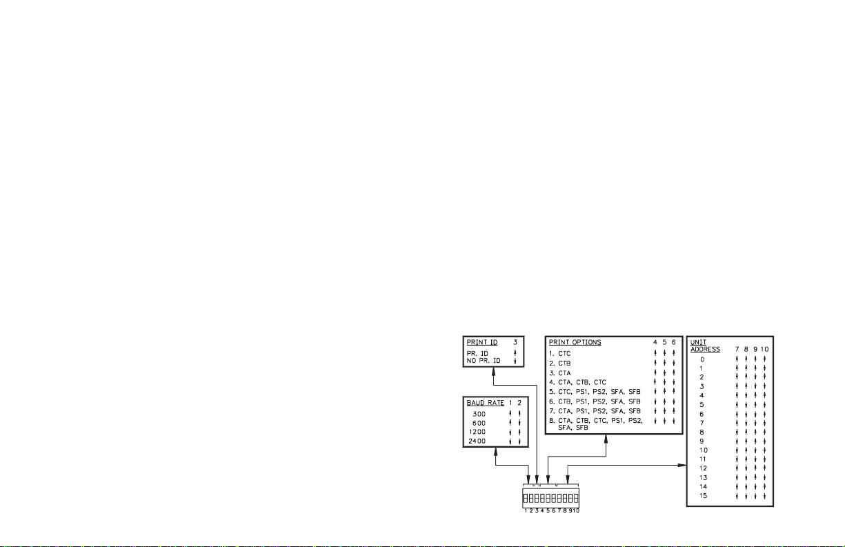
CURRENT LOOP INSTALLATION
WIRING CONNECTIONS
When wiring the 20 mA current loop, remove the 7-position terminal block
(TBD), located on the rightside ofthe topboard. Referto thenumbers listedwith
the terminal descriptions below or on the top label, and install each wire in its
proper location on the terminal block. When all connections are made, replace
the terminal block into its proper location.
It is recommended that shielded (screened) cable be used for serial
communications. This unit meets the EMC specifications using Alpha #2404
cable or equivalent. There are higher grades of shielded cable, such as, four
conductor twisted pair, that offer an even higher degree of noise immunity.
TERMINAL DESCRIPTIONS FOR TERMINAL BLOCK TBD
1. -20 mA SRC (COMM.) - Common for 20 mA SRC and Print Request
terminal.
2. PRINT REQUEST - The Print Request Terminal is pulled low to request the
Gemini 5200 to transmit according to the Print Options mode that has been
selected. (Minimum Activation time = 25 msec.)
3. +20 mA SRC - The 20mA SRC terminal provides the sourcecurrent forone of
the loops.
4. SO- (Serial Out-)
5. SO+ (Serial Out+)
The Gemini 5200 transmits the requested data on these terminals. They are
connected in series to the receive input of the device to be connected.
6. SI- (Serial In-)
7. SI+ (Serial In+)
The Gemini 5200 receives commands on these terminals. They are connected
in series with the transmit or output terminals of the device to be connected.
Note: The serial input terminals must be held in the mark condition (current on)
in order forthe Gemini5200 to respond toa Print Request terminalactivation.
SERIAL DIP SWITCH SET-UP
The SerialDIP switchesare accessible through the side of the Gemini 5200. A
list of the DIP switch positions and their functions are shown in Figure 4.
BR0 & BR1, BAUD RATE - Set-up is shown in Figure 4. When changing the
Baud Rate, the unit should be powered-down and then powered back up again.
The unit will only recognize a baud rate change upon power-up, after
activating the “Print Request” terminal or after a few characters have been
sent at the new baud rate (If the two previous conditions have not occurred, the
Gemini will see the charactersas erroneous and it willcheck the baud rate and
set itself to operate at the new rate).
PR.ID - PRINT ID. - When this switch is in the up position, the Gemini 5200
will print the unit address, data value ID and the data value when a
transmission is requested. The unit will also insert a 400 msec delay between
transmissions when the “P” command or Print Request terminal is used. This
switch position is generally used when the unit is connected with a printer.
When the switch is in the down position, the Gemini 5200 will transmit only the
data value, without the unit address and data ID. The 400 msec delay, described
above, willnot be inserted. This switch position usageis intended for applications
where the Gemini is communicating with a computer. In these circumstances
printing the address and value ID and inserting a 400 msec print delay is usually
unnecessary and needlessly slows down communication throughput.
PC0, PC1, & PC2, PRINT OPTIONS - Used to control which values are
printed out when the Print Request terminal is activated or when the Transmit
per Print Options command “P” is sent to the Gemini 5200.
AD0, AD1, AD2, & AD3 UNIT ADDRESS - These switches are used to give
each unit a separate address when more than one unit is connected in the Loop.
See Figure 4, for Switch Set-up.
FIG. 4: DIP SWITCH SET-UP
-27-
Page 30
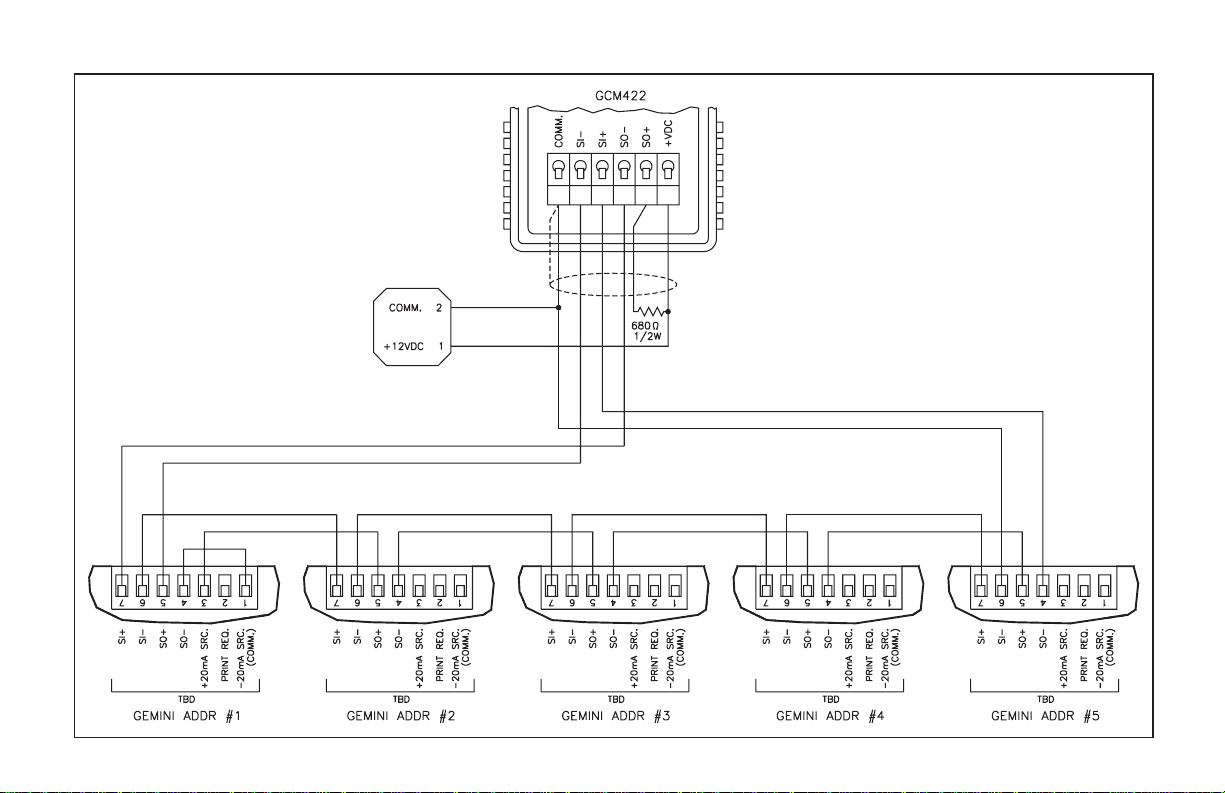
COMMUNICATIONS APPLICATION
PROCESS MONITORING SYSTEM
Five Gemini5200s with20 mACurrent LoopOption, areused
to monitor the speed and draw of various rollers in a printing
facility. The units are located near the printing presses in the
production area of the building. The communications lines are
run to an Industrial computer located in the production offices.
[OTHER GEMINIS OR RLC PRODUCTS WITH 20 MA CURRENT LOOP
CAN BE CONNECTED IN THE SAME LOOP.]
Note: A Serial Converter Module
is available for interfacing an
RS232 device to Geminis.
The drawing below shows the Current Loop set-up. Each
Gemini 5200 is given an address and the Serial DIP switches
are set accordingly. A Baud Rate of 1200 is selected and set
in each of the Gemini 5200s. An application program is
written, which sends and retrieves data from the units using
the Change and Transmit Value commands.
-28-
Page 31

TROUBLESHOOTING GEMINI SERIAL COMMUNICATIONS
If problems are encountered when trying to get the Gemini(s) and host device or
printer to communicate, the followingchecklist canbe usedto help find the solution.
1. Checkall wiring.Refer tothe previous application examples and use them as a
guide to check your serial communication wiring. Proper polarity of all
Geminis and other peripherals mustbe observed.If a multimeter or ammeteris
available, insert it in series in each Serial loop and check for current flow with
all units powered up. If no current is flowing, either the loop is not wired
correctly, or some other fault has occurred. If too much current has been sent
through a Serial Inputor Output,the unitmay havebeen damaged.If aGemini
is suspected, it can be tested for operation by using the Serial Loop-back test
described in the next section.
2. If the Gemini is set-up with a “host computer”, device or printer, check to
make sure that the computer or device is configured with the same
communication format as the Gemini. The only communication format the
Gemini will accept is; 1 start bit, 7 data bits, odd parity, and 1 stop bit.
3. Checkthe baud rate settings and make sure all devices in theloop are set to the
same baud rate.
4. Check the Gemini’s unit address. If the Address command is not used when
transmitting acommand to the Gemini, theGemini’s address must be set to 0.See
“Sending Commands & Data to the Gemini” section for command structure.
5. If two-way communications are to be established between the Gemini and a
computer, try getting the computer to receive transmissions from the Gemini
first. The Gemini’s “PRINT REQ.” terminal can be used to initiate the
transmissions from the Gemini.
6. When sending commands to the Gemini, the * (2Ah) must terminate the
command. NO CARRIAGE RETURNS (0Dh) OR LINE FEED (0Ah)
CHARACTERS SHOULD BE SENT TO THE GEMINI. If they are sent, the
Gemini will not respond to the next command.
7. Forapplications where 1200 Baud orlower is used, the commandterminator (*)
can be sent before the string to eliminate any illegally transmitted characters.
SERIAL LOOP-BACK SELF-TEST
The Gemini 5200 has a Serial Loop-back Self-test feature. This test enables the
user toverify theoperation ofthe Geminiwhen problemsare encountered trying to
get theGemini and “Host device” communicating. In thistest, the Gemini’s Serial
Input and Output Loops are connected together with the 20 mA source supplying
the loop current. The Gemini then transmits data “to itself”. If the data is received
properly, the Gemini 5200 will change its Scale Factor B value to 0.1111. To
perform the loop-back test, follow the test sequence as described below.
1. With the unit powered down, wire up the serial terminal block, “TBD”,as
shown in the diagram below.
2. Set the Gemini’s unit address to 15 (set switches 7-10 of the Serial DIP Switch
to the down position).
3. Apply power to the unit. On power-up the Gemini will perform the loop-back
test. Tocheck the results: Call up the Scale Factor B valueby pressing the “3”
key while the Rate B value is being displayed. If the Serial loop is functioning
properly the Scale Factor B value will be 0.1111. If this result is not obtained,
double check the connections with those shown in the diagram, and the unit
address switch positions and repeat step 3.
4. If the connection between the Print Request terminal, “PRINT REQ.” and
“COMMON” is disconnected while the unit is under power, the Scale Factor
B value will change back to its previous setting.
If the unit does notpass thistest, contactyour local Red Lion Controls distributor.
-29-
Page 32

APPENDIX “A” - INSTALLATION & INPUT CONFIGURATION SWITCH SET-UP
Before installing the Gemini 5200 into the panel,the user should first become
familiar with the unit. It may also be desirable to program the unit for the
application at hand (Refer to the “Programming and Applications” sections).
Once the unitis programmed,the settingswill besaved inmemory. TheProgram
Disable “PGM. DIS.” terminal should be connected to “COMM.” to prevent
accidental or unauthorized programming changes.
PANEL MOUNTING {Note: See Appendix “B” for Dimensions}
Installation Environment
The GEM5200 should be installed in a location that does not exceed the
maximum operating temperature and provides good air circulation. Placing the
unit near devices that generate excessive heat should be avoided.
The bezel should be cleaned only with a soft cloth and neutral soap product.
Do NOTuse solvents. Continuous exposure to direct sunlight may acceleratethe
aging process of the bezel.
Do not use tools of any kind (screwdrivers, pens, pencils, etc.) to operate the
keypad of the unit.
The Gemini 5200 is intendedto be mounted intoan enclosed panel with
a gasket to provide a water-tight seal. The unit meets NEMA 4/IP65
requirements forindoor use when properly installed. Two mounting clips
and screws are provided for easy installation. Consideration should be
given to the thickness of the panel. A panel which is too thin may distort
and not provide a water-tight seal. (Recommended minimum panel
thickness is 1/8".)
After the panel cut-out has been completed and deburred, remove the
backing from the adhesive side of the gasket, and carefully apply the
gasket to the panel. DO NOT
GASKET TO THE COUNTER BEZEL. Insert the unit into the panel.
Install the screws into the narrow ends of the mounting clips as shown in
the drawing to the left. Thread the screws into the clips until the pointed
end just protrudes through the other side.
Install each of the two mounting
clips by inserting the wide lip of the
clips into the wide end of the holes
located on either side of the case.
Tighten the screws evenly,
applying uniform compression,
thus providing a water-tight seal.
Caution: Onlyminimum pressureis
required to seal panel. Do NOT
over tighten mounting screws.
APPLY THE ADHESIVE SIDE OF THE
-30-
Page 33

SELECT AC POWER (115/230 VAC)
The AC power to the unit must be selected for either 115 VAC or 230 VAC.
The selector switch is located through an access slot on the side of the case (See
the Installation Figure on the previous page, or the label on the case). The unit is
shipped from the factory with the switch in the 230 VAC position.
Caution: Damage to the unitmay occur if the ACselector switchis set incorrectly.
EMC COMPLIANCE INSTALLATION
This unit complies with the Electromagnetic Compatibility (EMC) standards
listed in the specifications. Compliance to the EMC standards was demonstrated
by means of a test set-up using the following installation methods:
1. Unit mounted in a metal panel connected to earth ground (protective earth).
2. Shielded (screened) cables for Signal and Control inputswith shielddrain wire
connected to earth ground at the mounting panel only.
Belden #8451 2conductor, #22AWG twisted pair withfoil shield and drainwire
Belden #8771 3 conductor, #22 AWG with foil shield and drain wire
Alpha #2404 4 conductor, #22 AWG with foil shield and drain wire
3. Metal bezel of unit connected to mounting panel with 9 inch (23 cm) ground
lead from rear bezel screw. Test: Immunity to ESD per EN61000-4-2.
4. EMI filter (Shaffner FN610) placed on the DC mains cable when using
optional DC power supply. Test: EFT Immunity per EN61000-4-4.
SHIELD TERMINATION
EMC compliance installation testing had the drain wire for the shielded cable
terminated as shown. The drain wire was less than 0.5" (12.7 mm) long.
-31-
Page 34

ADDITIONAL EMC INSTALLATION GUIDELINES
Although this unit is designed with a high degree of immunity to
ElectroMagnetic Interference (EMI), proper installation and wiring methods
must be followed to ensure compatibility in each application. The type of the
electrical noise, source or coupling method into the unit may be different for
various installations. Listed below are some additional EMC guidelines for
successful installation in an industrial environment.
1. The unit should bemounted in a metal enclosure, which is properly connected
to protective earth.
a. If the bezel is exposed to high Electro-Static Discharge (ESD) levels,
above 4Kv, it should be connected to protective earth. This can be done
by making surethe metal bezel makes proper contact tothe panelcut-out
or connecting the bezel screw with a spade terminal and wire to
protective earth.
2. Use shielded (screened) cables for all Signal and Control inputs. The shield
(screen) pigtail connection should be made as short as possible. The
connection point for the shield depends somewhat upon the application.
Listed below are the recommended methods of connecting the shield, in order
of their effectiveness.
a. Connect the shield only at the panel where the unit is mounted to earth
ground (protective earth).
b. Connect the shield to earth ground at both ends of the cable, usually
when the noise source frequency is above 1 MHz.
c. Connect the shield to common of the unit and leave the other end of the
shield unconnected and insulated from earth ground.
3. Never run Signal or Control cables in the same conduit or raceway with AC
power lines, conductors feeding motors, solenoids, SCR controls, and heaters,
etc. The cables should be run in metal conduit that is properly grounded. This
is especially useful in applications where cable runs are long and portable
two-way radios are used in close proximity or if the installation is near a
commercial radio transmitter.
4. Signal or Control cables within an enclosure should be routed as far away as
possible from contactors, control relays, transformers, and other noisy
components.
5. In very electrically noisy environments, the use of external EMI suppression
devices, such as ferrite suppressioncores, is effective. Install themon Signaland
Control cables as close to the unit as possible. Loop the cable through the core
several times or use multiple cores on each cable for additional protection.
Install line filters on the power input cable to the unit to suppress power line
interference. Install them near the power entry point of the enclosure. The
following EMI suppression devices (or equivalent) are recommended:
Ferrite Suppression Cores for signal and control cables:
Fair-Rite # 0443167251 (RLC #FCOR0000)
TDK # ZCAT3035-1330A
Steward #28B2029-0A0
Line Filters for input power cables:
Schaffner # FN610-1/07 (RLC #LFIL0000)
Schaffner # FN670-1.8/07
Corcom #1VR3
Note: Reference manufacturer’s instructions when installing a line filter.
6. Long cable runs are more susceptible to EMI pickup than short cable runs.
Therefore, keep cable runs as short as possible.
7. Switching of inductive loads produces high EMI. Use of snubbers across
inductive loads suppresses EMI.
Snubbers: RLC #SNUB0000
WIRING CONNECTIONS
After the unit has been mechanically mounted, it is ready to be wired. All
conductors should meet voltage and current ratings for each terminal. Also
cabling should conform to appropriate standards of good installation, local codes
and regulations. It is recommended that power supplied to the unit (AC orDC) be
protected by a fuse or circuit breaker. All wiring connections are made on
removable plug-in terminal blocks. There is a separate terminal block for the
bottom board (TBA), relay board (TBB), rate inputs (TBC), and optional Serial
Communications (TBD). When wiring the unit, remove the terminal block and
use the numbers on the label to identify the position number with the proper
function. Simply strip the wire, leaving approximately 1/4" bare wire exposed
(stranded wires should be tinned with solder). Insert the wire into the terminal
and tighten down the screw until the wire is clamped intightly. Eachterminal can
accept up to two 18-gage wires. After the terminal block is wired, install it in the
proper location on the PC board. Wire each terminal block in this manner.
-32-
Page 35

PRIMARY A.C. WIRING
For bestresults, the A.C. primary power should berelatively “clean” and within
the specified +/-10% variation limits. Drawing power from heavily loaded circuits
or from circuits that also power loads that cycle on and off, should be avoided.
The ACpower isconnected tothe bottomleft terminals TBA 1 & 2, marked as
AC Power, 50/60 Hz. The voltage selectorswitch, located on the sideof the unit,
is used to select the proper voltage. The switch is a slide movement type and can
be set by using a small screwdriver. If the switch is towards thefront ofthe unit,it
is set for 230 VAC input. The switch is in the 230 VAC position when shipped
from the factory.
Note: Beforeapplying power to the unit, make sure the AC power selectorswitch
is set for the proper voltage setting.
USING AN EXTERNAL DC POWER SOURCE
The Gemini 5200 can be operated from a D.C. power source that provides
11-14 VDC at the unit’s rated power consumption (700 mA). The power source
can bea 12 V battery or an external powersupply that is capable of supplying the
unit’s rated current. It is not necessary to provide battery backup to retain
programming information. The Gemini 5200 has an internal non-volatile
memory in which the programming information is stored upon power-down.
Refer to the “Block Diagram” section.
RELAY WIRING
To prolong contact life and suppress electrical noise interference due to the
switching of inductive loads, it is good installation practice to install a snubber
across the contactor. Follow the manufacturer’s instructions for installation.
Note: Snubberleakage current can cause some electro-mechanical devices to be
held ON.
SERIAL COMMUNICATIONS
The Gemini 5200 can be purchased with a 20 mA Current Loop
Communications Option. On these units, refer to the “Current Loop
Communications” section of the manual for wiring and operational procedures
of the Serial Loop.
INPUTSA&BANDMAGNETIC PICKUP INPUTSA&B
The Gemini 5200 has two input channels. Input Channel A is associated with
Rate Display A and Channel B is associated with the Rate Display B. The
Magnetic Pickup Input and theLogic Inputof each channel utilize somecommon
circuitry. For this reason the Input switches are used to set up both the Magnetic
and Logic Input.
S1 selects between Magnetic Pickup Input A and Logic Input A. S5 selects
between Magnetic Pickup Input B and Logic Input B. WHEN MAGNETIC
PICKUP A IS BEING USED, S2 MUST BE IN THE “SNK” POSITION or the
unit will not display the rate properly. Likewise, WHEN MAGNETIC PICKUP
B IS BEING USED, S6 MUST ALSO BE IN THE “SNK” POSITION.
S3 (HI/LO FRQ) and S4 (HI/LO BIAS) or S7 (HI/LO FRQ) and S8 (HI/LO
BIAS) do not effect the Magnetic Pickup InputsA&Bandtheir settings are
inconsequential. When S1 or S5 is in the Logic position, the Magnetic Pickup
Input A or B is disabled and Inputs A or B can be used as logic inputs.
Note: A Magnetic Pickup type sensor should not be used unless a large enough
signal is provided at all speeds of operation.
-33-
Page 36

BLOCK DIAGRAM
-34-
Page 37

CONNECTIONS & CONFIGURATION SWITCH SET-UPS FOR VARIOUS SENSOR OUTPUTS (See Note 5)
-35-
Page 38

Notes:
1. SENSOR VOLTAGE AND CURRENT
The +12 V sensor supply voltage on the “DC OUT” terminal is nominal with
+/-25% variation due to line and internal load variations. All RLC sensors
will accommodate this variation.
2. HI/LO FRQ SELECTION
The HI/LO FRQ selection switch must be set on “LO FRQ” when switch
contacts are used to generate rate input signals. Since the “LO FRQ” mode
also provides very high immunity against electrical noise pickup, it is
recommended that this mode alsobe used, whenever possible, with electronic
sensor outputs. The “LO FRQ” mode can be used with any type of sensor
output, provided pulse widths never decrease below 5 msec, and the rate does
not exceed 100 cps.
3. V
and VIHlevels given are nominal values +/-10% when the voltage on “DC
IL
OUT” terminal is +12 VDC. These nominal values will vary in proportion to
the variations in the “DC OUT” terminal voltage, which are caused by line
voltage and load changes.
4. When shielded cable is used, the shield should be connected to “COMM.” at
the counter and left unconnected at the sensor end.
5. Inputs A and B can accept source pulses from other circuits up to +28 V in
amplitude. For voltages above +28 V, a limiting resistor and zener diode
should be used to limit the voltage at the input.
INSTALLATION & REMOVAL OF THE RELAY BOARD
To install the relay board, locate the relay opening at the lower right-hand
corner, onthe backof theGemini 5200. Pull the tab down while sliding the board
into the two slots in the housing. The relay board will seat into the unit, allowing
the tab to return to its original position. To remove the relay board, pull down on
the tab just enough to allow the relay board to slide out. Grasp the six terminal
connector and pull to remove the board.
-36-
Page 39

SENSOR INPUT CONNECTIONS & INPUT CONFIGURATION
SWITCH SET-UP
The accompanying diagram shows the details of the logic and magnetic
pickup circuitry. The four switches used to set up Logic Input A and Magnetic
Pickup A are designated S1, S2, S3, and S4. The four switches used to set up
Logic Input B and Magnetic Pickup B are designated S5, S6, S7, and S8. The
functions of these switches are as follows:
S1 - MAG: Enables the Magnetic Pickup terminal to be used.
LOGIC: Disables the Magnetic Pickup Input.
Note: SWITCH S2 MUST BE IN THE “SNK” POSITION FOR
MAGNETIC PICKUP OPERATION.
S2 -SNK: Provides a 7.8 K pull-up resistor for sensorswith current sinking
outputs.
SRC: Provides a 3.9 K pull-down resistor for sensors with current
sourcing outputs.
S3 - HI FRQ: Removes damping capacitor and allows operation up to the
max. count frequency. Min. count ON or OFF time - 50 usec.
LO FRQ: Connects damping capacitor for switch contact debounce.
Limits count speed to 100cps max. Min. count pulseON or OFF time 5 msec. (See Note 2.)
S4 - HI BIAS: Sets input trigger levels at mid-range to accept outputs from
2-wire proximity sensors, resistive photo-cells, and logic pulses with
full 0 to +12 V swings. (V
LO BIAS: Sets input trigger levels to the low range to accept logic
pulses with 0to 5V swings. (V
S5 - Same as S1, for Magnetic pickup B and Logic Input B.
S6 - Same as S2, for Magnetic pickup B and Logic Input B.
S7 - Same as S3, for Logic Input B.
CHAN. B CHANNEL A
S8 - Same as S4, for Logic Input B.
S9 - DIS. RST.: Disables front panel Reset button, “R”.
EN. RST.: Enables front panel Reset button “R”, if “Operator
Accessible Functions” mode (code 66) has reset enabled.
S10 - Not used.
= 5.5 V, VIH= 7.5 V, See Note 3.)
IL
= 1.5 V,VIH= 3.75 V,See Note3.)
IL
Note: The circuitry for Channel B (Input B and Mag. Pkup.) is identical to
that shown for A.
-37-
Page 40

APPENDIX “B” - SPECIFICATIONS & DIMENSIONS
1. DISPLAY: 6-digit 0.56" (14.2 mm) High LED display.
2. POWER REQUIREMENTS:
AC Power: Switch selectable 115/230 VAC (±10%), 50/60 Hz, 20 VA
DC Power: 11 to 14 VDC @ 0.7 amp max.
3. SENSOR POWER: +12 VDC (±25%) @ 100 mA.
4. MEMORY: Non-volatile E
2
PROM memory retains all programming
information when power is removed or interrupted.
Power Cycles (ON/OFF): 100,000 min.
Data Retention: 10 yrs. min.
5. INPUTS A AND B: Switch selectable to accept pulses from a variety of
sources including switch contacts, outputs from CMOS or TTL circuits, and
all standard RLC sensors.
Current Sourcing - Unit provides 3.9 K pull-down resistor for sensor with
current sourcing outputs. (Max. input voltage = 28 VDC @ 7 mA.)
Current Sinking - Unit provides 7.8 K pull-up resistor for sensors with
current sinking outputs. (Max. sensor current = 1.6 mA.)
Debounce -Damping capacitor provided for switch contact debounce.Limits
rate to 100 Hz max. and input pulse widths to 5 msec. min.
Lo Bias - Input trigger levels V
Hi Bias - Input trigger levels V
DIMENSIONS In Inches (mm)
= 1.5 V, VIH= 3.75 V
IL
= 5.5 V, VIH= 7.5 V
IL
Note: Mounted units require a clearance of 6.8" (W) behind the panel.
Note: Bias levels given are ±10% @ 12 VDC. They vary proportionally with
sensor supply voltage at “DC OUT” terminal.
6. MAGNETIC PICKUP INPUTSA&B:
Sensitivity: 150 mV peak (typical @ 12 VDC)
Hysteresis: 100 mV
Input impedance: 26.5 KW @60Hz
Maximum Input Voltage: ±50 Vp
7. RATE ACCURACY AND REPEATABILITY: +0.025%
8. RATE MINIMUM INPUT FREQUENCY: 0.03 Hz
Note: At frequencies below 0.03 Hz (1 pulse every 32 sec.) the rate indicator
will display a zero.
9. RATE MAXIMUM INPUT FREQUENCY: 10 KHz
10. CONTROL INPUTS:
Reset - Active low (V
3 mA), Activation & De-activation response time = 10 msec.
Program Disable - Active low (V
VDC (I
Print Request - (GEM521xx only) Active low, (V
SNK
= 1 mA).
pulled up to +5 VDC (I
= 1.5 V max.), internally pulled up to +12VDC (I
IL
= 1.5 V max.), internally pulled up to +5
IL
= 1.5 V max.), internally
SNK
= 1 mA).
IL
SNK
=
-38-
Page 41

11. SERIAL COMMUNICATIONS:
Type - Bi-directional 20 mAcurrent loop,20 mA source provided.(Powers up
to 7 units in a loop with internal current source.)
Baud Rate - Programmable 300 to 2400.
Maximum Address - 16 units. (Actual number in a single loop is limited by
serial hardware specifications.)
Data Format - 10 bit frame, Odd parity (one start bit, 7 data bits, one odd
parity bit, and one stop bit.)
Serial Hardware Specifications -
SO - Output Transistor Rating: V
SI - Input Diode Rating: V
Note: The compliancevoltage ratingof the source mustbe greater than the
F
max
= 1.25 V
= 30 VDC, V
; 1.5 Vmax
TYP
SAT
=1V
max
at 20 mA
sum of the voltage drops around the loop.
12. OUTPUTS:
Solid-State - Current sinking NPN open collector transistors. I
maximum @ V
protection).
=1V.VOH= 30 VDC max. (Internal Zener diode
CE
SNK
= 100 mA
Relays - Mounted on a field replaceable PC board. Form C contacts rated at 5
amps @ 120/240 VAC or 28 VDC (resistive load), 1/8 H.P. @ 120 VAC
(inductive load). The operate time is 5 msec. nominal and the release time is 3
msec. nominal.
Relay Life Expectancy - 100,000 cycles at Max. Rating. (As load level
decreases, life expectancy increases.)
Programmable Timed Outputs - The timed outputs can be set from 0.01 to
599.99 seconds, +/-(0.01% + 10 msec.).
13. ENVIRONMENTAL CONDITIONS:
Operating Temperature: 0 to 50°C
Storage Temperature: -40 to 70°C
Operating and Storage Humidity: 85% max. relative humidity
(non-condensing) from 0°C to 50°C.
Altitude: Up to 2000 meters
14. CERTIFICATIONS AND COMPLIANCES:
SAFETY
IEC 1010-1, EN 61010-1: Safety requirements for electrical equipment
for measurement, control, and laboratory use, Part 1.
IP65 Enclosure rating (Face only), IEC529
Type 4 Enclosure rating (Face only), UL50
ELECTROMAGNETIC COMPATIBILITY:
Immunity to EN 50082-2
Electrostatic discharge EN 61000-4-2 Level 2; 4 Kv contact
Level 3; 8 Kv air
Electromagnetic RF fields EN 61000-4-3 Level 3; 10 V/m
80 MHz - 1 GHz
Fast transients (burst) EN 61000-4-4 Level 4; 2 Kv I/O
Level 3; 2 Kv power
RF conducted interference EN 61000-4-6 Level 3; 10 V/rms
150 KHz - 80 MHz
Power frequency magnetic fields EN 61000-4-8 Level 4; 30 A/m
Emissions to EN 50081-2
RF interference EN 55011 Enclosure class A
Power mains class A
Notes:
1. Metal bezel of unit connected with ground lead from rear bezel screw to
metal mounting panel.
2. When the unit is DC powered, a power line filter (RLC #LFIL0000 or
equivalent) was installed, so as not to impair the function of the unit.
Refer to the EMC Compliance Installation section of the manual for
additional information.
15. CONSTRUCTION:
Metal die-cast bezel, plastic case. This unit is rated for NEMA 4/IP65 indoor
use. Installation Category II, Pollution Degree 2
16. WEIGHT: 2.1 lbs (0.9 kg)
1
2
-39-
Page 42

APPENDIX “C” - TROUBLESHOOTING GUIDE
The majority of difficulties arising with the Gemini 5200 are related to incorrect hook-up
and programming set-up. Always check all connections, function codes, Scale Factor, and
presets as a first step in troubleshooting.
Before applying power, double check all wiring. Improper AC voltage or AC connections
may result in permanent damage to the unit.
For further technical assistance, contact technical support at the appropriate company
numbers listed on the back cover of this instruction manual.
PROBLEM POSSIBLE CAUSE REMEDIES
NO DISPLAY 1. Power off, improperly connected, or power 1. Check all wiring, verify power.
P ON DISPLAY 1. Data error on power-up. 1a. Press “E” key.
E ON THE DISPLAY 1. Data error detected by processor. 1a. Press “E” key.
NO RESPONSE TO FRONT PANEL 1. Panel disabled. 1. Consult manual on “Operator Accessible
NO RATE INDICATION 1. No input. 1. Check sensors/connections.
brown-out.
b. Check all function codes.
b. Check all function codes.
c. Check signal lines for possible noise sources.
Functions" modes.
2. Input selected incorrectly. 2. Check rear panel DIP switches.
3. Scale factor/multiplier too small. 3. Check scale factor value and scale
multiplier values.
4. Input frequency below 0.03 cps. 4. At frequency under 0.03 cps (1 pulse every
32 sec) the display will read zero.
-40-
Page 43

APPENDIX “C” - TROUBLESHOOTING GUIDE
PROBLEM POSSIBLE CAUSE REMEDIES
INCORRECT RATE READING 1. Input type incorrectly selected. 1. Check rear panel DIP switches. Turn on LO.
2. Inputs incorrectly connected or loose connections. 2. Check sensors/input connections.
3. Electrical interference. 3. Check connections and wiring for noise
4. Incorrect scaling. 4. Review scaling parameters (Appendix “F”).
OUTPUT WILL NOT RESET 1. Front panel reset disabled. 1. Check rear panel DIP switch.
2. Reset disabled. 2. Check function code 42 or 66.
DATA VALUES AND FUNCTIONS WILL 1. Front panel locked out. 1. Consult manual on “Operator Accessible
NOT CHANGE OR NOT RECORDED Functions” mode (66)
2. Incorrect programming procedure (“E” not pressed). 2. Consult section on programming functions in
-41-
FRQ. switch for count speed of less than 100
cps.
sources.
sequential order.
Page 44

APPENDIX “D” - GEMINI 5200 DUAL RATE W/O DISP C FUNCTION COMMAND CODE SUMMARY
CODE MODE DESCRIPTION COMMENTS
41 UNIT PERSONALITY (-)Loads factory set code values*
42 RESET BUTTON & TERMINAL ACTUATION MODES
43 RATE B CONVERSION FACTOR
44 RATE B MINIMUM UPDATE TIME
45 RATE B SCALE MULTIPLIER
46 RATE B DECIMAL POINT & LEAD ZERO BLANKING
* Polarity sign is displayed in front of the identifier, a (-) sign is displayed, a (+) sign is not.
+/-1 Dual Rate W/O Display C Rate AÞDisplay A, Rate BÞDisplay B
+/-2 Dual Rate W/ Ratio (A/B) See Appendix “E” for a Function Command Code
+/-3 Dual Rate W/ Difference (A-B) Summary when in these modes
+/-4 Dual Rate W/ Draw [(A-B)/B]
1 Reset Rate A Output(s) Reset only affects the output(s) and does not
2 Reset Rate B Output(s) change the rate display.
3 Reset RateA&BOutputs
1 Rate Per Second (x1)
2 Rate Per Minute (x60)
3 Rate Per Hour (x3600)
1 0.5 sec minimum/1 sec maximum
2 1 sec minimum/2 sec maximum
3 2 sec minimum/4 sec maximum
4 4 sec minimum/8 sec maximum
5 8 sec minimum/16 sec maximum Maximum rate = 7500 cps.
6 16 sec minimum/32 sec maximum Maximum rate = 3250 cps.
1 x1000
2 x100
3 x10
4 x1
5 x0.1
6 x0.01
(+) Leading Zero Blanking Enabled
(-) Leading Zero Blanking Disabled*
-42-
Page 45

APPENDIX “D” - GEMINI 5200 DUAL RATE W/O DISP C FUNCTION COMMAND CODE SUMMARY
CODE MODE DESCRIPTION COMMENTS
46 RATE B DECIMAL POINT & LEAD ZERO BLANKING
+/-1 No Decimal Point
+/-2 Decimal Point Right of Digit 2
+/-3 Decimal Point Right of Digit 3
+/-4 Decimal Point Right of Digit 4
+/-5 Decimal Point Right of Digit 5
+/-6 Decimal Point Right of Digit 6
51 OUTPUT ASSIGNMENT
+/-1 Output 1 to Rate A, Output 2 to Rate B
+/-2 Outputs1&2toRate B
+/-3 Outputs1&2toRate A
52 OUTPUT 1 TERMINATION MODES
+/-3 Terminate at Manual Reset
+/-4 Terminate at Manual Reset End
+/-5 Terminate after Timed Output 1
+/-6 Boundary
53 TIMED OUTPUT 1 VALUE Range 0.01 to 599.99 sec.
54 OUTPUT 2 TERMINATION MODES
+/-3 Terminate at Manual Reset
+/-4 Terminate at Manual Reset End
+/-5 Terminate after Timed Output 2
+/-6 Boundary
55 TIMED OUTPUT 2 VALUE Range 0.01 to 599.99 sec.
*Polarity sign is displayed in front of the identifier, a (-) sign is displayed, a (+) sign is not.
(Cont’d)
(+) Preset Tracking disabled
(-) Preset Tracking enabled* Preset 1 tracks Preset 2
(+) Normal Phase Output normally “OFF”, turns “ON” at preset.
(-) Reverse Phase* Output normally “ON”, turns “OFF” at preset.
(+) Normal Phase Output normally “OFF”, turns “ON” at preset.
(-) Reverse Phase* Output normally “ON”, turns “OFF” at preset.
-43-
Page 46

APPENDIX “D” - GEMINI 5200 DUAL RATE W/O DISP C FUNCTION COMMAND CODE SUMMARY
CODE MODE DESCRIPTION COMMENTS
56 RATE B RIGHT-HAND DUMMY ZEROS
61 RATE A RIGHT-HAND DUMMY ZEROS
62 RATE A CONVERSION FACTOR
63 RATE A MINIMUM UPDATE TIME
64 RATE A SCALE MULTIPLIER
* Polarity sign is displayed in front of the identifier, a (-) sign is displayed, a (+) sign is not.
1 1 Dummy Zero
2 2 Dummy Zeros
3 3 Dummy Zeros
4 No Dummy Zeros
1 1 Dummy Zero
2 2 Dummy Zeros
3 3 Dummy Zeros
4 No Dummy Zeros
1 Rate Per Second (x1)
2 Rate Per Minute (x60)
3 Rate Per Hour (x3600)
1 0.5 sec minimum/1 sec maximum
2 1 sec minimum/2 sec maximum
3 2 sec minimum/4 sec maximum
4 4 sec minimum/8 sec maximum
5 8 sec minimum/16 sec maximum Maximum rate = 7500 cps.
6 16 sec minimum/32 sec maximum Maximum rate = 3250 cps.
1 x1000
2 x100
3 x10
4 x1
5 x0.1
6 x0.01
-44-
Page 47

APPENDIX “D” - GEMINI 5200 DUAL RATE W/O DISP C FUNCTION COMMAND CODE SUMMARY
CODE MODE DESCRIPTION COMMENTS
65 RATE A DECIMAL POINT & LEAD ZERO BLANKING
+/-1 No Decimal Point
+/-2 Decimal Point Right of Digit 2
+/-3 Decimal Point Right of Digit 3
+/-4 Decimal Point Right of Digit 4
+/-5 Decimal Point Right of Digit 5
+/-6 Decimal Point Right of Digit 6
66 “OPERATOR ACCESSIBLE FUNCTIONS” MODES “PGM DIS” Terminal connected to “Comm”
+/-1 No Functions Enabled
+/-2 Preset Programming Enabled
+/-3 Scale Factor Programming Enabled
+/-4 Preset & Scale Factor Programming Enabled
1 PRESET 1 Up to +/-999999
2 PRESET 2
3 Display A RATE A SCALE FACTOR Up to 5.9999
3 Display B RATE B SCALE FACTOR
* Polarity sign is displayed in front of the identifier, a (-) sign is displayed, a (+) sign is not.
(+) Leading Zero Blanking Enabled
(-) Leading Zero Blanking Disabled*
(+) Reset Button & “RST” Terminal Enabled Front panel reset can be independently disabled by using
the Input Configuration DIP switch.
(-) Reset Button & “RST” Terminal Disabled* This mode has no affect on the “RST A” terminal which is
always enabled.
-45-
Page 48

APPENDIX “E” - GEMINI 5200 DUAL RATE W/ DISP C FUNCTION COMMAND CODE SUMMARY
CODE MODE DESCRIPTION COMMENTS
41 UNIT PERSONALITY (-)Loads factory set code values*
42 RESET BUTTON & TERMINAL ACTUATION MODES
43 RATE B CONVERSION FACTOR
45 RATE B SCALE MULTIPLIER
46 DISPLAY C DECIMAL POINT & LEAD ZERO BLNKNG
* Polarity sign is displayed in front of the identifier, a (-) sign is displayed, a (+) sign is not.
+/-1 Dual Rate W/O Display C See Appendix "D" for function command code summary.
+/-2 Dual Rate W/ Ratio (A/B) RateA&BÞDisplay valueA&B,
Ratio (A/B)ÞDisplay Value C
+/-3 Dual Rate W/ Difference (A-B) RateA&BÞDisplay valueA&B,
Difference (A-B)ÞDisplay Value C
+/-4 Dual Rate W/ Draw [(A-B)/B] RateA&BÞDisplay valueA&B,
Draw [(A-B)/B]ÞDisplay Value C
1 Reset Rate A Output(s) Reset only affects the output(s) and does not
2 Reset Rate B Output(s) change the rate display.
3 Reset RateA&BOutputs
4 Reset Display C Output(s)
5 Reset Display C & Rate A Outputs
6 Reset Display C & Rate B Outputs
1 Rate Per Second (x1)
2 Rate Per Minute (x60)
3 Rate Per Hour (x3600)
1 x1000
2 x100
3 x10
4 x1
5 x0.1
6 x0.01
(+) Leading Zero Blanking Enabled
(-) Leading Zero Blanking Disabled*
+/-1 No Decimal Point
-46-
Page 49

APPENDIX “E” - GEMINI 5200 DUAL RATE W/ DISP C FUNCTION COMMAND CODE SUMMARY
CODE MODE DESCRIPTION COMMENTS
46 DISPLAY C DECIMAL POINT & LEAD ZERO BLNKNG
+/-2 Decimal Point Right of Digit 2
+/-3 Decimal Point Right of Digit 3
+/-4 Decimal Point Right of Digit 4
+/-5 Decimal Point Right of Digit 5
+/-6 Decimal Point Right of Digit 6
51 OUTPUT ASSIGNMENT
+/-1 Output 1 to Rate A, Output 2 to Rate B
+/-2 Outputs1&2toRate B
+/-3 Outputs1&2toRate A
+/-4 Output 1 to Rate B, Output 2 to Display C
+/-5 Output 1 to Rate A, Output 2 to Display C
+/-6 Outputs1&2toDisplay C
52 OUTPUT 1 TERMINATION MODES
+/-3 Terminate at Manual Reset
+/-4 Terminate at Manual Reset End
+/-5 Terminate after Timed Output 1
+/-6 Boundary
53 TIMED OUTPUT 1 VALUE Range 0.01 to 599.99 sec.
54 OUTPUT 2 TERMINATION MODES
+/-3 Terminate at Manual Reset
+/-4 Terminate at Manual Reset End
+/-5 Terminate after Timed Output 2
+/-6 Boundary
* Polarity sign is displayed in front of the identifier, a (-) sign is displayed, a (+) sign is not.
(Cont’d)
(+) Preset Tracking disabled
(-) Preset Tracking enabled* Preset 1 tracks Preset 2
(+) Normal Phase Output normally “OFF”, turns “ON” at preset.
(-) Reverse Phase* Output normally “ON”, turns “OFF” at preset.
(+) Normal Phase Output normally “OFF”, turns “ON” at preset.
(-) Reverse Phase* Output normally “ON”, turns “OFF” at preset.
-47-
Page 50

APPENDIX “E” - GEMINI 5200 DUAL RATE W/ DISP C FUNCTION COMMAND CODE SUMMARY
CODE MODE DESCRIPTION COMMENTS
55 TIMED OUTPUT 2 VALUE Range 0.01 to 599.99 sec.
61 DISPLAY C MULTIPLIER Not available in mode [41 3], Speed Difference
62 RATE A CONVERSION FACTOR
63 RATE MINIMUM UPDATE TIME
64 RATE A SCALE MULTIPLIER
*Polarity sign is displayed in front of the identifier, a (-) sign is displayed, a (+) sign is not.
1 x1
2 x10
3 x100
4 x1000
5 x10000
1 Rate Per Second (x1)
2 Rate Per Minute (x60)
3 Rate Per Hour (x3600)
1 0.5 sec minimum/1 sec maximum
2 1 sec minimum/2 sec maximum
3 2 sec minimum/4 sec maximum
4 4 sec minimum/8 sec maximum
5 8 sec minimum/16 sec maximum Maximum rate = 7500 cps.
6 16 sec minimum/32 sec maximum Maximum rate = 3250 cps.
1 x1000
2 x100
3 x10
4 x1
5 x0.1
6 x0.01
-48-
Page 51

APPENDIX “E” - GEMINI 5200 DUAL RATE W/ DISP C FUNCTION COMMAND CODE SUMMARY
CODE MODE DESCRIPTION COMMENTS
65 RATEA&BDECIMAL POINT & LEAD ZERO BLNKNG
+/-1 No Decimal Point
+/-2 Decimal Point Right of Digit 2
+/-3 Decimal Point Right of Digit 3
+/-4 Decimal Point Right of Digit 4
+/-5 Decimal Point Right of Digit 5
+/-6 Decimal Point Right of Digit 6
66 “OPERATOR ACCESSIBLE FUNCTIONS” MODES “PGM DIS” Terminal connected to “Comm”
+/-1 No Functions Enabled
+/-2 Preset Programming Enabled
+/-3 Scale Factor Programming Enabled
+/-4 Preset & Scale Factor Programming Enabled
1 PRESET 1 Up to +/-999999
2 PRESET 2
3 Display A RATE A SCALE FACTOR Up to 5.9999
3 Display B RATE B SCALE FACTOR
*Polarity sign is displayed in front of the identifier, a (-) sign is displayed, a (+) sign is not.
(+) Leading Zero Blanking Enabled
(-) Leading Zero Blanking Disabled*
(+) Reset Button & “RST” Terminal Enabled Front panel reset can be independently disabled by using
DIP switch.
(-) Reset Button & “RST” Terminal Disabled* This mode has no affect on the “RST A” terminal which is
always enabled.
-49-
Page 52

APPENDIX “F” - SCALING FOR RATE & DISPLAY C
The Gemini 5200 offers a simplified method of scaling the rate indicator. The
method does not require timeunit conversions. The desired timeformat (Rate Per
Second, Rate Per Minute, Rate Per Hour) is simply selected as part of the
programming procedure.
Due to the way the rate is calculated, high resolution and accuracy can be
realized at allinput rates,slow or fast. Itis not necessary toincrease the number of
pulses per display unit to obtain higher resolution.
The Rate Minimum Update Time, function code 63, can be increased (from
0.5 Sec.up to 16 Sec.) to provideaveraging in applications where the inputpulse
spacing is not stable. The Update time selected, however, will not affect the
scaling in any manner.
Scaling the Rate channel simply involves programming the Gemini 5200 so
that pulse units inputted to the unit will be scaled to the desired display units
(revolutions, feet, meters, etc.), in the desiredtime format (Rate Per Second, Rate
per Minute, Rate Per Hour).
In order to scale the rate, it is only necessary to know the number of pulses per
“Display Unit” or units (feet, revolutions, etc.). For example; if a 48 tooth gear,
which is coupled to a shaft, is being sensed and it is desired to indicate the shaft
speed inrevolutions, the “Display Units” would be revolutions. It is obvious that
48 pulses will occur in one revolution.
In orderto convertthe pulseunits to revolutions, it is necessary for the Gemini
5200 to multiply the number of pulses by a scaling factor to convert the pulse
units to revolutionunits. TheGemini 5200 has twoprogramming codes that serve
to scale pulse units to desired display units. They are: the Scale Factor and the
Scale Multiplier. Both are used to attain the Total Scaling Factor, “K
To calculatethe Total Scaling Factor, “KT”, for theapplication, the following
”.
T
formula is used.
FORMULA #1: K
= Display Units/Number of Pulses
T
WHERE:
DISPLAY UNITS
- The number of units(revolutions, feet,10ths of feet, meters,
etc.) that would be acquired after the “Number of Pulses” has occurred.
NUMBER OF PULSES
- The Numberof pulsesrequired toachieve thenumber
of “Display Units”.
Using the example previously discussed, the display unit would be 1
revolution and the number of pulses per display unit would be 48. Therefore, the
Total Scale Factor would be 0.020833 (K
rev/48 pulses per rev = 0.020833). In many applications the Total Scale Factor,
“K
”, can be programmed as the Scale Factor, “SF”, and the Scale Multiplier
T
factory setting, x1, would be used. However, in some applications, such as the
= Display Units/ Number of Pulses =1
T
one above, it may be desired toobtain more significant digits in the Scale Factor,
“SF”. These situations occur when the “K
that canbe entered into the four decimal places available tothe Scale Factor. The
” factor does not calculate to a number
T
following formula can be used to calculate the Scale Factor when a SCM value
other than x1 is needed.
FORMULA #2: SF=K
/SCM
T
In this formula, the Total Scaling Factor, previously calculated, is divided by
the Scale Multiplier Value, “SCM”, to obtain the Scale Factor, “SF”.
The general rule for choosing a SCM value is, when the Total Scale Factor,
“K
”, is less than 0.6000, a SCM value of 0.1 or 0.01 can be used to get a Scale
T
Factor value between 0.6 and 5.9999, or to the point where the maximum number
of significant digits is obtained. If the Total Scaling Factor, “K
5.9999, then a SCM value of 10, 100, or 1000 can be used to obtain a Scale Factor
”, is greater than
T
Value between 0.6 and 5.9999.
In our initial example, the Total Scaling Factor, “K
0.020833. It is easy to see that this number cannot be programmed into the Scale
”, was determined to be
T
Factor, “SF”, without losing significantdigits. Using formula #2 and the general
rules stated above, a ScaleMultiplier Value of 0.01 ischosen and the Scale Factor
is calculated as shown below. This will provide the maximum amount of
conversion accuracy possible.
SF=K
/SCM
T
SF = 0.020833/SCM
SF = 0.020833/0.01 = 2.0833
-50-
Page 53

In situations where the Total Scale Factor is already in range of the Scale
Factor (0.0001 to 5.9999) and when there are no significant digits lost, the Total
Scaling Factor, “K
and a Scale Multiplier value of 1 (the factory set value)can beused. Forexample;
”, can be programmed directly into the Scale Factor Value
T
if the display units are in feet and there are 100 pulses per foot, the Total Scaling
Factor, “K
0.01). Since the Total ScalingFactor, “K
into the Scale Factor Value, “SF”. The Scale Multiplier Value, “SCM”, can be
”, would be 0.01 ( KT= Display Units/Number of Pulses = 1/100 =
T
”, is exactly 0.01, itcan be programmed
T
left at or programmed to its factory setting of x1.
After the Scale Factor and Scale Multiplier values are selected, all that is
necessary to complete the scaling is to choose the Rate Conversion Factor. The
Rate ConversionFactor canbe selectedto provideindication in Rate per Second,
Rate Per Minute, or Rate per Hour.
Note: There may be situations where there are many more pulses per display unit
than needed. In these situations the minimum SCM value (0.01) may not
provide enough significant digits in the Scale Factor. To achieve more
significant digits, the Rate Conversion Factor should be set to mode 1, Rate
per Second, and the following formula should be used.
SF = K
xCF
T
SCM
Where: CF = 60 for display reading in Rate Per Minute, or
CF = 3600 for display reading in Rate Per Hour
SCALING DISPLAY C
In the Speed Ratio and Speed Draw modes, [41 2,4], Display C can be scaled
in order to obtain the desired amount of decimal point resolution. This is
accomplished by selecting a “Display C Multiplier” and the proper “Display C
Decimal Point & Leading Zero Blanking” mode.
In the Speed Ratio and Speed Draw modes the Gemini 5200 performs the
appropriate Display C calculation based upon the measured internal rate value,
utilizing the total number of significant digits available to it. It does not use the
amount of resolution that is used in the Rate A & B displays. For example; if the
Gemini 5200 was set-up in mode [41 2], Dual Rate with Speed Ratio, and therate
indicators were programmed to indicate rate with no decimal point. With actual
rates of 1.5 PPS for Rate A, and 1 PPS for Rate B the rate displays would both
read 1, however, Display C, when using a Display C Multiplier of 10 and a
decimal point, would read 1.5 (C = A/B = 1.5/1 = 1.5).
RATE SCALING EXAMPLES
EXAMPLE #1:
A 60 tooth gear is mounted to a roller that has a circumference of 2 feet. It is
desired to have a rate readout in 10ths of feet per minute. Calculate the Scale
Factor and Scale Multiplier values necessary to provide the desired readout.
In this example one revolution of the rollerwill provide 60 pulses for 2 feet of
linear travel. Since the desired display units are to be in tenths of feet, it is
necessary to convert 2 feetto tenths,giving us 20 tenths(display units).The Total
Scaling Factor, “K
formula #1.
In order to get the maximum number of significant digits in the Scale Factor
we use formula #2 and a Scale Multiplier value of 0.1 as shown below.
To obtain rate indication in Feet Per Minute, the Rate Conversion Factor is
programmed for Rate per Minutemode. A decimal point is also added to provide
for a display of feet in 10ths.
EXAMPLE #2:
The shaft of a positivedisplacement pump hasa 14 toothsprocket thatis being
sensed bya magneticpickup. It is known that when the unit is pumping 810 liters
of water per minute, the shaft is turning 400 RPM. It is desired to have a display
readout in liters per minute.
With theGemini 5200, itis not necessaryto deal withtime unit conversions.From
the information given, we know that when the shaft has turned 400 revolutions, 810
liters of water will have been pumped. The first step we need to take, is to calculate
the number of pulses that occur when 810 liters have been pumped.
NUMBER OF PULSES = # of Revolutions x Pulses per Rev.
NUMBER OF PULSES = 400 Rev x 14 Pulses per Rev = 5600 pulses.
”, is calculated by simply plugging in the two numbers into
T
K
= Display Units/Number of Pulses
T
K
= 20/60 = 0.333333
T
SF=K
/SCM
T
SF = 0.333333/0.1 = 3.3333
-51-
Page 54

RATE SCALING EXAMPLES (Cont’d)
We now haveall theinformation necessaryto scalethe rate.The Total Scaling
Factor “K
“K
maximum amount of significant digits for the Scale Factor, Formula #2 is used
and a Scale Multiplier value of 0.1 is selected.
places). This provides the maximum amount of conversion accuracy possible.
Factor is chosen to be Rate Per Minute as was required.
”, is calculated using Formula #1 as shown below.
T
K
= Display Units/Number of Pulses
T
K
= 810/5600 = 0.144643
T
It is noticed that there are more significant digits in the Total Scale Factor,
”, than there are available for Scale Factor, “SF”. In order to acquire the
T
SF=K
/SCM
T
SF = 0.144643/0.1 = 1.4464
The Scale Factor, “SF”, then becomes 1.4464 (1.44643 rounded to 4 decimal
The final step is to select a Rate Conversion Factor. The Rate Conversion
-52-
Page 55

-53-
Page 56

-54-
Page 57

-55-
Page 58

-56-
Page 59

APPENDIX “H” - ORDERING INFORMATION
MODEL NO. DESCRIPTION W/20 mA Current Loop
GEM52 Gemini 5200 No GEM52060
Yes GEM52160
¾
For Information on Pricing, NEMA Enclosures, Base Mount Kits, & Panel Adapter Kits,
refer to the Red Lion Controls Catalog or contact your local RLC distributor.
Gemini 5200 Relay Board RLYBD002
PART NUMBERS
115/230 VAC
-57-
Page 60

This page is intentionally left blank.
-58-
Page 61

This page is intentionally left blank.
-59-
Page 62

This page is intentionally left blank.
-60-
Page 63

LIMITED WARRANTY
The Company warrants the products it manufactures against defects in
materials and workmanship for a period limited to one year from the date of
shipment, provided the products have been stored, handled, installed, and used
under proper conditions. The Company’s liability under this limited warranty
shall extend only to the repair or replacement of a defective product, at The
Company’s option. The Company disclaims all liability for any affirmation,
promise or representation with respect to the products.
The customer agrees to hold Red Lion Controls harmless from, defend, and
indemnify RLC against damages, claims, and expenses arising out of
subsequent sales of RLC products or products containing components
manufactured by RLC and based upon personal injuries, deaths, property
damage, lost profits, and other matters which Buyer, its employees, or subcontractors are or may be to any extent liable, including without limitation
penalties imposed by the Consumer Product Safety Act (P.L. 92-573) and
liability imposed upon any person pursuant to the Magnuson-Moss Warranty
Act (P.L. 93-637), as now in effect or as amended hereafter.
No warranties expressed or implied are created with respect to The Company’s
products except those expressly contained herein. The Customer acknowledges
the disclaimers and limitations contained and relies on no other warranties or
affirmations.
Page 64

Red Lion Controls
20 Willow Springs Circle
York PA 17402
Tel +1 (717) 767-6511
Fax +1 (717) 764-0839
Red Lion Controls BV
Basicweg 11b
NL - 3821 BR Amersfoort
Tel +31 (0) 334 723 225
Fax +31 (0) 334 893 793
GEM52 / IM - I 4/05
DRAWING NO. LP0161
Red Lion Controls AP
31, Kaki Bukit Road 3,
#06-04/05 TechLink
Singapore 417818
Tel +65 6744-6613
Fax +65 6743-3360
 Loading...