

Page 1
THE ASTRO LINE SERIES
GEMINI 4000 INSTRUCTION MANUAL
Page 2

INTRODUCTION
The Gemini 4100 and 4200 are both units in a multi-purpose series of
industrial control units that are field-programmable to solve multiple
applications. This series, known as the Astro-Line family of products, is built
around the concept that the end user has the capability to program different
personalities and functions into the unit in order to adapt to different indication
and control requirements.
The Gemini, which you have purchased, has the same high quality
workmanship and advanced technological capabilities that have made Red Lion
Controls the leader in today's industrial market.
Red Lion Controls has a complete line of industrial indication and control
equipment, and we look forward to being of service to you now and in the future.
CAUTION: Risk of Danger.
Read complete instructions prior to
installation and operation of the unit.
CAUTION: Risk of electric shock.
Page 3

TABLE OF CONTENTS
I. GENERAL DESCRIPTION 2
A) Safety Summary
B) Programming The Gemini
C) Programming The Personality
D) Programming The Presets, Scale Factors, Timed Outputs & Counter Load Values
E) Initial Factory Configuration Counter/Rate & Dual Counter Factory Settings
F) Operator Accessible Functions With Programming Disabled
G) Diagnostics, Self-Test, & “Watchdog” Timer
H) Input Circuitry & Set-up
I) Overflow Indication
II. PROGRAMMING INSTRUCTIONS FOR THE COUNTER/RATE VERSION OF THE GEMINI
A) Codes 41, 42, 43, 44, 45, & 46, 51, 52, 53, 54, 55, & 56
B) Codes 61, 62, 63, 64, 65, 66, Preset Values, Scale FactorsA&B,Counter Load Value
C) Dual Preset Counter & Rate Application
III. PROGRAMMING INSTRUCTIONS FOR THE DUAL COUNTER VERSION OF THE GEMINI
A) Codes 41, 42, 43, 44, 45, & 46
B) Codes 51, 52, 53, 54, 55, & 56
C) Codes 61, 64, 65, 66, Preset Values, Scale FactorsA&B,Counter Load Values
E) Dual Counter Batching Application
IV. 20 MA CURRENT LOOP COMMUNICATIONS
A) Communication Format
B) Sending Commands & Data To The Gemini
C) Receiving Data From The Gemini
D) Print Options
E) Current Loop Installation
F) Communications Application
G) Troubleshooting Gemini Serial Communications & Serial Loop-Back Self-Test
V. APPENDIX “A” - INSTALLATION & INPUT CONFIGURATION SWITCH SET-UP
VI. APPENDIX “B” - SPECIFICATIONS & DIMENSIONS
VII. APPENDIX “C” - TROUBLESHOOTING GUIDE
VIII. APPENDIX “D” - COUNTER/RATE & DUAL COUNTER MODE FUNCTION COMMAND CODE SUMMARY 50-57
IX. APPENDIX “E” - SCALING FOR COUNTING
X. APPENDIX “F” - SCALING FOR RATE
XI. APPENDIX “G” - GEMINI 4100 PROGRAMMING CHARTS
XII. APPENDIX “H” - GEMINI 4200 PROGRAMMING CHARTS
XIII. APPENDIX “I” - ORDERING INFORMATION
2
3
3
3-5
6
7
7-8
8
8
9
9-14
15-17
18-19
20
20-22
22-25
25-27
28-29
30
30
30-32
32
33
34
35
36
37-45
46-47
48-49
58-59
60-61
62-64
65-69
70
-1-
Page 4

GENERAL DESCRIPTION
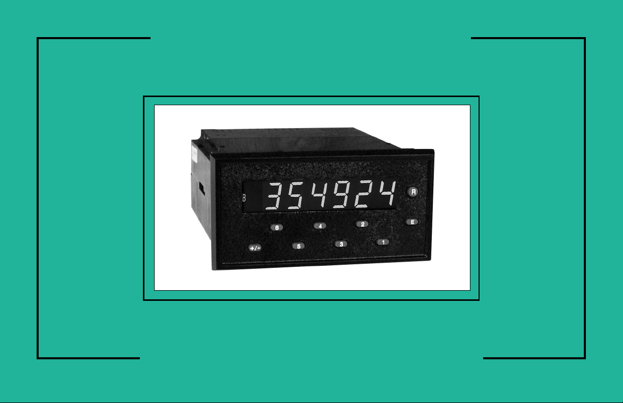
The Gemini 4000 series (4100 & 4200) instruments are two input
microprocessor based dual function counter/rate or dual counter instruments.
The 6-digit display features 0.56" high LEDs with negative sign, overflow and
displayed value indicators (A & B) located to the left of the display. When
programmedas a counter/rate instrument, the Aindicator will be onwhen therate
is displayed and the B indicator will be on when the count is being displayed.
Pushing the “+/-” button toggles the display between the counter and rate or the
two counters depending on the personality selected.
The Gemini 4000 series consists of two basic units, a singlepreset version,the
Gemini 4100, and a two preset version, the Gemini 4200. Each basic unit is also
available in 115/230VAC versions, with orwithout Serial communications and a
relay board. The 20 mA current loop option (serial communications) makes
possible remote or computerized monitoring or control of the Count, Presets and
Scale Factors.
Flexibility and usefulness are insured through user programmability. With
simple front panel keystrokes andrear panel switch settings, any one of a number
of configurations can be selected. Once the selection is made, all or part of the
keyboard can be disabled to protect the settings and guarantee that no unwanted
changes can occur during the measurements.
Each time the power is turned off, the unitautomatically saves the settings and
data in its special no power memory. When power is restored, the Gemini sets
itself back to the operational modes and restores the data it had at power down.
The “no power” E
being applied to and removed from the unit.
Whenever the power comes on, the Gemini performs a series of internal
diagnostics to verify the integrity of the stored data.There isalso a self-test mode
and a “watchdog” timer to help prevent processor lockup.
The Gemini 4000 seriescounters can accept bi-directional, uni-directional, or
quadrature signals. They also have the capability to double or quadruple
(Quadrature x4) the resolution of the incoming count signal. A separate input
mode is available to make the counter/rate or dual counters completely
independent of each other.
One input provides the signal for rate or a counter and the other input provides
the signal for a counter. An anti-coincidence add/subtract mode is also provided
to obtain a difference between two input signals.
Each channel features separate scaling and decimal point placement for
readout in different units or at different resolutions.
2
PROM’s life expectancy is at least 100,000 cycles of power
A Counter Load feature enables the operator to modify the count value under
circumstances that occur when flawed material has been counted and it is
necessary to adjust the countvalue accordingly. The Counter Loadfeature can be
“locked out” in applications where it is not required.
The Rate Indicator portion uses a time interval method (1/tau) to calculate the
rate value.This methodenables high resolution at all rates. The unit countsinput
pulses and after a programmable minimum update time has occurred, it waits
until the next edge occurs, takes the elapsed time and number of edges, and
calculates the rate value. At slower rates, averaging can be accomplished by
programming the “Rate Minimum Update Time” (0.5 sec. to 16 sec.) for the
desired response. Extensive scaling capabilities allow practically any desired
reading at very slow count rates.
For maximum flexibility, the Gemini’s output(s) can be assigned to either the
rate or count channels or one to each. When in dual counter mode, the output(s)
can be assigned to the Counter B channel. For the Gemini 4200, one can be
assigned to Counter A and the other to Counter B.
The relay(s) are mounted on a plug-in board which makes it easy to field
upgrade your Gemini. Thecontacts are ratedfor 240 VAC or28 VDC at 5amps.
The construction of the Gemini features a metal, die cast bezel for maximum
durability with high quality appearance. The sealed front panel meets NEMA
4/IP65 specifications for washdown and/or dust, when properly installed.
Electrical connections are made with removable, plug-in terminal strips at the
rear of the unit. Clamp-type pressure plate terminals accept stripped #14 AWG
wire without lugs.
SAFETY SUMMARY
All safety related regulations, local codes and instructions that appear in the
manual or on equipment must be observed to ensure personal safety and to
prevent damage to either the instrument or equipment connected to it. If
equipment is used in a manner not specified by the manufacturer, the protection
provided by the equipment may be impaired.
Do not usethis unit to directly command motors, valves,or otheractuators not
equipped with safeguards. To do so, can be potentially harmful to persons or
equipment in the event of a fault to the unit.
-2-
Page 5

PROGRAMMING THE GEMINI
When your Gemini arrives from the factory, it has already been programmed
to function as a counter and rate indicator. It is programmed with the factory
settings listed in the “Initial Factory Configuration” section. If it is required to
have the unit operate as two counters, the Unit Personality function code can be
changedtodoso.
The personality, functions, and modes are accessed by pressing the appropriate
keys. A function is defined by a two-digit code which appears on the left sideof the
display. Themode of that function is shown asa one-digit code on theright side of
the display. At times there will be a “-” sign modifier to the left of the mode.
Data for the Presets, Scale Factors, Timed Output Values, and Counter Load
Values are entered differently. Each digit key controls the digit on the display
directly aboveit. Changing the digits can be done by repeatedly pressing the key
beneath the digit position you wish tochange orby holding the key down. Asyou
hold it down, or repetitively press it, the valueof thatdigit willchange cyclically,
counting up to 9, thento 0, and then upagain. The 6 numberedkeys correspond to
the six digits, and the “+/-” key corresponds to polarity.
PROGRAMMING THE PERSONALITY
Entering function and mode is easily accomplished by
pressing theappropriate digitkey. Forthe personality function,
you would enter 41 by pressing the front panel keys 4 and 1.
The digits on the left side of the display show thefunction
code; the digits on the right side show the current
programmed mode.
A mode selection is made by entering a new number. On
some of the entries, you have the option of a plus “+” or minus
“-” sign. In the cases where a “+” sign is required, no sign will
be displayed. If you do enter a “-” sign (using the “+/-” key), a
minus sign will be displayed in front of the appropriate digit.
Pressing the “E” key finalizes the change. The display
will now show the count or rate value immediately.
If you do not press the “E” key, the change will not be
recorded. The display will remain in the programming mode
for 15 seconds, and then return to normal operating mode
using the old functional mode setting.
Whenever the Unit Personality is changed, the factory settings will
automatically be loaded into the unit. The factory settings can also be
programmed into the unit bycalling upthe UnitPersonality, puttinga “-” in front
of the mode by pushing the “+/-” button, and entering it.
Refer to the “Initial Factory Configuration” section for more details.
PROGRAMMING THE PRESET, SCALE FACTORS, TIMED
OUTPUTS & COUNTER LOAD VALUES
The Presets and Scale Factor Values are commonly reprogrammed on a daily
basis. As such, single keystroke access has been provided.
The Gemini has two Scale Factors, one for display A
(Counter A or Rate A), and one for display B (Counter B).
Pressing the “3” key will call up the Scale Factor for the
current display (Rate A/Counter A, or Counter B).
To call up the “other” Scale Factor, the “+/-” key is first pushed to change the
display to the“other” value,then the “3” key ispushed to display the ScaleFactor
for that value.
-3-
Page 6
PROGRAMMING THE PRESET, SCALE FACTORS, TIMED
OUTPUTS & COUNTER LOAD VALUES (Cont’d)
The new value will be entered when the “E” key is
pressed.
Once the Scale Factor is displayed, changing the digits
can beaccomplished byrepeatedly pressingthe keybeneath
the digit position you wish to change or by holding the key
down, allowing the digit to cycle.
The new value will be entered when the “E” key is
pressed.
The internal count value is multiplied by the Scale Factor Value, which
changes the displayed value accordingly. It is important tonote thatthe precision
of an application cannot beimproved by using a ScaleFactor greater than one.To
accomplish greater precision, more pulse information must be generated per
measuring unit. For example, if 5 pulses are being received per foot of material,
the precision of 10th of feet cannot be attained by simply programming a Scale
Factor of 2.0000, even though the display is reading in tenths. In this case, the
display will increment by two for each count input. Thus, if an odd Preset Value
is entered, such as 6.7 ft., the Gemini will alter the Preset display to read in even
tenths of feet.
To display the Preset 1 Value the “1” key is pushed.
To change the value, the digits can be cycled through in
the same manner as discussed for the Scale Factor. The
preset values can range from -999999 to +999999.
The ScaleFactor Value will have a direct effect on the preset being entered (if
assigned to the counter). For Scale Factors greater than one, the preset value
should be an integer multiple of the Scale Factor. If it is not, the Gemini will
automatically adjust the presetvalue up or down to force it to be evenly divisible
by the Scale Factor.
The Timed Output 1 or 2 Value is changed by entering a
two-digit function code. After the code is entered, the
display will show the present Timed Output Value in
seconds with two decimal place resolution. The Timed
Output Values can be set from .01 to 599.99 seconds.
To change the Timed Output 1 Value, enter function code
53 and enter the new value by holding down or repeatedly
pressing the keybelow the digit position youwish to change.
The new value will be entered when the “E” key is pressed.
The display will immediately return to the count value.
Note: ATimed Output Value of zero cannot be programmed into the Gemini.If a
value of 0 is entered into the display and the “E” key is pressed, the unit will
remain in data entry mode.If a new value isnot entered, it will time outand the
unit will continue to use its previous setting.
As with the other functions, you mustpress “E” to record the changes. For the
data entrymodes, if you do not press the“E” key, a time out of 5seconds occurs,
and the display returns to operating mode without any changes to the value. The
only time any change will occur is when the “E” key is pressed.
-4-
Page 7
It is possible to change the counter values of the Gemini. This feature can be
enabled or disabled by the programming of the “Operator Accessible Functions
Modes”, function code 66. The “Counter LoadValue” isnot stored when the unit
is powered down. When the unit is powered up, the Counter Load values for both
counters (if Dual counterpersonality) are resetto zero.Once changed,the values
will be held until the unit is again powered down.
To accessthe Counter Load valuefor thedesired counter;
first, press the “+/-” key, if necessary, so that the display is
indicating the counter value which is to be changed.
Secondly, press the “E” key and while holding it down,
press the “+/-” key.
The Gemini will now display the displayed Counter Load
value. (It will be zero, unless the value had been changed
since the unit was powered up.)
To change the value, press the key under the digit to be
changed as explained previously for the Preset.
To load the value into the counter, press the “E” key.
The display will flash momentarily and will display the
counter with the new value.
-5-
Page 8

INITIAL FACTORY CONFIGURATION DUAL COUNTER FACTORY SETTINGS*
Keys struck Display Description
4,1 41 1 Personality selected as COUNTER/RATE
4,2 42 3 Reset Rate (A) Output(s) & Counter (B)
4,3 43 1 Count with Inhibit
4,4 44 1 Single edge counting (B)
4,5 45 1 Counter B Scale multiplier of 1.0
4,6 46 1 Counter B leading zero blanking and no decimal point
5,1 51 2 Outputs 1 & 2 assigned to Counter (B)
5,2 52 3 Output 1 terminates at Reset, Normal Phase
5,3 0000.10 Timed Output 1 Value of 0.1 Sec
5,4 54 3 Output 2 terminates at Reset, Normal Phase
5,5 0000.10 Timed Output 2 Value of 0.1 Sec
5,6 56 1 Counter (B), manual reset to zero
6,1 61 4 No Rate (A) right hand dummy zeros
6,2 62 1 Rate per Second
6,3 63 1 Rate (A) 0.5 Sec Minimum Update Time
6,4 64 4 Rate (A) Scale multiplier of 1
6,5 65 1 Rate (A) leading zero blanking, no decimal point
6,6 66 1 No functions except Reset enabled
3 01.0000 Scale Factor A (Rate) set to 1.0000
3 01.0000 Scale Factor B (Counter) set to 1.0000
1 000500 Preset 1 set to 500
2 001000 Preset 2 set to 1000
Keys struck Display Description
4,1 41 2 Personality selected as DUAL COUNTER
4,2 42 3 Reset Counters A & B
4,3 43 1 Count with Inhibit
4,4 44 1 Single edge counting (A & B)
4,5 45 1 Counter B Scale multiplier of 1.0
4,6 46 1 Counter B leading zero blanking and no decimal point
5,1 51 2 Outputs 1 & 2 assigned to Counter B
5,2 52 3 Output 1 terminates at Reset, Normal Phase.
5,3 0000.10 Timed Output 1 Value of 0.1 Sec
5,4 54 3 Output 2 terminates at Reset, Normal Phase.
5,5 0000.10 Timed Output 2 Value of 0.1 Sec
5,6 56 1 Counter B, manual reset to zero
6,1 61 1 Counter A, manual reset to zero
6,4 64 1 Counter A scale multiplier of 1
6,5 65 1 Counter A leading zero blanking, no decimal point
6,6 66 1 No functions except Reset enabled
3 01.0000 Scale Factor A set to 1.0000
3 01.0000 Scale Factor B set to 1.0000
1 000500 Preset 1 set to 500
2 001000 Preset 2 set to 1000
* If [41 1] is changed to [41 2], then the factory settings are as shown.
-6-
Page 9

OPERATOR ACCESSIBLE FUNCTIONS WITH
PROGRAMMING DISABLED
(For details on keyboard entry, see preceding section)
One of the important features of the Gemini is the ability to disable
programming. With this ability, accidental bumping of the keys or tampering by
unauthorized personnel can be prevented. However, it may be necessary to allow
reset and certain programming functions, such as Presetand Scale Factor Values,
to be changed in daily operation. The Gemini, through the use of the “Operator
Accessible Functions” Modes can enable these functions even when the “PGM.
DIS.” (Program Disable) terminal is connected to “COMMON”.
The “Operator Accessible Functions” modes are programmed by entering a
two-digit function code (66) and the desired mode. Unlike other function codes,
the mode does not take effect immediately. The “PGM. DIS.” terminal must be
connected to “COMMON” in order for the Gemini to disable programming and
operate as per the mode programmed.
There are six basic “Operator Accessible Functions” Modes available. These
modes enable the following functions.
1. NO FUNCTIONS EXCEPT RESET ENABLED - In this mode, manual
reset is enabled, but none of the programming functions can be changed.
However, the functions can be interrogated.
2. PRESET PROGRAMMING AND RESET ENABLED - Theentirefront
panel is disabled with the exceptions of Preset programmability and manual
reset. All functions can be interrogated.
3. SCALE FACTOR PROGRAMMING AND RESET ENABLED - The
entire front panel is disabled with the exceptions of Scale Factor
programmability and manual reset. All functions can be interrogated.
4. SCALE FACTOR AND PRESET PROGRAMMING, AND RESET
ENABLED - The entire front panel is disabled with the exceptions of Scale
Factor and Preset programmability, and manual reset. All functions can be
interrogated.
5. PRESET AND COUNTER LOAD PROGRAMMING, AND RESET
ENABLED - The entire front panel is disabled with the exceptions of Preset
and Counter Load programmability. All functions can be interrogated.
6. PRESET,SCALE FACTOR AND COUNTER LOADPROGRAMMING,
AND RESET ENABLED - The entire front panel is disabled with the
exceptions of Preset, Scale Factor and Counter Load programmability. All
functions can be interrogated.
All of these modes can be modified with the addition of a “-” sign. The minus
sign disables the manual reset, at the front panel and the remote reset (RST., not
RST.A) terminal, at the rear of the unit.
There is also a rearpanel DIP switch whichpermits disabling of the frontpanel
reset button. This is independent of the rear terminal remote reset, and can be
used in conjunction with any front panel disable mode. The combination of a
manual and remote reset inputs provides a high level of security without
sacrificing flexibility.
DIAGNOSTICS, SELF-TEST, & “WATCHDOG” TIMER
The security of the Gemini is further enhanced by its self-test diagnostic and
“watchdog” timer capabilities.
The diagnostics are concerned with the special, no power memory of the
Gemini. Whenever the power is turned off, all pertinent function settings and
measurements (except the Counter Load values) are automatically saved. When
power is restored, the functions and data are re-instated. This allows you to
program the unit once and not have to re-program it until you wish to use it in
another mode.
When the function codes and data are saved, computations are made with
these values. Theresult ofthese computations is storedin thememory to serve as
a check against possible error. On power up the same computations are repeated
on the stored data. If the results do not agree with the stored results, a “P” will
appear onthe leftside of the display. If this occurs, refer to the “Troubleshooting
Guide” for directions.
-7-
Page 10

DIAGNOSTICS, SELF-TEST, & “WATCHDOG” TIMER [Cont’d]
Another error indicator is the “watchdog” timer. In order to insure the
software is functioning properly, the program constantly monitors itself. If the
proper sequenceand timing of internal events does not occur, an “E” will appear
on the left side of the display.If this occurs, refer tothe “TroubleshootingGuide”
for directions.
The final type of built-in error checking is the front panel initiated self-test. It
can be performed at any time, even when the Gemini is running. It will not
interfere with theaccumulation of countsor controlfunctions. Afunction code of
“6”, “+/-” starts the test. At this time, whatever was displayedwill disappear and
be replaced by a string of decimal points and the overflow indicator. Then the
display will showa string of 9’s, then 8’s etc., until a string of0’s are shown. The
self-test willthen turn off the overflow indicator and activate the minus “-” sign.
Then the unit shows an interlace pattern of -010101, then -212121, followed by
232323 etc., until -898989 is reached. At this time the outputs can be tested by
pressing the “1”or “2”key. (Theprogram disable terminal must be disconnected
in order to allow activation of the outputs. Also, when testing the output, use
caution, so as not to cause any undesirable or hazardous conditions in the
system.) An automatic exit will takeplace after six seconds or immediately if the
Program Disable terminal is connected to common. Normal length of display
time for each of the patterns is approximately 0.5 sec. Rapidly pressing “E”
during self-test can speed up the sequence.
INPUT CIRCUITRY & SET-UP
There are two independent input channels on the Gemini. Various types of
sensor outputs can be accommodated by appropriate DIP switch set-up. These
include: TTL or CMOS logic, current sinking, current sourcing, or dry contact
and more.
Channel 1 consists of a logic input and a separate low level magnetic pickup
input.
Channel 2 is a completely independent count or control input channel. Like
Channel 1, it can be programmed with DIP switches for a wide variety of logic
inputs, and is identical to Channel 1 in this regard. For a complete detailed
description of input set-up, see Appendix “A”.
OVERFLOW INDICATION
The Gemini features an overflow indicator (LED) which is located to the left
of thesixth digit and above the polarity annunciator. This LEDwill turn on if the
capacity of the display (6-digits) is exceeded or if the internal count capacity
(9-digits) is exceeded. Use of extremely small scale multiplier and Scale Factor
Values can cause the internal count capacity to overflow before the displayed
value would overflow. It should also be noted that the use of Right Hand Dummy
Zeros or Scale Factors larger than one could cause the displayed value to
overflow before a value of 999,999 (6-digits) is accumulated.
When the capacity of the display is exceeded, the count value will be
maintained and will be valid.But ifthe internal count value is exceeded, thenthis
value may no longer be valid.
The overflow LED can also turn on under certain conditions when the rate
input frequencyexceeds the maximum 3250 cps allowedfor a rate update period
of 16 sec. See Code 63 - “Rate Minimum Update Time”.
-8-
Page 11

PROGRAMMING INSTRUCTIONS FOR THE COUNTER/RATE VERSION OF THE GEMINI 4000
The first part of this section provides detailed descriptions of the function
command codes for inputs response modes, reset modes, output terminations,
etc. Then, using an actual application example, the programming instructions for
a Counter/Rate version will be “walked through”, to give the user a full
understanding of the Gemini programming procedure. The descriptions below
give the function command code first, followed by the individual mode
identifier. The Function Command Code Summary in the appendix, lists all
codes. (Only commands and modes pertaining to the Counter/Rate personality
will be discussed in this section.)
CODE 41 - UNIT PERSONALITY
The Gemini can be programmed to operate in one of two different
personalities. In each of the two unit personalities,the Gemini operates as a dual
function indicator. The personality selected determines whether display channel
A will indicate rate or count. In both personalities, display channel B operates as
a counter.
When the Unit Personality is changed and entered, all modes and data values
(Preset, Scale Factors, function codes etc.) will be automatically loaded with the
factory settings for that personality. If, for any reason during programming, it is
desired to return to the factory settings (while in code 41), the “+/-” key can be
pushed. When the “E” key is pressed the unit will load the factory settings into
the Gemini.
The programming procedure willvary for the two unit personalities. This entire
section deals with the unit programmed as a Counter/Rate indicator, [41 1].
[41 1] COUNTER(B)/RATE (A)- In thismode, display channelA functionsas
a rate indicator and display channel B functions as a counter. See the
“PROGRAMMING INSTRUCTIONS FOR THE GEMINI 4000” section
for details.
[41 2] DUAL COUNTER - In this mode, both display channels, A & B, function
as counters.
CODE 42 - RESET BUTTON & TERMINAL ACTUATION MODES
The “Reset Button & Terminal Actuation Modes” controls the affect that the
reset button and terminal have on the two display channels. Resetting will not
affect the rate display in any manner. If the output(s) is assigned to the rate
channel, activating the reset button or terminal will reset the rate output(s) if that
particular response mode is programmed. Resetting counter (B)will alwaysreset
the assigned output(s).
There is a separate “RST. A” terminal, which resets the Rate (A) output when
activated (if output(s) is assigned to rate). It is provided to allow independent
resetting of each channel.
[42 1] RESET RATE (A) OUTPUT(S)
[42 2] RESET COUNTER (B)
[42 3] RESET RATE (A) OUTPUT(S) AND COUNTER (B)
CODE 43 - INPUTS1&2RESPONSE MODES
The Gemini has six different input response modes. They are: Count(1) with
Inhibit(2); Count(1) with Up/Down Control (2); Two input anticoincidence
Add(1)/Subtract(2); Separate Inputmode; Quadrature;and Quadrature x4. In all
modes, except [43 4], Input 1 is used by both the counter and rate channels.
[43 1] COUNT WITH INHIBIT- Input 1 serves asthe count and rate input.Input
2 serves as the Inhibit input. When Input 2 is low, the counter will ignore the
count signal appearing at Input1. The rate channel, however, will continue to
indicate the rate of the signal on Input 1.
When Input 2 is ata high level, thesignal appearing on Input 1 willbe counted.
The “Counter (B) Reset Modes” will determine the count direction. In
applications where the Inhibit function is not actually used, the Input 2
“SRC/SNK” position of the “INPUT CONFIGURATION DIP SWITCH”
should be set to the “SNK” position to provide a 7.8 Kohm pull-up resistor.
This will set Input 2 to the Non-Inhibit state.
-9-
Page 12

CODE 43 - INPUTS1&2RESPONSE MODES [Cont’d]
[43 2] COUNT WITH UP/DOWN CONTROL - In this mode, count direction
can be controlled by thesecond input. Input 1serves as the countand rate input
and Input 2 serves as the direction control signal input. When Input 2 is at a
high level, thecounter will count up. WhenInput 2 is ata low level, thecounter
will count down. The rate is not affected by the directional control Input 2.
[43 3] TWO INPUT ANTI-COINCIDENCE ADD/SUBTRACT - This mode
effectively separates count pulses which may simultaneously appear at the
two inputs. The Gemini unit processes the count pulses into a string of
time-separated pulses, so the internal counter will not lose any count pulses.
Input 1 serves as the add and rate input (count increments) and Input 2 serves
as the subtract input (count decrements).
[43 4] SEPARATE INPUT - In this mode, the two functions, Counter (B) and
Rate (A) are independently controlled bythe inputs.Input 1 serves as the Rate
(A) input and Input 2 serves as the Counter (B) input.
[43 6] QUADRATURE TIMES 4 - This mode takes the quadrature mode, with
two edge counting, one step further. In quadrature times 4, both Input 1 and
Input 2serve as the count or quadrature input, dependingon their state. In one
instance, Input 1 will serve as the count input and Input 2 will serve as the
quadrature input.In another instance, Input 1 will be the quadrature input and
Input 2 will be the count input. This enables each edge, positive and negative
going, of both inputs, 1 and 2, to be counted. This results in a resolution four
times greater than in the basic quadrature x1 mode. As in the other modes,
Input 1 is also used for the rate input. The rate indicator will only use the
falling edge of the Input 1 signal, due to the method of rate indication used.
CODE 44 - COUNTER (B) NUMBER OF COUNT EDGES
The counter of the Gemini can be programmed for either single or two edge
(x2) counting. The number of count edges cannot be set when the count mode is
programmed for quadrature x4 operation. The Gemini will ignore any attempt to
enter function command code 44 when set for quadrature x4.
[43 5] QUADRATURE COUNTING - Quadrature counting modes are
primarily used inpositioning and anti-jitterapplications. The reason this mode
works is due to the manner in which two pickups are positioned relative to
each other. The signal on Input 2 is a pulse train signal shifted 90° away from
the Input 1signal. These twosignals are processed by theGemini asfollows:
Input 1 serves as the count and rate input, while Input 2 serves as the
quadrature input. For quadrature with single edge counting, the counter will
count ina positive direction when Input 1 is a negative going edgeand Input 2
is ata low level. The counter will count in a negative direction when Input 1 is
a positive going edge and Input 2is at a low level. Alltransitions onInput 1 are
ignored when Input 2 is at a high level. These logic rules provide the basis for
anti-jitter operation which will prevent false counts from occurring due to
back-lash, vibration, chatter, etc.
When twoedge counting is used, the quadrature mode works the same as with
single edge counting when Input 2 is low. But when Input 2 is at a high level,
counts at Input 1 are no longer ignored. Instead the logic rules for Input 1 are
complemented, allowing both edges of Input 1to becounted. This doubles the
effective resolution of the encoded input. The rate indicator will only use the
falling edge of the Input 1 signal, due to the method of rate indication used.
[44 1] SINGLEEDGE COUNTING (x1) - The unitcounts onthe negativegoing
(falling) edgeof the count input signal.The count mode descriptions describe
how each mode uses this method of edge counting.
[44 2] TWO EDGE COUNTING (x2) - This mode is used when doubling of the
count signal input is required. The unit counts on the positive going (rising)
edge of the count input signal, as well as, the negative going (falling) edge.
-10-
Page 13

CODE 45 - COUNTER (B) SCALE MULTIPLIER
There are four Counter B Scale Multipliersthat areavailable. They effectively
divide the internal Count B value by 1, 10, 100, and 1000 respectively, to yield
the displayed Counter B value. Note: Use of a small scale multiplier in
conjunction with a small Scale Factor could cause the internal count value to be
exceeded before the 6-digit display value is exceeded. See “Programming the
Presets, Scale Factors, Timed Outputs & Counter Load Values” section for
more details.
[45 1] x1
[45 2] x0.1
[45 3] x0.01
[45 4] x0.001
CODE 46 - COUNTER (B) DECIMAL POINT & LEADING
ZERO BLANKING
There are six basic modes of decimal point placement for the counter of the
Gemini. The decimal point is placed to the right of the display digit that
corresponds to the mode identifier. (The right most decimal point, digit 1, is
never turned on.) A “-” sign in front of the mode identifier will inhibit leading
zero blanking. The absence of a “-” sign will enable leading zero blanking.
[46 1] 0
[46 2] 0.0
[46 3] 0.0 0 LEADING ZERO
[46 4] 0.0 0 0 BLANKING
[46 5] 0.0000
[46 6] 0.00000
[46 -1] 000000
[46 -2] 00000.0
[46 -3] 0 0 0 0.0 0 LEADING ZERO
[46 -4] 0 0 0.0 0 0 BLANKING INHIBITED
[46 -5] 00.0000
[46 -6] 0.00000
CODE 51 - OUTPUT ASSIGNMENT
The output(s) of the Gemini 4000 can be assigned to either the rate or count
channel. Assigning the output(s) to the rate [51 3] will automatically configure
the “Counter (B) Reset Mode” to Reset to Zero, [56 1].
The Gemini 4200 has a Preset tracking feature which allows Preset 1 to track
Preset 2. If Preset tracking is programmed, whenever the Preset 2 value is
changed, the Preset 1 value will also change to maintain the same offset. For
example, if Preset 1 is 100 and Preset 2 is 200, changing Preset 2 to 300 will
automatically change Preset 1 to 200, maintaining same 100 unit offset. In order
to changethe amount of offset, the Preset 1 value is changed.The Preset tracking
feature is programmed by adding a “-” modifier in front of the desired mode.
[51 1] OUTPUT 1 ASSIGNED TO RATE (A), OUTPUT 2 TO COUNTER
(Gemini 4200 only)
[51 2] OUTPUTS 1 & 2 ASSIGNED TO COUNTER (B)
[51 3] OUTPUTS 1 & 2 ASSIGNED TO RATE (A)
[51 -1]
[51 -2]
[51 -3]
These modes are identical with the exception
that Preset Tracking is enabled.
CODE 52 - OUTPUT 1 TERMINATION MODES
The Gemini has six “Output 1 Termination Modes” which control the way
Output 1 will terminate or reset. In all modes, Output 1 will terminate
immediately when the channel to which it is assigned is manually reset.
For the Gemini 4200, the Output 1 termination modes 1 & 2 are available only
when both outputs are assigned to the Counter (B), [51 2].
A reverse phase mode is available on the Gemini. This refers to the
complementing of the logic state of the output. With normal phase operation,
when the display value reaches Preset 1, Output 1 will turn on. The reset
condition of Output1 isoutput off.In reversephase operation,Output 1turns off
when the Preset 1 Valueis reached. The reset condition of Output 1 is output on.
(Note: The state of the relay, if used, is also reversed.) A “-” sign in front of the
mode identifier will provide for reverse phase operation. The absence of a “-”
sign will indicate normal phase operation.
-11-
Page 14

CODE 52 - OUTPUT 1 TERMINATION MODES (Cont’d)
[52 1] TERMINATE AT OUTPUT 2 START - Output 1 will terminate when
Output 2 starts.Output 1is setfor normal phaseoperation. (Gemini 4200Only)
[52 2] TERMINATE AT OUTPUT 2 END - Output 1 will terminate when
Output 2 ends.Output 1 isset for normalphase operation. (Gemini 4200 Only)
[52 3] TERMINATE AT MANUAL RESET - Output 1 activates when the rate
or count, whichever it is assigned to, is greater than or equal to the Preset 1
Value. Inthis mode,once Output 1 is activated, it does not deactivateuntil the
moment a reset occurs. Output 1 is set for normal phase operation.
[52 4] TERMINATE AT MANUAL RESET END - This mode is like the
preceding, except Output 1 deactivates when reset ends. Output 1 is set for
normal phase operation.
[52 5] TERMINATE AFTER TIMED OUTPUT 1 - Once Output 1 has been
activated, it will deactivate after the predetermined length of time (code 53)
has expired. Manual reset will override the timed output and reset Output 1.
Output 1 is set for normal phase operation.
When Output 1 alone is assigned to the rate [51 1], the output will activate
when therate isgreater than or equal to the Preset 1 Value. When bothoutputs
are assigned to Rate [51 3], Output 1 will act as an “underspeed” detect. Itwill
activate when the rate is less than or equal to the Preset 1 Value. Output 1 will
activate every update time period for which the above conditions are true. If
the Timed Output 1 Value, code 53, is greater than the rate update time, the
output will appear to belatched on,deactivating when the rate dropsbelow the
Preset and the output time expires.
output again deactivates. When Output 1 is assigned to the counter and the
Preset 1 value is changed, Output 1 will immediately go to the proper state.
Upon power up, Output 1,if assigned to CounterB, will“remember” itspower
down boundary condition and go to that state. Output 1 is set for normal
phase operation.
[52 -1]
[52 -2]
[52 -3] These modes are the same as above with the exception
[52 -4] that the output is set for reverse phase operation.
[52 -5]
[52 -6]
CODE 53 - TIMED OUTPUT 1 VALUE
The Gemini has the capabilityof varying the Timed Output 1 Value from 0.01
second to 599.99 seconds. When the code is entered, instead of a single mode
identifier digitbeing displayed, six digits will be shown. Refer to “Programming
the Presets, Scale Factors, Timed Outputs & Counter Load Values” section for
more details about entering. The timed output will be terminated if the unit is
manually reset.
The Timed Output 1 Value is used only when in Timed Output 1 Termination
mode, [52 5].
Note: ATimed Output Value of zero cannot be programmed into the Gemini.If a
value of 0 is entered into the display and the “E” key is pressed, the unit will
not enter the 0, but will stay in the data entry mode. If a new value is not
entered, it willtime out and the unitwill continueto use its previoussetting.
[52 6] BOUNDARY MODE - When in boundary mode, the Preset 1 Value
serves as the boundary point. When the display value (count or rate) is less
than the Preset 1 Value, Output 1 is not activated (normal phase). When the
display value is greater than or equal to the Preset 1 Value, Output 1 is
activated. If the display value were to drop below Preset 1, Output 1 would
then deactivate.For negative Preset points, Output 1 is not activated when the
count value is more positive than the Preset 1 Value. When the count is more
negative than (only possible with counter) or equal to Preset 1, Output 1 is
activated. If the count becomes more positive than the Preset 1 Value, the
CODE 54 - OUTPUT 2 TERMINATION MODES (GEMINI 4200
Only)
The Gemini 4200 has six “Output 2 Termination Modes” which control the
way Output 2 will terminate or reset. In all modes, Output 2 will terminate
immediately when the channel to which it is assigned is manually reset.
Output 2 termination modes 1 & 2 are available only when both outputs are
assigned to the Counter (B), [51 2].
-12-
Page 15

A reverse phase mode is available on the Gemini 4200. This refers to the
complementing of the logic state of the output. With normal phase operation,
when the display value reaches Preset 2, Output 2 will turn on. The reset
condition of Output2 isoutput off.In reversephase operation,Output 2turns off
when the Preset 2 Valueis reached. The reset condition of Output 2 is output on.
(Note: The state of the relay, if used, is also reversed.) A “-” sign in front of the
mode identifier will provide for reverse phase operation. The absence of a “-”
sign will indicate normal phase operation.
negative than (only possible with counter) or equal to Preset 2, Output 2 is
activated. If the count becomes more positive than the Preset 2 Value, the
output again deactivates. When Output 2 is assigned to the counter and the
Preset 2 value is changed, Output 2 will immediately go to the proper state.
Upon power up, Output 2,if assigned to CounterB, will“remember” itspower
down boundarycondition andgo to that state. Output 2 is set for normal phase
operation. Programming Boundary mode will automatically select [56 1], if
[51 1 or 2] is programmed.
[54 1] TERMINATE AT OUTPUT 1 START - Output 2 will terminate when
Output 1 starts. Output 2 is set for normal phase operation.
[54 2] TERMINATE AT OUTPUT 1 END - Output 2 will terminate when
Output 1 ends. Output 2 is set for normal phase operation.
[54 3] TERMINATE AT MANUAL RESET - Output 2 activates when the rate
or count, whichever it is assigned to, is greater than or equal to the Preset 2
Value. Inthis mode,once Output 2 is activated, it does not deactivateuntil the
moment a reset occurs. Output 2 is set for normal phase operation.
[54 4] TERMINATE AT MANUAL RESET END - This mode is like the
preceding, except Output 2 deactivates when reset ends. Output 2 is set for
normal phase operation.
[54 5] TERMINATE AFTER TIMED OUTPUT 2 - Once Output 2 has been
activated, it will deactivate after the predetermined length of time (code
55) has expired. Manualreset will overridethe timed output andreset Output
2. When assigned to count or rate, Output 2 will activate when the display
value is greater than orequal tothe Preset 2 Value. Output 2 is set for normal
phase operation.
[54 6] BOUNDARY MODE - When in boundary mode, the Preset 2 Value
serves as the boundary point. When the display value (count or rate) is less
than the Preset 2 Value, Output 2 is not activated (normal phase). When the
display value is greater than or equal to the Preset 2 Value, Output 2 is
activated. If the display value were to drop below Preset 2, Output 2 would
then deactivate.For negative Preset points, Output 2 is not activated when the
count value is more positive than the Preset 2 Value. When the count is more
[54 -1]
[54 -2]
[54 -3] These modes are the same as above with the exception
[54 -4] that the output is set for reverse phase operation.
[54 -5]
[54 -6]
CODE 55 - TIMED OUTPUT 2 VALUE (GEMINI 4200 Only)
The Gemini 4200 has thecapability of varying the TimedOutput 2Value from
0.01 second to 599.99 seconds. When the code is entered, instead of a single
mode identifier digit being displayed, six digits will be shown. Refer to
“Programming the Presets, Scale Factors, Timed Outputs & Counter Load
Values” section for more details about entering. The timed output will be
terminated if the unit is manually reset.
The Timed Output 2 Value is used only when in Timed Output 2 Termination
mode, [54 5].
Note: A Timed Output Value of zero cannot be programmed into the Gemini
4200. If a value of 0 is entered into thedisplay and the “E” key is pressed, the
unit will not enter the 0, but will stay in the data entry mode. If a new value is
not entered itwill time out and theunit willcontinue to use itsprevious setting.
-13-
Page 16

CODE 56 - COUNTER (B) RESET MODES
The Gemini 4000 has six different counter reset modes. There are also two
methods by which manual resetcan acton thecounter (reset must be enabled, see
function code 66 and dip switch set-up). The first is a “maintained” reset action,
where the unit is held at reset for as long as the reset terminal or reset button is
activated. The second is a“momentary” reset, in which theunit resets, when reset
is activated, and starts counting even though the terminal or resetbutton may still
be active. A “-” sign in front of the mode identifier indicates “momentary” reset
action, the absence of the “-” sign indicates “maintained” reset action.
For the Gemini 4200, if both outputs are assigned to the Rate Channel [51 3],
or the Output 2 Termination modeis boundary[54 6], theonly Counter (B) Reset
mode that is available is Reset to Zero [56 1].
In Reset to Zero modes the Output (if assigned to Counter B) activates at the
Preset Value. In Reset to Preset modes the Output activates at zero.
In the “Reset to Preset” modes, for proper operation, the counter normally
counts down. In the “Count with Inhibit” and “Separate Inputs” input response
modes, [43 1 or 4], the unit will automatically count down if a Reset to Preset
mode is selected. In the other input response modes, proper input phasing is
required for down counting. See “CODE 43 - INPUTS 1 & 2 RESPONSE
MODES” section for more details.
[56 3] AUTOMATIC RESET TO ZERO AFTER TIMED OUTPUT - The
counter automatically resets to zero when Timed Output ends. Manual reset
is “maintained” and will override automatic reset. The “Output Termination
Mode” should be programmed for timed output operation, [54 5], when in
this mode.
[56 4] AUTOMATIC RESET TO PRESET AFTER TIMED OUTPUT - The
counter automatically resets to Preset when Timed Output ends. Manual reset
is “maintained” and will override automatic reset.
The “Output Termination Mode” should be programmed for timed output
operation, [54 5], when in this mode.
[56 5] AUTOMATIC RESET TO ZERO AT BEGINNING OF TIMED
OUTPUT (AT PRESET) - In this reset mode, the counter will automatically
reset to zero at the beginning of Timed Output (at Preset). The Timed Output
Value must be shorter than the time required for the counter to count to the
Preset Value,otherwise, the Output will appear to be latched on.Manual reset
is “maintained” and will override automatic reset. The “Output Termination
Mode” should be programmed for timed output operation, [54 5], when in
this mode.
Note: The Reset Button & Terminal Actuation Mode must be programmed to
mode [42 2 or 3] in order to be able to manually reset the Counter (B). The
activation and de-activation response time for reset is 10 msec.
Note: For the Gemini 4200, all reset to preset modesreset to preset 2 and Timed
Output refers to Output 2.
[56 1] MANUAL RESET TO ZERO (RTZ) - Manual reset to zero is
accomplished by pulling the “RST.” terminal to “COMMON” or, if the front
panel reset is enabled, by pressing the front panel reset button. Reset is
“maintained”.
[56 2] MANUAL RESET TO PRESET (RTP) - Manual reset to Preset is
accomplished by pulling the “RST.” terminal to “COMMON” or, if the front
panel reset is enabled, by pressing the front panel reset button. Reset is
“maintained”.
[56 6] AUTOMATIC RESET TO PRESET AT BEGINNING OF TIMED
OUTPUT (AT ZERO) - Inthis reset mode,the counterwill automaticallyreset
to Presetat the beginning of Timed Output (at zero). The Timed Output Value
must be shorter than the time required for the counter to count to zero,
otherwise, the Output will appear to be latched on. Manual reset is
“maintained” and will override automatic reset. The “Output Termination
Mode” should be programmed for timed output operation, [54 5], when in
this mode.
[56 -1]
[56 -2]
[56 -3] These modes are the same as above with the exception
[56 -4] that manual reset is set for “momentary” operation.
[56 -5]
[56 -6]
-14-
Page 17

CODE 61 - RATE (A) RIGHT HAND DUMMY ZEROS
Dummy zeros can be used to alleviate display fluctuations due to an unstable
input signal. These zeros effectivelymove significantdigits tothe left. Therefore,a
normal count of 1 could be shown as a 10, 100, or 1000. Using the dummy zeros
will make it necessary to adjust the scaling if they were not considered before.
[61 1] 1 RIGHT HAND DUMMY ZERO
[61 2] 2 RIGHT HAND DUMMY ZEROS
[61 3] 3 RIGHT HAND DUMMY ZEROS
[61 4] NO RIGHT HAND DUMMY ZEROS
CODE 62 - RATE CONVERSION FACTOR
The rate conversion factor provides a simple means of obtaining thedesired rate
reading, usingthe sameScale Factor Value as the counter, when the rateand count
units are the same. In most applications, it is simply programmed to the desired
time unit that the rate is to displayed in. See Appendix “F” - Scaling For Rate.
[62 1] Rate Per Second (x1)
[62 2] Rate Per Minute (x60)
[62 3] Rate Per Hour (x3600)
CODE 63 - RATE MINIMUM UPDATE TIME
The determination of the rate value uses a method in which the elapsed time is
measured between the first and last pulse of the update period. The minimum
update time is the shortest the timeperiod canbe. Once the minimum updatetime
has expired, the unit will end the measurement period when the next negative
going count edge occurs. If the unitdoes notreceive the next negative count edge
within the maximum update time at the start of the measurement period, the unit
will end the time period and the rate display will go to zero. At very slow count
rates the update time period will be the actual period of one count cycle.
[63 1] 0.5 Sec. minimum/1 Sec. maximum
[63 2] 1 Sec. minimum/2 Secs. maximum
[63 3] 2 Sec. minimum/4 Secs. maximum
[63 4] 4 Sec. minimum/8 Secs. maximum
[63 5] 8 Sec. minimum/16 Secs. maximum (max. rate = 7500 cps)
[63 6] 16 Sec. minimum/32 Secs. maximum (max. rate = 3250 cps)
CODE 64 - RATE SCALE MULTIPLIER
The Rate Scale Multiplier is used in conjunction with the Rate Scale Factor A
and Rate Conversion Factor to scale the actual signal input to obtain the desired
reading. See Appendix “F” - Scaling For Rate.
[64 1] x 1000
[64 2] x 100
[64 3] x10
[64 4] x1
[64 5] x0.1
[64 6] x0.01
CODE 65 - RATE (A) DECIMAL POINT & LEADING ZERO
BLANKING
There aresix basicmodes ofdecimal pointplacement forthe Rateindicator of
the Gemini. The decimal point is placed to the right of the display digit that
corresponds to the mode identifier. (The right most decimal point, digit 1, is
never turned on.) A “-” sign in front of the mode identifier will inhibit leading
zero blanking. The absence of a “-” sign will enable leading zero blanking.
[65 1] 0
[65 2] 0.0
[65 3] 0.0 0 LEADING ZERO
[65 4] 0.0 0 0 BLANKING
[65 5] 0.0000
[65 6] 0.00000
[65 -1] 000000
[65 -2] 00000.0
[65 -3] 0 0 0 0.0 0 LEADING ZERO
[65 -4] 0 0 0.0 0 0 BLANKING INHIBITED
[65 -5] 00.0000
[65 -6] 0.00000
-15-
Page 18

CODE 66 - “OPERATOR ACCESSIBLE FUNCTIONS” MODES
The Gemini has six basic levels of “Operator Accessible Functions”. Each of
these levels can be modified to enable or disable manual reset. When the “PGM.
DIS.” (Program Disable) terminal is connected to “COMMON”, access to all
functions is disabled except forthose listed below whichwill remain enabled.All
of the function codes and parameters can be interrogated, regardless of the
“Operator Accessible Functions” mode selected.
A “-” sign in front of the mode identifier will disable the front panel Reset
button and the “RST.” terminal.
Note: The front panel reset button can be independently disabled by using the
disable reset DIP switch.
[66 1] NO FUNCTIONS ENABLED EXCEPT RESET - In this mode, manual
reset is enabled, but none of the programming functions can be changed.
[66 2] PRESET PROGRAMMING AND RESET ENABLED - In this mode,
manual reset and the programming of the Preset Values are enabled.
[66 3] SCALE FACTOR PROGRAMMING AND RESET ENABLED - In this
mode, manual resetand the programming of the Scale FactorValues are enabled.
[66 4] SCALE FACTOR, PRESET PROGRAMMING AND RESET
ENABLED - In this mode, manual reset and the programming of the Scale
Factor and Preset Values are enabled.
[66 5] PRESET, COUNTER LOAD PROGRAMMING AND RESET
ENABLED - In this mode, manual reset and the programming of the Presets
and Counter Load Value are enabled.
[66 6] PRESET, SCALE FACTOR, COUNTER LOAD PROGRAMMING
AND RESET ENABLED- In thismode, manual resetand the programming of
the Presets, Scale Factors and Counter Load Value are enabled.
[66 -1]
[66 -2]
[66 -3] These modes are the same as above with the
[66 -4] exception that manual reset is disabled.
[66 -5]
[66 -6]
PRESET VALUE
Whenever the display value equals the preset value (when output is assigned
to that display channel), an output action will occur. This action depends on the
previously programmed modes. The preset values may range from -999,999 to
999,999. (Refer to “Programming the Presets, Scale Factors, Timed Outputs &
Counter Load Values” section for instructions on entering the preset values.)
The Counter (B)Scale Factor, SFB,will have a direct effecton the preset value
being entered (if assigned to the counter). For a Scale Factor Value greater than
one, thepreset valueshould be an integer multiple of the Scale Factor. If itis not,
the Gemini will automatically adjust the preset value up or down to force it to be
evenly divisible by the Scale Factor.
“1” - PRESET 1 VALUE
“2” - PRESET 2 VALUE (GEMINI 4200 Only)
SCALE FACTORS A & B
“3” SCALE FACTOR - The Scale Factor, for which value (count or rate) is
currently being displayed, is accessed by pressing the “3” key. To access the
Scale Factor of the “other” display value, the “+/-” key would be pushed (to
change the display to the other value), then the “3” key would be pushed.
The number of pulses counted (internal count value) is multiplied by the Scale
Factor, which changes the displayed value accordingly. A Scale Factor Value of
1.0000 would result in a display of the actual number of input pulses that have
been counted. The Scale Factor is used primarily for conversion from existing
pulses per unit of measure to the required displayed units. This includes
conversion from different units of measure (i.e feet to meters, etc.).
The Scale Factor Values may range from -5.9999 to +5.9999 (positive onlyfor
Rate (A) Scale Factor, SFA). Refer to “Programming the Presets, Scale Factors,
Timed Outputs & Counter Load Values” section for entering instructions. It is
important to note that the precision of a counter application cannot be improved
by using a Scale Factor greater than one. To accomplish greater precision, more
-16-
Page 19

pulse information must be generated per measuring unit. For example, if 5 pulses
are being received per foot of material, the precision of 10th of feet cannot be
attained by simply programming a Scale Factor of 2.0000, even though the
display is reading in 10ths.In this case, thedisplay will incrementby twofor each
count input. Thus if an odd Preset Value was entered, such as 6.7 ft., the Gemini
will alter the preset to read in even tenths of feet.
Note: Use of a small Scale Factor in conjunction with a small scale multiplier
could cause the internal count value (counter) to be exceeded before the
6-digit display value is exceeded.
COUNTER LOAD VALUE
The Counter Load Value is provided to allow the user to modify the count
value. The Counter Load Value is reset to zero when the Gemini is powered up.
Once the Counter Load Value has been changed, it will remain set to that value
until the unitis powereddown andup. Accessingthe CounterLoad Valuefor the
counter that is currently being displayed is accomplished by pushing the “E”
button, and while holding it down, also pushing the “+/-” button. See
“Programming the Presets, Scale Factors, Timed Outputs & Counter Load
Values” section for entering instructions.
“E” & “+/-” - Counter Load Value for the currently displayed counter.
-17-
Page 20
DUAL PRESET COUNTER & RATE APPLICATION
A wire screen manufacturer requires a cut to length system, and in addition, a
prewarning of an overspeed condition. The cutting machine is equipped with an
existing 12 tooth gear, driving a one foot circumference feed roller.
The Gemini 4200’s counter is to read in feet. When 15,000 feet has been
accumulated on thetake uproll, the counter outputis to turn onand deactivatethe
drive system. The operator will then make the cut, load a new take up roll and
reset the Gemini to start a new roll.
In addition to cut to length, the same Gemini 4200 is to be used to indicate the
speed of the wire screen in feet per minute, while providing a “overspeed”
warning. The normal running speed of the material is 225 feet per minute. The
maximum allowable speed of the process is 250 feet per minute.
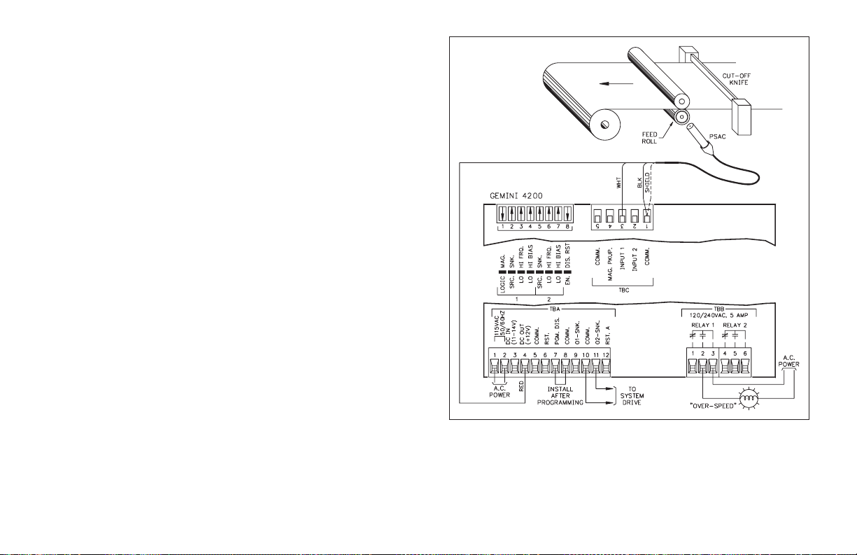
HARDWARE SETUP
The accompanying drawing shows how the hardware is setup for this
application. A Model PSAC proximity sensor is used to sense the teeth on the
gear. The application does not require bi-directional counting, so the Gemini
4200 will be programmed for the Count with Inhibit “Inputs 1 & 2 Response
Mode”. In this mode, both the rate indicator and counter will utilize the same
input signal. The switch settings and the wiring connections are as shown. The
Input 2 switch positions 5-7 are setto put the Input 2 in the non-inhibit state with
maximum noise immunity.
SCALING THE COUNTER
In order to scale the counter, the procedure and formulas in Appendix “E” Scaling for Counting are used.
In converting pulse units to “Display Units”, it is known that 12 pulses are
equivalent to 1 revolution of the feed roll, which is equivalent to 1 foot linear
travel of the wire screen.The “Display Unit”, therefore is 1 foot and the“Number
of Pulses” per display unit is 12.
STEP 1 - Calculate the Total Scaling Factor, “K
Appendix “E”.
K
= Display Unit / Number of Pulses
T
K
= 1/12 = 0.083333
T
”, using Formula #1 of
T
STEP 2 - Determine the Number of Count Edges, “NCE”, necessary for this
application, and calculate the Remaining Scaling required, “K
Formula #2 of Appendix “E”.
Since the Total Scaling Factor, “K
be used, therefore, the Number of Count Edges, “NCE”, is 1.
K
= 0.083333/1 = 0.083333
R
”, is less than 1, single edge counting can
T
K
/NCE
R=KT
”, using
R
-18-
Page 21

STEP 3 - Determine the Scale Multiplier Value, “SCM”, and calculate the Scale
Factor, “SF”, using Formula #3 of Appendix “E”.
A Scale Multiplier value of 0.1 is chosen to provide the maximum number of
significant digits in the Scale Factor.
SF = K
/SCM
SF = 0.083333/0.1 = 0.8333
R
SCALING THE RATE INDICATOR
In this application the rate indicator can be programmed with the same scale
factor and scalemultiplier values asobtained whenscaling the counter. The only
other scaling that would be required is choosing the proper Rate Conversion
Factor, to obtain the displayin the desired timeunits. The application callsfor the
rate to be indicated in feet per minute, therefore, the Rate Per Minute Rate
Conversion Factor is selected.
STEP BY STEP PROGRAMMING OF THE GEMINI 4200
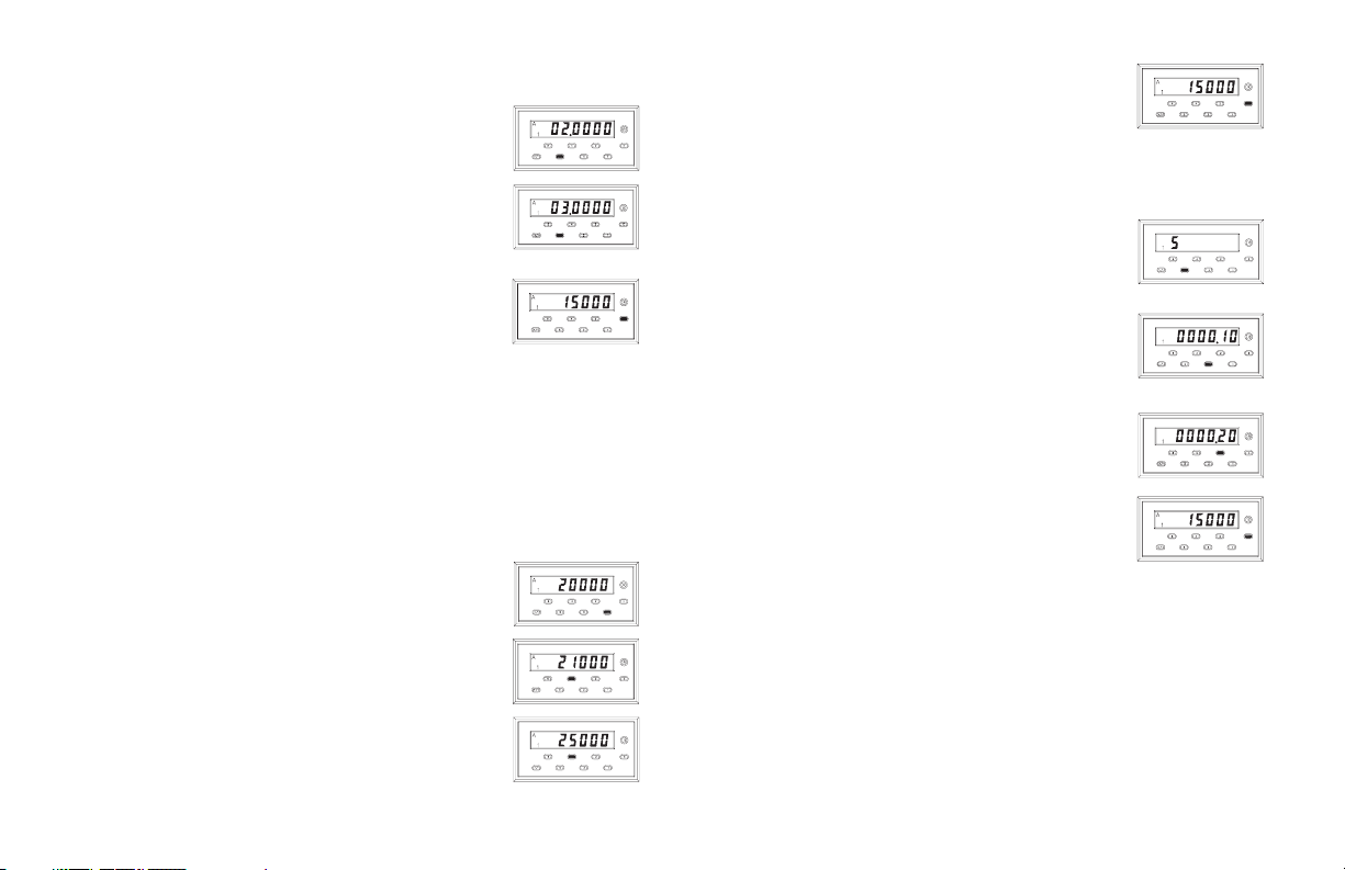
STEP 1 - Enter code 41 (Unit Personality). Select and enter a mode identifier of
1, for the Gemini to operate as a Counter and Rate indicator.
STEP 2 -Enter code42 (ResetButton & Terminal Actuation Modes). Select and
enter mode 2 to reset the counter when reset is activated.
STEP 3 - Enter code43 (Inputs 1 & 2Response Modes). Select and enter mode 1,
“Count with Inhibit”.
STEP 4 - Enter code 44 (Counter B Number of Count Edges). Select and enter
mode 1 for single edge counting.
STEP 5 - Enter code45 (Counter B ScaleMultiplier). Select and enter mode2 for
a scale multiplier of 0.1.
STEP 6 - Enter code 46 (Counter B Decimal Point & Leading Zero Blanking).
Select and enter mode 1 for no decimal point.
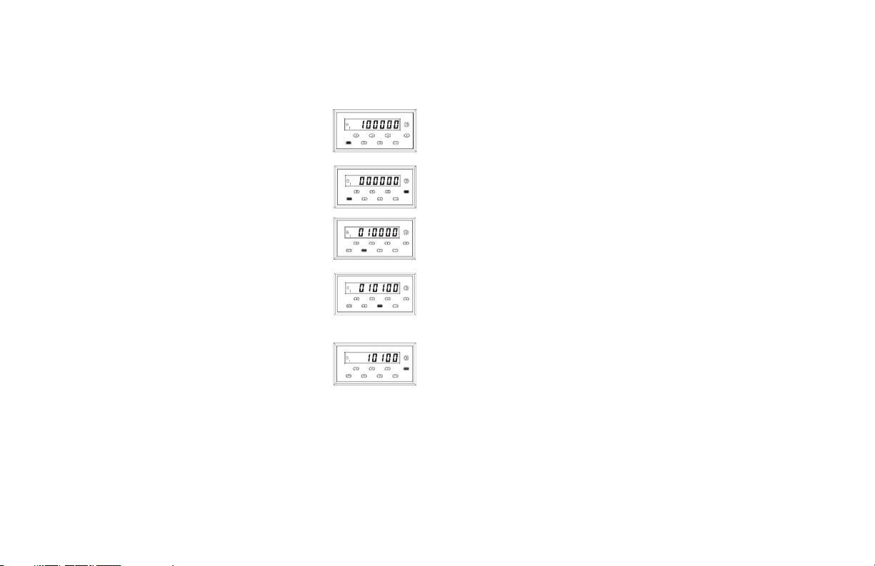
STEP 7 - Enter code 51 (Output Assignment). Select and enter mode 1 to assign
Output 1 to the rate indicator and Output 2 to the counter.
STEP 8 - Enter code 52 (Output 1 Termination Modes). Select andenter mode 6
for boundary operation. Output 1 will activate when the maximum speed
value, Preset 1, is exceeded. Output 1 will deactivate when the rate decreases
to a value below the maximum speed.
Note: The Timed Output 1 Value, code 53, is not used in this application.
STEP 9 - Enter code 54 (Output 2 Termination Modes). Select andenter mode 4
for Output 2 Terminate at Manual Reset.
Note: The Timed Output 2 Value, code 55, is not used in this application.
STEP 10 - Enter code 56 (Counter B Reset Modes). Select and enter mode 1 for
manual reset to zero.
STEP 11 - Enter code 61 (Rate Right Hand Dummy Zeros). Select and enter
mode 4 for no right hand dummy zeros.
STEP 12 - Enter code 62 (Rate Conversion Factor). Select andenter mode 2 for a
Rate Per Minute conversion factor.
STEP 13 - Enter code 63 (Rate Minimum UpdateTime). Select and enter mode1
for a minimum update time of 0.5 Second. If the rate display jumps around, a
larger minimum update time can be used to provide averaging.
STEP 14 - Enter code 64 (Rate Scale Multiplier). Select and enter mode 5 for a
Scale Multiplier of 0.1, as previously determined.
STEP 15- Entercode 65 (Rate Decimal Point & Leading Zero Blanking). Select
and enter mode 1 for no decimal point.
STEP 16 - Enter code 66 (Operator Accessible Functions Modes). Select and
enter mode (+)1 for nofunctions except reset enabled. When the “PGM.DIS.”
terminal is connected to “COMM.”, the only changes that will be possible is
resetting the counter.
STEP 17 -The “+/-” keyis pushed,if necessary,so that the rateis being indicated
on the Gemini 4200. The “3” key is then pushed to call up the Rate Scale
Factor. The value is changed to 0.8333.
STEP 18 - The “+/-” key is pushed, so that the count is being indicated on the
Gemini 4200. The “3” key is then pushed to call up the Counter Scale Factor.
The value is changed to 0.8333.
STEP 19 - Enter aPreset 1value of 250, by pushing the “1” key andchanging the
value to 250.
STEP 20 - Enter a Preset 2 value of 15,000, by pushing the “2” key and changing
the value to 15,000.
After the unit is programmed, the “PGM. DIS.” terminal is connected to
“COMM.” to prevent any unauthorized or accidental mode changes. The
function codes can, however, be called up to view or verify that the proper
modes are entered.
-19-
Page 22

PROGRAMMING INSTRUCTIONS FOR THE DUAL COUNTER VERSION OF THE GEMINI 4000
The first part of this section provides detailed descriptions of the function
command codes for input response modes, reset modes, outputterminations, etc.
Then, using an actual application example, the programming instructions for the
Dual Counter version will be “walked through”, to give the user a full
understanding of the Gemini 4000 programming procedure. The descriptions
below give the function command code first, followed by the individual mode
identifier. The Function Command Code Summary in the appendix, lists all
codes. (Only commands and modes pertaining to the Dual Counter personality
will be discussed in this section.)
CODE 41 - UNIT PERSONALITY
The Gemini can be programmed to operate in one of two different unit
personalities. In each of the two personalities the Gemini operates as a dual
function indicator. The personality selected determines whether display channel
A will indicate rate or count. In both personalities, display channel B operates as
a counter.
When the Unit Personality is changed and entered, all modes and data values
(Presets, Scale Factors, function codes, etc.) will be automatically loaded with
the factory settings for that personality. If, for any reason during programming,it
is desired to return to the factory settings, the “+/” key can be pushed while in
code 41. Then, when the “E” keyis pressed the unit will load the factory settings
into the Gemini.
The programming procedures for the two unit personalities will vary. This
entire section dealswith theunit programmedas a Dual Counterindicator, [41 2].
[41 1] COUNTER(B)/RATE (A) -In this mode,display channel Afunctions as a
rate indicator and display channel B functions as a counter. See
“PROGRAMMING INSTRUCTIONS FOR COUNTER/RATE VERSION
OF THE GEMINI” section for details.
[41 2] DUAL COUNTER - In this mode, both display channels {A & B}
function as counters.
CODE 42 - RESET BUTTON & TERMINAL ACTUATION
MODES
The “Reset Button & Terminal Actuation modes” control the affect that the
reset button and terminal have on the two display channels.
There is a separate “Rst A” terminal which resets Counter A, when activated.
It is provided to allow independent resetting of each channel.
[42 1] RESET COUNTER A
[42 2] RESET COUNTER B
[42 3] RESET COUNTER A & B
CODE 43 - INPUTS1&2RESPONSE MODES
The Gemini has six different input response modes. They are: Count(1) with
Inhibit(2); Count(1) with Up/Down Control (2); Two input anticoincidence
Add(1)/Subtract(2); Separate Inputmode; Quadrature;and Quadrature x4. In all
modes, except [43 4], both counters will respond identically to both inputs.
These modes are most suitable for applications where one channel is used for
control, and the other for totalizing counts.
[43 1] COUNT WITH INHIBIT- Input 1 servesas the count input. Input2 serves
as the Inhibit input. When Input 2 is low, the counters will ignore the count
signal appearing at Input 1. When Input 2 is at a high level, the pulses
appearing at Input 1 will be counted.
[43 2] COUNT WITH UP/DOWN CONTROL - In this mode, count direction
can be controlled by the second input. Input 1 serves as the count input and
Input 2 serves as the direction control signal input. When Input 2 is at a high
level, the counters will count up. When Input 2 is at a low level, the counters
will count down.
[43 3] TWO INPUT ANTICOINCIDENCE ADD/SUBTRACT - This mode
effectively separates count pulses which may simultaneously appear at the
two inputs. The Gemini unit processes the count pulses into a string of
time-separated pulses, sothe internal counters will notlose any counts.Input 1
serves as the add input (count increments) and Input 2 serves as the subtract
input (count decrements).
-20-
Page 23

[43 4] SEPARATE INPUT - In this mode, the two counters, A & B, are
independently controlled by the inputs. Input 1 serves as the Counter A input
and Input 2 serves as the Counter B input.
[43 5] QUADRATURE COUNTING - Quadrature counting modes are primarily
used in positioning and anti-jitter applications. The reason this mode works is
due to the manner in which two pickups are positioned relative to each other.
The signal on Input 2 is a pulse train signal shifted 90° away from the signal on
Input 1. These two signals are processed by the Gemini as follows:
Input 1 serves as the count input, while Input 2 serves as the quadrature input.
For quadrature withsingle edgecounting, thecounters will count in a positive
direction when Input 1 is a negative going edge and Input 2 is at a low level.
The counters willcount ina negative direction whenInput 1 is a positivegoing
edge and Input 2 is at a low level. All transitions on Input 1 are ignored when
Input 2 is at a high level. These logic rules provide the basis for anti-jitter
operation which will prevent false counts from occurring due to back-lash,
vibration, chatter, etc.
When twoedge counting is used, the quadrature mode works the same as with
single edge counting when Input 2 is low. But when Input 2 is at a high level,
counts at Input 1 are no longer ignored. Instead the logic rules for Input 1 are
complemented, allowing both edges of Input 1to becounted. This doubles the
effective resolution of the encoded input.
[43 6] QUADRATURE TIMES 4 - This mode takes the quadrature mode, with
two edge counting, one step further. In quadrature times 4, both Input 1 and
Input 2serve as the count or quadrature input, depending on their state. In one
instance, Input 1 will serve as the count input and Input 2 will serve as the
quadrature input.In another instance, Input 1 will be the quadrature input and
Input 2 will be the count input. This enables each edge, positive and negative
going, of both inputs, 1 and 2, to be counted. This results in a resolution four
times greater than in the basic quadrature x1 mode.
CODE 44 - COUNTERS A & B NUMBER OF COUNT EDGES
The counters of the Gemini can be programmed for either single or two edge
(x2) counting. The number of count edges cannot be set when the count mode is
programmed for quadrature x4 operation. The Gemini will ignore any attempt to
enter function command code 44, when set for quadrature x4.
[44 1] SINGLEEDGE COUNTING (x1) - The unitcounts onthe negativegoing
(falling) edge of the count input signal. The Inputs 1 & 2 Response mode
descriptions describe how each mode uses this method of edge counting.
[44 2] TWO EDGE COUNTING (x2) - This mode is used when doubling of the
count signal input is required. The unit counts on the positive going (rising)
edge of the count input signal, as well as, the negative going (falling) edge.
CODE 45 - COUNTER B SCALE MULTIPLIER
There are four “Counter B Scale Multipliers” that are available. They
effectively divide the internal countB value by 1, 10,100, and 1000 respectively,
to yield the displayed Counter B value. Note: Use of a small scale multiplier in
conjunction with a small Scale Factor could cause the internal count value to be
exceeded before the 6-digit display value is exceeded. See “Programming the
Presets, Scale Factors, Timed Outputs & Counter Load Values” section for
more details.
[45 1] x1
[45 2] x0.1
[45 3] x0.01
[45 4] x0.001
-21-
Page 24

CODE 46 - COUNTER B DECIMAL POINT & LEADING ZERO
BLANKING
There are six basic modes of decimal point placement for Counter B of the
Gemini. The decimal point is placed to the right of the display digit that
corresponds to the mode identifier. (The right most decimal point, digit 1, is
never turned on.) A “-” sign in front of the mode identifier will inhibit leading
zero blanking. The absence of a “-” sign will enable leading zero blanking.
[46 1] 0
[46 2] 0.0
[46 3] 0.0 0 LEADING ZERO
[46 4] 0.0 0 0 BLANKING
[46 5] 0.0000
[46 6] 0.00000
[46 -1] 000000
[46 -2] 00000.0
[46 -3] 0 0 0 0.0 0 LEADING ZERO
[46 -4] 0 0 0.0 0 0 BLANKING INHIBITED
[46 -5] 00.0000
[46 -6] 0.00000
CODE 51 - OUTPUT ASSIGNMENT
The output of the Gemini 4100 is assigned to Counter B, or for the Gemini
4200 one can be assignedto Counter B and theother to Counter A. When bothare
assigned to Counter B, the Gemini will automatically configure the Counter A
Reset Mode to Reset to Zero, [61 1].
The Gemini 4200 has a Preset tracking feature which allows Preset 1 to track
Preset 2. If Preset tracking is programmed, whenever thePreset 2value ischanged,
the Preset 1 value will also change to maintain the same offset. For example, if
Preset 1 is 100 and Preset 2 is 200, changing Preset 2 to 300 will automatically
change Preset 1 to 200, maintaining thesame 100 unit offset. In order to change the
amount of offset, the Preset 1 value is changed. The Preset tracking feature is
programmed by adding a “-” modifier in front of the desired mode.
[51 1] OUTPUT 1 ASSIGNED TO COUNTER A, OUTPUT 2 ASSIGNED TO
COUNTER B (Gemini 4200 Only)
[51 2] OUTPUT 1 & 2 ASSIGNED TO COUNTER (B)
CODE 52 - OUTPUT 1 TERMINATION MODES
The Gemini has six “Output Termination Modes”, which control the way
Output 1 will terminate or reset. In all modes, Output 1 will terminate
immediately when the counter to which it is assigned is manually reset.
Output 1 termination modes 1 & 2 are available only with a Gemini 4200 and
when both outputs are assigned to Counter B, [51 2].
A reverse phase mode is available on the Gemini. This refers to the
complementing of the logic state of the output. With normal phase operation,
when the display value reaches the Preset 1, Output 1 will turn on. The reset
condition of Output 1 is output off. In reverse phase operation, the Output 1 turns
off when the Preset 1 is reached. The reset condition of Output 1 is output on.
(Note: The state of the relay, if used, is also reversed.) A “-” sign in front of the
mode identifier will provide for reverse phase operation. The absence of a “-”
sign will indicate normal phase operation.
[52 1] TERMINATE AT OUTPUT 2 START - Output 1 will terminate when
Output 2 starts.Output 1is set for normal phaseoperation. (Gemini 4200Only)
[52 2] TERMINATE AT OUTPUT 2 END - Output 1 will terminate when
Output 2 ends.Output 1 isset for normal phaseoperation. (Gemini4200 Only)
[52 3] TERMINATE AT MANUAL RESET - Output 1 activates when the
Counter A or Counter B value, whichever it is assigned to, is greater than or
equal to the Preset 1 Value. In this mode, once Output 1 is activated, it does
not deactivate until the moment a reset occurs. Output 1 is set for normal
phase operation.
[52 4] TERMINATE AT MANUAL RESET END - This mode is like the
preceding, except Output 1 deactivates when reset ends. Output 1 is set for
normal phase operation.
-22-
Page 25

[52 5] TERMINATE AFTER TIMED OUTPUT 1 - Once the output has been
activated, it will deactivate after the predetermined length of time (code 53)
has expired. Manual reset will override the timed output and reset Output 1.
Output 1 is set for normal phase operation.
[52 6] BOUNDARY MODE - When in boundary mode, the Preset 1 Value serves
as theboundary point. When the Counter A or B Value (whicheverit isassigned
to) is less than Preset 1, Output 1 is not activated (normal phase). When the
Counter A or B Valueis greaterthan or equal to Preset 1,Output 1 is activated. If
the Counter A or B Value were to drop below Preset 1, Output 1 would then
deactivate. For negative Preset points, Output 1 is not activated when the
Counter A or B Value is morepositive that the Preset 1 Value. Whenthe countis
more negative than or equal to Preset 1, Output 1 is activated. If the count
becomes more positive than Preset 1, Output 1 again deactivates. When the
Preset 1 value is changed, Output 1 will immediately go to the proper state.
Upon power up, Output 1 will “remember” its power down boundary condition
and go to that state. Output 1 is set for normal phase operation. Programming
Boundary mode willautomatically select[61 1] when[51 1] is programmed.
[52 -1]
[52 -2]
[52 -3] These modes are the same as above with the exception
[52 -4] that the output is set for reverse phase operation.
[52 -5]
[52 -6]
CODE 53 - TIMED OUTPUT 1 VALUE
The Gemini has the capabilityof varying the Timed Output 1 Value from 0.01
second to 599.99 seconds. When the code is entered, instead of a single mode
identifier digitbeing displayed, six digits will be shown. Refer to “Programming
the Presets, Scale Factors, Timed Outputs & Counter Load Values” section for
more details about entering. The timed output will be terminated if the unit is
manually reset.
Note: ATimed Output Value of zero cannot be programmed into the Gemini. Ifa
value of 0 is entered into the display and the “E” key is pressed, the unit will
not enter the 0, but will stay in the data entry mode. If a new value is not
entered, it willtime out and the unitwill continueto use its previoussetting.
CODE 54 - OUTPUT 2 TERMINATION MODES
The Gemini 4200 has six “Output 2 Termination Modes”, which control the
way Output 2 will terminate or reset. In all modes, Output 2 will terminate
immediately when Counter B is manually reset.
Output 2 termination modes 1 & 2 are available only when both outputs are
assigned to Counter B, [51 2].
A reverse phase mode is available on the Gemini 4200. This refers to the
complementing of the logic state of the output. With normal phase operation,
when the display value reaches the Preset 2, Output 2 will turn on. The reset
condition of Output 2 is output off. In reverse phase operation, the Output 2 turns
off when the Preset 2 is reached. The reset condition of Output 2 is output on.
(Note: The state of the relay, if used, is also reversed.) A “-” sign in front of the
mode identifier will provide for reverse phase operation. The absence of a “-”
sign will indicate normal phase operation.
[54 1] TERMINATE AT OUTPUT 1 START - Output 2 will terminate when
Output 1 starts. Output 2 is set for normal phase operation.
[54 2] TERMINATE AT OUTPUT 1 END - Output 2 will terminate when
Output 1 ends. Output 2 is set for normal phase operation.
[54 3] TERMINATE AT MANUAL RESET - Output 2 activates when Counter
B is greater than or equal to the Preset 2 Value. In this mode, once Output 2 is
activated, it does not deactivate until themoment a resetoccurs. Output2 is set
for normal phase operation.
[54 4] TERMINATE AT MANUAL RESET END - This mode is like the
preceding, except Output 2 deactivates when reset ends. Output 2 is set for
normal phase operation.
[54 5] TERMINATE AFTER TIMED OUTPUT 2 - Once Output 2 has been
activated, it will deactivate after the predetermined length of time (code 55)
has expired. Manual reset will override the timed output and reset Output 2.
Output 2 is set for normal phase operation.
-23-
Page 26

CODE 54 - OUTPUT 2 TERMINATION MODES (Cont’d)
[54 6] BOUNDARY MODE - Whenin boundarymode the Preset 2 Valueserves
as theboundary point.When the Counter B Value is less than Preset 2,Output
2 isnot activated(normal phase). When theCounter BValue is greater than or
equal to Preset 2, Output 2 is activated. If the Counter B Value were to drop
below Preset 2, Output 2 would then deactivate. For negative Preset points,
Output 2 is not activated when the Counter B Value is more positive that the
Preset 2 Value. When the count is more negative than or equal to Preset 2,
Output 2 is activated. If the countbecomes more positivethan Preset2, Output
2 again deactivates. When the Preset 2 value is changed, Output 2 will
immediately go to the proper state. Upon power up,Output 2will “remember”
its power down boundary condition and go to that state. Output 2 is set for
normal phase operation.
Programming Boundary mode will automatically select [56 1].
[54 -1]
[54 -2]
[54 -3] These modes are the same as above with the exception
[54 -4] that the output is set for reverse phase operation.
[54 -5]
[54 -6]
CODE 55 - TIMED OUTPUT 2 VALUE (GEMINI 4200 ONLY)
The Gemini 4200 has thecapability of varying the TimedOutput 2 Value from
0.01 second to 599.99 seconds. When the code is entered, instead of a single
mode identifier digit being displayed, six digits will be shown. Refer to
“Programming the Presets, Scale Factors, Timed Outputs & Counter Load
Values” section for more details about entering. The timed output will be
terminated if the unit is manually reset.
Note: ATimed Output Value of zero cannot beprogrammed into the Gemini 4200.
If avalue of0 is entered into the display and the “E” key ispressed, theunit will
not enterthe 0, but will stay in the data entry mode. If a new value is not entered,
it will time out and the unit will continue to use its previous setting.
CODE 56 - COUNTER B RESET MODES
The Gemini has six different Counter B reset modes. Note: For Gemini 4200
all reset to preset modes reset to preset 2. There are also two methods by which
manual reset can act on the counter (reset must be enabled, see function code 66
and dip switch set-up). The first is a “maintained” reset action, where the unit is
held at reset for as long as the reset terminal or reset button is activated. The
second is a “momentary” reset, in which the unit resets, when reset is activated,
and starts counting even though the reset terminal or reset button may still be
active. A “-” sign in front of the mode identifier indicates “momentary” reset
action, the absence of the “-” sign indicates “maintained” reset action.
In “Resetto Zero”modes the Output activatesat thePreset Value.In “Resetto
Preset” modes, the Output activates at zero.
In the “Reset to Preset” modes, for proper operation, the counter normally
counts down. In the “Count with Inhibit” and “Separate Inputs” input response
modes, [43 1, or 4], the unit will automatically count down if a Reset to Preset
mode is selected. In the other input response modes, proper input phasing is
required for down counting. See “CODE 43 - INPUTS 1 & 2 RESPONSE
MODES” section for details.
The activation and de-activation response time for reset is 10 msec.
[56 1] MANUAL RESET TO ZERO (RTZ) - Manual reset to zero is
accomplished by pulling the “RST.” terminal to “COMMON” or, if the front
panel reset is enabled, by pressing the front panel reset button. Reset is
“maintained”.
[56 2] MANUAL RESET TO PRESET (RTP) - Manual reset to Preset is
accomplished by pulling the “RST.” terminal to “COMMON” or, if the front
panel reset is enabled, by pressing the front panel reset button. Reset is
“maintained”.
[56 3] AUTOMATIC RESET TO ZERO AFTER TIMED OUTPUT - The
counter automatically resets to zero whenTimed Output ends. Manual reset is
“maintained” and will override automatic reset.
[56 4] AUTOMATIC RESET TO PRESET AFTER TIMED OUTPUT - The
counter automatically resets to Preset when Timed Output ends. Manual reset
is “maintained” and will override automatic reset.
-24-
Page 27

[56 5] AUTOMATIC RESET TO ZERO AT BEGINNING OF TIMED
OUTPUT (AT PRESET) - In this reset mode, the counter will automatically
reset to zero at the beginning of Timed Output (at Preset). The Timed Output
Value must be shorter than the time required for the counter to count to the
Preset 2 Value, otherwise, the Output will appear to be latched on. Manual
reset is “maintained” and will override automatic reset.
[56 6] AUTOMATIC RESET TO PRESET AT BEGINNING OF TIMED
OUTPUT (AT ZERO)- Inthis reset mode, thecounter will automatically reset
to Presetat the beginning of Timed Output (at zero). The Timed Output Value
must be shorter than the time required for the counter to count to zero,
otherwise, the Output will appear to be latched on. Manual reset is
“maintained” and will override automatic reset.
[56 -1]
[56 -2]
[56 -3] These modes are the same as above with the exception
[56 -4] that manual reset is set for “momentary” operation.
[56 -5]
[56 -6]
CODE 61 - COUNTER (A) RESET MODES
There are two ways to reset Counter A. The reset button or “RST.” terminal
can be used, if the appropriate “Reset Button & Terminal Activation Mode” is
programmed. The second way is the use of the “RST.A” terminal. If it is
necessary to reset Counter A & B independently, the “Reset Button & Terminal
Activation Mode” should be programmed to Reset Counter B, and the “RST.A”
terminal should then be used to reset Counter A.
For the Gemini 4200, if both outputs are assigned to Counter B [51 2], or the
Output 1 Termination mode is boundary [54 6], the only Counter A Reset mode
that is available is Reset to Zero [61 1].
There are twomethods by whichmanual reset canact onCounter A(reset must
be enabled - see function code 66 and dip switch set-up). The first is a
“maintained” reset action, where the unit is held at reset for as long as the reset
terminal or reset button is activated. Thesecond isa “momentary” reset, in which
the unit resets, when reset is activated, and starts counting even though the
terminal or reset button may still be active. A “-” sign in front of the mode
identifier indicates “momentary” reset action, the absence of the “-” sign
indicates “maintained” reset action.
The activation and de-activation response time for reset is 10 msec.
[61 1] MANUAL RESET TO ZERO (RTZ) - Manual reset to zero is
accomplished by activating the appropriate reset button or terminal. Reset is
“maintained”.
The following modes are only available on the Gemini 4200
[61 2] MANUAL RESET TO PRESET 1 (RTP) - Manual reset to Preset 1 is
accomplished by pulling the “RST.” terminal to “COMMON” or, if the front
panel reset is enabled, by pressing the front panel reset button. Reset is
“maintained”.
[61 3] AUTOMATIC RESET TO ZERO AFTER TIMED OUTPUT 1 - The
counter automatically resets to zero when Timed Output 1 ends. Manual reset
is “maintained” and will override automatic reset.
[61 4] AUTOMATIC RESET TO PRESET 1 AFTER TIMED OUTPUT 1 - The
counter automatically resets to Preset 1 when Timed Output 1 ends. Manual
reset is “maintained” and will override automatic reset.
[61 5] AUTOMATIC RESET TO ZERO AT BEGINNING OF TIMED
OUTPUT 1 (AT PRESET 1) - In this reset mode, the counter will
automatically reset to zero at the beginning of Timed Output 1 (at Preset 1).
The Timed Output1 Value (code 53)must be shorter than thetime required for
the counter tocount to the Preset 1Value, otherwise,Output 1 will appear tobe
latched on. Manual reset is “maintained” and will override automatic reset.
[61 6] AUTOMATIC RESET TO PRESET 1 AT BEGINNING OF TIMED
OUTPUT 1 (AT ZERO) - In this reset mode, the counter will automatically
reset to Preset 1 at the beginning of Timed Output 1 (at zero). The Timed 1
Output Value (code 53) must be shorter than the time required for the counter
to count to zero, otherwise,Output 1 will appear tobe latchedon. Manual reset
is “maintained” and will override automatic reset.
[61 -1]
[61 -2]
[61 -3] These modes are the same as above with the exception
[61 -4] that manual reset is set for “momentary” operation.
[61 -5]
[61 -6]
-25-
Page 28

CODE 64 - COUNTER A SCALE MULTIPLIER
There arefour Counter A scale multipliers that are available. They effectively
divide the internal Counter A Value by1, 10, 100, and 1000 respectively, toyield
the displayed Counter A Value. Note: Use of a small scale multiplier in
conjunction with a small Scale Factor could cause the internal Counter A Value
to be exceeded before the 6-digit display value is exceeded.
[64 1] x1
[64 2] x0.1
[64 3] x0.01
[64 4] x0.001
CODE 65 - COUNTER A DECIMAL POINT & LEADING ZERO
BLANKING
There are six basic modes of decimal point placement for Counter A of the
Gemini. The decimal point is placed to the right of the display digit that
corresponds to the mode identifier. (The right most decimal point, digit 1, is
never turned on.) A “-” sign in front of the mode identifier will inhibit leading
zero blanking. The absence of a “-” sign will enable leading zero blanking.
[65 1] 0
[65 2] 0.0
[65 3] 0.0 0 LEADING ZERO
[65 4] 0.0 0 0 BLANKING
[65 5] 0.0000
[65 6] 0.00000
[65-1] 000000
[65-2] 00000.0
[65-3] 0 0 0 0.0 0 LEADING ZERO
[65-4] 0 0 0.0 0 0 BLANKING INHIBITED
[65-5] 00.0000
[65-6] 0.00000
CODE 66 - “OPERATOR ACCESSIBLE FUNCTIONS” MODES
The Gemini has six basic levels of “Operator Accessible Functions”. Each of
these levels can be modified to enable or disable manual reset. When the “PGM.
DIS.” (program disable) terminal is connected to “COMMON”, access to all
functions is disabled except forthose listed below which willremain enabled.All
of the function codes and parameters can be interrogated, regardless of the
“Operator Accessible Functions” mode selected.
A “-” sign in front of the mode identifier will disable the front panel Reset
button and the “RST.” terminal.
Note: The front panel reset button can be independently disabled by using the
disable reset DIP switch.
[66 1] NO FUNCTIONS ENABLED EXCEPT RESET - In this mode, manual
reset is enabled, but none of the programming functions can be changed.
[66 2] PRESET PROGRAMMING AND RESET ENABLED - In this mode,
manual reset and the programming of the Preset Values are enabled.
[66 3] SCALE FACTOR PROGRAMMING AND RESET ENABLED - In this
mode, manual resetand the programming of the Scale FactorValues are enabled.
[66 4] SCALE FACTOR, PRESET PROGRAMMING AND RESET
ENABLED In this mode, manual reset and the programming of the Scale
Factor and Preset Values are enabled.
[66 5] PRESET, COUNTER LOAD PROGRAMMING, AND RESET
ENABLED - In this mode, manual reset and the programming of the Presets
and Counter Load Values are enabled.
[66 6] PRESET, SCALE FACTOR, COUNTER LOAD PROGRAMMING,
AND RESET ENABLED- In this mode, manualreset and theprogramming of
the Preset, Scale Factor and Counter Load Values are enabled.
[66 -1]
[66 -2]
[66 -3] These modes are the same as above with
[66 -4] the exception that reset is disabled.
[66 -5]
[66 -6]
-26-
Page 29

PRESET VALUES
Whenever the display value equals the preset value, an output action will occur. This
action depends on the previously programmed modes. The preset values may vary from
-999,999 to 999,999. (Refer to “Programming the Presets, Scale Factors,Timed Outputs
& Counter Load Values” for instructions on entering the preset values.)
The Scale Factorwill have a direct effecton the preset value beingentered. For a Scale
Factor Value greater than one, the preset value should be an integer multiple of the Scale
Factor. If it is not, the Gemini will automatically adjust the preset value up or down to
force it to be evenly divisible by the Scale Factor.
“1” - PRESET 1 VALUE
“2” - PRESET 2 VALUE (GEMINI 4200 Only)
SCALE FACTORS A & B
“3” SCALE FACTOR - The Scale Factor, for the Value (Counter A or Counter B)
that is currently being displayed, is accessedby pressingthe “3” key. To access the Scale
Factor of the “other” displayvalue, the“+/-” key would be pushed (to changethe display
to the other value), then the “3” key would be pushed.
The number of pulses counted (internal countvalue) ismultiplied by the Scale Factor,
which changes the displayed value accordingly. A Scale Factor Value of 1.0000 would
result in a display of the actual number of input pulses that have been counted. The Scale
Factor is used primarily for conversion from existing pulses per unit of measure to the
required displayed units. This includes conversion from different units of measure (i.e
feet to meters, etc.). The Scale Factor Values may range from -5.9999 to +5.9999. Refer
to “Programming the Presets, Scale Factors, Timed Output & Counter LoadValues” for
entering instructions.
It is important to note that theprecision of a counter application cannot be improved by
using a Scale Factor greater than one. To accomplish greater precision, more pulse
information must be generated per measuring unit. For example, if 5 pulses are being
received per foot of material, the precision of 10th of feet cannot be attained by simply
programming a Scale Factor of 2.0000, even though the display is reading in 10ths. In this
case, the display will increment by two for each count input. Thus if an odd preset value
was entered, such as 6.7ft., the Geminiwill alter the preset toread in even tenths offeet.
COUNTER LOAD VALUES
The Counter Load Value is provided to allow the user to modify the
Counter A or B values. The Counter Load Values are reset to zero when
the Gemini is powered up. Once the Counter Load Value has been
changed, it will remain set to that value untilthe unit is powered downand
up. Accessing the Counter Load Value for the counter that is currently
being displayed is done by pushing the “E” button and while being held
down also pushing the “+/-” button.
“E” & “+/-”- Counter LoadValue for thecurrently displayed counter.
Note: Useof asmall ScaleFactor inconjunction with a small scale multiplier could cause
the internal count value to be exceeded before the 6-digit display value is exceeded.
-27-
Page 30

DUAL COUNTER BATCHING APPLICATION
A typical application for the Gemini 4200 will requirea slowdown outputand
a final cut output for cut. In this application the user also desires a total count of
pieces cut per shift, or per order. The Gemini 4200 can easily be programmed to
handle these requirements.
A manufacturer of cardboard packaging inserts needs to cut various length
cardboard inserts to a 32ndth of an inch tolerance. To achieve this accuracy, an
RPGB 1200 coupled to a length sensor conversion bracket and a 1 foot
circumference wheel will be used. The sensor will provide 1200 pulses per foot or
100 pulses per inch. Thiswill enable the cutbe madeto 100thof an inch accuracy.
The lengthof the cardboard insert will vary from run to run, howeverthe slow
down output needs to occur 5 inches before the final cut is to be made. This
requirement can be handled easily with the Gemini 4200’s preset tracking
feature. The Preset 1 value is initially programmed to be 5 inches less than the
Preset 2 value.(Preset 2 must be programmed first.) Then whenever the length of
the cardboard insert is changed (Preset 2), the Gemini will automatically adjust
Preset 1 to be 5 inches less than the new Preset 2 value.
The last requirementis to totalize the number ofpieces cut. This is achievedby
using the output cut pulse at “O2 SNK”, as an input count pulse to Input 1 of the
Gemini 4200. TheInputs 1 & 2 Response modeof the unit would beprogrammed
to the “Separate Inputs” mode. Then, whenever a cut is made, the Gemini would
increment Counter A to provide a total count of pieces cut.
HARDWARE SET-UP
The application drawing shows how the hardware for this system is to be
connected.
The normally open contact of relay 1 is connected to the slow down actuator.
The normally open contact of relay 2 is connected to the knife actuator. The “O2
SNK” output is connectedto Input1, whichwill providea input pulse to Counter
A each time a piece is cut.
The Dip switches are setup as shown. Input 1 is set-up to work with an open
collector output. The number ofpieces cut will be far less than100/ sec. therefore
the “HI/LO FRQ” switch for Input 1 is placed in the “LO FRQ” position for
higher noise immunity. Input 2 is also set-up to work with an open collector
output. The “HI/LO FRQ” switch is placed in the “HI FRQ” position since the
count frequenciesinvolved will be over 100 cps. The “EN/DIS RST” switch (8),
is set to “EN RST” to allow front panel reset.
SCALING FOR COUNTER A
Counter A is used to totalize the number of pieces cut. There is 1 pulse
provided for each piece cut. Counter A, therefore, does not require special
scaling. The Gemini4200 is simply leftat itsfactory settings of 1for ScaleFactor
A and Scale Multiplier A.
-28-
Page 31

SCALING FOR COUNTER B
Counter B is used to control the length of the cardboard insert. The display
reading for Counter B is to be in hundredths of an inch. The “Number of Pulses”
per 1200 “Display Units” (1200 hundredths of an inch = 1 foot) is 1200. It can
easily be seen that 1 pulse will provide for 1 “Display Unit” of indication (1
hundredth of an inch). The Gemini 4200can therefore be left at its ScaleFactor B
and Scale Multiplier B factory settings of 1. The “Counter A & B Number of
Count Edges”, code 44, is also left at the factor set value of 1.
STEP BY STEP PROGRAMMING OF THE GEMINI 4200
STEP 1 -Enter code 41 (Unit Personality). Selectand enter mode 2 to set theUnit
Personality to Dual Counter.
STEP 2 - Enter code 42 (“Reset Button & Terminal Actuation Mode”). Select
and enter mode 2 so reset will reset Counter B. This will allow Counter B to be
reset when the front panel reset button is pushed.
STEP 3 - Enter code43 (“Inputs1 & 2 Response Modes”). Selectand enter mode4
for Separate Inputsmode (Input 1= Counter Ainput, Input 2 = CounterB input).
STEP 4- Entercode 44 (“Counters A & B Number of Count Edges”). Select and
enter mode 1 for single edge counting.
STEP 5 - Enter code45 (Counter B ScaleMultiplier). Select and enter mode1 for
a scale multiplier of 1.
STEP 6 - Enter code 46 (Counter B Decimal Point & Lead Zero Blanking).
Select and enter mode 3 for a decimal point in the hundredths location.
STEP 7 - Enter code 51 (Output Assignment). Select and enter mode (-)2 to
assign both outputs to Counter B and enable preset tracking.
STEP 8 - Enter code 52 (Output 1 Termination Modes). Select andenter mode 2
for termination at Output 2 end.
Note: The Timed Output 1 Value, code 53 is not used in this application.
STEP 9 - Enter code 54 (Output 2 Termination Modes). Select and enter mode 5
for timed output operation.
STEP 10 - Enter code 55 (Timed Output 2 Value). Change the value to 0.50 and
enter.
STEP 11 - Enter code 56 (Counter B Reset Modes). Select and enter mode 5 for
AutomaticResettoZeroatPreset2.
Note: Code 61 (Counter A Reset Modes) was automatically selected to mode
1, Reset to Zero, when mode [51 2] was programmed.
STEP 12 - Enter code 64 (Counter A Scale Multiplier). Select and enter mode 1
for a scale multiplier of 1.
STEP 13 - Enter code 65 (Counter A Decimal Point & Leading Zero Blanking).
Select and enter mode 1 for no decimal point.
STEP 14 - Enter code 66 (Operator Accessible Functions Modes). Select and
enter mode 2 for Preset programming and reset enabled. When the
“PGM.DIS.” terminal isconnected to“COMM.”, the only changes thatwill be
possible are resetting the unit and changing the Preset.
The Gemini 4200in now fully programmed. Jumperthe “PGM.DIS.” terminal
to “COMM.”to prevent accidental programchanges and to enable the “Operator
Accessible Functions”.
-29-
Page 32

20 MA CURRENT LOOP COMMUNICATIONS
The Gemini 4000’s 20 mA Current Loop Communications Option allows a
“two-way” serial communications link to be established in order to monitor the
count, rate, Presets and Scale Factors from a remote location. Some typical
devices that can be connected with the Gemini are: a printer, terminal,
programmable controller, or host computer. Fordevices that use RS232, a GCM
Serial Converter Module is available to convert the 20 mA Current Loop signals
to RS232 and vice-versa.
There are two loops that must be established. One for sending commands to
the Gemini and one for receiving the data values from the Gemini. Up to sixteen
Geminis can be connected together in the “loop”. These units are assigned unit
addresses by setting the Serial DIP Switches on each unit. The applications can
be as simple as attaching a printer to obtain hard copy of the count information or
as involved as using a host computerto automatically set up the Presetsand Scale
Factors of a number of Gemini units.
With the Serial Loop Option, the following functions can be performed:
1. Interrogation of the Count, Rate, Presets, and Scale Factors.
2. Changing of the Presets and Scale Factors.
3. Resetting of the Count values.
4. Automatic print-out when using a printer and the Print Request Terminal.
5. Change viewed display channel.
COMMUNICATION FORMAT
Data is sentby switching off and on thecurrent in the20 mA currentloop. Data
is receivedby monitoring the switching action and interpretingthe codesthat are
transmitted. In order for data to be interpreted correctly, there must be identical
formats and Baud Rates. The format that the Gemini will accept is: 1 start bit, 7
data bits, 1 odd parity bit, and 1 stop bit. The Baud Rates that are available are:
300, 600, 1200 and 2400.
The selection of the Baud Rate is accomplished bysetting DIPswitches. Refer
to the Current Loop Installation section, for set-up instructions.
FIG. 1: DATA FORMAT-10 BIT FRAME [300, 600, 1200, 2400 Baud]
SENDING COMMANDS & DATA TO THE GEMINI
When sending commands to the Gemini, a command string must be
constructed. The command string may consist of command codes, value
identifiers, and numerical data. Below is a list of commands and value identifiers
that are used when communicating with the Gemini.
COMMAND DESCRIPTION
N (4EH) Address command; followed by a unit address number 1-15
P (50H) Transmit per Print Options command.
R (52H) Reset command; operates on Count values and output
T (54H) Transmit Value command; operates on Rate or Count values,
V (56H) Change Value command; operates on Scale Factors, and the
D (44H) Change Display command; operateson Display values E &F.
and one of the following commands.
Preset and Scale Factors.
Preset.
VALUE
IDENTIFIER
A (41H) Preset 1 (PS1)
B (42H) Preset 2 (PS2)
C (43H) Scale Factor A (SFA)
D (44H) Scale Factor B (SFB)
E (45H) Rate or Count A (CTA)
F (46H) Count B (CTB)
DESCRIPTION MNEMONIC
-30-
Page 33

The command string is constructed by using the above commands and value
identifiers along with the data values that are required. Data values may or may
not contain the decimal point if a decimal point is programmed into the Gemini.
The Gemini will accept the decimal points, however, it does not interpret them in
any way. Leading zeros can be eliminated, however, all trailing zeros must be
present. For example, if a Scale Factor of 1.0000 is to be sent, the data value can
be transmitted as 1.0000 or 10000. If a “1” is transmitted,the ScaleFactor will be
changed to 0.0001.
The Addresscommand is used toallow a command to be directed to a specific
unit in the Serial Communications Loop. Whenever the unit address is zero,
transmission of the Address command is not required. This is done for
applications which do not require more than one Gemini. For applications that
require several units, it is recommended that each Gemini in the loop be given a
separate address. If they are given the same address, a command such as the
Transmit Value Command, will cause all the units to respond at the same time,
resulting in erroneous data.
The command string is constructedin aspecific logicalsequence. The Gemini
will not accept command strings that do not follow this sequence. Only one
operation can be performed per command string. Below is the procedure to be
used when constructing a command string.
1. If the Gemini, to whichthe command is to be sent,is assigned an address other
than zero, the first two characters of the command string must consist of the
Address Command (N) and the address number of the unit (1-15).
2. The next characters in the command string is the actual command that the
Gemini isto perform and the value identifier if it pertains to the command. (A
command such as the Transmit per Print Options, “P”, command does not
require a Value Identifier.)
3. If the “Change Value” command is being used, the next characters in the
command string is the numerical data value.
4. The last character in the command string is the command terminator (*). This
character must be sent in order to tell the Gemini that the command string is
complete, so that they can begin processing the command.
Below are some typical examples of properly constructed command strings.
(EX. 1) Change Preset 1 on the Gemini with address of 2 to 00123.4.
COMMAND STRING: N2VA1234*
(EX. 2) Have the Gemini with address of 3 transmit the Count B value.
COMMAND STRING: N3TF*
(EX. 3) Reset Counter B of the Gemini with address of 0.
COMMAND STRING: RF*
As shown, all commands must be terminated with a “Command Terminator”
(* or 2AH). The Gemini will not process the command until the terminator is
sent. If illegal commands or characters are sent to the Gemini, they still would
need to be terminated by an (*).If theyare notterminated, the next command will
not be accepted.
When writing application programs in Basic, the transmission of spaces or
carriage return and line feedshould beinhibited by using the semicolon delimiter
with the“PRINT” statement. The Gemini will not accept a carriage return orline
feed as valid characters.
When a “Change Value” command is sent to the Gemini, a short amount of
time is requiredfor theunit to process the data. This time increases with the count
rate. During this time, only one additional command may be sent to the Gemini.
Thismaybedone80msecafterthetransmissionofthe“ChangeValue”
command. After the second command has been transmitted, the unit will ignore
any further commands until 10 msec after both the “Change Value” and second
command have been processed. It is recommended that a “Transmit Value”
command follow a “Change Value” Command. If this is done, the reception of
the data can provide a timing reference for sending another command and will
insure that the change has occurred.
-31-
Page 34

SENDING COMMANDS & DATA TO THE GEMINI (Cont’d)
The timing diagrams show the timing considerations that need to be made.
FIG. 2: TIMING FOR SENDING COMMANDS
A typical transmission, with the “PR. ID” (Print ID) switch in the up position,
is shown below.
(**) This is the time that it takes the Gemini 4000 to process the preset.
It varies with the Count Rate and Scale Factor Value.
FIG. 3: RESET COMMAND TIMING
RECEIVING DATA FROM THE GEMINI
Data is transmitted from the Gemini when a “Transmit Value” or “Transmit
per Print Options” command is sent to the unit, or when the “PRINT REQ.”
terminal is activated. The Gemini can transmit 6 values: display channel A,
display channel B, Preset 1, Preset 2, Scale FactorA, andScale Factor B. A list of
the abbreviations usedwhen the Gemini transmits the values areshown below.
CTA - Counter A or Rate A Value
CTB - Counter B Value
PS1 - Preset 1
PS2 - Preset 2
SFA - Scale Factor A
SFB - Scale Factor B
The first two digits transmitted are the unit address followed by two blank
spaces. If the unit address is 0, the first locations will be left blank. Thenext three
letters arethe abbreviation for the mnemonic valuefollowed by one blank space.
The actual values are transmitted last. Negative values are indicated by a “-”
sign. For positive values, the “+” sign is not transmitted. Overflowed count
values are shown by an asterisk preceding the most significant digit of the value.
The decimal point position will “float” within the data field depending on the
actual value it represents.
For peripheral control purposes, a single line transmission will have a <CR>
attached to the end ofthe above string. For a“T” commandor each line of ablock
transmission, only the above character string is sent. For the last line of a block
transmission, a <SP> <CR> <LF> is attached to the end of the above character
string. An example of a typical serial transmission:
3 CTB -1234.56 < CR> < LF>
If the “Print Request” terminal initiates the transmission, a 400 msec delay is
inserted before the transmission to keep multiple transmissions from
overrunning the printer.
When thePrint ID switch is in the down position, theunit will not transmit the
characters before the data value (address, Value ID, spaces) or the 400 msec
printer delay. The same above value when transmitted with the “PR.ID” switch
in the down position, is transmitted as:
-1234.56 < CR> < LF>
Note: When using the Gemini with a printer, with the “Print ID” switch in the
down position, some printers may not work, since the printer delay is not
transmitted.
-32-
Page 35

PRINT OPTIONS
The various Print Options are used mainly in conjunction with a printer and
the Print Request Terminal. They provide a choice of Gemini data values to be
printed when eitherthe Print Request Terminalis activated or the “Transmit per
Print Options” (P) command is sent to the Gemini. The various Print Options
available are:
A. Print Display A count or rate value
B. Print Display B Count Value
C. Print Display A & B Values
D. Print Preset 1 & 2 and Scale Factors A & B
E. Print Display B, Presets 1 & 2, and Scale Factors A & B
F. Print Display A, Presets 1 & 2, and Scale Factors A & B
G. Print Display A & B, Presets 1 & 2, and Scale Factors A & B
A typical print-out is shown below. ThePrint Optionsare selectedby setting S3,
S4 and S5 on the Serial DIP Switch. See Page 34 for the various switch settings.
1 CTA 000054
1 PS1 000100
1 PS2 000500
1 SFA 01.0000
1 SFB 02.5000
-33-
Page 36

CURRENT LOOP INSTALLATION
WIRING CONNECTIONS
When wiring the 20 mA current loop, remove the 7-position terminal block
(TBD), located on the right side ofthe topboard. Refer to the numbers listed with
the terminal descriptions below or on the top label, and install each wire in its
proper location on the terminal block. When all connections are made, replace
the terminal block into its proper location.
It is recommended that shielded (screened) cable be used for serial
communications. This unit meets the EMC specifications using ALPHA #2404
cable or equivalent. There are higher grades of shielded cable, such as, four
conductor twisted pair, that offer an even higher degree of noise immunity.
TERMINAL DESCRIPTIONS FOR TERMINAL BLOCK TBD
1. -20 mA SRC (COMM.) - Common
2. PRINT REQUEST - The Print Request Terminal is pulled low to request the
Gemini to transmitaccording tothe Print Options modethat has been selected.
(Minimum Activation time = 25 msec.)
3. +20 mA SRC - The 20mA SRC terminal provides thesource current for one of
the loops.
4. SO- (Serial Out-) -
5. SO+ (Serial Out+) -
The Gemini transmits the requested data on these terminals. They are
connected in series to the receive input of the device to be connected.
6. SI- (Serial In-) -
7. SI+ (Serial In+) -
The Gemini receives commands on these terminals. They are connected in
series with the transmit or output terminals of the device to be connected.
Note: The serial Input terminals must be held in the mark condition (current on)
in order for the Gemini to respond to a Print Request terminal activation.
SERIAL DIP SWITCH SET-UP
The Serial DIP switches areaccessible through the side ofthe Gemini. A list of
the DIP switch positions and their functions are shown in the figure at right.
BR0 & BR1, BAUD RATE- Set-up is shown ,at right. Whenchanging theBaud
Rate, the unit should be powered-down and then powered back up again. The
unit will onlyrecognize a baud rate changeupon power-up,after activating the
“Print Request” terminal or after a few characters have been sent at the new
baud rate (If the two previous conditions have not occurred, the Gemini will
see the charactersas erroneousand it will check the baud rate and set itself to
operate at the new rate).
PR.ID - PRINT ID. -When this switch isin the up position,the Gemini willprint
the unit address, data value ID and the data value when a transmission is
requested. The unit will also insert a 400 msec delay between transmissions
when the “P” command or Print Request terminal is used. This switch
position is generally used when the unit is connected with a printer.
When the switch is in the down position, the Gemini will transmit only the data
value, withoutthe unit addressand data ID.The 400 msec delay, described above,
will not be inserted. This switch position usage is intended for applications where
the Gemini is communicating with a computer. In these circumstances printing
the address and value ID and inserting a 400 msec print delay is usually
unnecessary and needlessly slows down communication throughput.
PC0, PC1, & PC2, PRINT OPTIONS - Used to control which values are
printed out when the Print Request terminal is activated or when the Transmit
per Print Options command “P” is sent to the Gemini 4000.
AD0, AD1, AD2, & AD3 UNIT ADDRESS - These switches are used to give
each unit aseparate address when more than one unit isconnected in the Loop.
See below for Switch Set-up.
-34-
Page 37

COMMUNICATIONS APPLICATION
PROCESS MONITORING SYSTEM
Five Geminis with 20 mA Current Loop Option, are used to
monitor and control parts packaging machines in a plant. The
units are located at each of the machines in the production area
of the building. The communications lines are run to an
Industrial computer located in the production offices.
[OTHER GEMINIS OR RLC PRODUCTS WITH 20 MA CURRENT LOOP
CAN BE CONNECTED IN THE SAME LOOP.]
The drawing below shows the Current Loop set-up. Each
Gemini is given anaddress andthe Serial DIP switches are set
accordingly. A BaudRate of 1200 is selected andset in eachof
the Geminis. An application program is written, which sends
and retrieves data from the units using the Change and
Transmit Value commands.
NOTE: The Gemini DC out (terminals 4 & 5)
could be used in place of the external 12
VDC supply.
-35-
Page 38

TROUBLESHOOTING GEMINI SERIAL COMMUNICATIONS
If problems are encountered when trying to get the Gemini(s) and host
device orprinter to communicate,the followingchecklist canbe usedto helpfind
the solution.
1. Check all wiring. Refer to the previous application examples and use themas a
guide to check your serial communication wiring. Proper polarity of all
Geminis and other peripherals mustbe observed. If a multimeter orammeter is
available, insertit in series in eachSerial loop and check forcurrent flow with
all units powered up. If no current is flowing, either the loop is not wired
correctly, or some other fault has occurred. If too much current has been sent
through a Serial Input or Output, the unit mayhave beendamaged. If a Gemini
is suspected, it can be tested for operation by using the Serial Loop-back test
described in the next section.
2. If the Gemini is set-up with a “host computer”, device or printer, check to
make sure that the computer or device is configured with the same
communication format as the Gemini. The only communication format the
Gemini will accept is; 1 start bit, 7 data bits, odd parity, and 1 stop bit.
3. Checkthe baud rate settings and make sure all devices in theloop are set to the
same baud rate.
4. Check the Gemini’s unit address. If the Address command is not used when
transmitting a command to the Gemini, the Gemini’s address must be set to 0.
See “Sending Commands & Data to the Gemini” section for command
structure.
5. If two-way communications are to be established between the Gemini and a
computer, try getting the computer to receive transmissions from the Gemini
first. The Gemini’s “PRINT REQ.” terminal can be used to initiate the
transmissions from the Gemini.
6. When sending commands to the Gemini, the * (2Ah) must terminate the
command. NO CARRIAGE RETURNS (0Dh) OR LINE FEED (0Ah)
CHARACTERS SHOULD BE SENT TO THE GEMINI. If they are sent, the
Gemini will not respond to the next command.
7. Forapplications where1200 Baud or lower is used, thecommand terminator (*)
can be sent before the string to eliminate any illegally transmitted characters.
SERIAL LOOP-BACK SELF-TEST
The Gemini has a Serial Loop-back Self-test feature. Thistest enablesthe user
to verify the operation of the Gemini when problems are encountered trying to
get the Gemini and “Host device” communicating. In this test, the Gemini’s
Serial Input and Output Loops are connected together with the 20 mA source
supplying the loop current. The Gemini then transmits data“to itself”.If the data
is received properly, the Gemini will change its Scale Factor B value to 0.1111.
To perform the loop-back test, follow the test sequence as described below.
1. With the unit powered down, wire up the serial terminal block, “TBD”,as
shown in the diagram below.
2. Setthe Gemini’sunit address to 15 (set switches7-10 of the Serial DIP Switch
to the down position).
3. Apply power to the unit. On power-up the Gemini will perform the loop-back
test. To check the results: Call upthe ScaleFactor Bvalue bypressing the“3”
key while the Counter B value is being displayed. If the Serial loop is
functioning properly the Scale Factor B value will be 0.1111. If this result is
not obtained, double check the connections with those shown in the diagram,
and the unit address switch positions and repeat step 3.
4. If the connection between the Print Request terminal, “PRINT REQ.” and
“COMMON” is disconnected while the unit is under power, the Scale Factor
B value will change back to its previous setting.
If the unit does notpass thistest, contact your localRed Lion Controls distributor.
-36-
Page 39

APPENDIX “A” - INSTALLATION & INPUT CONFIGURATION SWITCH SET-UP
Installation Environment
Before installing the Gemini into the panel, the user should first become
familiar with theunit. It mayalso be desirable to programthe unitand appropriate
DIP switches for the application at hand (Refer to the “Programming and
Applications” sections). Once the unitis programmed,the settings will be saved
in memory. The Program Disable “PGM. DIS.” terminal should be connected to
“COMM.” to prevent accidental or unauthorized programming changes.
The unit should be installed in a location that does not exceed the maximum
operating temperature and provides good air circulation. Placing the unit near
devices that generate excessive heat should be avoided.
The bezel should be cleaned only with a soft cloth and neutral soap product.
Do NOTuse solvents.Continuous exposureto directsunlight may accelerate the
aging process of the bezel.
Do not use tools of any kind (screwdrivers, pens, pencils, etc.) to operate the
keypad of the unit.
PANEL MOUNTING {Note: See Appendix “B” for dimensions}
The Gemini is intended tobe mounted into an enclosed panel with a gasket
to provide a water-tight seal.The unit meets NEMA 4/IP65 requirements for
indoor use when properly installed. Two mounting clips and screws are
provided for easy installation. Consideration should begiven tothe thickness
of the panel. A panel which is too thin may distort and not provide a
water-tight seal. (Recommended minimum panel thickness is 1/8".)
After the panel cut-out has been completed and deburred, remove the
backing from the adhesive side of the gasket, and carefully apply the gasket
to the panel. DO NOT
GASKET TO THE COUNTER BEZEL. Insert the unit into the panel.
Install the screws into thenarrow endsof the mounting clipsas shown in the
drawing to the left. Thread the screws into the clips until the pointed end
just protrudes through the other side.
Install each of the two mounting clips
by inserting the wide lip of the clips into
the wideend of the holes located on either
side of the case. Tighten the screws
evenly, applying uniform compression,
thus providing a water-tight seal.
CAUTION: Only minimum pressure is
required to seal panel. Do NOT
tighten mounting screws.
-37-
APPLY THE ADHESIVE SIDE OF THE
over
Page 40

SELECT AC POWER (115/230 VAC)
The AC power to the unit must be selected for either 115 VAC or 230 VAC.
The selector switch is located through an access slot on the side of the case (See
the Installation Figure on the previous page, or the label on the case). The unit is
shipped from the factory with the switch in the 230 VAC position.
Caution: Damage tothe unitmay occur if theAC selector switch isset incorrectly.
EMC Compliance Installation
This unit complies with the Electromagnetic Compatibility (EMC) standards
listed in the specifications. Compliance to the EMC standards was demonstrated
by means of a test set-up using the following installation methods:
1. Unit mounted in a metal panel connected to earth ground (protective earth).
2. Shielded (screened)cables forSignal and Control inputswith shield drain wire
connected to earth ground at the mounting panel only.
Belden #84512 conductor, #22 AWG twisted pairwith foilshield anddrain wire
Belden #8771 3 conductor, #22 AWG with foil shield and drain wire
Alpha #2404 4 conductor, #22 AWG with foil shield and drain wire
3. Metal bezel of unit connected to mounting panel with 9 inch (23 cm) ground
lead from rear bezel screw. Test: Immunity to ESD per EN61000-4-2.
4. Shaffner FN610 EMI Filterplaced on DC mainscable whenusing optional DC
power. Test: Electrical Fast transients (burst) (EFT) EN 61000-4-4.
5. Shaffner FN610 EMI Filterplaced on DC mainscable whenusing optional DC
power supply. Test: RF Conducted Immunity per ENV 50141.
Shield Termination
EMC compliance installation testing had the drain wire for the shielded cable
terminated as shown. The drain wire was less than 0.5" (12.7 mm) long.
-38-
Page 41

Additional EMC Installation Guidelines
Although this unit is designed with a high degree of immunity to
ElectroMagnetic Interference (EMI), proper installation and wiring methods
must be followed to ensure compatibility in each application. The type of the
electrical noise, source or coupling method into the unit may be different for
various installations. Listed below are some additional EMC guidelines for
successful installation in an industrial environment.
1. Theunit should be mounted in a metalenclosure, which is properly connected
to protective earth.
a. If the bezel is exposed to high Electro-Static Discharge (ESD) levels,
above 4 Kv,it should be connected to protective earth. This can be done
by making surethe metalbezel makes propercontact to the panel cut-out
or connecting the bezel screw with a spade terminal and wire to
protective earth.
2. Use shielded (screened) cables for all Signal and Control inputs. The shield
(screen) pigtail connection should be made as short as possible. The
connection point for the shield depends somewhat upon the application.
Listed beloware the recommended methods of connecting the shield, in order
of their effectiveness.
a. Connect the shield only at the panel where the unit is mounted to earth
ground (protective earth).
b. Connect the shield to earth ground at both ends of the cable, usually
when the noise source frequency is above 1 MHz.
c. Connect the shield to common of the unit and leave the other end of the
shield unconnected and insulated from earth ground.
3. Never run Signal or Control cables in the same conduit or raceway with AC
power lines, conductors feeding motors, solenoids, SCR controls,and heaters,
etc. The cables should be run in metal conduit that is properly grounded. This
is especially useful in applications where cable runs are long and portable
two-way radios are used in close proximity or if the installation is near a
commercial radio transmitter.
4. Signal or Control cables within an enclosure should be routed as far away as
possible from contactors, control relays, transformers, and other noisy
components.
5. In very electrically noisy environments, the use of external EMI suppression
devices, such as ferrite suppression cores, is effective. Install them on Signal
and Control cables as close to the unit as possible. Loop the cable through the
core several times or use multiple cores on each cable for additional protection.
Install line filters on the power input cable to the unit to suppress power line
interference. Install them near the power entry point of the enclosure. The
following EMI suppression devices (or equivalent) are recommended:
Ferrite Suppression Cores for signal and control cables:
Fair-Rite # 0443167251 (RLC #FCOR0000)
TDK # ZCAT3035-1330A
Steward #28B2029-0A0
Line Filters for input power cables:
Schaffner # FN610-1/07 (RLC #LFIL0000)
Schaffner # FN670-1.8/07
Corcom #1VR3
Note: Reference manufacturer’s instructions when installing a line filter.
6. Long cable runs are more susceptible to EMI pickup than short cable runs.
Therefore, keep cable runs as short as possible.
7. Switching of inductive loads produces high EMI. Use of snubbers across
inductive loads suppresses EMI.
Snubbers:
RLC #SNUB0000
WIRING CONNECTIONS
After the unit has been mechanically mounted, it is ready to be wired. All
wiring connections are made on removable plug-in terminal blocks. There is a
separate terminal block for the bottom board (TBA), relay board (TBB), count
inputs (TBC), and optional Serial Communications (TBD). When wiring the
unit, remove the terminal block and use the numbers on the label to identify the
position number with the proper function. Simply strip the wire, leaving
approximately ¼" bare wire exposed (stranded wires should be tinned with
solder). Insert the wire into the terminal and tighten down the screwuntil thewire
is clamped in tightly. Each terminal canaccept upto two18-gage wires. After the
terminal block is wired, install it in the proper location on the PC board. Wire
each terminal block in this manner.
All conductors should meet voltageand current ratings foreach terminal. Also
cabling should conformto appropriate standards of good installation,local codes
and regulations. It is recommended that power supplied to theunit (AC or DC) be
protected by a fuse or circuit breaker.
-39-
Page 42

POWER WIRING
AC Versions
AC Power Wiring
Primary AC power is connected to terminals 1 and 2, labeled AC.To reduce the
chance of noise spikes entering the AC line and affecting the counter, an AC feed
separate from that of the load should be used to power the counter. Be certain that
the AC power to the counter is relatively “clean” and within the specified range.
Connecting power from heavily loaded circuits or circuits that also power loads
that cycle on and off, (contacts, relays, motors, etc.) should be avoided.
The voltage selector switch, located on the side of the unit, is used to select the
proper voltage. The switch is a slide movement type and can be set by using a small
screwdriver. If the switch is towards the front of the unit, it is set for 230 VAC
input. The switch is in the 230 VAC position when shipped from the factory.
Note: Before applying power to the unit, make sure the AC power selector switch
is set for the proper voltage setting.
DC Power Wiring
The DC power is connected to terminals 3 & 5, marked DC IN and COMM.
respectively. The DC power source must be capable of supplyingthe unit’srated
current (700 mA max.) and be within the specified 11 to 14 VDC range. The
power source can bea 12 V battery or an external power supply that is capableof
supplying the unit’s rated current. It is not necessary to provide battery backup to
retain count information. The Gemini has non-volatile memory that stores
information on power down, thereby eliminating the need for battery back-up.
RELAY WIRING
To prolong contact life and suppress electrical noise interference due to the
switching of inductive loads, it is good installation practice to install a snubber
across the contactor. Follow the manufacturer’s instructions for installation.
Note: Snubber leakage current can cause some electro-mechanical devices to be
held ON.
SERIAL COMMUNICATIONS
The Gemini can be purchased with a 20 mA Current Loop Communications
Option. On these units, refer to the “Current Loop Communications” section of
the manual, for wiring and operational procedures of the Serial Loop.
INPUT 1 & MAGNETIC PICKUP INPUT
The Magnetic Pickup Input and Logic Input 1 utilize some common circuitry.
For this reason the Input 1 switches are used to set up both the Magnetic and
Logic Input 1. S1 selects between Magnetic Pickup Input and Logic Input 1.
WHEN A MAGNETIC PICKUP IS BEING USED, S2 MUST BE IN THE
“SNK” POSITION or the unit will not count.
S3 (HI/LO FRQ) and S4 (HI/LO BIAS) do not effect the Magnetic Pickup
Input and their settings are inconsequential. WhenS1 isin the Logic position, the
Magnetic Pickup Input is disabled and Input 1 can be used as a logic input.
Note: A Magnetic Pickup type sensor should not be used unless a large enough
signal is provided at all speeds of operation.
Output Power
DC OUT terminal provides a DC output for sensor power (+12 VDC ±25%).
The maximum sensor current is 100 mA. This terminal number is model
dependent. Refer to the label on the unit for correct number.
INPUT 2
Input 2 is designed specifically for Logic type inputs. When Input 1 is set up
for Logic operation, both Inputs 1 and2 operateidentically. DIP switch positions
S5, S6, and S7 function the same as S2, S3, and S4.
-40-
Page 43

INSTALLATION & REMOVAL OF THE RELAY BOARD
To install the relay board, locate the relay opening at the lower right-hand
corner, on the back of the Gemini. Pull the tab down while sliding the board into
the two slots in the housing. The relay board will seat into the unit, allowing the
tab to return to itsoriginal position. To remove the relay board, pull down on the
tab just enough to allowthe relay board to slide out. Grasp the terminal block and
pull to remove the board.
NOTES:
1. SENSOR VOLTAGE AND CURRENT
The +12 V sensor supply voltage on the “DC OUT” terminal is nominal with
+/-25% variation due to line and internal load variations. All RLC sensors
will accommodate this variation.
2. HI/LO FRQ SELECTION
The HI/LO FRQ selection switch must be set on “LO FRQ” when switch
contacts are used to generate count input signals. Since the “LO FRQ” mode
also provides very high immunity against electrical noise pickup, it is
recommended thatthis mode also be used, whenever possible,with electronic
sensor outputs. The “LO FRQ” mode can be used with any type of sensor
output, provided count pulse widths never decrease below 5 msec, and the
count rate does not exceed 100 cps.
3. V
and VIHlevels given are nominal values +/-10% when counter voltage on
IL
“DC OUT” terminal is +12 VDC. These nominal values will vary in
proportion to the variations in the “DC OUT” terminal voltage, which are
caused by line voltage and load changes.
4. When shielded cable is used, the shield should be connected to “COMM.” at
the counter and left unconnected at the sensor end.
5. Inputs 1 and 2 can accept source pulses from other circuits up to +28 V in
amplitude. For voltages above +28 V, a limiting resistor and zener diode
should be used to limit the voltage at the input.
-41-
Page 44

CONNECTIONS & CONFIGURATION SWITCH SET-UPS FOR VARIOUS SENSOR OUTPUTS (See Note 5)
-42-
Page 45

-43-
Page 46

-44-
Page 47

SENSOR INPUT CONNECTIONS & INPUT CONFIGURATION SWITCH SET-UP
The accompanying diagram shows the details of Input 1, Input 2, and
Magnetic Pickup circuit. The schematic circuit for Input 2 is almost identical to
that of Input 1, with the exception that Input2 does not have the Magnetic Pickup
circuitry paralleled with it. The four switches used to set up Input 1 and the
Magnetic Pickup are designated S1, S2, S3, and S4. To set up Input 2, use
switches S5, S6, and S7. The functions of these switches are as follows:
S1 - MAG: Enables the Magnetic Pickup terminal to be used.
LOGIC: Disables the Magnetic Pickup Input.
Note: SWITCH S2 MUST BE IN THE “SNK” POSITION FOR
MAGNETIC PICKUP OPERATION.
S2 - SNK: Providesa 7.8 K pull-up resistorfor sensors with currentsinking
outputs.
SRC: Provides a 3.9 K pull-down resistor for sensors with current
sourcing outputs.
S3 - HI FRQ: Removes damping capacitor and allows operation up to the
max. count frequency. Min. count ON or OFF time - 50 usec (U/D or
INH.), 50% DutyCycle (allother “Inputs A &B Response Modes”).
LO FRQ: Connects damping capacitor for switch contact debounce.
Limits count speedto 100 cps max. Min. count pulse ONor OFFtime 5 msec. (See Note 2, Page 42.)
S4 - HI BIAS:Sets inputtrigger levelsat mid-rangeto acceptoutputs from
2-wire proximity sensors, resistive photo-cells, and logic pulses with
full 0 to+12 V swings.(V
LO BIAS: Sets input trigger levels to the low range to accept logic
pulseswith0to5Vswings.(V
Page 42.)
S5 - Same as S2, for Input 2.
S6 - Same as S3, for Input 2.
S7 - Same as S4, for Input 2.
CHAN. B CHANNEL A
S8 - DIS. RST.: Disables front panel Reset button, “R”.
EN. RST.: Enables front panel Reset button “R”, if “Operator
Accessible Functions” mode (code 66) has reset enabled.
=5.5V,VIH=7.5V,SeeNote3,Page42.)
IL
=1.5V,VIH=3.75V,SeeNote3,
IL
-45-
Page 48

APPENDIX “B” - SPECIFICATIONS & DIMENSIONS
1. DISPLAY: 6-digit 0.56" (14.2 mm) High LED display.
2. POWER REQUIREMENTS:
AC Versions
AC Power: Switch selectable 115/230 VAC (±10%), 50/60 Hz, 20 VA
DC Power: 11 to 14 VDC @ 0.7 amp maximum
3. SENSOR POWER: +12 VDC (±25%) @ 100 mA.
4. MEMORY: Non-volatile E
information and count values (except Counter Load values) when power is
removed or interrupted.
Power Cycles (ON/OFF): 100,000 minimum
Data Retention: 10 yrs. minimum
5. INPUTS 1 AND 2: Switch selectable to accept count pulses from a variety of
sources including switch contacts, outputs from CMOS or TTL circuits, and
all standard RLC sensors.
Current Sourcing - Unit provides pull-down resistor for sensor with current
sourcing outputs. (Max. input voltage = 28 VDC @ 7 mA.)
Current Sinking - Unit provides pull-up resistor for sensors with current
sinking outputs. (Max. sensor current = 1.6 mA.)
Debounce -Damping capacitor provided forswitch contactdebounce. Limits
count speed to100 Hz maximum and inputpulse widths to 5 msec. minimum.
Lo Bias - Input trigger levels V
2
PROM memory retains all programming
=1.5V,VIH=3.75V
IL
Hi Bias - Input trigger levels V
Note: Bias levels given are ±10% @ 12 VDC. They vary proportionally with
=5.5V,VIH=7.5V
IL
sensor supply voltage at “DC OUT” terminal.
6. MAGNETIC PICKUP INPUT:
Sensitivity: 150 mV peak (typical @ 12 VDC)
Hysteresis: 100 mV
Input impedance:26.5KΩ @60Hz
Maximum Input Voltage:±50Vp
7. RATE ACCURACY AND REPEATABILITY: +0.012%
8. RATE MINIMUM INPUT FREQUENCY: 0.03 Hz
Note: At frequencies below 0.03 Hz (1 pulse every 32 sec.) the rate display will
go to zero.
9. CONTROL INPUTS:
Reset - Active low (V
mA), activation and de-activation response time = 10 msec.
Program Disable - Active low (V
VDC (I
SNK
=1mA).
Print Request - (Serial Communications) Active low, (V
internally pulled up to +5 VDC (I
= 1.5 V max.), internally pulled up to +12 VDC (I
IL
= 1.5 V max.), internally pulled up to +5
IL
= 1.5 V max.),
SNK
=1mA).
IL
10. MAXIMUM COUNT RATES:
COUNTER/RATE MODE [41 1]
MODE X1 X2 X4
Uni or Bi-directional 10 KHz 5 KHz
Anti-Coincidence Add/Subtract 4 KHz 2.5 KHz
Separate Input 8 KHz 4 KHz
Quadrature 5 KHz 4.5 KHz 2.5 KHz
SNK
=3
DIMENSIONS In inches (mm)
NOTE: Mounted units require a clearance of 6.8" (W) behind the panel.
-46-
Page 49

DUAL COUNTER MODE [41 2]
MODE X1 X2 X4
Uni or Bi-directional 9 KHz 4.5 KHz
Anti-Coincidence Add/Subtract 5 KHz 2.5 KHz
Separate Input 7.5 KHz 3.5 KHz
Quadrature 4.5 KHz 4 KHz 2.5 KHz
11. SERIAL COMMUNICATIONS:
Type - Bi-directional 20 mA current loop, 20mA source provided.(Powers up
to 7 units in a loop with internal current source.)
Baud Rate - Programmable 300 to 2400.
Maximum Address - 16 units. (Actual number in a single loop is limited by
serial hardware specifications.)
Data Format - 10 bit frame, Odd parity (one start bit, 7 data bits, one odd
parity bit, and one stop bit.)
Serial Hardware Specifications -
SO - Output Transistor Rating: V
SI - Input Diode Rating: V
Note: Thecompliance voltage rating of the source must be greaterthan the
F
max
=1.25V
= 30 VDC, V
;1.5V
TYP
max
SAT
=1V
max
at 20 mA
sum of the voltage drops around the loop.
12. OUTPUT(S):
Solid-State - Current sinking NPN open collector transistors. I
max. @ V
=1V. VOH= 30 VDC max. (Internal Zener diode protection).
CE
SNK
= 100 mA
Relays - Mounted on a field replaceable PC board. Form C contacts rated at 5
amps @ 120/240 VAC or 28 VDC (resistive load), 1/8 H.P. @ 120 VAC
(inductive load). The operate time is 5 msec nominal and the release time is 3
msec nominal.
Relay Life Expectancy - 100,000 cycles at Max. Rating. (As load level
decreases, life expectancy increases.)
Programmable Timed Outputs - The timed outputs can be set from 0.01 to
599.99 seconds, ±(0.01% + 10 msec.).
13. CERTIFICATIONS AND COMPLIANCES:
SAFETY
IEC 61010-1, EN 61010-1:Safety requirements for electrical equipment
for measurement, control, and laboratory use, Part 1.
IP65 Enclosure rating (Face only), IEC 529
Type 4 Enclosure rating (Face only), UL50
ELECTROMAGNETIC COMPATIBILITY:
Immunity to EN 50082-2
Electrostatic discharge
EN 61000-4-2 Level 2; 4 Kv contact
Level3;8Kvair
Electromagnetic RF fields EN 61000-4-3 Level 3; 10 V/m
80 MHz - 1 GHz
Fast transients (burst) EN 61000-4-4 Level 4; 2 Kv I/O
Level3;2Kvpower
RF conducted interference EN 61000-4-6 Level 3; 10 V/rms
150 KHz - 80 MHz
Power frequency magnetic fields EN 61000-4-8 Level 4; 30 A/m
Emissions to EN 50081-2
RF interference EN 55011 Enclosure class A
Power mains class A
Notes:
1. Metal bezel of unit connected with ground from rear bezel screw to
metal mounting panel.
2. When the unit is DC powered, a power line filter (RLC#LFIL0000 or
equivalent) was installed, so as not to impair the function of the unit.
Refer to the EMC Compliance Installation section of the manual for
additional information.
14. ENVIRONMENTAL CONDITIONS:
Operating Temperature: 0 to 50°C
Storage Temperature: -40 to 70°C
Operating and Storage Humidity:
85% max. RH (non-condensing) from 0°C to 50°C.
Altitude: Up to 2000 meters
15. CONSTRUCTION:
Metal die-cast bezel, plastic case. This unit is rated for NEMA 4/IP65 indoor
use. Installation Category II, Pollution Degree 2
16. WEIGHT: 2.1 lbs. (0.9 Kg)
1
2
-47-
Page 50

APPENDIX “C” - TROUBLESHOOTING GUIDE
The majority of difficulties arising with the Gemini are related to incorrect hook-up and programming set-up. Always
check all connections, function codes, Scale Factors, and preset as a first step in troubleshooting.
Before applying power, double check all wiring. Improper AC voltage or AC connections may result in permanent
damage to the unit.
For further technical assistance, contact technical support at the appropriate company numbers listed on the back of
this instruction manual.
PROBLEM
NO DISPLAY 1. Power off, improperly connected, or power 1. Check all wiring, verify power.
P ON DISPLAY 1. Data error on power-up. 1a. Press “E” key.
E ON THE DISPLAY 1. Data error detected by processor. 1a. Press “E” or “R” button.
NO RESPONSE TO FRONT PANEL 1. Panel disabled. 1. Consult manual on “Operator Accessible
UNIT DOES NOT COUNT 1. No input. 1. Check sensors/connections.
UNIT WILL NOT ACCEPT THE DESIRED 1. When counter scale factors greater than 1 are used, 1. Unit automatically adjusts preset to be
PRESET the preset value must be evenly divisible by the evenly divisible by the scale factor.
POSSIBLE CAUSE REMEDIES
brown-out.
b. Check all function codes.
b. Check all function codes.
c. Check signal lines for possible noise sources.
Functions" modes.
2. Input selected incorrectly. 2. Check rear panel DIP switches.
3. Count inhibited. 3. Check function code 43, “Input 1 and 2
Response” modes.
4. Scale factor/multiplier too small. 4. Check scale factor value and scale
multiplier values.
scale factor.
-48-
Page 51

APPENDIX “C” - TROUBLESHOOTING GUIDE (Cont’d)
PROBLEM
UNIT COUNTS INCORRECTLY 1. Input type incorrectly selected. 1. Check rear panel DIP switches. Turn on LO
UNIT WILL NOT RESET 1. Front panel reset disabled. 1. Check rear panel DIP switch.
DATA VALUES AND FUNCTIONS WILL 1. Front panel locked out. 1. Consult manual on “Operator Accessible
NOT CHANGE OR NOT RECORDED Functions" mode (66).
UNIT COUNTS WHILE RESET IS 1. Reset mode set for “momentary reset”. 1. Change reset mode to “Maintained” reset (56).
ACTIVATED
POSSIBLE CAUSE REMEDIES
FRQ. switch for count speed of less than
100 cps.
2. Inputs incorrectly connected or loose connections. 2. Check sensors/input connections.
3. Electrical interference. 3. Check connections and wiring for noise sources.
4. Wrong counting mode. 4. Verify functions and modes.
5. Scale factor incorrect. 5. Change scale factor value.
2. Reset disabled. 2. Check function code 42 or 66.
2. Incorrect programming procedure (“E” not pressed). 2. Consult section on programming functions in
sequential order.
-49-
Page 52

APPENDIX “D” - GEMINI COUNTER/RATE MODE FUNCTION COMMAND CODE SUMMARY
CODE MODE DESCRIPTION COMMENTS
41 UNIT PERSONALITY (-)Loads factory set code values*
+/-1 Counter/Rate* Rate Display → value (A)/Counter → Display value (B)
42 RESET BUTTON & TERMINAL ACTUATION MODES
43 INPUTS1&2RESPONSE MODES
44 COUNTER NUMBER OF COUNT EDGES Cannot be programmed in Quad x4.
45 COUNTER SCALE MULTIPLIER
46 CNTR DECIMAL POINT & LEAD ZERO BLANKING
* Polarity sign is displayed in front of the identifier, a (-) sign is displayed, a (+) sign is not.
1 Reset Rate Output For Rate, reset only affects the output and does not
2 Reset Counter change the displayed value. For Counter, reset affects the
3 Reset Rate Output & Counter output as well as the count value
1 Count with Inhibit Input 1 = Cnt & Rate, Input 2 = Inh for Cnt.
2 Count with Up/Down Control Input 1 = Cnt & Rate, Input 2 = Up/Dn for Cnt
3 Add/Subtract Input 1 = Add & Rate, Input 2 = Subtract
4 Separate Inputs Input 1 = Rate, Input 2 = Counter
5 Quadrature Input 1 = Cnt & Rate, Input 2 = Quadrature
6 Quadrature x4 Input 1 = Cnt, Quad, & Rate, Input 2 = Cnt & Quad
1 Single Edge Counting (x1) Count on falling edge of count input
2 Double Edge Counting (x2) Count on both edges of count input.
1 1
2 0.1
3 0.01
4 0.001
- (+) Leading Zero Blanking Enabled
- (-) Leading Zero Blanking Disabled *
+/-1 No Decimal Point
+/-2 Decimal Point Right of Digit 2
+/-3 Decimal Point Right of Digit 3
+/-4 Decimal Point Right of Digit 4
+/-5 Decimal Point Right of Digit 5
+/-6 Decimal Point Right of Digit 6
-50-
Page 53

APPENDIX “D” - GEMINI COUNTER/RATE MODE FUNCTION COMMAND CODE SUMMARY
CODE MODE DESCRIPTION COMMENTS
51 OUTPUT ASSIGNMENT
+/-1 Output 1 to Rate A, Output 2 to Counter B
+/-2 Outputs1&2toCounter B
+/-3 Outputs1&2toRate A Automatically selects code [56,1].
52 OUTPUT 1 TERMINATION MODES
+/-1 Terminate at Output 2 Start (Gemini 4200 only) Only available when [51 2]
+/-2 Terminate at Output 2 End (Gemini 4200 only) Only available when [51 2]
+/-3 Terminate at Manual Reset
+/-4 Terminate at Manual Reset End
+/-5 Terminate after Timed Output 1
+/-6 Boundary
53 TIMED OUTPUT 1 VALUE Range 0.01 to 599.99 sec.
54 GEMINI 4200 OUTPUT 2 TERMINATION MODES
+/-1 Terminate at Output 1 Start Only available when [51 2]
+/-2 Terminate at Output 1 End Only available when [51 2]
+/-3 Terminate at Manual Reset
+/-4 Terminate at Manual Reset End
+/-5 Terminate after Timed Output 2
+/-6 Boundary Automatically selects code [56 1]
55 GEMINI 4200 TIMED OUTPUT 2 VALUE Range 0.01 to 599.99 sec.
56 COUNTER RESET MODES
* Polarity sign is displayed in front of the identifier, a (-) sign is displayed, a (+) sign is not.
(+) Preset Tracking Disabled
(-) Preset Tracking Enabled Preset 1 tracks Preset 2
(+) Normal Phase Output normally “OFF”, turns “ON” at preset.
(-) Reverse Phase* Output normally “ON”, turns “OFF” at preset.
(+) Normal Phase Output normally “OFF”, turns “ON” at preset.
(-) Reverse Phase* Output normally “ON”, turns “OFF” at preset.
(+) Maintained Unit remains reset as long as reset is activated.
(-) Momentary* Unit will reset instantly and will start counting again
even if reset is still activated.
-51-
Page 54

APPENDIX “D” - GEMINI COUNTER/RATE MODE FUNCTION COMMAND CODE SUMMARY
CODE MODE DESCRIPTION COMMENTS
56 COUNTER RESET MODES (Cont’d)
61 RATE RIGHT-HAND DUMMY ZEROS
62 RATE CONVERSION FACTOR
63 RATE MINIMUM UPDATE TIME
64 RATE SCALE MULTIPLIER
* Polarity sign is displayed in front of the identifier, a (-) sign is displayed, a (+) sign is not.
** For the Gemini 4200, all reset to preset modes reset to preset 2 and Timed Output refers to Output 2.
+/-1 Manual Reset to Zero Automatically selected when outputs are configured for rate
[51 3] or when boundary mode is used [54 6].
+/-2 Manual Reset to Preset**
+/-3 Automatically Reset to Zero after Timed Output**
+/-4 Automatically Reset to Preset after Timed Output**
+/-5 Automatically Reset to Zero at Preset** Counter resets as soon as Output is activated.**
+/-6 Automatically Reset to Preset at Zero**
1 1 Dummy Zero
2 2 Dummy Zeros
3 3 Dummy Zeros
4 No Dummy Zeros
1 Rate Per Second (x1)
2 Rate Per Minute (x60)
3 Rate Per Hour (x3600)
1 0.5 Sec minimum/1 Sec maximum
2 1 Sec minimum/2 Secs maximum
3 2 Secs minimum/4 Secs maximum
4 4 Secs minimum/8 Secs maximum
5 8 Secs minimum/16 Secs maximum Maximum rate = 7500 cps
6 16 Secs minimum/32 Secs maximum Maximum rate = 3250 cps
1 1000
2 100
3 10
4 1
-52-
Page 55

APPENDIX “D” - GEMINI COUNTER/RATE MODE FUNCTION COMMAND CODE SUMMARY
CODE MODE DESCRIPTION COMMENTS
64 RATE SCALE MULTIPLIER (Cont’d)
65 RATE DECIMAL POINT & LEAD ZERO BLANKING
66 “OPERATOR ACCESSIBLE FUNCTIONS” MODES “PGM DIS” Terminal connected to “Comm”
1 PRESET 1 Up to +/-999999
2 PRESET 2 Up to +/-999999
3 Display A RATE SCALE FACTOR Up to 5.9999
3 Display B COUNTER SCALE FACTOR Up to +/-5.9999
E & Display B COUNTER LOAD VALUE Up to +/-999999. Counter load value is NOT saved in
+/- memory when power is removed.
* Polarity sign is displayed in front of the identifier, a (-) sign is displayed, a (+) sign is not.
5 0.1
6 0.01
(+) Leading Zero Blanking Enabled
(-) Leading Zero Blanking Disabled*
+/-1 No Decimal Point
+/-2 Decimal Point Right of Digit 2
+/-3 Decimal Point Right of Digit 3
+/-4 Decimal Point Right of Digit 4
+/-5 Decimal Point Right of Digit 5
+/-6 Decimal Point Right of Digit 6
(+) Reset Button & “RST” Terminal Enabled Front panel reset can be independently disabled by using
DIP switch.
(-) Reset Button & “RST” Terminal Disabled* This mode has no affect on the “RST A” terminal which is
always enabled.
+/-1 No Functions Enabled
+/-2 Preset Programming Enabled
+/-3 Scale Factor Programming Enabled
+/-4 Preset & Scale Factor Programming Enabled
+/-5 Preset & Counter Load Programming Enabled
+/-6 Preset, Scale Factor & Counter Load Programming Enabled
-53-
Page 56

APPENDIX “D” - GEMINI DUAL COUNTER MODE FUNCTION COMMAND CODE SUMMARY
CODE MODE DESCRIPTION COMMENTS
41 UNIT PERSONALITY (-)Loads factory set code values*
42 RESET BUTTON & TERMINAL ACTUATION MODES
43 INPUTS1&2RESPONSE MODES
44 COUNTERA&BNUMBER OF COUNT EDGES Cannot be programmed in quadrature x4.
45 COUNTER B SCALE MULTIPLIER
46 CNTR B DECIMAL POINT & LEAD ZERO BLANKING
* Polarity sign is displayed in front of the identifier, a (-) sign is displayed, a (+) sign is not.
+/-2 Dual Counter* Counter A→Display value (A)/Counter B→Display value (B)
1 Reset Counter A Reset affects the outputs as well as the displayed value.
2 Reset Counter B
3 Reset CounterA&B
1 Count With Inhibit Input 1 = Cnt A & Cnt B, Input 2 = Inh.
2 Count With Up/Down Control Input 1 = Cnt A & Cnt B, Input 2 = Up/Dn.
3 Add/Subtract Input 1 = Add, Input 2 = Subtract
4 Separate Inputs Input 1 = Counter A, Input 2 = Counter B
5 Quadrature Input 1 = Cnt A & Cnt B, Input 2 = Quadrature
6 Quadrature x4 Input 1 = Cnt & Quad, Input 2 = Cnt & Quad.
1 Single Edge Counting (x1) Count on falling edge of count input.
2 Double Edge Counting (x2) Count on both edges of count input
1 1
2 0.1
3 0.01
4 0.001
(+) Leading Zero Blanking Enabled
(-) Leading Zero Blanking Disabled*
+/-1 No Decimal Point
+/-2 Decimal Point Right of Digit 2
+/-3 Decimal Point Right of Digit 3
+/-4 Decimal Point Right of Digit 4
+/-5 Decimal Point Right of Digit 5
+/-6 Decimal Point Right of Digit 6
-54-
Page 57

APPENDIX “D” - GEMINI DUAL COUNTER MODE FUNCTION COMMAND CODE SUMMARY
CODE MODE DESCRIPTION COMMENTS
51 OUTPUT ASSIGNMENT
+/-1 Output 1 to Counter A, Output 2 to Counter B
+/-2 Outputs1&2toCounter B Automatically selects [61 1]
52 OUTPUT 1 TERMINATION MODES
+/-1 Terminate at Output 2 Start (Gemini 4200 only) Only available when [51 2]
+/-2 Terminate at Output 2 End (Gemini 4200 only) Only available when [51 2]
+/-3 Terminate at Manual Reset
+/-4 Terminate at Manual Reset End
+/-5 Terminate after Timed Output
+/-6 Boundary Automatically selects code [61 1] if [51 1]
53 TIMED OUTPUT 1 VALUE Range 0.01 to 599.99 sec.
54 GEMINI 4200 OUTPUT 2 TERMINATION MODES
+/-1 Terminate at Output 1 Start Only available when [51 2]
+/-2 Terminate at Output 1 End Only available when [51 2]
+/-3 Terminate at Manual Reset
+/-4 Terminate at Manual Reset End
+/-5 Terminate after Timed Output 2
+/-6 Boundary Automatically selects code [56 1].
55 GEMINI 4200 TIMED OUTPUT 2 VALUE Range 0.01 to 599.99 sec.
56 COUNTER B RESET MODES
* Polarity sign is displayed in front of the identifier, a (-) sign is displayed, a (+) sign is not.
(+) Preset Tracking Disabled
(-) Preset Tracking Enabled* Preset 1 tracks Preset 2
(+) Normal Phase Output normally “OFF”, turns “ON” at preset.
(-) Reverse Phase* Output normally “ON”, turns “OFF” at preset.
(+) Normal Phase Output normally “OFF”, turns “ON” at preset.
(-) Reverse Phase* Output normally “ON”, turns “OFF” at preset.
(+) Maintained Unit remains reset as long as reset is activated.
(-) Momentary* Unit will reset and start counting again, even if reset is
still activated.
-55-
Page 58

APPENDIX “D” - GEMINI DUAL COUNTER MODE FUNCTION COMMAND CODE SUMMARY
CODE MODE DESCRIPTION COMMENTS
56 COUNTER B RESET MODES (Cont’d)
61 COUNTER A RESET MODES
64 COUNTER A SCALE MULTIPLIER
* Polarity sign is displayed in front of the identifier, a (-) sign is displayed, a (+) sign is not.
** For the Gemini 4200, all reset to preset modes reset to preset 2 and Timed Output refers to Output 2.
+/-1 Manual Reset to Zero Automatically selected when boundary mode is used [52,6].
+/-2 Manual Reset to Preset**
+/-3 Automatically Reset to Zero after Timed Output**
+/-4 Automatically Reset to Preset after Timed Output**
+/-5 Automatically Reset to Zero at Preset** Counter resets as soon as Output is activated.**
+/-6 Automatically Reset to Preset at Zero**
(+) Maintained Unit remains reset as long as reset is activated.
(-) Momentary* Unit will reset and start counting again, even if reset is
still activated.
+/-1 Manual Reset to Zero Automatically selected when boundary mode is used [52,6].
+/-2 Manual Reset to Preset 1
+/-3 Automatically Reset to Zero after Timed Output 1
+/-4 Automatically Reset to Preset 1 after Timed Output 1
+/-5 Automatically Reset to Zero at Preset 1 Counter resets as soon as Output 1 is activated.
+/-6 Automatically Reset to Preset 1 at Zero
1 1
2 0.1
3 0.01
4 0.001
-56-
Page 59

APPENDIX “D” - GEMINI DUAL COUNTER MODE FUNCTION COMMAND CODE SUMMARY
CODE MODE DESCRIPTION COMMENTS
65 CNTR A DECIMAL POINT & LEAD ZERO BLANKING
+/-1 No Decimal Point
+/-2 Decimal Point Right of Digit 2
+/-3 Decimal Point Right of Digit 3
+/-4 Decimal Point Right of Digit 4
+/-5 Decimal Point Right of Digit 5
+/-6 Decimal Point Right of Digit 6
66 “OPERATOR ACCESSIBLE FUNCTIONS” MODES “PGM DIS” Terminal connected to “Comm”
+/-1 No Functions Enabled
+/-2 Preset Programming Enabled
+/-3 Scale Factor Programming Enabled
+/-4 Preset & Scale Factor Programming Enabled
+/-5 Preset & Counter Load Programming Enabled
+/-6 Preset, Scale Factor & Cnter Load Programming Enabled
1 PRESET 1 Up to +/-999999
2 PRESET 2 Up to +/-999999
3 Display A COUNTER A SCALE FACTOR Up to +/-5.9999
3 Display B COUNTER B SCALE FACTOR Up to +/-5.9999
E & Display A COUNTER A COUNTER LOAD VALUE Up to +/-999999. Counter Load value is NOT saved in
+/- memory when power is removed.
E & Display B COUNTER B COUNTER LOAD VALUE Up to +/-999999. Counter Load value is NOT saved in
+/- memory when power is removed.
* Polarity sign is displayed in front of the identifier, a (-) sign is displayed, a (+) sign is not.
(+) Leading Zero Blanking Enabled
(-) Leading Zero Blanking Disabled*
(+) Reset Button & “RST” Terminal Enabled Front panel reset can be independently disabled by using
DIP switch.
(-) Reset Button & “RST” Terminal Disabled* This mode has no affect on the “RST A” terminal which is
always enabled.
-57-
Page 60

APPENDIX “E” - SCALING FOR COUNTING
The Gemini is factory set to provide 1 count on the display for each pulse that
is input to the unit. In many applications, there will not be a one to one
correspondence between input pulses and display units. In these applications it
will benecessary forthe Geminito scale or multiplythe input pulses by a scaling
factor to achieve the proper display units (feet, meters, gallons, widgets, etc.).
There are threedifferent function codes thatare usedin scaling the inputpulses to
the desired reading. They are: the “Counter Scale Factor”, the “Counter Scale
Multiplier”, and the “Counter Number of Count Edges”. All three are factored
together to provide the Total Scaling that is necessary.
This section applies to Counter A (if Dual Counter personality) and Counter B.
There are separate Scale Factorsand ScaleMultipliers associated with each counter.
The “Number of Count Edges”, function code 44 or code 43 (Quad x4), will
apply to both counters. In other words, if one counter requires that 2 count edges
be used per input pulse, programming that mode will cause both counters to use
both count edges. In the Quadrature x4, Inputs 1 & 2 Response mode, both the
rising and falling edges of both Inputs, 1 & 2, are counted. In this mode the
“Number of Count Edges” is 4.
The first step in scaling the counter requires that the “Number of Pulses” per
“Display Unit”or “Display Units” be obtained. This may require a small amount
of deductive reasoning. For example: A 48 tooth gear is mounted to a 2 ft
circumference feed roll in a paper processing plant. It is desired to totalize the
total footage of paper processed. In this example the units of display will be in
feet. Asensor sensingthe gearteeth will provide 48 pulses for each revolution of
the feed roll. Each revolution will equate to a linear distance of 2 feet. The
number of “Display Units” will be 2. The “Number of Pulses” per “Display
Units” (2 feet) would naturally be 48.
Once the number of “Display Units” and the “Number of Pulses” have been
obtained, the Total Scaling Factor can be calculated.
The “Total Scaling Factor”, denoted as “K
scaling required. It is obtained by dividing the “Display Units” by the “Number
of Pulses” as shown in Formula #1 below.
FORMULA #1: K
= Display Units/Number of Pulses
T
”, is simply the total amount of
T
WHERE:
DISPLAY UNITS - The number of units (revolutions, feet, 10ths offeet, meters,
etc.) that would be acquired after the “Number of Pulses” has occurred.
NUMBER OF PULSES - The Number ofpulses requiredto achievethe number
of “Display Units”.
For the preceding example, the Total Scaling Factor, “K
plugging in 2 and 48 in the formula. K
= 0.041667.
As previously stated, the Total Scaling Factor, “K
Scale Factor, Scale Multiplier, andNumber of Count edges. In many applicationsthe
Total Scale Factor, “K
Scale Multiplier and Number ofCount Edges factory settings,of x1,would be used.
”, can be programmed directly into the Scale Factor, the
T
= Display Units/Number of Pulses = 2/48
T
T
”, is calculated by
T
”, is the combination of the
In some applications, moredisplay resolution may be required. Whenever the
Total Scaling Factor is greater than 1.0000 and when utilizing only one edge per
count pulse, there may not be enough display resolution. For example; with a
Total Scaling Factor of 2.000, when an input pulse is generated, the display will
increment by 2. If the displayunits isin feet, when 3 feet has gone by, thedisplay
will still only read 2. It will not increment again until 4 feet has been
accumulated. With thisamount of displayresolution it wouldbe impossible to set
the Preset and have the output respond at odd feet intervals (1, 3, 5, etc.). To
increase resolution, the Number of Count edges will have to be increased. This
can be achieved by programming Function code 44 to mode 2, 2 edges, or
Function code 43 to mode 6, Quad x4, if quadrature counting is being used.
If enough resolution still has not been attained, more input pulses will need to
be generated per display unit.
The amount of resolution required will vary depending on the particular
application. In cut-to-length applications, a high amount of resolution is often
necessary. However, in totalizing applications, display resolution may not be
important. It should be noted that whenever the number of count edges is
increased to 2 or 4 (Quad x4), the maximum count frequency will decrease. (See
Appendix “B” for maximum count frequency specification.)
Note: When using 2 or 4 edge counting for length sensor, on/off duty cycle must
be 50% to maintain max. accuracy (mag. pickup will not work).
-58-
Page 61

Once the Number of Count Edges (NCE) to be used has been determined, the
Remaining Scaling factor required, “K
Total Scaling Factor, “K
”, divided by the Number of Count edges.
T
FORMULA #2: K
WHERE: K
In our original example, the Total Scaling Factor, “K
- Remaining Scaling required
R
0.041667. Since this value is less than one, sufficient pulse information is being
”, can be calculated. This is simply the
R
/NCE
R=KT
” was determined to be
T
generated, i.e., there is enough resolution for the units selected. The Number of
Count edges can be left at the factory set value of 1. The Total Scaling Factor,
“K
”, effectively becomes the TotalScaling Remaining, “KR”. (KR= 0.041667/1
T
= 0.041667)
If the scaling remaining is between 0.6000 and 5.9999, it can be programmed
directly into the Scale Factor value and the x1 factory setting for the Scale
Multiplier, “SCM”, can be used.
The general rule for choosing an SCM value is, when the Remaining Scaling
Required, “K
get a Scale Factor value between 0.6 and 5.9999 or to the point where the
”, is less than 0.6000, an SCM value of 0.1 or 0.01 can be used to
R
maximum number of significant digits is obtained.
FORMULA #3: SF = K
/SCM
R
Following our continuing example, it is easy to see that the Scaling
Remaining, “K
losing significant digits. Using the Formula above and a Scale Multiplier value
” (0.041667), cannot fit into the Scale Factor Value without
R
of 0.01, willallow us to get themaximum number ofsignificant digits possible
(SF=K
/SCM = 0.041667/0.01 = 4.1667).
R
COUNTER SCALING EXAMPLE:
EXAMPLE #1:
A flow sensor provides 62 pulses per gallon.Calculate the scaling required to
provide a display reading in gallons.
In this example the number of “Display Units” is the same as the desired
reading, since there are no decimal points involved.
The number of “Display Units” displayed after 62 pulses have been counted
should be 1.
STEP 1 - Calculate the Total Scaling Factor, “K
K
= Display Units/Number of Pulses (Formula #1)
T
K
= 1/62 = 0.016129
T
”, using Formula #1.
T
STEP 2 - In this application 62 pulses per gallon provides more than enough
resolution, so the “Number of Count Edges” is left set to the factory configured
value of 1. With a “NCE” value of 1, the remaining amount of scaling necessary
is still 0.016129
K
/NCE (Formula #2)
R=KT
K
= 0.016129/1 = 0.016129
R
STEP 3- Inorder to provide maximumscaling accuracy,a “Scale Multiplier”
value is chosen that will give the maximum amount of significant digits in the
Scale Factor. A value of 0.01 will result in a Scale Factor Value of 1.6129.
SF = K
/SCM (Formula #3)
R
SF = 0.016129/0.01 = 1.6129
EXAMPLE #2:
A quadrature Rotary Pulse Generator that provides 100 pulses per revolution
is coupled to a feedroll that is 2.5feet in circumference.It is desired to readin feet
with display resolution to the nearest hundredth of feet.
In thisapplication, therequirement is for the display to read in hundredths of a
foot. A 2.5 ft. distance will equate to 250 “Display Units” (hundredths). The
“Number of Pulses” for 2.5 ft. (250 hundredths) is 100, as stated.
From the information obtained, the Total Scaling Factor, “K
calculated, using Formula #1.
K
= Display Units/Number of Pulses
T
K
=250/100=2.5
With a Total Scaling Factor, “K
pulse that is input, the display will increment by 2.5 display units (hundredths).
T
”, of 2.5, it can easily be seen that for every
T
”, can be
T
The application requires resolution to the nearesthundredth of a foot. Inorder to
get higher resolution, Quadrature x4 Input Response Mode is selected. This will
provide fourtimes more resolution. Using Formula #2, and4 for the “Number of
Count Edges”, the Remaining Scaling, “K
K
/Number of Count Edges
R=KT
K
=2.5/4=0.625
R
”, is calculated.
R
At this point, it can be seen that the Remaining Scaling value of 0.625 will fit
into the Scale Factor value range without losing any significant digits or scaling
it anyfurther. Becauseof this, the Scale Multiplier (SCM) factory set value of x1
is used, and 0.6250 is programmed directly into the Scale Factor, “SF”.
SF = K
/SCM
SF = 0.6250/1 = 0.6250
R
-59-
Page 62

APPENDIX “F” - SCALING FOR RATE
The Gemini offers a simplified method for scaling the rate indicator. The
method does notrequire time unitconversions. The desiredtime format (RatePer
Second, Rate Per Minute, Rate Per Hour) is simply selected as part of the
programming procedure.
Due to the way the rate iscalculated (See“General Description”section), high
resolution and accuracy can be realized at all input rates, slow or fast. It is not
necessary to increase the pulse information to obtain higher resolution.
The Rate Minimum Update Time, function code 63, can be increased (from
0.5 sec. up to 16 sec.) to provide averaging in applications where the input pulse
spacing is not stable. The Update time selected, however, will not affect the
scaling in any manner.
Scaling the Rate channel simply involves programming the Gemini so that
pulse units inputted to the unit will be scaled to the desired display units
(revolutions, feet, meters, etc.) in the desiredtime format (Rate Per Second,Rate
per Minute, Rate Per Hour).
There aretwo basic types of ratescaling applications for the Gemini. The first
is when the rate indicator is to display the rate at which the counter is counting
(count and rate using the same sensor). In this case, the rate indicator can be
programmed with the same scaling parameters as the counter. The only other
requirement is that the desired “Rate Conversion Factor”, function code 62, be
selected to provide the rate display inthe desiredtime format, i.e.,Rate perSecond,
Rate perMinute or Rate per Hour. This willautomatically scalethe rate by x1, x60
or x3600 (1 pulse per second = 60 pulses per minute = 3600 pulses per hour).
Note: If the number of Count Edges for Counter B is 2 or 4, the rate must be
scaled by the same amount using the Rate Scale Factor and Scale Multiplier.
This is due to the fact that the rate indicator only uses 1 edge.
The second basictype of rate application iswhen the rate indicatorand counter
are using two separate sensors.In thiscase, both the rate and count channelsmust
be scaled separately.
Scaling for the count channel is discussed in Appendix “E” - Scaling for
Counter.
In orderto scale the rate, it is only necessaryto know the number of pulses per
display unit or units (feet, revolutions, etc.). For example; if a 48 tooth gear,
which is coupled to a shaft, is being sensed and it is desired to indicate the shaft
speed in revolutions, the display units would be revolutions.It is obvious that 48
pulses will occur in one revolution.
In order to convert the pulse units to revolutions, it is necessary for the Gemini
to multiply the number of pulses by a scaling factor to convert the pulse units to
revolution units. The Gemini has two programming codes that serve to scale
pulse units to desired display units. They are: the Scale Factor and the Scale
Multiplier. Both are used to attain the Total Scaling Factor, “K
To calculate the Total Scaling Factor, “K
formula is used.
FORMULA #1: K
= Display units/Number of pulses
T
”, for the application, the following
T
”.
T
WHERE:
DISPLAY UNITS - The number of units (revolutions, feet, 10ths offeet, meters,
etc.) that would be acquired after the “Number of Pulses” has occurred.
NUMBER OF PULSES - The Number ofpulses requiredto achievethe number
of “Display Units”.
Using the example previously discussed, the display unit would be 1
revolution and the number of pulses per display unit would be 48. Therefore,the
Total Scale Factor would be 0.020833 (K
rev/48 pulses per rev = 0.020833). In many applications the Total Scale Factor,
“K
”, can be programmed as the Scale Factor, “SF”, and the Scale Multiplier,
T
“SCM”, factory setting,x1, would be used. However, in some applications, such
= Display Units/Number of Pulses = 1
T
as the one above, it may be desired to obtain more significant digits in the Scale
Factor, “SF”.
These situations occur when the “K
number that will be fit into the four decimal places available to the Scale Factor.
” factor does not calculate to an even
T
The following formula can be used to calculate the Scale Factor when an SCM
value other than x1 is needed.
FORMULA #2: SF = K
/SCM
T
In this formula, the Total Scaling Factor, previously calculated, is divided by
the Scale Multiplier Value, “SCM”, to obtain the Scale Factor, “SF”.
The general rule for choosing an SCM value is, when the Total Scale Factor,
“K
”, is less than 0.6000, an SCM value of 0.1 or 0.01 can be used to get a Scale
T
Factor value between 0.6 and 5.9999, orto thepoint where the maximum number
of significant digits is obtained. If the Total Scaling Factor, “K
5.9999, then an SCM value of 10, 100, or 1000 can be used to obtain a Scale
”, is greater than
T
Factor Value between 0.6 and 5.9999.
In our initial example, the Total Scaling Factor, “K
0.020833. It is easy to see that this number cannot be programmed into the Scale
” was determined to be
T
Factor, “SF”,without losing significant digits. Using formula #2 and thegeneral
-60-
Page 63

rules stated above,a Scale MultiplierValue of0.01 ischosen andthe ScaleFactor
is calculatedas shown below. This will provide maximum amount of conversion
accuracy possible.
In situations where the Total Scale Factor is already in range of the Scale
SF = K
/SCM
SF = 0.020833/SCM
T
SF = 0.020833/0.01 = 2.0833
Factor (0.0001 to 5.9999) and when there are no significant digits that are lost,
the TotalScaling Factor,“K
Value and a Scale Multiplier value of 1 (the factory set value) used. For example;
”, canbe programmed directly into the ScaleFactor
T
if the display units are in feet and there are 100 pulses per foot, the Total Scaling
Factor, “K
= 0.01). Since the Total Scaling Factor, “K
programmed into the Scale Factor Value, “SF”, and the Scale Multiplier Value,
”,wouldbe0.01(KT= Display units/pulsesper display units = 1/ 100
T
”, is exactly 0.01, it can be
T
“SCM”, can be left at, or programmed to, its factory setting of x1.
After the Scale Factor and Scale Multiplier values are selected, all that is
necessary to complete the scaling is to choose the Rate Conversion Factor. The
Rate Conversion Factor can be selected to provide indication in Rateper Second,
Rate Per Minute, or Rate per Hour.
Note: There may be situationswhere there are many morepulses per display unit
than needed. In these situations the minimum SCM value (0.01) may not
provide enough significant digits in the Scale Factor. To achieve more
significant digits, the Rate Conversion Factor should be set to mode 1, Rate
per Second and the following formula be used.
SF = K
xCF
T
SCM
Where: CF = 60 for display reading in Rate Per Minute, or
CF = 3600 for display reading in Rate Per Hour
RATE SCALING EXAMPLE:
EXAMPLE #1:
A 60 tooth gear is mounted to a roll that has a circumference of 2 feet. It is
desired to have a rate readout in 10ths of feet per minute. Calculate the Scale
Factor and Scale Multiplier values necessary to provide the desired readout.
In this example one revolution of the web will provide 60pulses for2 feet of
linear travel. Since the desired display units are to be in tenths of feet, it is
necessary to convert 2 feet to tenths, giving us 20 tenths (display units). The
Total Scaling Factor, “K
numbers into formula #1.
”, is calculated by simply plugging in the two
T
= Display Units/Number of Pulses
K
T
K
= 20/60 = 0.333333
T
In order to get the maximum number of significant digits in the Scale Factor
we use formula #2 and a Scale Multiplier value of 0.1 as shown below.
SF = K
/SCM SF = 0.333333/0.1 = 3.3333
T
To obtain rate indication in Feet Per Minute, the Rate Conversion Factor is
programmed for Rate per Minute mode. A decimal point is also addedto provide
for a display of feet in 10ths.
EXAMPLE #2:
The shaft of a positive displacement pumphas a 14 tooth sprocket that is being
sensed bya magnetic pickup. It is known that when the unit is pumping 810 liters
of water per minute, the shaft is turning 400 RPM. It is desired to have a display
readout in liters per minute.
With the Gemini, it is not necessary to deal with time unit conversions. From
the information given, we know that when the shaft has turned 400 revolutions,
810 liters of water will have been pumped. The first step we need to take, is to
calculate the number of pulses that occur when 810 liters have been pumped.
NUMBER OF PULSES = # of Revolutions x Pulses per Rev.
NUMBER OF PULSES = 400 Rev x 14 Pulses per Rev = 5600 pulses.
We now have all the information necessary to scale the rate. The Total Scaling
Factor, “K
”, is calculated using Formula #1 as shown below.
T
K
= Display Units/Number of Pulses
T
K
= 810/5600 = 0.144643
T
It is noticed that there are more significant digits in the Total Scale Factor,
“K
”, than there are available for the Scale Factor, “SF”. In order to acquire the
T
maximum amount of significant digits for the Scale Factor, Formula #2 is used
and a Scale Multiplier value of 0.1 is selected.
SF = K
/SCM
SF = 0.144643/0.1 = 1.4464
T
The Scale Factor, “SF”, then becomes 1.4464 (1.44643 rounded to 4 decimal
places). This provides the maximum amount of conversion accuracy possible.
The final step is to select a Rate Conversion Factor. The Rate Conversion
Factor is chosen to be Rate Per Minute as was required.
-61-
Page 64

-62-
Page 65

-63-
Page 66

-64-
Page 67

-65-
Page 68

-66-
Page 69

-67-
Page 70

-68-
Page 71

-69-
Page 72

APPENDIX “I” - ORDERING INFORMATION
MODEL
NO.
GEM41 Gemini 4100
GEM42 Gemini 4200
For Information on Pricing, Enclosures & Panel Mount Kits, refer to the RLC
Catalog or contact your local RLC distributor.
DESCRIPTION
Gemini 4100 Relay Board RLYBD001
Gemini 4200 Relay Board RLYBD002
W/20 mA
Current Loop
No GEM41060
Yes GEM41160
No GEM42060
Yes GEM42160
PART NUMBERS
115/230 VAC
-70-
Page 73

LIMITED WARRANTY
The Company warrants the products it manufactures against defects in
materials and workmanship for a period limited to two years from the date of
shipment, provided the products have been stored, handled, installed, and used
under proper conditions. The Company’s liability under this limited warranty
shall extend only to the repair or replacement of a defective product, at The
Company’s option. The Company disclaims all liability for any affirmation,
promise or representation with respect to the products.
The customer agrees to hold Red Lion Controls harmless from, defend, and
indemnify RLC against damages, claims, and expenses arising out of
subsequent sales of RLC products or products containing components
manufactured by RLC and based upon personal injuries, deaths, property
damage, lost profits, and other matters which Buyer, its employees, or subcontractors are or may be to any extent liable, including without limitation
penalties imposed by the Consumer Product Safety Act (P.L. 92-573) and
liability imposed upon any person pursuant to the Magnuson-Moss Warranty
Act (P.L. 93-637), as now in effect or as amended hereafter.
No warranties expressed or implied are created with respect to The Company’s
products except those expressly contained herein. The Customer acknowledges
the disclaimers and limitations contained and relies on no other warranties or
affirmations.
Page 74

Red Lion Controls
20 Willow Springs Circle
York PA 17406
Tel +1 (717) 767-6511
Fax +1 (717) 764-0839
Red Lion Controls BV
Basicweg 11b
NL - 3821 BR Amersfoort
Tel +31 (0) 334 723 225
Fax +31 (0) 334 893 793
GEM4 / IM - L 8/06
DRAWING NO. LP0160
Red Lion Controls AP
31, Kaki Bukit Road 3,
#06-04/05 TechLink
Singapore 417818
Tel +65 6744-6613
Fax +65 6743-3360
 Loading...