

Page 1
THE ASTRO LINE SERIES
GEMINI 3300 INSTRUCTION MANUAL
Page 2
INTRODUCTION
The Gemini 3300 is another unit in our multi-purpose series of industrial control
products that are field-programmable to solve multiple applications. This series known
as the Astro-Line family of products, is built around the concept that the end user has the
capability to program different personalities and functions into the unit in order to adapt
to different indication and control requirements.
The Gemini 3300 which you have purchased, has the same high quality workmanship
and advanced technological capabilities that have made Red Lion Controls the leader in
today’s industrial market.
Red Lion Controls has a complete line of industrial indication and control equipment,
and we look forward to being of service to you now and in the future.
CAUTION: Risk of Danger.
Read complete instructions prior to
installation and operation of the unit.
CAUTION: Risk of electric shock.
Page 3

TABLE OF CONTENTS
I. GENERAL DESCRIPTION .............................................. 2
SafetySummary.................................................... 2
BasicOperation.................................................... 2-3
ProgrammingTheGemini3300 ........................................... 3
DisplayingtheProcess,Batch&TotalCountValues ............................... 3
ManualReset ..................................................... 3
ProgrammingFunctionCodes ............................................ 4
ProgrammingThePresets,ScaleFactor,TimedOutputs&CounterLoadValues ............... 4-5
FactorySettings ................................................... 6
OperatorAccessibleFunctionsWithProgrammingDisabled ........................... 7
Diagnostics,Self-Test,&“Watchdog”Timer .................................... 7
InputCircuitry&Set-up ............................................... 8
OverflowIndication .................................................. 8
II. PROGRAMMING INSTRUCTIONS FOR THE GEMINI 3300 BATCH COUNTER ................ 9
Codes41,43,44,45,&46 ............................................. 9-10
Codes52,53,54,&55 ................................................ 10-12
Codes61,62,63,64,65,66,PresetValues,ScaleFactor,&CounterLoadValues .............. 12-15
ProgrammingApplicationExample ......................................... 16-18
III. GEMINI 3300 20 MA CURRENT LOOP COMMUNICATIONS ........................... 19
CommunicationFormat ............................................... 19
Sending Commands & Data to the Gemini 3300 .................................. 19-21
ReceivingDatafromtheGemini3300 ....................................... 21
PrintOptions ..................................................... 22
CurrentLoopInstallation ............................................... 22-23
CommunicationsApplication ............................................. 24
Troubleshooting Gemini Serial Communications & Serial Loop-Back Self-Test ................. 25
IV. APPENDIX “A” - INSTALLATION & INPUT CONFIGURATION SWITCH SET-UP ............... 26-33
InstallationEnvironment................................................ 26
EMCComplianceInstallation............................................. 27
V. APPENDIX “B” - SPECIFICATIONS & DIMENSIONS ............................... 34-35
VI. APPENDIX “C” - TROUBLESHOOTING GUIDE .................................. 36-37
VII. APPENDIX “D” - FUNCTION COMMAND CODE SUMMARY .......................... 38-41
VIII. APPENDIX “E” - SCALING FOR COUNTING ................................... 42-43
IX. APPENDIX “F” - GEMINI 3300 PROGRAMMING CHARTS ............................ 44-46
X. APPENDIX “G” - ORDERING INFORMATION ................................... 47
-1-
Page 4

GENERAL DESCRIPTION
The Gemini 3300 isa two input, microprocessor-based BatchCounter with
two Process Presets, a Batch Preset, and corresponding outputs. The 6-digit
display features 0.56" LEDs with negative sign, overflow, display mode, and
Process output indicators. The unit is available with a 20 mA Current Loop
Communications Option, which makes possible remote or computerized
monitoring and modification of the CountValues,Presets and Scale Factor.
Flexibility and usefulness are provided through user programmability.
With simple front panel keystrokesand rear panel switch settings, any one of
a number of configurations can be selected. Once the selection is made, all or
part of the keyboard can be disabled to protect the settings andguarantee that
no unwanted changes occur during the measurements.
Each time the power is turned off,the unit automatically saves the settings
and data in its specialno power memory. When power is restored, the Gemini
sets itself back to the operational modes and restores the data it had at
power-down. The “no power” E
cycles of power being applied to and removed from the unit.
Whenever the power comes on, the Gemini 3300 performs a series of
internal diagnostics to verify the integrity of the stored data. There is also a
self-test mode and a “watchdog” timer to help prevent processor lockup.
The Gemini 3300 can accept uni-directional, bi-directional, or quadrature
signals. It also has the capability to double or quadruple (Quadrature x4) the
resolution of the incoming count signal. There are also modes available for
anti-coincidence applications. Both channels of count information are
monitored simultaneously, no counts are lost, and the final output can be
chosen as the sum or difference of the two input channels.
The Gemini 3300 20 mA Current Loop Communications option provides
the capability of two-way serial communications between the Gemini 3300
and a variety of equipment,such as a printer, remote terminal, programmable
controller, or host computer. The baud rate can be set to 300, 600, 1200, or
2400 baud. The format for transmitted and received data is 1 start bit, 7 data
bits, 1 parity bit(odd), anda stop bit. When utilizingan external power supply
(30 VDC max), up to sixteen units can be installed in the loop, each with an
individual address. When utilizing the Gemini’s 20 mA current source, up to
seven units can be installed in a loop. The Count Values, Presets, and Scale
Factor can be interrogated or changed by sending the proper command codes
and numerical data(if required) tothe unit. Otherfunctions, such asresetting
the various counters, can also be performed. Various “Print Options” can be
2
PROM’s life expectancy is at least 100,000
selected to automatically interrogate the Count Values, Presets, and Scale
Factor by activating the “Print Request” terminal or by sending a “Transmit
Per Print Option” (P) command.
The relays are mounted on a plug-in board which makes it easy to field
upgrade the Gemini3300. The contactsare rated for240 VAC or 28 VDC at
5amps.
The construction of the Gemini 3300 features a metal die-cast bezel,
offering maximum durability with a high quality appearance. The sealed
front panel meets NEMA 4/IP65 specifications for washdown and/or dust
when properly installed. Clamp type pressure plate terminals accept stripped
#14 AWG wire without lugs.
SAFETY SUMMARY
All safety related regulations, local codes and instructions that appear in
the manual or onequipment must be observed toensure personal safety and to
prevent damage to either the instrument or equipment connected to it. If
equipment is used in a manner not specified by the manufacturer, the
protection provided by the equipment may be impaired.
Do not use this unit to directly command motors, valves, orother actuators
not equipped withsafeguards. To do so, can be potentiallyharmfulto persons
or equipment in the event of a fault to the unit.
BASIC OPERATION
The Gemini 3300 contains three counters that keep track of the Process
Count, Batch Count, and Total Count. When a count edge is received, the
Process Counter and the Totalizing Counter are adjusted. When displaying
the Process or TotalCounts, the processor takes theraw count (actual number
of count edges that have been entered) and multiplies it by the Scale Factor
and Scale Multiplier and the results are displayed. The Batch Count register,
which is adjusted eachtimea batch has been completedis displayeddirectly.
Both the Process Counter and Batch Counter have six Reset Action modes
associated with them. Both of them can be independently configured to
operate in Reset to Zero (up-count) or Reset to Preset (down-count) modes,
and in manual or auto reset modes.
The Process Counter displays the value of display units in the current Batch
cycle. The Preset 2 Value of the Process Counter determines the number of
display units per batch cycle. When the Process Counter reaches Preset 2
(up-count modes) or zero (down-count modes), Output 2, and Relay 2 will
activate and the Batch count will be adjusted by one. The Batch
-2-
Page 5

Counter will display the number of batches that have been completed (up-count
modes) or the number of batches left to complete (down-count modes).
The Total Countis the total number of counts that havebeen received since
the Total was last reset. It can be used to keep a running total of process units
on a desired pershift, per day, per week,etc. basis.Like the Process and Batch
Counts, the Total can be reset independently of the other two.
The internal precision of theProcess and Totalizing Counter is maintained
to 9 digits. The internal precision of the Batch Counter is 7 digits.
PROGRAMMING THE GEMINI 3300
When your Gemini 3300 arrives from the factory, it is necessary to
program the unit to suit the desired application. It is programmed with the
factory settings listed in the “Factory Settings” section. All programming is
accomplished by using the pushbuttons located on the front panel. The
personality, functions, and modes are accessed by pressing the appropriate
keys. A function is defined by atwo-digit code which appears on the leftside
of the display. The mode of that function is shown as a one-digit code on the
right side ofthe display. At timesthere will be a“-” sign modifier tothe left of
the mode.
Data for the Presets, Scale Factors and Timed Output Values are entered
differently. Each digit key controls the digit on the display directly above it.
Changing the digits can be done by repeatedly pressing the key beneath the
digit position you wish to change or by holding the key down. As you hold it
down, or repetitively press it, the value of that digit will change cyclically,
counting up to 9, then to 0, and then up again. The 6 numbered keys
correspond to the six digits, and the “+/-” key corresponds to polarity.
DISPLAYING THE PROCESS, BATCH & TOTAL COUNT
VALUES
The Gemini 3300can display anyof the three count values. There are three
annunciators to the left of thedisplay with thedesignations, P, B, and T. Only
one annunciator will be lit at one time. These annunciators correspond to the
Process, Batch andTotal count values. To display a different value,the “+/-”
key is repeatedly pressed and released until the annunciator corresponding to
the desired count value is displayed. Each time the key is pressed, thedisplay
will sequence to the next count value and the appropriate annunciator will
light. Once thedisplay has been changed,the unit will displaythe count value
until it is changed again.
MANUAL RESET
There are two different methods by which the Gemini 3300’s count values
can be manually reset. These methods are as follows:
Reset by front panel Reset button, “R”
Rear Reset terminal
Reset utilizing 2-button reset
The reset operation is affected by three function code settings; The Reset
Button, and Reset Terminal Actuation modes (Function Code 61),theReset
Action modes (Function Codes 62 and 63),andthe“Operator Accessible
Functions” modes (Function Code 66).The“Reset Button and Terminal
Actuation Modes” will determine whichcounters will be reset whenthe Reset
button or terminal is activated. The Reset Action modes determine whether
the Process or Batch Counter will Reset to Zero or Reset to Preset. The
“Operator Accessible Functions” modes will determine which resetting
modes are enabled, when the “PGM. DIS.” (program disable) terminal is
connected to “COMMON”. The Reset button can be disabled independently
of the Reset terminal by setting the “DIS./EN.RST.” position of the Input
Configuration DIP switches to “DIS.”.
A 2-button reset method is provided to allow an independent reset for the
Process and Batch counters. To reset a counter using this method, the
following procedure must be used.
Press the “E” key,
While holding the “E” key also press the
“1” button to reset the Process Counter, or the
“2” button to reset the Batch Counter.
Note: There is no 2-button reset mode for the Total Counter. It can be
independently reset by loading a Counter Load Value of 0.
-3-
Page 6
PROGRAMMING FUNCTION CODES
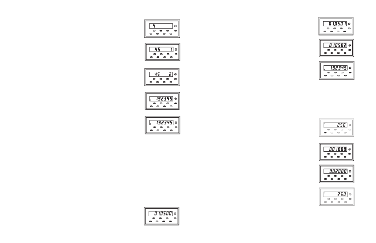
Entering function and mode is easily accomplished by
pressing the appropriate digit key. To program the Scale
Multiplier, you would enter 45 by pressing the front panel
keys, 4 and 5.
The digits on the left side of the display show the
function code; the digits on theright side showthe current
programmed mode.
A new mode selection is made by entering a new
number. On some of the entries, you have the option of a
plus “+” or minus “-” sign. In the cases where a “+” sign is
required, no sign will be displayed. If you do enter a “-”
sign (using the “+/-” key), a minus sign will be displayed
in front of the appropriate digit.
Pressing the “E” key finalizes the change. The display
will now show the count value immediately.
If you do not press the “E” key, the change will not be
recorded. The display will remain in the programming mode
for 15 seconds, and then return to normal operating mode
using the old function and mode settings.
The unit can be programmed with the factory settings by
calling up Function Code 41, putting a “-” in front of the
mode by pushing the “+/-” key, and entering it.
Refer to the “Factory Settings” section for more details.
PROGRAMMING THE PRESETS, SCALE FACTOR, TIMED
OUTPUTS & COUNTER LOAD VALUES
The Presets andScale Factor Values are commonly reprogrammed on adaily
basis. As such, single keystroke access has been provided on the front panel.
Pressing the “3” key will call up the Scale Factor.
Once the Scale Factor is displayed, changing the digits
can be accomplished by repeatedly pressing thekey beneath
the digit position you wish to change or by holding the key
down, allowing the digit to increment automatically.
The new value willbe entered when the “E” keyis pressed.
The internal unscaled Process and Total Count Values
are multiplied by the Scale Factor Value, which changes
the displayed values accordingly.
Presets 1 and 2 are assigned to the Process Counter and the Batch Preset is
assigned to the Batch Counter. To call up the Preset for the desired counter,
the Gemini 3300 must first be displaying that count value.
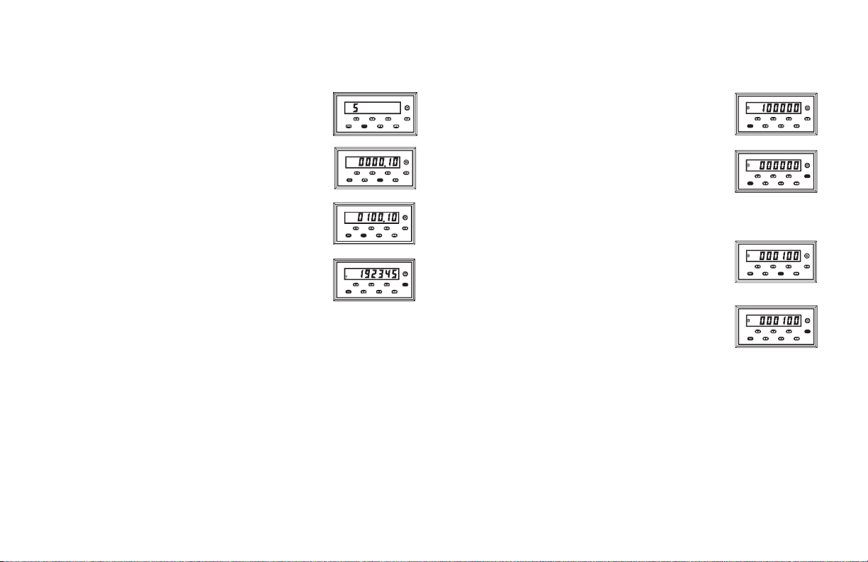
To display the Preset 1 Value (Process Counter),the
“+/-” key is first pushed (if necessary) until the “P”
(Process) annunciator is lit.
The “1” key is then pushed to call up the Preset 1 Value.
To change the value, the digits can be cycled through in
the same manner as discussed for the Scale Factors.
The new value willbe entered when the “E” keyis pressed.
The Preset 2 Value is changed in the same manner as
described above except that the “2” key is pushed instead
of “1”. To change the Batch Preset, the “1” key is pushed
while the Batch Counter is being displayed. The Preset
Values can range from 0 to +999999.
-4-
Page 7
The Timed Output Values are changed by entering two-digit function
codes. After the code is entered, the display will show the present Timed
Output 1, 2 or B Value in seconds with two decimal place resolution. The
Timed Output Values can be set from .01 to 599.99 seconds.
It is possibleto change thecounter values of the Gemini 3300 byentering a
“Counter Load Value”. This feature can be enabled or disabled by the
programming of the“Operator Accessible Functions Modes”, function code
66. The “Counter Load Value” is stored when the unit is powered down. To
access the Counter Load Value for the desired counter;
first, press the “+/-” key,if necessary,so that the display is
indicating the counter that is to be changed.
To change the Timed Output 1 Value, enter function
code 53 and enter the new value by holding down or
repeatedly pressing the key below the digit position you
wish to change.
The new value will be entered when the “E” key is
pressed. The display will immediately return to the
count value.
Note: A Timed Output Value of zero cannot be programmed into the Gemini
3300. If a value of0 is entered into the display, and the “E” keyis pressed,
the unit will remain in data entry mode. If a new value is not entered, it will
time out and the unit will continue to use its previous setting.
As with the other functions, you must press “E” to record the changes.For
the data entry modes, if you do not press the “E” key, a time out of 5 seconds
occurs, and the display returns to operating mode without any changes to the
value. The only time any change will occur is when the “E” key is pressed.
Secondly, press the “E” key and while holding it down,
press the “+/-” key.
The Gemini will now display the Counter Load Value
for the Counter that is displayed.
To change the value, press the key under the digit to be
changed as explained previously for the Preset.
To load the value into the counter, press the “E” key.
The display will flash momentarily and will display the
counter with the new value.
-5-
Page 8

FACTORY SETTINGS
INITIAL FACTORY CONFIGURATION
Keys Struck Display Description
4,3 43 1 Count with Inhibit
4,4 44 1 Count on falling edge of Input A
4,5 45 1 Scale Multiplier of 1.0
4,6 46 1 Leading zero blanking and no decimal point
5,2 52 5 Output 1 terminates after Timed Output, Normal Phase
5,3 0000.10 Timed Output 1 Value of 0.1 sec
5,4 54 5 Output 2 terminates after Timed Output, Normal Phase
5,5 0000.10 Timed Output 2 Value of 0.1 sec
6,1 61 4 Reset Process, Batch, and Total Counter
6,2 62 1 Process Counter, Manual Reset to Zero
6,3 63 1 Batch Counter, Manual Reset to Zero
6,4 64 3 Output B terminates at reset. Normal output phase
6,5 0000.10 Timed Output B Value of 0.1 sec
6,6 66 6 Presets, Scale Factor 2-Button Reset, & Counter
3 01.0000 Scale Factor set to 1.0000
1 000100 Preset 1 set to 100 (when Process Count displayed)
2 000200 Preset 2 set to 200 (when Process Count displayed)
1 000010 Preset B set to 10 (when Batch Count is displayed)
E & +/- 000000 Counter Load Values set to 0 (displays value for
Note: Entering a -1 in function code 41 will restore the unit to the factory configuration
shown above.
Load Programming Enabled
displayed counter)
-6-
Page 9

OPERATOR ACCESSIBLE FUNCTIONS WITH
PROGRAMMING DISABLED
(For details on keyboard entry, see preceding section)
One of the important features of the Gemini 3300 is the ability to disable
programming. With this ability, accidental bumping of the keys or tampering by
unauthorized personnel canbe prevented. However,it may be necessary toallow
reset and certain programming functions, such as Presets and the Scale Factor
Value, to be changed indaily operation. The Gemini3300, through theuse of the
“Operator Accessible Functions” Modes can enable these functions even when
the “PGM. DIS.” (Program Disable) terminal is connected to “COMMON”.
The “Operator Accessible Functions” modes areprogrammedby entering
a two-digit function code (66) and the desired mode. Unlike other function
codes, the mode doesnot take effect immediately. The “PGM. DIS.” terminal
must be connected to “COMMON” in order for the Gemini to disable
programming and operate as per the mode programmed.
There are six basic “Operator Accessible Functions” Modes available.
These modes enable the following functions.
1. NO FUNCTIONS ENABLED
2. PRESET PROGRAMMING ENABLED
3. SCALE FACTOR PROGRAMMING ENABLED
4. SCALE FACTOR AND PRESET PROGRAMMING ENABLED
5. PRESET, COUNTER LOAD PROGRAMMING, AND 2-BUTTON
RESET ENABLED
6. PRESET, SCALE FACTOR AND COUNTER LOAD PROGRAMMING,
AND 2-BUTTON RESET ENABLED
Note: In all of the modes above, the Reset button and terminal are enabled.
All of these modes can be modified with the addition of a “-” sign. The
minus sign disables the manual reset, at the front panel and the reset
terminal at the rear of the unit.
There is also a rear panel DIP switch which permits disabling of the front
panel reset button. This is independent of the rear reset terminal, and can be
used in conjunction with any front panel disable mode.
DIAGNOSTICS, SELF TEST, & “WATCHDOG” TIMER
The security of the Gemini 3300 is further enhanced by its self-test
diagnostic and “watchdog” timer capabilities.
The diagnostics are concerned with the special, no power memory of the
Gemini 3300. When power is turned off, all pertinent function settings and
measurements are automatically saved. When power is restored, the
functions and data are re-instated. This allows you to program the unit once
and not have to re-program it until you wish to use it in another mode.
When the function codes and data are saved, computations are made with
these values. The result of these computations is stored in the memory to
serve as a check against possible error. On power-up the same computations
are repeated on the stored data. If the results do not agree with the stored
results, a “P” will appear on the left side of the display. If thisoccurs, refer to
the “Troubleshooting Guide” for directions.
Another error indicator is the “watchdog” timer. In order to insure the
software is functioning properly, the program constantly monitors itself. If
the proper sequence and timing of internal events does not occur,an “E” will
appear on the left side of the display. If this occurs, refer to the
“Troubleshooting Guide” for directions.
The final type ofbuilt-in errorchecking is the front panelinitiated self-test.
It can beperformedat any time, evenwhen the Gemini 3300 is running. It will
not interfere withthe accumulation of counts or control functions.A function
code of “6”, “+/-” starts the test. At this time, whatever was displayed will
disappear and be replaced by a string of decimal points and the overflow
indicator. Then the display will show a string of 9’s, then 8’s etc., until a
string of 0’s are shown. The self-test will then turn off the overflow indicator
and activate the minus “-” sign. Then the unit shows an interlace pattern of
-010101, then -212121, followed by 232323 etc., until 898989 is reached. At
this time the outputs can be tested by pressing the “1” key for Output 1, the
“2” key for Output 2, and the “3” key for Output B.
(The program disable terminal must be disconnected in order to allow
activation of the outputs. Also, when testing theoutput, use caution, so as not
to cause any undesirable or hazardous conditions in the system.) An
automatic exit willtake place aftersix seconds or immediately if the Program
Disable terminal is connected to common. Normal length of display time for
each of the patterns is approximately 0.5 sec. Rapidly pressing “E” during
self-test can speed up the sequence.
-7-
Page 10

INPUT CIRCUITRY & SET-UP
There are two independent input channels on the Gemini 3300. Various
types of sensor outputs can be accommodated by appropriate DIP switch
set-up. These include: TTL orCMOS logic,currentsinking, current sourcing,
or dry contact and more.
Channel A consists of a logic input and a separate low level magnetic
pickup input.
Channel B is a completely independent count or control input channel.
Like Channel A, it canbe programmedwith DIP switches for awide variety of
logic inputs, and is identical to Channel A in this regard. For a complete
detailed description of input set-up, see Appendix “A”.
OVERFLOW INDICATION
The Gemini 3300 features an overflow indicator (LED) which is located to
the left ofthe sixth digitand above the polarity annunciator.This LED will turn
on if the capacity of the display (6-digits) is exceeded or if the internal count
capacity (9-digits, 7 digits for batch counter) is exceeded. Use of extremely
small scale multiplier and Scale Factor Value can cause the internal count
(Process and Total) capacity to overflow before the displayed value would
overflow. For example, if a Scale Factor of 0.0001 and a Scale Multiplier of
0.001 is used, for every 10,000,000 count edges received, the display would
increment by 1. Before the display reaches 215, the internal counter would
overflow. When the capacity of the display is exceeded, the countvalue will be
maintained and will be valid. But if the internal count capacity is exceeded,
then this value will no longer be valid. The internal Process and Total count
values will overflow after 2,147,483,647 counts have been entered. The count
information will become invalid after 4,294,967,295 counts. At this point the
counter will change sign and the displayed count will decrement in value.
The internal count capacity for the Batch Counter is 16,777,216. This
amounts to overflowing the Batch Counter display over 16 times. If this
number is exceeded, the counter will rollover to zero, however, thedisplayed
digits will no longer be valid. It should also be noted that the use of a Scale
Factor larger than one could cause the displayed Process or Total value to
overflow before 999,999 counts are accumulated.
The Batch and Totalizing counters should not be allowed to operate in the
overflowed condition. As soon as, or before the counters overflow, the
information should be recorded and the counters reset.
-8-
Page 11

PROGRAMMING INSTRUCTIONS FOR THE GEMINI 3300 BATCH COUNTER
The first part of this section provides detailed descriptions of the function
command codes for Input response modes, reset modes, output termination
modes, etc. Then, using an actual application example, the programming
instructions are “walked through” to give the user a full understanding of the
Gemini 3300 programming procedure. The descriptions below give the
function command code first, followedby the individual mode identifier. The
Function Command Summary in Appendix “D”, lists all codes.
CODE 41 - FACTORY SETTINGS
When Code 41 is called up, the unit will display a 1 as the mode.Entering a
“-” sign in front of the mode will cause the unit to re-load the factory settings
as shown in the “Factory Settings” section.
CODE 43 - INPUTS A & B RESPONSE MODES
The Gemini 3300 has six different input response modes that will directly
affect the Process Counter and the Total Counter. They are: Count (A) with
Inhibit (B); Count (A) with Up/Down Control (B); Two input
anti-coincidence Add (A)/Subtract (B); Two input anti-coincidence Add
(A)/Add (B); Quadrature; and Quadrature x4.
[43 1] COUNT WITH INHIBIT - Input A serves as the count. Input B serves
as the Inhibit input. When Input B is low, the counter will ignore the count
signal appearing at Input A. When Input B is at a high level, the signal
appearing on Input A will be counted. The “Process Counter Reset Action
Modes” will determine the count direction for the Process Counter. In
applications where the Inhibit function is not actually used, the Input B
“SRC/SNK” position of the “INPUT CONFIGURATION DIP SWITCH”
should be setto the “SNK” positionto provide a 7.8Kohm pull-up resistor.
This will set Input B to the Non-Inhibit state.
[43 2] COUNT WITH UP/DOWN CONTROL - In this mode,count direction
can be controlledby the second input.Input A serves asthe count input and
Input B serves as the direction control signal input.
When Input B is at a high level, the counter will count up. When Input B is
at a low level, the counter will count down.
[43 3] TWO INPUT ANTI-COINCIDENCE ADD/SUBTRACT - This mode
effectively separates count pulses which may simultaneously appear at the
two inputs. The Gemini unit processes the count pulses into a string of
time-separated pulses, so the internal counter will not lose any count
pulses. Input A serves as the add input (count increments) and Input B
serves as the subtract input (count decrements).
[43 4] TWO INPUT ANTI-COINCIDENCE SUMMING - Input A and B are
summed or added in the same manner as above. This mode is
uni-directional. The “Process Counter Reset Action Modes”, will
determine the count direction for the Process Counter.
[43 5] QUADRATURE COUNTING - Quadrature counting modes are
primarily used in positioning and anti-jitter applications. The reason this
mode works is due to the manner in which two pickups are positioned
relative to each other. The signal on Input B is a pulse train signal shifted
90° away from the Input A signal. These two signals are processed by the
Gemini as follows:
Input A serves as the count, while Input B serves as the quadrature input.
For quadrature with single edge counting, the counter will count in a
positive direction when Input A is a negativegoing edge andInput B is at a
low level. The counter will count in a negative direction when Input A is a
positive going edge and InputB is at a low level. All transitionson Input A
are ignored when Input B is at a high level. These logic rules provide the
basis for anti-jitter operation which will prevent false counts from
occurring due to back-lash, vibration, chatter, etc.
When two edge counting is used, the quadrature mode works the same as
with single edge counting when Input B is low. But when Input B is at a
high level, counts at Input A are no longer ignored. Instead the logic rules
for Input A are complemented, allowing both edges of Input A to be
counted. This doubles the effective resolution of the encoded input.
-9-
Page 12

CODE 43 - INPUTS A & B RESPONSE MODES (Cont’d)
[43 6] QUADRATURE TIMES 4- This modetakes the quadraturemode, with
two edgecounting, one step further. In quadrature times 4, both Input A and
Input B serve as the count or quadrature input, depending on their state. In
one instance, Input A will serve as the count input and Input B will serve as
the quadrature input. In another instance, Input A will be the quadrature
input and Input B will be the count input. This enables each edge, positive
and negative going, of both inputs, A and B, to be counted. This results in a
resolution four times greater than in the basic quadrature x1 mode.
CODE 44 - NUMBER OF COUNT EDGES
The Gemini 3300 can be programmed for either single (negative going edge)
or two edge (x2) counting. The number of count edges cannot be set when the
count mode is programmed for quadrature x4 operation. The Gemini will ignore
any attempt to enter Function Command Code 44 when set for quadrature x4.
[44 1] SINGLE EDGE COUNTING (x1) - The unit counts on the negative
going (falling) edge of the count input signal.The count mode descriptions
describe how each mode uses this method of edge counting.
[44 2] TWOEDGE COUNTING (x2) - This mode is used whendoubling of the
count signal input isrequired. The unit counts on the positive going (rising)
edge of the countinput signal,as well as the negativegoing (falling)edge.
CODE 45 - SCALE MULTIPLIER
There are four Counter B Scale Multipliers that are available. They
effectively divide the internal Process and Total Count Values by 1, 10, 100,
and 1000 respectively, to yield the displayed values. (Note: Use of a small
scale multiplier in conjunction with a small Scale Factor could cause the
internal count value to be exceeded before the 6-digit display value is
exceeded.) See “Overflow Indication” section for more details.
[45 1] x1
[45 2] x 0.1
[45 3] x0.01
[45 4] x0.001
CODE 46 - DECIMAL POINT & LEADING ZERO BLANKING
There are six basic modes of decimal point placement for the Process and
Total counter of the Gemini 3300. The decimal point is placed to the right of
the display digit that corresponds to the mode identifier. (The right most
decimal point, digit 1, is never turned on.) A “-” sign in front of the mode
identifier will inhibit leading zero blanking. The absence of a “-” sign will
enable leading zero blanking.
[46 1] 0
[46 2] 0.0
[46 3] 0.0 0 LEADING ZERO
[46 4] 0.0 0 0 BLANKING
[46 5] 0.0000
[46 6] 0.00000
[46-1] 000000
[46-2] 00000.0
[46-3] 0000.00 LEADINGZERO
[46 -4] 0 0 0.0 0 0 BLANKING INHIBITED
[46-5] 00.0000
[46-6] 0.00000
CODE 52 - OUTPUT 1 TERMINATION MODES
The Gemini 3300 has five “Output 1 Termination Modes”, which control
the way Output 1 (O1) will terminate or reset. An Output 1 response will
occur when theProcess Counter reaches the Preset 1 Value (when counting in
the “normal” count direction). In all modes, Output 1 will terminate
immediately when the Process counter is manually reset.
A reverse phase mode is available on the Gemini 3300. This refers to the
complementing of the logic state of the output. With normal phase operation,
when the Process counter value reaches Preset 1, Output 1 will turn on. The
reset condition of Output 1is output off. In reverse phase operation, Output 1
turns off when Preset 1 is reached. The reset condition of Output 1 is output
on. (Note: The state of the relay, if used, is also reversed.) A “-” sign in front
of the mode identifier will provide for reverse phase operation. The absence
of a “-” sign will indicate normal phase operation.
-10-
Page 13

[52 1] TERMINATE AT OUTPUT 2 START - Output 1 (O1) will terminate
when Output 2 starts. Output 1 is set for normal phase operation.
[52 2] TERMINATE AT OUTPUT 2 END - Output 1 (O1) will terminate
when Output 2 ends. Output 1 is set for normal phase operation.
[52 3] TERMINATE AT MANUAL RESET - Output 1 (O1) activates when
the Process Counter Value reaches the Preset 1 value. In this mode, once
Output 1 is activated,itdoes not deactivate untilthe moment amanualreset
occurs. Output 1 is set for normal phase operation.
[52 4] TERMINATE AT MANUAL RESET END - This mode is like the
preceding, except Output 1 (O1) deactivates when manual reset ends.
Output 1 is set for normal phase operation.
[52 5] TERMINATE AFTER TIMED OUTPUT 1 - Once Output 1 (O1) has
been activated, it will deactivate after the predetermined length of time
(Code 53) has expired. Manual reset will override the timed output and
reset Output 1. Output 1 is set for normal phase operation.
[52 -1]
[52 -2]
[52 -3] These modes are the same as above with the exception
[52 -4] that the output is set for reverse phase operation.
[52 -5]
CODE 53 - TIMED OUTPUT 1 VALUE
The Gemini 3300 has the capability of varying the Timed Output 1 Value
from 0.01 second to 599.99 seconds. When the code is entered, instead of a
single mode identifier digit beingdisplayed, six digits willbe shown.Refer to
“Programming the Presets, Scale Factor, Timed Outputs & Counter Load
values” section for more details about entering. The timed output will be
terminated if the Process counter is manually reset.
Note: A Timed Output value of zero cannot be programmed into the Gemini
3300. If a value of 0 is entered into the display and the “E” key is pressed,
the unit will not enter the 0, but will stay in the data entry mode. If a new
value is not entered, it will time out and the unit will continue to use its
previous setting.
CODE 54 - OUTPUT 2 TERMINATION MODES
The Gemini 3300 has five “Output 2 Termination Modes”,which control the
way Output 2 (O2) will terminate or reset.An Output 2response will occurwhen
the Process Counterreaches the Preset 2 value orzero. In all modes, Output2 will
terminate immediately when the Process Counter is manually reset.
A reverse phase mode is available on the Gemini 3300. This refers to the
complementing of the logic state of the output. With normal phase operation,
when the Process counter value reaches Preset 2, Output 2 will turn on. The
reset condition of Output 2is output off. In reverse phase operation, Output 2
turns off when Preset 2 is reached. The reset condition of Output 2 is output
on. (Note: The state of the relay, if used, is also reversed.) A “-” sign in front
of the mode identifier will provide for reverse phase operation. The absence
of a “-” sign will indicate normal phase operation.
[54 1] TERMINATE AT OUTPUT 1 START - Output 2 (O2) will terminate
when Output 1 starts. Output 2 is set for normal phase operation.
[54 2] TERMINATE AT OUTPUT 1 END - Output 2 (O2) will terminate
when Output 1 ends. Output 2 is set for normal phase operation.
[54 3] TERMINATE AT MANUAL RESET - Output 2 (O2) activates when
the Process Counter reaches the Preset 2 value or zero. In this mode, once
Output 2 is activated,itdoes not deactivate untilthe moment amanualreset
occurs. Output 2 is set for normal phase operation.
[54 4] TERMINATE AT MANUAL RESET END - This mode is like the
preceding, except Output 2 (O2) deactivates when manual reset ends.
Output 2 is set for normal phase operation.
[54 5] TERMINATE AFTER TIMED OUTPUT 2 - Once Output 2 (O2) has
been activated, it will deactivate after the predetermined length of time
(Code 55) has expired. Manual reset will override the timed output and
reset Output 2. Output 2 is set for normal phase operation.
[54 -1]
[54 -2] These modes are the same as above with the exception
[54 -3] that the output is set for reverse phase operation.
[54 -4]
[54 -5]
-11-
Page 14

CODE 55 - TIMED OUTPUT 2 VALUE
The Gemini 3300 has the capability of varying the Timed Output 2 Value
from 0.01 second to 599.99 seconds. When the code is entered, instead of a
single mode identifier digit beingdisplayed, six digits willbe shown.Refer to
“Programming the Presets, Scale Factor, Timed Outputs & Counter Load
Values” section for more details about entering. The timed output will be
terminated if the Process Counter is manually reset.
Note: A Timed Output Value of zero cannot be programmed into the Gemini
3300. If a value of 0 is entered into the display and the “E” key is pressed,
the unit will not enter the 0, but will stay in the data entry mode. If a new
value is not entered, it will time out and the unit will continue to use its
previous setting.
CODE 61 - RESET BUTTON & TERMINAL ACTUATION
MODES
Since there are three counters integrated intothe Gemini 3300,various modes
are available to provide the desired reset response to the activation of the front
panel Reset button, “R”, or rear “RST” terminal. The mode selected, determines
which counter(s) will reset when the reset button or terminal is activated.
There are two ways the manual reset can act on the unit. The first is a
“maintained” reset action, in which the unit is held reset as long as the reset
button or terminal is activated. If the Process Counter is held in “maintained”
reset, counting on all three counters will be inhibited. The second is a
“momentary” action in which the unit resets and starts counting immediately,
even though the reset button or terminal may still be activated. A “-” sign
preceding the mode identifier indicates “momentary” reset action. The absence
of a “-” sign indicates “maintained” reset action.
[61 1] RESET PROCESS COUNT ONLY
[61 2] RESET BATCH COUNT ONLY
[61 3] RESET PROCESS AND BATCH COUNT
[61 4] RESET PROCESS, BATCH AND TOTAL COUNT
[61 -1]
[61 -2] These modes are the same as above with the exception
[61 -3] that reset is set for “Momentary” operation.
[61 -4]
CODE 62 - PROCESS COUNTER RESET ACTION & PRESET
TRACKING MODES
The “Process Counter Reset Action Mode” determines how the Process
Counter can be reset and the type resetaction thatwill occur. In the manual reset
modes, reset can only occurby activation of the Reset button, resetterminal (See
“Reset Button & Terminal Actuation Modes” - Code 61), 2-button reset, or
through serial communications. In the “Auto Reset” modes the Process Counter
can be reset manually and canalso be resetwhen the ProcessCounter reaches the
Preset 2 value, orzero,or after Timed Output 2,depending onthe mode selected.
A Preset tracking mode is also incorporated in Function Code 62. A “-”
sign preceding the reset action mode indicates that Preset tracking is enabled.
The absence of a “-” sign indicates that Preset tracking is disabled.
If Preset tracking is enabled, whenever the Preset 2 value is changed, the
Preset 1 valuewill also change so that the offsetbetween Preset 2 and Preset
1 remains the same. The amount of offset is changed by changing the Preset
1 value. For example, if Preset 2 is 100 and it is desired that Preset 1 occurs
20 counts before Preset 2, thePreset 1 value would be set to 80. If Preset 2 is
then changed to200, Preset 1 will automatically change to 180, maintaining
the same 20 count offset.
The Preset 1 Value cannot be changed when Preset tracking is enabled and
the “PGM.DIS.” (Program Disable) terminal isconnected to“COMMON”.
[62 1] MANUAL RESET TO ZERO - Manualreset to zero is accomplished by
pulling the “RST.” terminal to “COMMON” or, if the front panel reset is
enabled, bypressing the front panel resetbutton, or by using the “Two Button
Reset” (pressing the “E” key and the “1” key). Preset tracking is disabled.
[62 2] MANUAL RESET TO PRESET 2 - Manual reset to Preset 2 is
accomplished by pulling the “RST.” terminal to “COMMON” or, if the
front panel reset is enabled, by pressing the front panel reset button, or by
using the “Two Button Reset” (pressing the “E” key and the “1” key).
Preset tracking is disabled.
[62 3] AUTOMATIC RESET TO ZERO AFTER TIMED OUTPUT 2 - The
Process Counter automatically resets to zero when Timed Output 2 ends.
The “Output 2 Termination Mode” should be programmed for timed
output operation, [54 5], when in this mode. Preset tracking is disabled.
-12-
Page 15

[62 4] AUTOMATIC RESET TO PRESET 2 AFTER TIMED OUTPUT 2 -
The Process Counter automatically resets to Preset 2 when Timed Output 2
ends. The “Output 2 Termination Mode” should be programmed for timed
output operation, [54 5], when in this mode. Preset tracking is disabled.
[62 5] AUTOMATIC RESET TOZERO AT THEBEGINNING OF TIMED
OUTPUT 2 (AT PRESET 2) - In this reset mode, the Process Counter will
automatically reset to zero at the beginning of Timed Output 2 (at Preset
2). The Timed Output 2 Value (Code 55) must be shorter than the time
required for the counter to count to the Preset 2 Value, otherwise, Output 2
will appear to be latched on. The “Output 2 Termination Mode” should be
programmed for timed output operation, [54 5], when in this mode. Preset
tracking is disabled.
[62 6] AUTOMATIC RESET TO PRESET 2 AT THE BEGINNING OF
TIMED OUTPUT 2 (AT ZERO) -In this resetmode, the ProcessCounter will
automatically reset to Preset 2 at the beginning of Timed Output 2 (at zero).
The Timed Output 2 Value (Code 55) must be shorter than the time required
for the counter to count to zero, otherwise, Output 2 will appear to be latched
on. The “Output 2 Termination Mode” should be programmed for timed
output operation, [54 5], when in this mode. Preset tracking is disabled.
[62 -1]
[62 -2]
[62 -3] These modes are the same as above with the exception
[62 -4] that Preset Tacking is enabled.
[62 -5]
[62 -6]
CODE 63 - BATCH COUNTER RESET ACTION MODES
The “Batch Counter Reset Action Mode” determines how the Batch Counter
can bereset and thetype reset action that willoccur. In themanual reset modes, the
Batch Counter can only be reset by activation of the Reset button, reset terminal
(See “Reset Button & Terminal Actuation Modes” - Code 61), 2-button reset, or
through serial communications. In the “Auto Reset”modes,the Batch Countercan
be reset manually and can also be reset when the Batch Counter reaches the Batch
Preset value or zero (reset to Preset modes), or after the Batch Timed Output.
[63 1] MANUAL RESET TO ZERO - Manual reset to zero is accomplished
by pulling the “RST.” terminalto “COMMON”or, if the front panelreset is
enabled, by pressing the front panel reset button, or by using the “Two
Button Reset” (pressing the “E” key and the “2” key).
[63 2] MANUAL RESET TO BATCH PRESET - Manual reset to Batch
Preset is accomplished by pulling the “RST.” terminal to “COMMON” or,
if the front panel reset is enabled, by pressing the front panel reset button,
or by using the “TwoButton Reset”(pressingthe “E” key and the“2”key).
[63 3] AUTOMATIC RESET TOZERO AFTER BATCH TIMED OUTPUT
- The Batch Counterautomatically resets to zero when Batch Timed Output
ends. The “Batch Output Termination Mode” should be programmed for
timed output operation, [64 5], when in this mode.
[63 4] AUTOMATIC RESET TO BATCH PRESET AFTER BATCH TIMED
OUTPUT - The Batch Counter automatically resets to Batch Preset when
Batch Timed Output ends. The “Batch Output Termination Mode” should be
programmed for timed output operation, [64 5], when in this mode.
[63 5] AUTOMATIC RESET TOZERO AT THE BEGINNING OFBATCH
TIMED OUTPUT (AT BATCH PRESET) - In this reset mode, the Batch
Counter will automatically reset to zero at the beginning of Batch Timed
Output (at Batch Preset). The Batch Timed Output Value (Code 65) must
be shorter than thetime required for thecounter to count to theBatch Preset
Value, otherwise, the Batch Output will appear to be latched on. The
“Batch Output Termination Mode” should be programmed for timed
output operation, [64 5], when in this mode.
[63 6] AUTOMATIC RESET TO BATCH PRESET AT THEBEGINNING OF
BATCH TIMED OUTPUT (AT ZERO) - In this reset mode, the Batch Counter
will automatically reset to Batch Preset at the beginning of Batch Timed Output
(at zero). The Batch Timed Output Value (Code 65) must be shorter than the
time required for the counter to count to zero, otherwise, the Batch Output will
appear to be latched on. The “Batch Output Termination Mode” should be
programmed for timed output operation, [64 5], when in this mode.
CODE 64 - BATCH OUTPUT TERMINATION MODES
The Gemini 3300 has three “Batch Output Termination Modes”,which
control the way Batch Output (OB) will terminate or reset. A Batch Output
response will occurwhen the BatchCounter reaches theBatch Preset value or
zero. In all modes, the Batch Output will terminate immediately when the
Batch Counter is manually reset.
-13-
Page 16

CODE 64 - BATCH OUTPUT TERMINATION MODES (Cont’d)
A reverse phase mode is available on the Gemini 3300. This refers to the
complementing of the logic state of the output. With normal phase operation,
when the Batch counter value reaches the BatchPreset, the Batch Output will
turn on. The resetcondition of the BatchOutput isoutput off. In reversephase
operation, the Batch Output turns off when the Batch Preset is reached. The
reset condition of the Batch Output is output on. A “-” sign in front of the
mode identifier will provide for reverse phaseoperation. The absence ofa “-”
sign will indicate normal phase operation.
[64 3] TERMINATE AT MANUAL RESET - The Batch Output (OB)
activates when theBatch Counterreaches the Batch Presetvalue or zero. In
this mode, once the Batch Output is activated, it does not deactivate until
the moment a manual reset of the Batch Counter occurs. The Batch Output
is set for normal phase operation.
[64 4] TERMINATE AT MANUAL RESET END - This mode is like the
preceding, except the Batch Output (OB) deactivates when manual reset
ends. The Batch Output is set for normal phase operation.
[64 5] TERMINATE AFTER TIMED BATCH OUTPUT - Once the Batch
Output (OB) hasbeen activated, it willdeactivate after the predetermined
length of time (Code 65) has expired. Manual reset will override the
timed output and reset the Batch Output. The Batch Output is set for
normal phase operation.
[64 -3] These modes are the same as above with the exception
[64 -4] that the output is set for reverse phase operation.
[64 -5]
CODE 65 - BATCH TIMED OUTPUT VALUE
The Gemini 3300 has the capability of varying the Batch Timed Output
Value from 0.01 second to 599.99 seconds. Whenthe code is entered, instead
of a single mode identifier digit being displayed, six digits will be shown.
Refer to “Programming the Presets, Scale Factor, Timed Outputs & Counter
Load Values” section for more details about entering. The timed output will
be terminated if the Batch Counter is manually reset.
Note: ATimed Output Value of zerocannot be programmed into theGemini 3300.
If a value of 0is entered into the displayand the “E”key is pressed,the unit will
not enter the 0, but willstay in thedata entry mode.If a newvalue is not entered,
it will time out and the unit will continue to use its previous setting.
CODE 66 - “OPERATOR ACCESSIBLE FUNCTIONS” MODES
The Gemini 3300 hassix basiclevels of “Operator AccessibleFunctions”.
Each of these levels can be modified to enable or disable manual reset. When
the “PGM. DIS.” (Program Disable) terminal is connected to “COMMON”,
access to all functions is disabled except for those listed below which will
remain enabled. All ofthe function codes and parameters can be interrogated,
regardless of the “Operator Accessible Functions” mode selected.
A “-” sign in front of the mode identifier will disable the front panel Reset
button and the “RST.” terminal.
Note: The frontpanel reset button can beindependently disabled by usingthe
disable reset DIP switch.
[66 1] NOFUNCTIONS ENABLED EXCEPT RESET - In this mode, manual
reset is enabled, but none of the programming functions can be changed.
[66 2] PRESET PROGRAMMING AND RESET ENABLED - In this mode,
manual reset and the programming of the Preset Values are enabled.
[66 3] SCALE FACTOR PROGRAMMING AND RESET ENABLED - In
this mode, manual reset and the programming of the Scale Factor Value
are enabled.
[66 4] SCALE FACTOR, PRESET PROGRAMMING AND RESET
ENABLED - In this mode, manual reset and the programming of the Scale
Factor and Preset Values are enabled.
[66 5] PRESET, COUNTER LOAD PROGRAMMING, 2-BUTTON RESET
AND RESET ENABLED - In this mode,manual reset and the programming
of the Presets, Counter Load Values and 2-Button Reset are enabled.
[66 6] PRESET, SCALE FACTOR, COUNTER LOAD PROGRAMMING,
2-BUTTON RESET AND RESET ENABLED - In this mode, manual reset
and the programming of the Presets, Scale Factor, Counter Load Values
and 2-Button Reset are enabled.
[66 -1]
[66 -2]
[66 -3] These modes are the same as above with the exception
[66 -4] that manual reset (Reset Button & Terminal) is disabled.
[66 -5]
[66 -6]
-14-
Page 17

PRESET VALUES
The Gemini 3300 has three Preset values. Two Presets are assigned to the
Process counter and one is assigned to the Batch counter. Whenever the
counter value equalsthe preset value assigned to the display,an output action
will occur. This action depends on the previously programmed modes. The
preset values may range from 0 to 999,999. (Refer to “Programming the
Presets, Scale Factor, Timed Outputs & Counter Load Values” section for
instructions on entering the preset values.)
The Scale Factor will have a direct effect on the Process Counter preset
value being entered. For a Scale Factor Value greater than one, the preset
value should be an integer multipleof the ScaleFactor. If itis not, theGemini
will automatically adjust the preset value up or down to force it to be evenly
divisible by the Scale Factor.
WITH PROCESS COUNT DISPLAYED -
“1” - PRESET 1 VALUE
“2” - PRESET 2 VALUE
WITH BATCH COUNT DISPLAYED -
“1” - BATCH PRESET
SCALE FACTOR
“3” SCALE FACTOR -TheScale Factor is accessed bypressing the “3” key.
The number of pulses counted (internal Process and total count values) is
multiplied by the Scale Factor, and scale multiplier which will change the
displayed value accordingly. A Scale Factor Value of 1.0000 and a Scale
Multiplier of 1 would result in a display of the actual number of inputpulses
that have been counted. The Scale Factor is used primarily for conversion
from existing pulses perunit of measure to the required displayedunits. This
includes conversion from different unitsof measure(i.e feet tometers, etc.).
The Scale Factor Value may range from 0 to +5.9999. Refer to
“Programming the Presets, Scale Factor, Timed Outputs & Counter Load
Values” section for entering instructions. It is important to note that the
precision of a counter application cannot be improved by using a Scale
Factor greater than one. To accomplish greater precision, more pulse
information must be generated per measuring unit. For example, if 5 pulses
are being receivedper footof material, the precision of10th of feet cannotbe
attained by simply programming a Scale Factor of 2.0000, even though the
display is readingin 10ths. Inthis case, thedisplay will increment by two for
each count input.Thus if anodd Preset Value wasentered, such as6.7 ft., the
Gemini will alter the preset to read in even tenths of feet.
Note: Use of a small Scale Factor in conjunction with a small scale
multiplier could causethe internal countvalue (Process or Total Counter)
to be exceeded before the 6-digit counter value is exceeded.
COUNTER LOAD VALUES
The Counter Load Valuesare provided to allow theuser tomodify the three
counter values. The CounterLoad Values of theGemini 3300are stored in the
unit’s non-volatile memory upon power down. Accessing the Counter Load
Value for the counter that is currently being displayed is accomplished by
pushing the “E” button, and while holding it down, also pushing the “+/-”
button. See “Programming the Presets, Scale Factor, Timed Outputs &
Counter Load Values” section for entering instructions.
“E” & “+/-” - Counter Load Value for the currently displayed counter.
-15-
Page 18

PROGRAMMING EXAMPLE
This example depicts a typical application for the Gemini 3300. The
programming steps and set-up will be discussed to give the user an
understanding on how to configure the Gemini 3300.
A typical industrial application for the Gemini 3300 will require a slow down
output, a final stop output, and an end of batch output. The Gemini 3300 can be
easily programmed to solve this requirement. Let’s look at a textile web process
that requires two outputs as the webprogresses to the properlength and an output
when the desirednumberof rolls hasbeen processed. A typical lengthof material
for this application is 1,000 feet. A slow down output is needed approximately
100 feet prior to the end of the 1000 foot length. After 100 rolls of material have
been processed, the power to the motor drive will be removed to prevent further
processing until the unit is reset. A light will also be turned on to indicate to the
operator that the run has been completed.
There are a coupleof ways to set-up the Process Counter of theGemini3300.
The Process Countercould be set-up for “ManualReset to Preset 2” operation.
Preset 2 wouldbe set to thetotal length of1000 and Preset 1would be setto 100
(the distance before final cut where the slow down output is to occur).Ifthe
total length were to change, only Preset 2 would need to be changed. Preset 1
would remain set to 100. If the Process Counter is set up for “Reset to Zero”
operation, Preset 2 would still be set to 1000, however Preset 1 would need to
be set to 900 (1000-100), so that the slow down output would still occur 100
feet before final cut. Normally in up-counting modes this type of application
would require that Preset 1 be changed along with Preset 2 every time a
different length was to be processed. With the Gemini 3300, this is not
necessary. The Gemini 3300 has a “Preset tracking” feature which causes
Preset 1 to track Preset 2 whenever the Preset 2 value is changed. In this
application we choose to utilize the second method of setting up the Process
Counter, using “Reset to Zero” operation with “Preset Tracking”.
The Batch Counter can also be set-up for “Reset to Zero” or “Reset to
Preset” operation.
The accompanying drawing showsan LMPC sensing a60 tooth gear which
is attached to a2.5 ft.circumference drum. The desired units ofdisplay willbe
feet. Since there is more than one pulse per foot of travel, the pulses input to
the Gemini will need to be scaled.
-16-
Page 19

SCALING THE COUNTER
In order toscale the counter, theprocedure and formulas in Appendix “E” “Scaling for Counting” are used.
In converting pulse units to “Display Units”, itis known that60 pulses are
equivalent to 1 revolution of the feed roll, which is equivalent to 2.5 feet
linear travel of the wire screen. The number of “Display Units”, therefore is
2.5 and the “Number of Pulses” per 2.5 display units is 60.
STEP 1 - Calculate the Total Scaling Factor, “K
Appendix “E”.
K
= Display Units/Number of Pulses
T
K
= 2.5/60 = 0.0416667
T
”, using Formula #1 of
T
STEP 2 - Determine the Number of Count Edges, “NCE”, necessary for this
application, and calculate the Remaining Scaling required, “K
Formula #2 of Appendix “E”.
Since the Total Scaling Factor, “K
can be used, therefore, the Number of Count Edges, “NCE”, is 1.
K
= 0.0416667/1 = 0.0416667
R
”, is less than 1, single edge counting
T
K
=KT/NCE
R
”, using
R
STEP 3 - Determine the Scale Multiplier Value, “SCM”, and calculate the
Scale Factor, “SF”, using Formula #3 of Appendix “E”.
A Scale Multiplier value of 0.01 ischosen to provide the maximum number
of significant digits in the Scale Factor.
SF = KR/SCM
SF = 0.0416667/0.01 = 4.1667
HARDWARE SET-UP
The application drawing shows how the hardware for this system is to be
connected. The red, black, and white wires of the LMPC are connected to the
DC OUT, COMM., and INPUT A terminals respectively. The shield of the
LMPC cable is also connected to COMM. A remote reset button is connected
between the RST. and COMM. terminals. After the programming is
completed, a jumper is placed between the PGM.DIS. and COMM. terminals
of the Gemini 3300. This terminal, in conjunction with the “Operator
Accessible Functions” mode, will prevent accidental changes in the unit’s
operating modes. The Normally Open contact of Relay 1 is connected to the
slow down actuatorand the Normally Opencontact of Relay 2 is connected to
the motor control. A 12 VDC external relay (RLC # RLY10000) is used to
deactivate the motor drive control and turn on the indicator light.
DIP switch 1 is set to the logic position. This allows Input A to function as
the count input. Switch position 2 is set to SNK. (current sinking),which
provides an internal pull-up resistor to 12 VDC. Position 3 is set to HI FRQ.
because of the high count speeds involved. Position 4 is set to HI BIAS for
higher noise immunity.
In thisapplication, the “Count with Inhibit” Inputs A & B Response mode
will be used. The application will not use the inhibit function, so Input B will
be set-up in the non-inhibiting state.
STEP BY STEP PROGRAMMING OF THE GEMINI 3300
Refer to the “Programming the Gemini 3300” section for instructions on
programming the function codes and entering the Scale Factor and Presets.
STEP 1 - Enter Code 43 (Inputs A & B Response Modes), and enter a mode
identifier of 1 (Input A = Count, Input B = Inhibit).
STEP 2 - Enter Code 44 (Number of Count Edges), and enter a 1 for single
edge counting.
STEP 3 - Enter Code 45 (Scale Multiplier), and enter a mode identifier of 3
for a Scale Multiplier of 0.01.
STEP 4 -Enter Code46 (Decimal Point and LeadingZero Blanking),andenter
a mode identifier of 1 for no decimal points with Lead Zero Blanking.
STEP 5 - Enter Code 52 (Output 1 Termination Modes),andentermode
identifier of 3 forterminate at start of manual reset. Output1 is the slow down
output, which once activated,should remain so until theunit ismanuallyreset.
STEP 6 - Enter Code 54 (Output 2 Termination Modes), and enter a mode
identifier of -3 (terminate at start of manual reset, reverse phase
operation). This mode was selected so that when the systemis powered up,
the relay would be in the open condition which is motor drive off. To start
the process, the Reset button is pushed which would close the Output 2
Relay (turn on motordrive) and would stayclosed until Preset 2is reached,
at which time it would open (turn motor drive off).
STEP 7 - Enter Code 61 (Reset Button and Terminal Actuation Modes),and
enter a mode identifierof 1 (Reset Process Counter). Withthis mode,when
the Reset buttonis pushed, only theProcess Counter will reset.To reset the
Batch or TotalCounters, the two buttonreset, or Total CounterLoad Value
must be utilized.
-17-
Page 20

STEP BY STEP PROGRAMMING OF THE GEMINI 3300 (Cont’d)
STEP 8 - Enter Code 62 (Process Counter ResetAction Modes),andentera1
(Manual Reset to Zero with Preset Tracking enabled).
STEP 9 - Enter Code 63 (Batch Counter Reset Action Modes),andentera2
(Manual Reset to Batch Preset).
STEP 10 - Enter Code 64 (Batch Output Termination Modes),andentera
mode identifier of 3 (Terminate at Manual Reset).
STEP 11 - Enter Code 66 (“Operator Accessible Functions” Mode),and
enter a mode identifier of 5, (Preset, Counter Load programming,
2-Button Reset and Reset enabled). When the “PGM. DIS.” (program
disable) terminal is connected to COMMON, the only changes that will be
possible is resetting the unit andchanging Preset 2and Preset B.Preset 1 is
locked out when Preset tracking is enabled. The Preset 1 value should be
entered before “PGM. DIS.” terminal is connected to COMMON.
STEP 12 -Pressthe“+/-” key until the Process Count is displayed (P
annunciator is displayed).Press“1” and enter the value at which the
machine is to start slowing down (900 is used in this application).
STEP 13 -Press“2” and enter the total length of material to be processed
(1000 feet).
STEP 14 -Pressthe“+/-” key until the Batch Count Value is displayed (B
annunciator is displayed).Press“1” andenter the amount of spools to be
wound.
STEP 15 -Press“3” and enter a Scale Factor Value of 4.1667
STEP 16 - Connect the “PGM. DIS.” terminal to “COMM.” to prevent
accidental changes to the program modes.
-18-
Page 21

GEMINI 3300 20 MA CURRENT LOOP COMMUNICATIONS
The Gemini 3300’s 20 mA Current Loop CommunicationsOption allows a
“two-way” serial communications link to be established in order to monitor
or change the countervalues, Presetsand ScaleFactor from a remote location.
Some typical devices that can be connected with the Gemini 3300 are: a
printer, terminal, programmable controller, or host computer. For devices
that use RS232, a GCM232 Serial Converter Module is available to convert
the 20 mA Current Loop signals to RS232 and vice-versa.
There are two loopsthat mustbe established.One for sending commands to
the Gemini 3300 and one for receiving thedata values from the Gemini 3300.
Up to sixteen Geminis or other RLC units with 20 mA serial communication
capability, can be connected together in the “loop” if a 24 V external current
source is utilized.A maximumof seven unitscan be installed inthe loop ifthe
Gemini’s 20 mA current source is used. The units are assigned addresses by
setting the Serial DIP Switches on each unit. The applications can be as
simple as attaching a printer to obtain hard copy of the display information or
as involved asusing a host computerto automatically set upPresets and Scale
Factors on a number of Geminis.
With the Communications Option, thefollowing functionscan be performed:
1. Interrogation of the Count Values, Presets, and Scale Factor.
2. Changing of the Count Values, Presets and Scale Factor.
3. Resetting of the Count Values and Outputs.
4. Changing the viewed display value.
5. Automatic print-out when using a printer and the “Print Request”
Terminal.
COMMUNICATION FORMAT
Data is sent by switching off and on the current in the 20 mA current loop.
Data is received by monitoring the switching action and interpreting the
codes that are transmitted. In order for data to be interpreted correctly, there
must be identical formats and Baud Rates.
The format that the Gemini 3300 will accept is: 1 start bit, 7 data bits, 1
odd parity bit, and 1 stop bit. The Baud Rates that are available are: 300,
600, 1200 and 2400.
The selection of theBaud Rate is doneby setting DIP switches.Refer tothe
“Current Loop Installation” section, for set-up instructions.
FIG. 1: DATAFORMAT-10 BIT FRAME [300,600, 1200, 2400 Baud]
SENDING COMMANDS & DATA TO THE GEMINI 3300
When sending commands to the Gemini 3300, a command string must be
constructed. The command string may consist of command codes, value
identifiers, and numerical data. Following is a list of commands and value
identifiers that are used when communicating with the Gemini 3300.
COMMAND DESCRIPTION
N(4EH)
D (44H)
P (50H)
R (52H)
T (54H)
V (56H)
Address command; followed by a one or 2 unit address
number 1-15 and one of the following commands.
Change display command; followed by E, F, or G. This
command changes the viewed display channel on the
Gemini 3300 to “P” (Process Counter), “B” (Batch
Counter),or“T” (Total Counter).
Transmit per Print Options command.
Reset command; followed by a value identifier (E,F,or
G); operates on Process, Batch or Total Counter. A value
identifier of M: resets counter(s) currently selected in
Code 61.
Transmit Value command; followed by a value identifier
(A-G); operateson countervalues, Presets and ScaleFactors.
Change Value command; followed by a value identifier
(A-G); operates on countvalues, Scale Factor, and Presets.
-19-
Page 22

SENDING COMMANDS & DATA TO THE GEMINI 3300 (Cont’d)
VALUE
IDENTIFIER
A (41H)
B (42H)
C (43H)
D (44H)
E (45H)
F (46H)
G (47H)
M (4DH)
The command string is constructed by using the above commands and value
identifiers, along withthe data values that arerequired. Datavalues may or may
not contain the decimal point if a decimalpoint is programmed into the Gemini
3300. The Gemini 3300 will accept the decimal points, however, it does not
interpret them in any way. Leading zeros can be eliminated, however, all
trailing zeros must be present. For example, if a Scale Factor of 1.0000 is to be
sent, the data value can be transmitted as 1.0000 or 10000. If a “1” is
transmitted, the Scale Factor will be changed to 0.0001.
The Address command is used to allow a command to be directed to a
specific unit in the Serial Communications Loop. Whenever the unit address
is zero, transmission ofthe Address command is notrequired.This is done for
applications which do not require more than one Gemini. For applications
that require several units, it is recommended that each unit in the loop be
given a separate address. If they aregiven the same address, acommand such
as the Transmit Value Command, will cause all the units to respond at the
same time, resulting in erroneous data.
The command string is constructed in a specific logical sequence. The
Gemini 3300 will not accept command strings that do not follow this
sequence. Only one operation can be performed per command string. Below
is the procedure to be used when constructing a command string.
1. If the Gemini 3300, to which the command is to be sent, is assigned an
address other than zero, the first two or three characters of the command
string must consist of theAddress Command (N)and theaddress numberof
the unit (1-15).
DESCRIPTION MNEMONIC
Preset 1 (PS1)
Preset 2 (PS2)
Batch Preset (PSB)
Scale Factor (SCF)
Process Count (PRC)
Batch Count (BAT)
Total Count (TOT)
Counter (s) selected in Code 61 N/A
2. The next character(s) in the command string is the actual command that the
Gemini 3300 is to perform and the value identifier if it pertains to the
command. (A command such as the Transmit per Print Options, “P”,
command does not require a Value Identifier.)
3. If the change command is being used, the next characters in the command
string is the numerical data value.
4. The last character in the command string is the command terminator (*).
This character must be sent in order to tell the Geminis that the command
string is complete, so that they can begin processing the command.
Below are some typical examples of properly constructed command strings.
(EX. 1) Change Preset 1on the Gemini 3300 with anaddress of2 to 00123.4.
COMMAND STRING: N2VA1234*
(EX. 2) Have the Gemini 3300, with an address of 13, transmit the Batch
Count Value.
COMMAND STRING: N13TF*
As shown, all commands must be terminated with a “Command
Terminator” (* or 2AH). The Gemini 3300 will not process the command
until the terminator is sent. If illegal commands or characters are sent to the
Gemini 3300, they still would need to be terminated by an (*). If they are not
terminated, the next command will not be accepted.
When writing application programs inBasic, the transmission of spaces or
carriage return and line feed should be inhibited by using the semicolon
delimiter with the Printstatement. The Gemini 3300 willnot accept a carriage
return or line feed as valid characters.
When a “Change Value” command is sent to the Gemini 3300, a short
amount of time is required for the unit to process the data. This time increases
with the countrate. During this time,only one additional command maybe sent
to the Gemini 3300. This may be done 80 msec after the transmission of the
“Change Value” command. After the second command has been transmitted,
the unit will ignoreany further commands until 10 msecafter both the “Change
Value” and second command have been processed. It is recommended that a
“Transmit Value” command follow a “Change Value” Command. If this is
done, the reception of the data can provide a timing reference for sending
another command and will insure that the change has occurred.
-20-
Page 23

The timing diagrams show the timingconsiderations thatneed to be made.
FIG. 2: TIMING FOR SENDING COMMANDS
A typical transmission, with the “PR.ID” (Print ID) switchintheup
position, is shown below.
(**) This is the time that it takes the Gemini 3300 to process the preset.
It varies with the Count Rate and Scale Factor Value.
FIG. 3: TRANSMIT COMMAND TIMING
RECEIVING DATA FROM THE GEMINI 3300
Data is transmitted from the Gemini 3300 when a “Transmit Value” or
“Transmit per Print Options” command is sent to the unit, or when the “PRINT
REQ.” terminal is activated. The Gemini 3300 can transmit 7 values: display
channels P, B and T, Presets 1 & 2, Batch Preset and Scale Factor. A list of the
abbreviations used when theGemini3300 transmits the values areshown below.
PRC - Process Count Value
BAT - Batch Count Value
TOT - Total Count Value
PS1 - Preset 1
PS2 - Preset 2
PSB - Batch Preset
SCF - Scale Factor
The first two digits transmitted are the unit address followed by two blank
spaces. If the unit address is 0, the first locations will be left blank. The next
three letters are the abbreviation for the mnemonic value followed by one
blank space. The actual values are transmitted last. Negative values are
indicated by a “-” sign. For positive values, the “+” sign is not transmitted.
Overflowed counter values are shown by an asterisk preceding the most
significant digit of the value. The decimal point position will “float” within
the data field depending on the actual value it represents.
For peripheral control purposes, a single line transmission will have a
<CR> attached tothe end of theabove string. For a“T” commandor each line
of a block transmission, only the above character string is sent. For the last
line of a block transmission, a <SP><CR><LF> is attached to the end of the
above character string. An example of a typical serial transmission:
3 BAT 1234.56
If the “PrintRequest” terminalinitiates thetransmission,a 400 msec delay
is inserted before the transmission to keep multiple transmissions from
overrunning the printer.
When the Print ID switch is in the down position, the unit will nottransmit
the characters before the data value (address, Value ID, spaces) or the 400
msec printer delay. The same above valuewhen transmitted with the “PR.ID”
switch in the down position, is transmitted as:
1234.56
Note: When usingthe Gemini with a printer, with the “Print ID” switchin the
down position, some printers may not work, since the printer delay is not
transmitted.
-21-
Page 24

PRINT OPTIONS
The various Print Optionsare usedmainlyin conjunction with aprinter and
the Print Request Terminal. They provide a choice of Gemini 3300 data
values to beprinted when eitherthe Print Request Terminalis activated or the
“Transmit per Print Options” (P) command is sent to the Gemini 3300. The
various Print Options available are:
1. Print Total Counter Value
2. Print Batch Counter Value
3. Print Process Counter Value
4. Print Display P, B, & T
5. Print Display T, Presets 1 & 2, Batch Preset, and Scale Factor
6. Print Display B, Presets 1 & 2, Batch Preset, and Scale Factor
7. Print Display P, Presets 1 & 2, Batch Preset, and Scale Factor
8. Print Display P, B, & T, Presets 1 & 2, Batch Preset, and Scale Factor
A typical printout is shown below. The Print Options are selected by
setting S4, S5 and S6 on the Serial DIP Switch. See Page 23 for the various
switch settings.
1 PRC 000054
1 PS1 000100
1 PS2 000200
1 PSB 000010
1 SCF 01.0000
CURRENT LOOP INSTALLATION
WIRING CONNECTIONS
It is recommended that shielded (screened) cable be used for serial
communications. This unit meets the EMC specifications using Alpha #2404
cable or equivalent. There are higher grades of shielded cable, such as, four
conductor twisted pair, that offer an even higher degree of noise immunity.
When wiring the20 mA current loop, removethe 7-position terminal block
(TBD), located on the right side of the top board. Refer to the numbers listed
with the terminal descriptions below or on the top label, and install each wire
in its proper location on the terminal block. When all connections are made,
replace the terminal block into its proper location.
TERMINAL DESCRIPTIONS FOR TERMINAL BLOCK TBD
1. -20 mA SRC(COMMON) - Common for 20 mA SRC & Print Request
terminal
2. PRINT REQUEST - The Print Request Terminal is connected to common
to request theGemini3300 to transmit accordingto the Print Optionsmode
that has been selected. (Minimum Activation time = 25 msec.)
3. +20 mA SRC - The 20 mA SRC terminal provides the source current for
one of the loops.
4. SO- (Serial Out-)
5. SO+ (Serial Out+)
The Gemini 3300 transmits the requested data on these terminals (SO- &
SO+). They are connected in series to the receive input of the device to be
connected.
6. SI- (Serial In-)
7. SI+ (Serial In+)
The Gemini 3300 receives commands on these terminals (SI- & SI+). They
are connected in series with the transmit or output terminals of the device
to be connected.
-22-
Page 25

SERIAL DIP SWITCH SET-UP
The Serial DIP switches are accessible through the side of the Gemini3300. A
list of the DIP switch positions and their functions are shown in Figure 4.
BR0 & BR1, BAUD RATE - Set-up is shown in Figure 4, at right. When
changing the Baud Rate, the unit should be powered-down and then powered
back up again. The unit will only recognize a baud rate change upon
power-up, after activating the “Print Request” terminal or after a few
characters have been sent at the new baud rate (If the two previous conditions
have notoccurred, the Gemini will seethe characters as erroneous and it will
check the baud rate and set itself to operate at the new rate).
PR.ID - PRINT ID. - When this switch is in the up position, the Gemini 3300
will print the unit address, data value ID and the data value when a
transmission is requested. The unit will also insert a 400 msec delay between
transmissions when the “P” command or Print Request terminal is used. This
switch position is generally used when the unit is connected with a printer.
When the switch is in the down position, the Gemini 3300 will transmit
only the data value, without the unit address and data ID. The 400 msec
delay, described above, will not be inserted. This switch position usage is
intended for applications where the Gemini is communicating with a
computer. In these circumstances printing the address and value ID and
inserting a 400 msec print delay is usually unnecessary and needlessly
slows down communication throughput.
PC0, PC1, & PC2, PRINT OPTIONS - Used to control which values are
transmitted when the Print Request terminal is activated or when the
Transmit per Print Options command “P” is sent to the Gemini 3300.
AD0, AD1, AD2& AD3, UNITADDRESS - These switches are used togive
each unit a separate address when more than one unit is connected in the
Loop. See Figure 4, for Switch Set-up.
FIG. 4: DIP SWITCH SET-UP
-23-
Page 26

COMMUNICATIONS APPLICATION
PROCESS MONITORING SYSTEM
Five Gemini 3300s with 20 mA Current Loop Option, are
used to monitor and control parts packaging machines in a
plant. The units are located at each of the machines in the
production area of the building. The communications lines are
run to an Industrialcomputer locatedin theproduction offices.
[OTHER GEMINIS OR RLC PRODUCTS WITH 20 MA
CURRENT LOOP CAN BE CONNECTED IN THE SAME
LOOP.]
Note: A Serial Converter Module
is available for interfacing an
RS232 device to Geminis.
The drawing below shows the Current Loop set-up. Each
Gemini 3300 is given an address and the Serial DIP switches
are set accordingly. A Baud Rate of 1200 is selected and set
in each of the Gemini 3300s. An application program is
written, which sends and retrieves data from the units using
the Change and Transmit Value commands.
-24-
Page 27

TROUBLESHOOTING GEMINI SERIAL COMMUNICATIONS
If problems are encountered when trying to get the Gemini(s) and host
device or printer communicating, the following checklist can be used to help
find the solution.
1. Check all wiring. Refer to the previous application examples and use them
as a guide tocheck yourserial communication wiring. Proper polarity of all
Geminis and other peripherals must be observed. If a multimeter or
ammeter is available, insert it in series in each Serial loop and check for
current flow with all units powered up. If no current is flowing, either the
loop is not wired correctly, or some other fault has occurred. If too much
current has been sent through a Serial Input or Output, the unit may have
been damaged. If a Gemini is suspected, it can be tested for operation by
using the Serial Loop-back test described in the next section.
2. If the Gemini is set-up with a “host computer”, device or printer, check to
make sure that the computer or device is configured with the same
communication format as the Gemini. The only communication format the
Gemini will accept is; 1 start bit, 7 data bits, odd parity, and 1 stop bit.
3. Check the baud rate settings and make sure alldevices in the loop are set to
the same baud rate.
4. Check the Gemini’s unit address. If the Address command is not used
when transmitting a command to the Gemini, the Gemini’s address must
be set to 0. See “Sending Commands & Data to the Gemini” section for
command structure.
5. If two-way communications is to be established between the Gemini and a
computer, try getting the computer to receive transmissions from the
Gemini first. The Gemini’s “PRINT REQ.” terminal can be used to initiate
the transmissions from the Gemini.
6. When sending commands to the Gemini, the * (2Ah) must terminate the
command. NO CARRIAGE RETURNS (0Dh) OR LINE FEED (0Ah)
CHARACTERS SHOULD BE SENT TO THE GEMINI. If they are sent,
the Gemini will not respond to the next command.
7. For applications where 1200 Baud or lower is used, the command
terminator (*) can be sent before the string to eliminate any illegally
transmitted characters.
SERIAL LOOP-BACK SELF-TEST
The Gemini 3300 has a Serial Loop-back Self-test feature. This test
enables the user to verify the operation of the Gemini when problems are
encountered trying to get the Gemini and “Host device” communicating. In
this test the Gemini’s Serial Input and Output Loops are connected together
with the 20 mA source supplying the loop current. The Gemini thentransmits
data “to itself”. If the data is received properly the Gemini 3300 will change
its Scale Factor valueto 0.1111. To perform theloop-back test, follow the test
sequence as described below.
1. With the unit powered down, wire up the serial terminal block, “TBD”,as
shown in the diagram.
2. Set the Gemini’s unit address to 15 (set switches 7-10 of the Serial DIP
Switch in the down position).
3. Apply power to the unit. On power-up the Gemini will perform the
loop-back test. To check the results: Call up the Scale Factor value by
pressing the “3” key. If the Serial loop is functioning properly the Scale
Factor value will be 0.1111. If this result is not obtained, double check the
connections with those shown in the diagram, and the unit address switch
positions and repeat step 3.
4. If the connection between the Print Request terminal, “PRINT REQ.” and
“COMMON” is disconnected while the unit is under power, the Scale
Factor B value will change back to its previous setting.
If the unit does not pass this test, contact your local Red Lion Controls
distributor.
-25-
Page 28

APPENDIX “A” - INSTALLATION & INPUT CONFIGURATION SWITCH SET-UP
Before installing the Gemini 3300 into the panel, the user should first
become familiar with theunit. It may also be desirableto program the unit and
appropriate DIP switches for the application at hand (Refer to the
“Programming and Applications” sections). Once the unit is programmed,
the settings will be saved in memory. The Program Disable “PGM. DIS.”
terminal should be connected to “COMM.” to prevent accidental or
unauthorized programming changes.
PANEL MOUNTING (Note, See Appendix “B” for Dimensions)
INSTALLATION ENVIRONMENT
The unit should beinstalled ina location that does notexceed themaximum
operating temperature and provides goodair circulation. Placing the unitnear
devices that generate excessive heat should be avoided.
The bezel should be cleaned only with a soft cloth and neutral soap
product. Do NOT use solvents.
Continuous exposure to directsunlight may accelerate the agingprocess of
the bezel.
Do not use tools of any kind (screwdrivers, pens, pencils, etc.) to operate
the keypad of the unit.
The Gemini 3300 meets NEMA 4/IP65 requirements for indoor use,
when properly installed. The units are intended to be mounted into an
enclosed panel. Two mounting clips and screws are provided for easy
installation. Consideration should be given to the thicknessof the panel.A
panel which is too thin may distort and not provide a water-tight seal.
(Recommended minimum panel thickness is 1/8".)
After the panel cut-out has been completed and deburred, remove the
backing from the adhesive side of the gasket, and carefully apply the
gasket to the panel. DO NOT
GASKET TO THE COUNTER BEZEL. Insert the unit into the panel.
Install the screws into the narrow ends of the mounting clips as shown in
the drawing to the left. Thread the
screws into the clips until the pointed
end just protrudes through the other
side.
Install each of the two mounting
clips by inserting the wide lip of the
clips into the wide end of the holes
located on either side of the case.
Tighten the screws evenly, applying
uniform compression, thus providing a
water-tight seal.
Caution: Only minimum pressure is
required to seal panel. Do NOT
APPLY THE ADHESIVE SIDE OF THE
over tighten mounting screws.
-26-
Page 29

Select AC Power (115/230 VAC)
The AC powerto the unit must be selectedfor either 115 VACor 230 VAC.
The selector switch is located through an access slot on the side of the case
(See figure on previous page or label on case). The unit is shipped from the
factory with the switch in the 230 VAC position.
Caution: Damage to the unit may occur if the AC selector switch is set
incorrectly.
EMC COMPLIANCE INSTALLATION
This unit complies with the Electromagnetic Compatibility (EMC) standards
listed inthe specifications. Compliance to the EMC standards was demonstrated
by means of a test set-up using the following installation methods:
1. Unit mounted in ametal panelconnected toearth ground (protective earth).
2. Shielded (screened) cables for Signal and Control inputs with shield drain
wire connected to earth ground at the mounting panel only.
Belden #8451 2 conductor, #22 AWG twisted pair with foil shield and
drain wire
Belden #8771 3 conductor, #22 AWG with foil shield and drain wire
Alpha #2404 4 conductor, #22 AWG with foil shield and drain wire
3. Metal bezel of unit connected to mounting panel with 9 inch (23 cm)
ground lead from rear bezel screw. Test: Immunity to ESD per
EN61000-4-2.
4. EMI filter (Shaffner FN610) placed on the DC mains cable for EMI
frequencies above 40 MHz when using optional DC power supply. Test:
RF Conducted Immunity per ENV 50141.
SHIELD TERMINATION
EMC compliance installation testing had the drain wire for the shielded
cable terminated as shown. Thedrain wirewasless than 0.5" (12.7 mm) long.
-27-
Page 30

ADDITIONAL EMC INSTALLATION GUIDELINES
Although this unit is designed with a high degree of immunity to
ElectroMagnetic Interference (EMI), proper installation and wiring methods
must be followed to ensure compatibility in each application. The type of the
electrical noise, source or coupling method into the unit may be different for
various installations. Listed below are some additional EMC guidelines for
successful installation in an industrial environment.
1. The unit should be mounted in a metal enclosure, which is properly
connected to protective earth.
a. If the bezel is exposed to high Electro-Static Discharge (ESD) levels,
above 4 Kv, it should be connected to protective earth. This can be
done by making sure the metal bezel makes proper contact to the panel
cut-out or connectingthe bezel screw witha spade terminal andwire to
protective earth.
2. Use shielded (screened)cables for all Signaland Controlinputs. The shield
(screen) pigtail connection should be made as short as possible. The
connection point for the shield depends somewhat upon the application.
Listed below are the recommended methods of connecting the shield, in
order of their effectiveness.
a. Connect the shield only at the panel where the unit is mounted to earth
ground (protective earth).
b. Connect the shield to earth ground at both ends of the cable, usually
when the noise source frequency is above 1 MHz.
c. Connect the shield to common of the unit and leave the other end of the
shield unconnected and insulated from earth ground.
3. Never runSignal or Controlcables in the sameconduit or raceway with AC
power lines, conductors feeding motors, solenoids, SCR controls, and
heaters, etc. The cables should be run in metal conduit that is properly
grounded. This is especially useful in applications where cable runs are
long and portable two-way radios are used in close proximity or if the
installation is near a commercial radio transmitter.
4. Signal or Control cables within an enclosure should be routed as far away
as possible from contactors, control relays, transformers, and other noisy
components.
5. In very electrically noisy environments, the use of external EMI
suppression devices, such as ferrite suppression cores, is effective. Install
them on Signaland Control cablesas close to the unit as possible. Loop the
cable through the core several timesor use multiple cores on each cable for
additional protection. Install linefilters on the powerinput cableto the unit
to suppress powerline interference.Install them near thepower entrypoint
of the enclosure. The following EMI suppression devices (or equivalent)
are recommended:
Ferrite Suppression Cores for signal and control cables:
Fair-Rite # 0443167251 (RLC #FCOR0000)
TDK # ZCAT3035-1330A
Steward #28B2029-0A0
Line Filters for input power cables:
Schaffner # FN610-1/07 (RLC #LFIL0000)
Schaffner # FN670-1.8/07
Corcom #1VR3
Note: Reference manufacturer’s instructions when installing a line
filter.
6. Long cable runs are more susceptible to EMI pickup than short cable runs.
Therefore, keep cable runs as short as possible.
7. Switching of inductive loads produces high EMI. Use of snubbers across
inductive loads suppresses EMI.
Snubbers:
RLC #SNUB0000
WIRING CONNECTIONS
After the unit has been mechanically mounted, it is ready to be wired. All
conductors should meet voltage and current ratings for each terminal. Also
cabling should conform to appropriate standards of good installation, local
codes and regulations. It is recommended that power suppliedto the unit (AC
or DC) be protected by a fuse or circuit breaker. All wiring connections are
made on removable plug-in terminal blocks. There is a separate terminal
block for thebottomboard (TBA), relay board(TBB), count inputs (TBC),and
optional Serial Communications (TBD). When wiring the unit, remove the
terminal block and use the numbers on the label to identify the position
number with the proper function. Simply strip the wire, leaving
approximately 1/4" bare wire exposed (stranded wires should be tinned with
solder). Insert the wire into the terminal and tighten down the screw until the
wire is clamped in tightly. Each terminal can accept up to two 18-gage wires.
After the terminal block is wired, install it in the proper location on the PC
board. Wire each terminal block in this manner.
-28-
Page 31

AC POWER WIRING
For best results, the A.C. power should be relatively “clean” and within the
specified +/-10% variation limits. Drawing power from heavily loaded circuits
or from circuits that also power loads that cycle on and off, should be avoided.
The AC power is connected to the bottom left terminals TBA 1 & 2 marked
AC PWR. The voltage selector switch, located at the side of the unit, is used to
select the proper voltage. The switch is a slide movement type and can be set by
using a small screwdriver. If the switch is toward the rear of the unit, it is set for
115 VAC input. If the switchis towards thefront of theunit, it isset for 230VAC
input. The switch is in the 230 VAC position when shipped from the factory.
Note: Before applying power to the unit, make sure the AC power selector
switch is set for the proper voltage setting.
USING AN EXTERNAL DC POWER SOURCE
The Gemini 3300 can be operated from a D.C. power source that provides
11-14 VDC at the unit’s rated power consumption (700 mA). The power
source can be a 12 V battery or an external power supply that is capable of
supplying the unit’s rated current. It is not necessary to provide battery
backup to retain count information. The Gemini 3300 has an internal
non-volatile memory in which the count and programming information are
stored at power-down. Refer to the “Block Diagram” section.
RELAY WIRING
To prolong contact life and suppress electrical noise interference due to the
switching of inductive loads, it is good installation practice to install a snubber
across the contactor. Follow the manufacturer’s instructions for installation.
Note: Snubber leakage current can cause some electro-mechanical devices
to be held ON.
SERIAL COMMUNICATIONS
The Gemini 3300 can be purchased with a 20 mA Current Loop
Communications Option. On these units, refer to the “Current Loop
Communications” section of the manual, for wiring and operational
procedures of the Serial Loop.
INPUT A & MAGNETIC PICKUP INPUT
The Magnetic Pickup Input and Logic Input A utilize some common
circuitry. For this reason the Input A switches are used to set up both the
Magnetic and Logic Input A. S1 selects between Magnetic Pickup Input and
Logic Input A. WHEN A MAGNETIC PICKUP IS BEING USED, S2 MUST
BE IN THE “SNK” POSITION or the unit will not count.
S3 (HI/LO FRQ) and S4 (HI/LO BIAS) do not effect the Magnetic Pickup
Input and their settings are inconsequential. When S1 is in the Logic position,
the Magnetic Pickup Inputis disabledand Input A can beused as a logic input.
Note: A Magnetic Pickup type sensor should not be used unless a signal of
sufficient amplitude is provided at all speeds of operation.
INPUT B
Input B is designed specifically for Logic type inputs. When Input A is set
up for Logic operation, both Inputs A and B operate identically. DIP switch
positions S5, S6, and S7 function the same as S2, S3, and S4.
-29-
Page 32

INSTALLATION & REMOVAL OF THE RELAY BOARD
To install the relay board, locate the relay opening at the lower right-hand
corner, on the back of the Gemini 3300. Pull the tab down while sliding the
board into the two slots in the housing. The relayboard will seat into the unit,
allowing the tab to return to its original position. To remove the relay board,
pull down on the tab just enough to allow the relay board to slide out. Grasp
the terminal block and pull to remove the board.
NOTES:
1. SENSOR VOLTAGE AND CURRENT
The +12 V sensor supply voltage on the “DC OUT” terminal is nominal
with +/-25% variation due to line and internal load variations. All RLC
sensors will accommodate this variation.
2. HI/LO FRQ SELECTION
The HI/LO FRQ selection switch must be set on “LO FRQ” when switch
contacts are used to generate count input signals. Since the “LO FRQ”
mode also provides very high immunity against electrical noise pickup, it
is recommended that this mode also be used, whenever possible, with
electronic sensor outputs. The “LO FRQ” mode can be used with any type
of sensor output, provided count pulse widths never decrease below 5
msec, and the count rate does not exceed 100 cps.
3. V
and VIHlevels given are nominal values +/-10% when counter voltage
IL
on “DC OUT” terminal is +12 VDC. These nominal values will vary in
proportion to the variations in the “DC OUT” terminal voltage, which are
caused by line voltage and load changes.
4. When shielded cable is used, the shield should be connected to “COMM.”
at the counter and left unconnected at the sensor end.
5. Input B setup isidentical tothat of Input A. Input Bis forlogicinputs only.
6. Inputs A and B can accept source pulses from other circuits up to +28 V in
amplitude. For voltages above +28 V, a limiting resistor and zener diode
should be used to limit the voltage at the input.
-30-
Page 33

CONNECTIONS & CONFIGURATION SWITCH SET-UPS FOR VARIOUS SENSOR OUTPUTS (See Notes, Page 30)
-31-
Page 34

BLOCK DIAGRAM
-32-
Page 35

SENSOR INPUT CONNECTIONS & INPUT CONFIGURATION SWITCH SET-UP
The accompanying diagram shows the details of Input A, Input B, and
Magnetic Pickup circuit. The schematic circuit for Input Bis almost identical
to that of Input A, with the exception that Input B does not have the Magnetic
Pickup circuitry paralleled with it. The four switches used to set up Input A
and the MagneticPickup are designated S1, S2, S3, andS4. To setup Input B,
use switches S5, S6, andS7.The functions of these switchesare asfollows:
S1 - MAG: Enables the Magnetic Pickup terminal to be used.
LOGIC: Disables the Magnetic Pickup Input.
Note: SWITCH S2 MUST BE IN THE “SNK” POSITION FOR
MAGNETIC PICKUP OPERATION.
S2 - SNK: Provides a 7.8 K pull-up resistor for sensors with current
sinking outputs.
SRC: Provides a 3.9 K pull-down resistor for sensors with current
sourcing outputs.
S3 - HI FRQ:Removes damping capacitorand allows operation up tothe
max. count frequency. Min. count ON or OFF time - 50 usec (U/D
or INH.), 50% Duty Cycle (all other “Inputs A & B Response
Modes”).
LO FRQ: Connects damping capacitor for switch contact
debounce. Limits count speed to100 cps max. Min. count pulseON
or OFF time - 5 msec. (See Note 2, Page 31.)
S4 - HI BIAS: Sets input trigger levels at mid-range to accept outputs
from 2-wire proximity sensors, resistive photo-cells, and logic
pulses with full 0 to +12 V swings. (V
Note 3, Page 31.)
LO BIAS: Sets input trigger levels to the low range to accept logic
pulseswith0to5Vswings.(V
Page 31.)
IL
S5 - Same as S2, for Input B.
S6 - Same as S3, for Input B.
S7 - Same as S4, for Input B.
CHAN. B CHANNEL A
S8 - DIS. RST.: Disables front panel Reset button, “R”.
EN. RST: Enables front panel Reset button “R”,if“Operator
Accessible Functions” mode (Code 66) has reset enabled.
=5.5V,VIH=7.5V,See
IL
=1.5V,VIH= 3.75V,SeeNote3,
-33-
Page 36

APPENDIX “B” - SPECIFICATIONS & DIMENSIONS
1. DISPLAY: 6-digit 0.56" (14.2 mm) High LED display.
2. POWER REQUIREMENTS:
AC Power: Switch Selectable 115/230 VAC , ±10%, 50/60 Hz, 20 VA
DC Power:11to14VDC@0.7ampmaximum
3. SENSOR POWER: +12 VDC (±25%) @ 100 mA.
4. MEMORY: Non-volatile E
information, count values, and Counter Load Values when power is
removed or interrupted.
Power Cycles (ON/OFF): 100,000 minimum
Data Retention: 10 yrs. minimum
5. INPUTS A ANDB: Switch selectable to acceptcount pulses from a variety
of sources including switch contacts,outputs from CMOSor TTL circuits,
and all standard RLC sensors.
Current Sourcing: Unit provides pull-down resistor for sensor with
current sourcing outputs. (Max. input voltage = 28 VDC @ 7 mA.)
Current Sinking: Unit provides pull-up resistor for sensors with current
sinking outputs. (Max. sensor current = 1.6 mA.)
Debounce: Damping capacitorprovided for switch contact debounce. Limits
count speed to100 Hzmaximumand inputpulse widths to 5msec. minimum.
Lo Bias: Input trigger levels V
Hi Bias: Input trigger levels V
2
PROM memory retains all programming
=1.5V,VIH=3.75V
IL
=5.5V,VIH=7.5V
IL
Note: Bias levels given are ±10% @ 12 VDC. They vary proportionally
with sensor supply voltage at “DC OUT” terminal.
6. MAGNETIC PICKUP INPUT:
Sensitivity: 150 mV peak (typical @ 12 VDC)
Hysteresis: 100 mV
Input impedance: 26.5 KW @60Hz
Maximum Input Voltage: ±50 Vp
7. MAXIMUM COUNT RATES:
MODE X1 X2 X4
Uni or Bi-directional 10 KHz 6.5 KHz
Anti-Coincidence 9 KHz 5 KHz
Quadrature 4.25 KHz 4.25 KHz 3 KHz
8. CONTROL INPUTS:
Reset - Active low (V
(I
= 3 mA) activation and deactivation response time = 10 msec.
SNK
Program Disable -Activelow(V
+5 VDC (I
Print Request - (GEM331xx only) Active low, (V
SNK
=1mA).
internally pulled up to +5 VDC (I
= 1.5 V max.) internally pulled up to +12 VDC
IL
= 1.5 V max.) internally pulled up to
IL
= 1.5V max.),
SNK
=1mA).
IL
DIMENSIONS In Inches (mm)
Note: Mounted units require a clearance of 6.8" (W) behind the panel.
-34-
Page 37

APPENDIX “B” - SPECIFICATIONS & DIMENSIONS (Cont’d)
9. SERIAL COMMUNICATIONS (Optional):
Type - Bi-directional 20 mA current loop, 20 mA source provided.
(Powers up to 7 units in a loop with internal current source.)
Baud Rate - Programmable 300 to 2400.
Maximum Address - 16 units (0 to 15). (Actual number in a single loop is
limited by serial hardware specifications.)
Data Format - 1- bit frame, Odd parity (one start bit, 7 data bits, one odd
parity bit, and one stop bit.)
Serial Hardware Specifications
SO - Output Transistor Rating: V
mA. (Can address 16 units in a loop)
SI - Input Diode Rating: V
Note: The compliance voltage rating of the source mst be greater than
=1.25V
F
the sum of the voltage drops around the loop.
10. OUTPUTS:
Solid-State - Current sinking NPN open collector transistors. I
mA maximum @ V
diode protection).
=1V.VOH= 30 VDC maximum (Internal Zener
CE
Relays - Mounted ona field replaceable PC board.FormC contacts rated at
5 amps @ 120/240 VAC or 28 VDC (resistive load), 1/8 H.P. @ 120 VAC
(inductive load).
Relay Life Expectancy - 100,000 cycles at Max. Rating. (As load level
decreases, life expectancy increases.)
Programmable Timed Outputs - The timed outputs can be set from 0.01
to 599.99 seconds, ±(0.05% + 10 msec.).
11. CERTIFICATIONS AND COMPLIANCES:
SAFETY:
IEC 1010-1, EN 61010-1: Safety requirements for electrical equipment
for measurement, control and laboratory use, Part 1.
IP65 Enclosure rating (Face only), IEC 529
Type 4 Enclosure rating (Face only), UL50
= 30 VDC, V
MAX
;1.5V
TYP
MAX
SAT
=1V
MAX
SNK
@20
= 100
ELECTROMAGNETIC COMPATIBILITY:
Immunity to EN 50082-2
Electrostatic discharge EN 61000-4-2 Level 2; 4 Kv contact
Level3;8Kvair
Electromagnetic RF fields EN 61000-4-3 Level 3; 10 V/m
80 MHz - 1 GHz
Fast transients (burst) EN 61000-4-4 Level 4; 2 Kv I/O
Level 3; 2 Kv power
RF conducted interference EN 61000-4-6 Level 3; 10 V/rms
150 KHz - 80 MHz
Power frequency magnetic fields EN 61000-4-8 Level 4; 30 A/m
Emissions to EN 50081-2
RF interference EN 55011 Enclosure class A
Power mains class A
Notes:
1. Metal bezel ofunit connectedwith ground from rear bezelscrew to metal
mounting panel.
2. When the unit is DC powered, a power line filter (RLC#LFIL0000 or
equivalent) was installed, so as not to impair the function of the unit.
Refer to the EMC Compliance Installation section of the manual for
additional information.
12. CONSTRUCTION:
Metal die-cast bezel, plastic case. This unit is rated for NEMA 4/IP65
indoor use. Installation Category II, Pollution Degree 2
13. ENVIRONMENTAL CONDITIONS:
Operating Temperature: 0 to 50°C
Storage Temperature: -40 to 70°C
Operating and Storage Humidity:
85% max. relative humidity (non-condensing) from 0°C to 50°C.
Altitude: Up to 2000 meters
14. WEIGHT: 2.1 lbs. (0.9 Kg)
1
2
-35-
Page 38

APPENDIX “C” - TROUBLESHOOTING GUIDE
The majority of difficulties arising with the Gemini 3300 are related to
incorrect hook-up and programming set-up. Always check all connections,
function codes, Scale Factor, and Presets as a first step in troubleshooting.
PROBLEM POSSIBLE CAUSE REMEDIES
NO DISPLAY 1. Power off, improperly connected, or power
P ON DISPLAY 1. Data error on power-up. 1 a. Press “E” key.
E ON THE DISPLAY 1. Data error detected by processor. 1 a. Press “E” button.
NO RESPONSE TO FRONT PANEL 1.Panel disabled. 1. Consult manual on “Operator Accessible
UNIT DOES NOT COUNT 1. No input.
UNIT WILL NOT ACCEPT THE DESIRED
PRESET
brown-out.
2. Input selected incorrectly.
3. Count inhibited.
4. Scale factor/multiplier too small.
1. When a Scale Factor greater than 1 is used, the
Preset Values (Process) must be evenly divisible
by the scale factor.
Before applying power, double check all wiring. Improper AC voltage or
AC connections may result in permanent damage to the unit.
For further technical assistance, contact technical support at the
appropriate company numbers listed.
1. Check the 115/230 VAC switch, all wiring, verify
power.
b. Check all function codes.
b. Check all function codes.
c. Check signal lines for possible noise sources.
Functions” modes.
1. Check sensors/connections.
2. Check rear panel DIP switches.
3. Check Function Code 43, “Input A and B
Response” modes.
4. Check Scale Factor Value and scale multiplier
values.
1. Unit automatically adjusts preset to be evenly
divisible by the scale factor.
-36-
Page 39

APPENDIX “C” - TROUBLESHOOTING GUIDE (CONT’D)
PROBLEM POSSIBLE CAUSE REMEDIES
UNIT COUNTS INCORRECTLY 1. Input type incorrectly selected.
2. Inputs incorrectly connected or loose connections.
3. Electrical interference.
4. Wrong “Inputs A & B Response Mode”
5. Scale factor incorrect.
UNIT WILL NOT RESET 1. Front panel reset disabled.
DATA VALUES AND FUNCTIONS WON’T
CHANGE OR NOT RECORDED
UNIT COUNTS WHILE RESET IS ACTIVATED 1. Reset mode set for “momentary reset”. 1. Change reset mode to “Maintained” reset (61).
Note: For Serial Communication problems refer to “Troubleshooting Gemini Serial Communications” section.
2. Reset disabled.
1. Front panel locked out.
2. Incorrect programming procedure (“E” not
pressed).
1. Check rear panel DIP switches. Turn on LO FRQ.
switch for count speed of less than 100 cps.
2. Check sensors/input connections.
3. Check connections and wiring for noise sources.
4. Verify functions and modes.
5. Change Scale Factor Value.
1. Check rear panel DIP switches.
2. Check Function Code 61 or 66.
1. Consult manual on “Operator Accessible
Functions” mode (66).
2. Consult section on programming functions in
sequential order.
-37-
Page 40

APPENDIX “D” - GEMINI 3300 BATCH COUNTER MODE FUNCTION COMMAND CODE SUMMARY
CODE MODE DESCRIPTION COMMENTS
41 LOAD FACTORY SETTINGS
+/- Batch Counter (-) Loads factory set code values*
43 INPUTS A & B RESPONSE MODES (counter only)
1 Count with Inhibit Input A = Count, Input B = Inhibit
2 Count with Up/Down Control Input A = Count, Input B = Up/Down
3 Add/Subtract Input A = Add, Input B = Subtract
4 Anti-Coincidence Add/Add Input A = Add, Input B = Add
5 Quadrature Input A = Count, Input B = Quadrature
6 Quadrature x4 Input A = Count & Quad, Input B = Count & Quad
44 NUMBER OF COUNT EDGES Cannot be programmed in Quad x4.
1 Single Edge Counting (x) 1 Count on falling edge of count input.
2 Double Edge Counting (x2) Count on both edges of count input.
45 SCALE MULTIPLIER
11
20.1
30.01
4 0.001
46 DECIMAL POINT & LEADING ZERO BLANKING
- (+) Leading Zero Blank Enabled
- (-) Leading Zero Blanking Disabled *
+/-1 No Decimal Point
+/-2 Decimal Point Right of Digit 2
+/-3 Decimal Point Right of Digit 3
+/-4 Decimal Point Right of Digit 4
+/-5 Decimal Point Right of Digit 5
+/-6 Decimal Point Right of Digit 6
*Polarity sign is displayed in front of the identifier, a (-) sign is displayed, a (+) sign is not.
-38-
Page 41

APPENDIX “D” - GEMINI 3300 BATCH COUNTER MODE FUNCTION COMMAND CODE SUMMARY
CODE MODE DESCRIPTION COMMENTS
52 OUTPUT 1 TERMINATION
- (+) Normal Phase Output normally “OFF”, turns “ON” at preset.
- (-) Reverse Phase* Output normally “ON”, turns “OFF” at preset.*
+/-1 Terminate at Output 2 Start
+/-2 Terminate at Output 2 End
+/-3 Terminate at Manual Reset
+/-4 Terminate at Manual Reset End
+/-5 Terminate at Output 1 Time Delay
53 NA TIMED OUTPUT 1 VALUE Range 0.01 to 599.99 sec.
54 OUTPUT 2 TERMINATION MODES
- (+) Normal Phase Output normally “OFF”, turns “ON” at preset.
- (-) Reverse Phase* Output normally “ON”, turns “OFF” at preset.*
+/-1 Terminate at Output 1 Start
+/-2 Terminate at Output 1 End
+/-3 Terminate at Manual Reset
+/-4 Terminate at Manual Reset End
+/-5 Terminate at Timed Output 2
55 TIMED OUTPUT 2 VALUE Range 0.01 to 599.99 sec.
61 RESET BUTTON & TERMINAL ACTUATION MODES
- (+) Maintained Unit remains reset at long as reset is activated
- (-) Momentary* Unit will reset instantly and will start counting again even if reset is
+/-1 Reset Process Counter
+/-2 Reset Batch Counter
+/-3 Reset Process and Batch Counter
+/-4 Reset Process, Batch and Total Counter
*Polarity sign is displayed in front of the identifier, a (-) sign is displayed, a (+) sign is not.
still activated
-39-
Page 42

APPENDIX “D” - GEMINI 3300 BATCH COUNTER MODE FUNCTION COMMAND CODE SUMMARY
CODE MODE DESCRIPTION COMMENTS
62 PROCESS COUNTER RESET ACTION & PRESET TRACKING MODES
- (+) Preset Tracking Disabled
- (-) Preset Tracking Enabled Preset 1 tracks Preset 2
+/-1 Manual Reset to Zero
+/-2 Manual Reset to Preset
+/-3 AutoResettoZeroafterTimedOutput2
+/-4 Auto Reset to Preset after Timed Output 2
+/-5 AutoResettoZeroatPreset2
+/-6 AutoResettoPresetatZero
63 BATCH COUNTER RESET ACTION MODES
1 Manual Reset to Zero
2 Manual Reset to Preset
3 Auto Reset to Zero after Timed Output B
4 Auto Reset to Preset after Timed Output B
5 Auto Reset to Zero at Preset B
6 Auto Reset to Preset at Zero
64 BATCH OUTPUT TERMINATION MODES
- (+) Normal Phase Output normally “OFF”, turns “ON” at preset.
- (-) Reverse Phase* Output normally “ON”, turns “OFF” at preset.
+/-3 Terminate at Manual Reset
+/-4 Terminate at Manual Reset End
+/-5 Terminate after Timed Output B
65 TIMED BATCH OUTPUT VALUE Range 0.01 to 599.99 sec.
*Polarity sign is displayed in front of the identifier, a (-) sign is displayed, a (+) sign is not.
-40-
Page 43

APPENDIX “D” - GEMINI 3300 BATCH COUNTER MODE FUNCTION COMMAND CODE SUMMARY
CODE MODE DESCRIPTION COMMENTS
66 “OPERATOR ACCESSIBLE FUNCTIONS” MODES “PGM.DIS” Terminal connected to “Comm”
- (+) Reset Button & “RST” Terminal Enabled Front panel reset can be independently disabled by using DIP
- (-) Reset Button & “RST” Terminal Disabled* Both front panel and rear terminal are disabled.
+/-1 No Functions Enabled
+/-2 Preset Programming Enabled
+/-3 Scale Factor Programming Enabled
+/-4 Preset & Scale Factor Programming Enabled
+/-5 Preset, 2-Button Reset & Counter Load Programming Enabled
+/-6 Preset, Scale Factor, 2-Button Reset & Counter Load
1 Display P PROCESS PRESET 1 Up to +999999
1 Display B BATCH PRESET Up to +999999
2 Display P PROCESS PRESET 2 Up to +999999
3 SCALE FACTOR Up to +5.9999
E & +/- Disp P, B, T COUNTER LOAD VALUE Up to +999999. Counter load value is saved in memory when
E & 1 RESET PROCESS COUNTER
E & 2 RESET BATCH COUNTER
*Polarity sign is displayed in front of the identifier, a (-) sign is displayed, a (+) sign is not.
Programming Enabled
switch.
power is removed.
-41-
Page 44

APPENDIX “E” - SCALING FOR COUNTING
The Gemini 3300 is factory set to provide 1 count on the display for each
pulse that is input to the unit. In many applications, there will not be a one to
one correspondence between input pulses and display units. In these
applications it will be necessary for the Gemini 3300 to scale or multiply the
input pulses by a scaling factor to achieve the proper display units (feet,
meters, gallons, widgets, etc.). There are three different function codes that
are used in scaling the input pulses to the desired reading. They are: the
“Scale Factor”,the“Scale Multiplier”,andthe“Number of Count Edges”.
All three are factoredtogether toprovide the Total Scaling thatis necessary.
The “Numberof Count Edges” can be 1, 2 or4 (Quad x4). In the Quadrature
x4, Inputs 1 & 2 Response mode, both the rising and falling edges of both
Inputs, 1 & 2, are counted. In this mode the “Number of Count Edges” is 4.
The first step in scaling the counter requires that the “Number of Pulses”
per “Display Unit” or “Display Units” be obtained. This may require a small
amount of deductive reasoning. Forexample: A 48 tooth gear is mounted to a
2 ft circumference feed roll in apaper processing plant. Itis desired to totalize
the total footage of paper processed. In this example the units of display will
be in feet. A sensor sensing the gear teeth will provide 48 pulses for each
revolution of the feedroll. Each revolution will equateto a linear distance of2
feet. The number of “Display Units” will be 2. The “Number of Pulses” per
“Display Units” (2 feet) would naturally be 48.
Once the number of “Display Units” and the “Number of Pulses” have
been obtained, the Total Scaling Factor can be calculated.
The “Total ScalingFactor”, denoted as “K
scaling required. It is obtained by dividing the “Display Units” by the
“Number of Pulses” as shown in Formula #1 below.
FORMULA #1: K
= Display Units/Number of Pulses
T
WHERE:
DISPLAY UNITS -The number of units(revolutions, feet, 10ths offeet, meters,
etc.) that would be acquired after the “Number of Pulses” has occurred.
NUMBER OF PULSES - The Number of pulses required to achieve the
number of “Display Units”.
For the precedingexample,the Total Scaling Factor, “K
inserting 2 and 48in the formula. K
= 0.041667.
= Display Units/Number of Pulses= 2/48
T
”, is simply thetotal amount of
T
”, is calculatedby
T
As previously stated, the Total Scaling Factor,“K
the Scale Factor, Scale Multiplier, and Number of Count edges. In many
applications the Total Scale Factor, “K
the Scale Factor, “SF”, and the Scale Multiplier and Number of Count Edges
”, can be programmed directly into
T
”, is the combination of
T
factory settings, of x1, would be used.
In some applications, more display resolution may be required.Whenever the
Total Scaling Factor is greater than 1.0000 and when utilizing only one edge per
count pulse, there may not be enough display resolution. For example; with a
Total Scaling Factor of 2.000, when an input pulse is generated, the display will
increment by 2. If the display units are in feet, when 3 feet has gone by, the
display will still only read 2. It will not increment again until 4 feet has been
accumulated. With this amount of display resolution it would be impossible to
set the Preset and have the output respond at odd feet intervals (1,3,5,etc.).To
increase resolution, the Number of Count edges will have to be increased. This
can be achieved by programming Function Code 44 to mode 2, 2 edges, or
Function Code 43 to mode 6, Quad x4, if quadrature counting is being used.
If enough resolutionstill has not beenattained, more input pulses willneed
to be generated per display unit.
The amount of resolution required will vary depending on the particular
application. In cut-to-length applications, a high amount of resolution is
often necessary. However, in totalizing applications, display resolution may
not be important. It should be noted thatwhenever the numberof count edges
is increased to 2 or 4 (Quad x4), the maximum count frequency will decrease.
(See Appendix “B” for maximum count frequency specification.)
Note: When using 2 or 4 edge counting for length sensor, on/off duty cycle
must be 50% to maintain max. accuracy (mag. pickup will not work).
Once the Number of Count Edges (NCE)to be used has been determined, the
Remaining Scaling factor required, “K
Total Scaling Factor, “K
”, divided by the Number of Count edges.
T
FORMULA #2: K
WHERE:K
R
In our original example, the Total Scaling Factor, “K
be 0.041667. Since this value is less than one, sufficient pulse information is
”, can be calculated. This is simply the
R
/NCE
R=KT
- Remaining Scaling required
” was determined to
T
being generated, i.e., there is enough resolution for the units selected. The
Number of Count edges can be left at the factory set value of 1. The Total
-42-
Page 45

Scaling Factor, “KT”, effectively becomes the Total Scaling Remaining,
“K
”. (KR= 0.041667/1 = 0.041667)
R
If the scaling remaining is between 0.6000 and 5.9999, it can be
programmed directly into theScale Factor value andthe x1 factorysetting for
the Scale Multiplier, “SCM”, can be used.
The general rule for choosing a SCMvalue is, when theRemaining Scaling
Required, “K
to get a Scale Factor value between 0.6 and 5.9999 or to the point where the
”, is less than 0.6000, an SCM value of 0.1 or 0.01 can be used
R
maximum number of significant digits is obtained.
FORMULA #3: SF = K
/SCM
R
Following our continuing example, it is easy to see that the Scaling
Remaining, “K
losing significant digits. Using the Formula above and a Scale Multiplier
” (0.041667), cannot fit into the Scale Factor Value without
R
value of 0.01, will allow us to get the maximum number of significant digits
possible (SF = K
/SCM = 0.041667/0.01 = 4.1667).
R
COUNTER SCALING EXAMPLE:
EXAMPLE #1:
A flow sensorprovides 62 pulses pergallon. Calculate the scaling required
to provide a display reading in gallons.
In this example the number of “Display Units” isthesameasthedesired
reading, since there are no decimal points involved.
The number of “Display Units” displayed after 62 pulses have been
counted should be 1.
STEP 1 - Calculate the Total Scaling Factor, “K
K
= Display Units/Number of Pulses (Formula #1)
T
K
= 1/62 = 0.016129
T
STEP 2 - In this application 62 pulses per gallon provides more than enough
resolution, so the “Number of Count Edges” is left set to the factory
configured value of 1. With a “NCE” value of 1, the remaining amount of
scaling necessary is still 0.016129
K
/NCE (Formula #2)
R=KT
K
= 0.016129/1 = 0.016129
R
”, using Formula #1.
T
STEP 3 - In order to provide maximum scaling accuracy, a “Scale Multiplier”
value is chosen thatwill give the maximum amount of significant digits in the
Scale Factor. A value of 0.01 will result in a Scale Factor Value of 1.6129.
SF = K
/SCM (Formula #3)
R
SF = 0.016129/0.01 = 1.6129
EXAMPLE #2:
A quadrature Rotary Pulse Generator that provides 100 pulses per
revolution is coupled to a feed roll thatis 2.5 feetin circumference. It is desired
to read in feet with display resolution to the nearest hundredths of a foot.
In this application, the requirement is for the display to read in hundredths
of a foot. A 2.5 ft. distance will equate to 250 “Display Units” (hundredths).
The “Number of Pulses” for 2.5 ft. (250 hundredths) is 100, as stated.
From the information obtained, the Total Scaling Factor, “K
calculated, using Formula #1.
K
= Display Units/Number of Pulses
T
K
= 250/100 = 2.5
With a Total Scaling Factor, “K
pulse that isinput, the display willincrement by 2.5 displayunits (hundredths).
T
”, of 2.5, it can easilybe seen that for every
T
”, can be
T
The application requires resolution to the nearest hundredth of a foot. In order
to get higher resolution, Quadrature x4 Input Response Mode is selected. This
will provide four times more resolution. Using Formula #2, and 4 for the
“Number of Count Edges”, the Remaining Scaling, “K
K
/Number of Count Edges
R=KT
K
=2.5/4=0.625
R
”, is calculated.
R
At this point,it can beseen that the Remaining Scalingvalue of 0.625will fit
into the Scale Factor value range without losing any significant digits or
scaling it any further. Because of this, the Scale Multiplier (SCM) factory set
value of x1 is used, and 0.6250 is programmed directly into the Scale Factor,
“SF”.
SF = K
/SCM
R
SF = 0.6250/1 = 0.6250
-43-
Page 46

-44-
Page 47

-45-
Page 48

-46-
Page 49

APPENDIX “G” - ORDERING INFORMATION
PART NUMBERS FOR
MODEL NO. DESCRIPTION
GEM33 Gemini 3300 No GEM33060
Gemini 3300 Relay Board RLYBD002
For Information on Pricing, Enclosures, & Panel Mount Kits, refer to the RLC Catalog or
contact your local RLC distributor.
w/20 mA
Current Loop
Yes GEM33160
-47-
AVAILABLE SU PPLY
VOLTAGES
115/230 VAC
Page 50

This page is intentionally left blank.
-48-
Page 51

LIMITED WARRANTY
The Company warrants the products it manufactures against defects in materials and workmanship for a period limited to two years from the date of shipment, provided the products have
been stored, handled, installed, and used under proper conditions. The Company’s liability under
this limited warranty shall extend only to the repair or replacement of a defective product, at The
Company’s option. The Company disclaims all liability for any affirmation, promise or representation with respect to the products.
The customer agrees to hold Red Lion Controls harmless from, defend, and indemnify RLC
against damages, claims, and expenses arising out of subsequent sales of RLC products or products containing components manufactured by RLC and based upon personal injuries, deaths,
property damage, lost profits, and other matters which Buyer, its employees, or sub-contractors
are or may be to any extent liable, including without limitation penalties imposed by the
Consumer Product Safety Act (P.L. 92-573) and liability imposed upon any person pursuant to
the Magnuson-Moss Warranty Act (P.L. 93-637), as now in effect or as amended hereafter.
No warranties expressed or implied are created with respect to The Company’s products
except those expressly contained herein. The Customer acknowledges the disclaimers and limitations contained and relies on no other warranties or affirmations.
Page 52

Red Lion Controls
20 Willow Springs Circle
York PA 17406
Tel +1 (717) 767-6511
Fax +1 (717) 764-0839
Red Lion Controls BV
Basicweg 11b
NL - 3821 BR Amersfoort
Tel +31 (0) 334 723 225
Fax +31 (0) 334 893 793
GEM33/IM-J 6/06
DRAWING NO. LP0182
Red Lion Controls AP
31, Kaki Bukit Road 3,
#06-04/05 TechLink
Singapore 417818
Tel +65 6744-6613
Fax +65 6743-3360
 Loading...