

Page 1
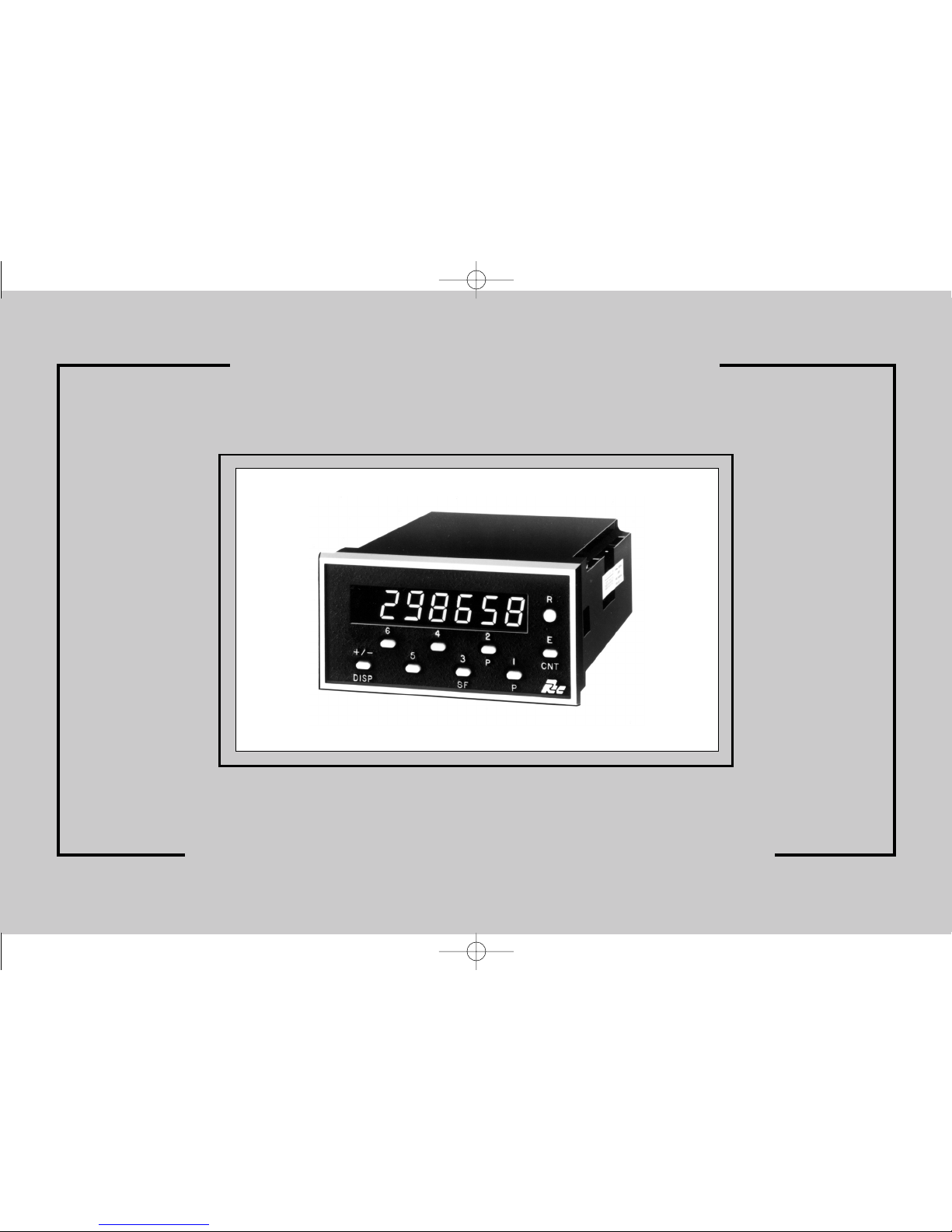
THE ASTRO LINE SERIES
GEMINI 1000/2000 INSTRUCTION MANUAL
GEM1&2CVR.QXD 4/10/02 11:04 AM Page 1
Page 2
INTRODUCTION
The Gemini 1000 and 2000 are both units in a multi-purpose series of
industrial control units that are field-programmable to solve multiple
applications. This series, known as the Astro-Line family of products, is built
around the concept that the end user has the capability to program different
personalities and functions into the unit in order to adapt to different indication
and control requirements.
The Gemini, which you have purchased, has the same high quality
workmanship and advanced technological capabilities that have made Red Lion
Controls the leader in today's industrial market.
Red Lion Controls has a complete line of industrial indication and control
equipment, and we look forward to being of service to you now and in the future.
CAUTION: Read complete instructions prior
to installation and operation of the unit.
CAUTION: Risk of electric shock.
GEM1&2CVR.QXD 4/10/02 11:04 AM Page 2
Page 3

I. GENERAL DESCRIPTION
Safety Summary................................................... 2
Programming The Gemini 1000/2000 ........................................ 2-3
Programming The Personality............................................ 3
Programming The Presets, Scale Factor, & Output Time Delays.......................... 3-4
Factory Settings ................................................... 5
Operator Accessible Functions With Programming Disabled ............................ 6
Diagnostics, Self-Test, & “Watchdog” Timer .................................... 6-7
Input Circuitry & Set-up ............................................... 7
Overflow Indication ................................................. 7
II. PROGRAMMING INSTRUCTIONS FOR THE COUNTER VERSION OF THE GEMINI 1000/2000........ 8-13
Codes 41, 43, 44, 45, & 46 ............................................. 8-9
Codes 51, 52, 53, 54, & 55 ............................................. 9-12
Codes 61, 66, Preset Values, & Scale Factor ................................... 12-13
Dual Preset Counting & Programming Application Example ............................ 14-15
III. PROGRAMMING INSTRUCTIONS FOR THE RATE INDICATOR VERSION OF THE GEMINI 1000/2000 . . . 16-21
Codes 41, 44, 45, & 46 ............................................... 16
Codes 51, 52, 53, 54, & 55 ............................................. 16-18
Codes 61, 63, 66, Preset Values, & Scale Factor.................................. 8-19
Dual Preset Rate Programming Application Example................................ 20-21
IV. 20 mA CURRENT LOOP SERIAL COMMUNICATIONS (GEMINI 2000 ONLY) ................. 22-29
Communication Format ............................................... 22
Sending Commands & Data To The Gemini 2000 ................................. 22-23
Receiving Data From The Gemini 2000....................................... 24
Print Options .................................................... 24
Current Loop Installation .............................................. 25-26
Communications Applications ............................................ 27-28
Troubleshooting Gemini Serial Communications .................................. 29
Serial Loop-Back Self-Test ............................................. 29
V. APPENDIX “A” - INSTALLATION & INPUT CONFIGURATION SWITCH SET-UP ............... 30-40
VI. APPENDIX “B” - SPECIFICATIONS & DIMENSIONS .............................. 41-42
VII. APPENDIX “C” - TROUBLESHOOTING GUIDE ................................ 43-45
VIII. APPENDIX “D” - FUNCTION COMMAND CODE SUMMARY ......................... 46-48
IX. APPENDIX “E” - SCALING FOR RATE INDICATION .............................. 49-50
X. APPENDIX “F” - GEMINI 1000/2000 PROGRAMMING CHARTS ........................ 51-54
XI. APPENDIX “G” - ORDERING INFORMATION .................................. 55
TABLE OF CONTENTS
Page 4

GENERAL DESCRIPTION
The Gemini is a two input, microprocessor-based device which offers the
features and performance ofa single (GEM 1000)/dual (GEM 2000) level preset
counter or sample time, rate indicator. The 6-digit display features 0.56" LEDs
with negative sign and overflow indicators. The internal precision is maintained
to 9 digits. The 20 mA Current Loop Option (Gemini 2000 only) makes possible
remote or computerized monitoring or control of the count, Presets and Scale
Factor.
Flexibility and usefulness are insured through user programmability. With
simple front panelkeystrokes and rear panel switch settings,any one of a number
of configurations can be selected. Once the selection is made, all or part of the
keyboard can be disabled to protect the settings and guarantee that no unwanted
changes can occur during the measurements. All set-up data is stored in
E
2
PROM, which will hold data for a minimum of 10 years without power.
Whenever the power comes on, the Gemini performs a series of internal
diagnostics to verifythe integrity of the storeddata. There is also aself-test mode
and an ever-present “watchdog” timer to prevent processor lockup.
The construction of the Gemini features a metal, die cast bezel for maximum
durability with high quality appearance. The sealed front panel meets NEMA
4/IP65 specifications for washdownand/ordust.Electrical connections are made
with removable, plug-in terminal strips at the rear of the unit. Clamp type
pressure plate terminals accept stripped #14 AWG wire without lugs.
As a counter, the Geminican monitor bi-directional, unidirectional (totalizer),
or quadrature signals. It can double or (with quadrature) even quadruple the
resolution of the incoming signal. Counting modes also provide for
anti-coincidence applications. Both channelsof count information are monitored
simultaneously, no counts are lost, and the final output can be chosen as the sum
or difference of the two input channels.
As a rate indicator, a variety of sampling times are available. Accurate to one
hundredth of a percent, the sampling time can be set as 1, 2, 5, 10, 20, or 50 seconds.
The preset level(s) can be selected to control an open collector output(s). The
optional Gemini plug-in relay board makes it easy to field upgrade your Gemini
to provide 5amp, 240 VAC relay output(s). Theoutput(s)arealso programmable
and can be set for terminate at the “other” output start, “other” output end, at
reset or reset end, after time delay, or boundary.
Preset and reset behavior of the output(s) and display are completely
programmable. The preset(s) can have a value ranging from -999999 to +999999.
Decimal placement will be the same as the decimal placement on the input value.
Various resetmodes can beselected: manual resetto zero or preset; automatic
reset to zero or preset; or automatic reset after time delay. The manual reset will
always override automatic reset, if it has been enabled.
The scale factor, moveable decimal point, dummy right hand zeros, leading
zero blanking, and decade divider capabilities of the Gemini permit complete
control of the Gemini display. These features provide easy conversion of input
signals to desired measurement units (feet to meters, etc.). The input values can
be multiplied by any number from -5.9999 to +5.9999 with the scale factor. The
addition of up to 3 dummy right hand zeroes gives an effective display
multiplication of 10, 100, or 1000. Similarly, the decade divider provides 1, 2, or
3 decades of prescaling.
SAFETY SUMMARY
All safety related regulations, local codes and instructions that appear in the
manual or on equipment must be observed to ensure personal safety and to
prevent damage to either the instrument or equipment connected to it. If
equipment is used in a manner not specified by the manufacturer, the protection
provided by the equipment may be impaired.
Do notuse this unit to directlycommand motors, valves, or otheractuators not
equipped with safeguards. To do so, can be potentially harmful to persons or
equipment in the event of a fault to the unit.
PROGRAMMING THE GEMINI
When your Gemini arrives from the factory, it has already been programmed
to function as a preset counter.
The personality,functions, and modesare then setby pressing theappropriate
keys asindicated by the embossed numbersabove them. A functionis defined by
a two-digit code which appears on the left side of the display. The mode of that
function is shown as a one-digit code on the right side of the display. At times
there will be a (-) sign modifier.
Page 5
Data forthe presets, scale factor, and time delaysare entered differently. Each
digit key controls the digit on the display directly above it. Changing the digits
can bedone by repeatedlypressing the key beneath the digit positionyou wish to
change orby merely holding it down.As you hold itdown or press it, thevalue of
that digit will change cyclically, counting up to 9, then to 0, and then up again.
The 6 numbered keys correspond to the six digits, and the “+/-” key
correspond to polarity.
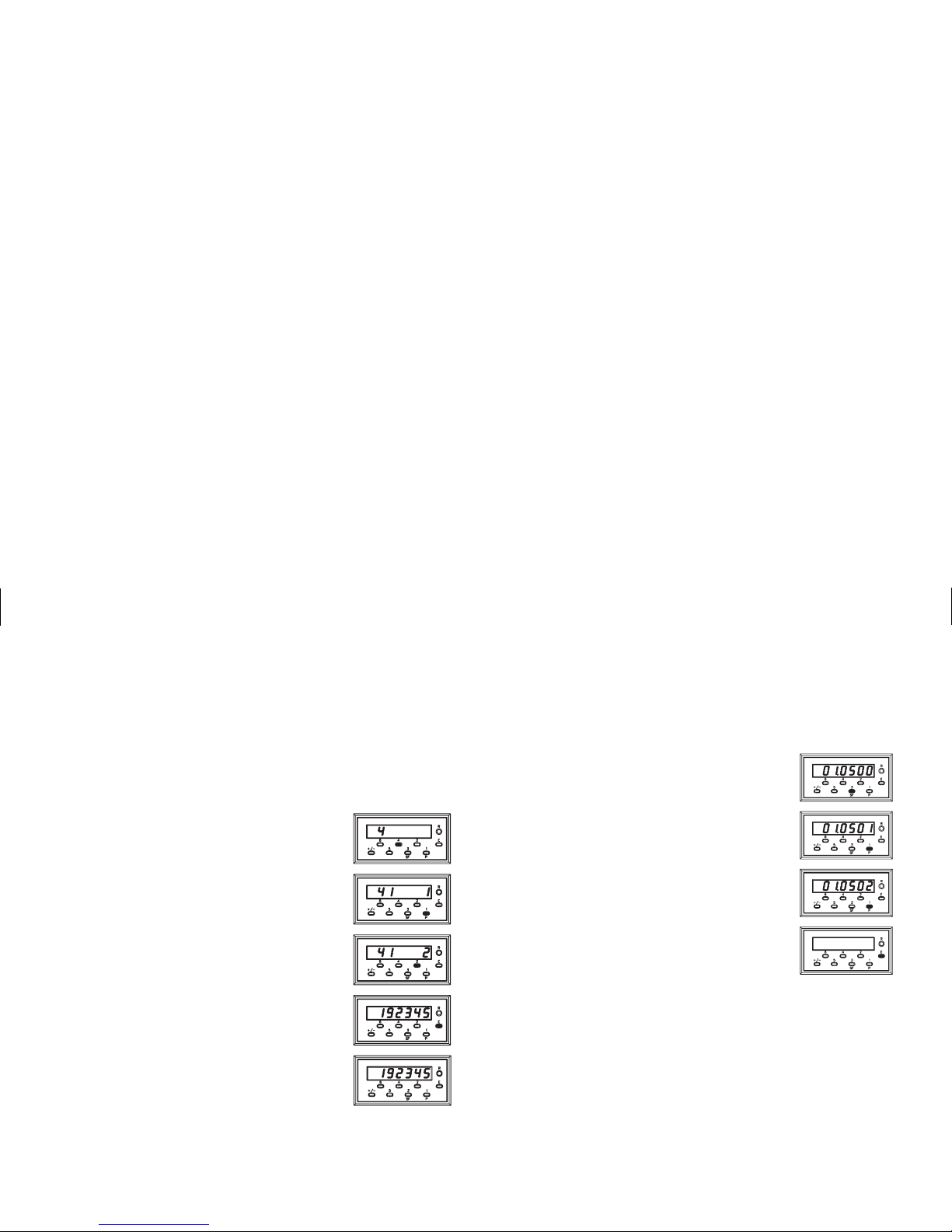
PROGRAMMING THE PERSONALITY
Entering function and mode is easily accomplished by
pressing the appropriate digit key as indicated by the
embossed number above it. For the personality function,
enter 41 by pressing the front panel key 4.
Then press the front panel key 1. The leftmost LEDs
show the function; the rightmost is the present mode.
A new mode selection is made by entering a new
number. On some of the entries, you have the option of a
plus (+) or minus (-) sign. In the cases where a “+” sign is
required, no sign will be displayed. If you do enter a “-”
sign (using the “+/-” key), a minus sign will be displayed
in front of the appropriate digit.
Pressing the “E” key finalizes the change. The display
will now show the count or rate value immediately.
If you do not press the “E” key the change will not be
recorded. The display will remain for 15 seconds, and then
return to normaloperatingmode using the old functionand
mode settings. (Note: The reset button “R”, if enabled, is
always active. Pressing reset will immediately abort the
function selection, and reset the instrument.)
The majorpersonality is functioncode 41. If it is changed from rate to counter
or vice-versa, it may effect settings like count mode, reset mode, and output
termination modes.
PROGRAMMING THE PRESETS, SCALE FACTOR, &
OUTPUT TIME DELAYS
The scale factor and preset values are commonly reprogrammed on a daily
basis. As such, single keystroke access has been provided on the front panel.
To change the scale factor, press the “SF” (3) key. The
display will then show you’re the present scale factor value.
The scale factor can be set from -5.9999 to +5.9999.
Changing the digits can be done by repeatedly pressing
the key beneath the digit position you wish to change or by
merely holding it down.
The new value will be entered when the “E” key is
pressed. This key must be held down until the display has
blanked after whichtheunit will return to the normaldisplay
mode.
The internal countvalue is multiplied bythescale factor value, whichchanges
the displayed value accordingly. This is true for all response modes, Count with
Inhibit, Count with UP/DN Control, Two Input Anti-Coincidence and for all
Quadrature Counting Modes.
It is important to note that the precision of an application cannot be improved
by using a scale factor greater than one. To accomplish greater precision, more
pulse information mustbe generated per measuring unit.For example, if 5 pulses
are being received per foot of material, the precision of 10th of feet cannot be
attained by simply programming a 2.00 scale factor, even though the display is
reading in tenths. In this case, the display will increment by two for each count
input. Thus,if an oddpreset value is entered, such as 6.7 ft., the Geminiwill alter
the preset display to read in even tenths of feet.
Page 6

PROGRAMMING THE PRESETS, SCALE FACTOR, &
OUTPUT TIME DELAYS (Cont’d)
The preset level is changed in the same way as the scale
factor. Pressing the “P” (1) key will display the present
value of preset 1.
To change the value, merely cycle the digits through as
you have done before. The presets can be selected from
-999999 to +999999.
The new value will be entered when the “E” key is
pressed. (The display will blank for a short duration of time
and then re-display the count value.)
The Scale Factor value will have a direct effect on the
preset being entered. For scale factors greater than one, the
preset shouldbe an integermultiple of the scale factor. If it is
not, the Gemini will automatically adjust the preset value up
or down to force it to be evenly divisible by the scale factor.
A time delay is changed by entering a two-digit function
code. The display will then immediately show the present
time delay in seconds with a two decimal place accuracy.
The time delay values can be set from .01 to 599.99 seconds.
To change output1 time delay, enter function code53and
enter the new value by holding down or repeatedly pressing
the key below the digit position you wish to change.
The new value will be entered when the “E” key is pressed
and the display will immediately return to the count value.
Note: A time delay value of zero cannot be programmed into the Gemini. If a
value of 0 is entered into the display and the “E” key is pressed, the unit will
continue to use the previous time delay value.
As with the otherfunctions, you must press “E” to record the changes. For the
data entry modes, if you do not press the “E” key, a time out of 5 seconds occurs,
then the display returns to operating mode without any change to the value. The
only time any change will occur is when the “E” key is pressed. As in all other
modes, the reset button is always active if enabled. Pressing “R” will abort the
data entry and reset the instrument.
Page 7

FACTORY SETTINGS
Keys Struck Display Description
4,1 41 1
Personality selected as Counter
4,3 43 1
Count with Inhibit
4,4 44 1
Count on one edge of input (no doubling)
4,5 45 1
Scale Multiplier of 1.0
4,6 46 1
Leading zero blanking and no decimal point
5,1 51 1
Manual reset-to-zero, aslong as buttonremainsPUSHED
5,2 52 3
Output 1 terminates at Reset, Normal Output Phase
5,3 0000.10
0.10 second Output 1 time delay. Note that this function
will display the actual amount of time delay, and not a
mode command. In this case, it displays a 0.10 indicating
0.10 seconds.
*5,4 54 3
Output 2 terminates at Reset, Normal Output Phase.
*5,5 0000.10
0.10 second Output 2 time delay. Note that this function
will display the actual amount of time delay, and not a
mode command. In this case, it displays a 0.10 indicating
0.10 seconds.
6,1 61 4
No right-hand dummy zeros
6,6 66 4
Reset enabled along with scale factor and presets.
SF(3) 01.0000
Scale Factor set to unity
P(1) 000500
Preset 1 value equals 500
*P(2) 001000
Preset 2 value equals 1000
When the unit is shipped from the factory, the functions and modes are
programmed as shown above.
*Applies to the Gemini 2000 only.
Page 8

OPERATOR ACCESSIBLE FUNCTIONS WITH
PROGRAMMING DISABLED
(For details on keyboard entry, see preceding section)
One of the important features of the Gemini is the ability to disable
programming. With this ability, accidental bumping of the keys or tampering by
unauthorized personnel canbe prevented. However, itmaybe necessary to allow
reset and certain programming functions, such as, preset and scale factor values
to be changed in daily operation. The Gemini, through the use of the “Operator
Accessible Functions”Modes, can enable thesefunctions even when the “PGM.
DIS.” terminal is connected to “COMMON”.
The “Operator Accessible Functions” Modes are programmed by a two-digit
function code (66), like the other function modes. But in this case, the modes do
not take effect until the “PGM. DIS.” terminal is connected to “COMMON”.
(Bear in mind that all function modes of the Gemini are accessible until “PGM.
DIS.” is connected to “COMMON”.)
There are four basic “Operator Accessible Functions” Modes available.
These modes enable the following functions.
1. NO FUNCTIONS EXCEPT RESET ENABLED - In this mode, manual
reset is enabled, but none of the programming functions can be changed.
However, the functions can be interrogated.
2. PRESET PROGRAMMING AND RESETENABLED- The entire front
panel is disabled with the exceptions of preset programmability and
manual reset. All functions can be interrogated.
3. SCALE FACTOR PROGRAMMING AND RESET ENABLED - The
entire front panel is disabled with the exceptions of scale factor
programmability and manual reset. All functions can be interrogated.
4. SCALE FACTOR AND PRESET PROGRAMMING, AND RESET
ENABLED - The entirefrontpanel is disabled with the exceptionsofscale
factor and preset programmability, and manual reset. All functions can be
interrogated.
All of these four basic modes can be modified with the addition of a minus
sign. The minus sign disables the manual reset, at the front panel and the remote
reset terminal, at the rear of the unit.
There is also a rear panel DIP switch which permits disabling of the front panel
manual resetbutton. This is independentofthe rear terminal remotereset,and can be
used in conjunction with any front panel disable mode. The combination of manual
and remote inputs provides a high level of security without sacrificing flexibility.
DIAGNOSTICS, SELF TEST, & “WATCHDOG” TIMER
The security and integrity of the Gemini is further enhanced by its self-test,
diagnostic and “watchdog” timer capabilities.
The diagnostics are concerned with the special, no power memory of the
Gemini. Whenever the power is turned off, on purpose or by accident, all pertinent
function settings and measurements are automatically saved.Then, when poweris
restored, the function and data are re-instated. This allows you to program a
Gemini once and not have to re-program it until you wish to use it in another mode.
When the function codes and data are saved, computations are made with
these values.The result of thesecomputations is stored in the memory to serve as
a check against possible error. Then on power up, the same computations are
repeated on thestored data. If theresults do not agree withthe stored results, then
a “P” will appear on the left side of the display. If this occurs, refer to the
troubleshooting guide for directions.
Another error indicator is the “watchdog” timer. In order to insure proper
software functioning, the program constantly monitors itself. If the proper sequence
and timingofinternalevents does not occur, an“E”willappear on the left sideofthe
display. If this occurs, refer to the troubleshooting guide for instructions.
The final type of built-in error checking is the front panel initiated self test. It
can be performed at any time, even when the Gemini is running. It will not
interfere with the accumulation ofcounts or control functions. A function code of
“6” “+/-” starts the test. At this time, whatever wasdisplayed will be replaced by
a string ofdecimal points and the overflowindicator. Then, the display willshow
a string of 9’s, then 8’s then 7’s, etc., until a string of 0’s is shown. The self test
will then turn off the overflow indicator and activate the minus(-) sign. After this,
the unit showsaninterlace pattern of -0, 1, 0,1,0, 1, then -2, 1, 2,1,2, 1, followed
by -2, 3, 2, 3, 2, 3, etc., until -8, 9, 8, 9, 8, 9, is reached. At this time, the outputs
can be tested by pressing the “P” (1) and “P” (2) keys.
(The program disable pin must be high in order to allow activation of the
output.)
Note: During selftest caution should be used whentestingthe outputs so as not to
cause any undesirable or hazardous conditions in the system.
Page 9

An automatic exit will take place after six seconds or immediately if the
Program Disable terminal is connected to common. Normal length of display
time for each of the patterns is approximately 0.5 seconds. Rapidly pressing the
“+/-” key during self test can speed up the process.
INPUT CIRCUITRY & SET-UP
There are two independent input channels on the Gemini. Various types of
sensor outputs can be accommodated by appropriate DIP switch set-up; such as
TTL or CMOS logic, current sinking, current sourcing, or dry contact.
Channel A consists of a logic input and a separate low level magnetic pickup
input.
Channel B is a completely independent count or control input channel. Like
Channel A, it can be programmed with DIP switches for a wide variety of logic
inputs and is identical to Channel A in this regard.
For a complete detailed description of set-up, see Appendix “A”.
OVERFLOW INDICATION
The Gemini features an overflow indicator (LED) which is located to the left
of the sixth digit and above thepolarity annunciator. This LED will turn on if the
capacity of the display (6-digits) is exceeded or if the internal count capacity
(9-digits) is exceeded. Use of extremely small scale multiplier and scale factor
values can cause the internal count capacity to overflow before the displayed
value wouldoverflow. It should also benoted that the useof Right Hand Dummy
Zeros or Scale Factors larger than one could cause the Displayed value to
overflow before a value of 999,999 (6-digits) is accumulated.
When the capacity of the display is exceeded, the count value will be
maintained and willbe valid. But if theinternalcount value is exceeded, thenthis
value may no longer be valid.
Page 10

PROGRAMMING INSTRUCTIONS FOR THE COUNTER VERSION OF THE GEMINI
The first part of this section provides detailed description of the function
command codes for counting modes, reset modes, output terminations, etc. Then,
using an actual application example, the programming instructions for a counter
version will be “walked through”, to give the user a full understanding of the
Gemini programming procedure. The descriptions below give the function
command code first, followed by the individual mode identifier. The Function
Command Code Summary in the appendix lists all codes. (Only commands and
modes pertaining to the counter will be discussed in this section.)
CODE 41 - UNIT PERSONALITY
Two basic personalities are available for the Gemini. They are the counter
mode and the rate indicator mode.
[41 1] COUNTER-Setting this mode selects the unit to functionasa counter.
This is the basic personality mode and must be programmed before any
other modes areset. (This command forces defaultmode values in certain
command codes.)
CODE 43 - INPUTSA&BRESPONSE MODES
The Gemini has six different input response modes. They are: Count with
Inhibit; Count with Up/Down Control; Two-Input Anti-Coincidence Add;
Two-Input Anti-Coincidence Add/Subtract; Quadrature; and Quadrature X4.
[43 1] COUNT WITH INHIBIT - Input A in this case, serves as the count
input. Input B serves as the inhibit terminal. When Input B is low, count
signals appearing at A will be ignored. When Input B is at a high level,
negative going (falling) signals appearing at A will be counted.
[43 2] COUNT WITH UP/DOWN CONTROL - When in this mode, count
direction can be controlled by a second input. Input A serves as the count
input, and Input B serves as the direction control signal. When B is at a
high level, negative going transitions at A will cause the unit to count in
the positive direction. When Input B is at a low level, negative going
transitions at A will cause the counter to count in the negative direction.
[43 3] TWO(2)INPUTANTI-COINCIDENCEADD/SUBTRACT-Thismode
effectively separates count pulses which may simultaneously appear at the
two inputs. The Gemini unit then processes the count pulses into a string of
time-separated pulses, so the internal counter will not lose any counts. Input
A serves as the add input, and Input B serves as the subtract input.
[43 4] TWO (2) INPUT ANTI-COINCIDENCE ADD - This mode functions
in the same manner as the Two Input Add/Subtract mode except both
Input A and Input B serve as “ADD” inputs.
[43 5] QUADRATURE COUNTING - Quadrature counting modes are
primarily used in positioning and anti-jitter applications. The reason this
mode is used is due to the manner in which two pickups are positioned
relative to each other.Input B is a pulse trainsignal shifted 90
o
away from
Input A. These two signals are processed by the Gemini as follows:
Input A serves as the count input, while Input B serves as the quadrature
input (B is the inputshifted 90
o
away from A). For quadraturewith single edge
counting, the counter will count in a positive direction when Input A is a
negative going edge and Input B is at a low level. The counter will count in a
negative direction when Input A is a positive going edge and Input B is at a
low level. All transitions on Input A are ignored when B is at a high level.
These logic rules providethe basis for anti-jitter operation which willprevent
false counts from occurring due to back-lash, vibration, chatter, etc.
When two edge counting is used, the quadrature mode works the same as
with single edge counting when Input B is low. But when Input B is at a high
level, counts atInput A are no longerignored.Insteadthe logic rules for A are
complemented, allowing both edges of A to be counted. This doubles the
effective resolution of the encoded input.
[43 6] QUADRATURE TIMES4 - This modetakes the quadrature mode, with
two edge counting, one step further. In quadrature times4, both Input A and
Input B serve as count or quadrature input, depending on their state.In one
instance, Input A will serve as the count input and Input B will serve as the
quadrature input. In another instance, Input A will be the quadrature input
and Input B will be the count input. This enables each edge, positive and
negative going, of each input, A and B, to be counted. This results in a
resolution four times greater than in the ordinary quadrature mode.
Page 11

CODE 44 - NUMBER OF COUNT EDGES
The Gemini can be programmed for either single edge or two edge (doubling)
counting. The number of count edges cannot be set when the count mode is
programmed for quadrature X4 operation (the Gemini will ignore any attempt to
enter function command code 44 when set for quadrature X4).
[44 1] SINGLE EDGE COUNTING - The unit counts on the negative going
(falling) edge of the count input signal. The count mode descriptions
describe how each mode uses this method of edge counting.
[44 2] TWO EDGE COUNTING - This mode is used when doubling of the
count signal input is required. The unit counts on the positive going
(rising) edge of the count input signal, as well as, the negative going
(falling) edge.
CODE 45 - SCALE MULTIPLIER
There arefour scale multiplier values thatare available. They are:1; 0.1; 0.01;
and 0.001. They effectively divide the internal count value by 1, 10, 100, and
1000 respectively, to yield the displayed count value. Note: Use of a small scale
multiplier inconjunction with a smallscale factor could cause the internal count
value to be exceeded before the 6-digit display value is exceeded. See “Overflow
Indication” section for more details.
[45 1] SCALE MULTIPLIER VALUE OF 1 - This value multiplies the
internal count by 1.
[45 2] SCALE MULTIPLIER VALUE OF 0.1 - This value multiplies the
internal count by 0.1. (Effectively divides by 10.)
[45 3] SCALE MULTIPLIER VALUE OF 0.01 - This value multiplies the
internal count by 0.01. (Effectively divides by 100.)
[45 4] SCALE MULTIPLIER VALUE OF 0.001 - This value multiplies the
internal count by 0.001. (Effectively divides by 1000.)
CODE 46 - DECIMAL POINT & LEADING ZERO BLANKING
There are six basic modes of decimal point placement on the Gemini. The
decimal point is placed to the right of the display digit that corresponds to the
mode identifier.(The right most decimal point,digit 1, is never turnedon.) A “-”
sign in front of the mode identifier will inhibit leading zero blanking. The
absence of the “-” sign will enable leading zero blanking.
[46 1] 0
[46 2] 0.0
[46 3] 0.0 0
[46 4] 0.000
[46 5] 0.0000
[46 6] 0.00000
[46 -1] 000000
[46 -2] 00000.0
[46 -3] 0000.00
[46 -4] 000.000
[46 -5] 00.0000
[46 -6] 0.00000
CODE 51 - RESET MODES
The Gemini has six different reset modes. They are: Manual Reset to Zero;
Manual Reset to Preset; Automatic Reset to Zero After Output Time Delay;
Automatic Reset to Preset after Output Time Delay; Automatic Reset to Zero at
the Beginning of the Output Time Delay; and Automatic Reset to Preset at the
Beginning of theOutputTime Delay. (Note: For theGemini2000, reset to preset
modes reset to preset 2 and Output refers to Output 2.) There are also two
methods by which manual reset can act on the unit (reset must be enabled). The
first is a “maintained” reset action where the unit is held at reset as long as the
reset terminal is held low or the front panelreset button is pressed. The second is a
“momentary” reset in which the unit resets when reset is activated and
immediately starts counting eventhoughtheterminal may still be low or the reset
button may still be pressed. (Note: In momentary reset, the display will not
update until reset is released, but internal counting and all other functions are
operative.) A “-” sign in front of the code identifier will provide for
“momentary” reset, and the absence of a “-” sign will give “maintained” reset.
[51 1] MANUAL RESET TO ZERO (RTZ) - Manual reset to zero is
accomplished by pullingremote reset to ground, orif the front panel reset
is enabled, by pressing the front panel reset button. Reset is “maintained”.
[51 2] MANUAL RESET TO PRESET (RTP) - Manual reset to preset is
accomplished by pulling reset to ground, or if the front panel reset is
enabled, by pressing the front panel reset button. Reset is “maintained”.
LEADING ZERO
BLANKING
LEADING ZERO
BLANKING INHIBITED
Page 12

CODE 51 - RESET MODES (Cont’d)
[51 3] AUTOMATIC RESET TO ZERO AFTER OUTPUT TIME DELAY -
The counter resets to zero when the output time delay ends. Manual reset
is “maintained” and will override automatic reset.
[51 4] AUTOMATICRESET TO PRESET AFTER OUTPUTTIME DELAY -
The counter resets to the preset value when the output time delay ends.
Manual reset is “maintained” and will override automatic reset.
[51 5] AUTOMATIC RESET TO ZERO AT THE BEGINNING OF THE
OUTPUT TIME DELAY - When in this reset mode, the unit will
automatically reset to zero at the beginning of the output time delay(when
the preset point is reached). Forthe Gemini 2000, the output 1 and output 2
time delays must be shorter than the time required for the counter to count
to the preset 2 value. Otherwise, the output(s) will appear to be latched on.
Manual reset is “maintained” and will override automatic reset.
[51 6] AUTOMATIC RESET TO PRESET AT THE BEGINNING OF THE
OUTPUT TIME DELAY - In this reset mode, the unit will automatically
reset to preset at the beginning of the output time delay (when zero is
reached). For the Gemini 2000, theoutput 1 and output 2 time delay must
be shorter than the time required for the counter to count to zero.
Otherwise, the outputs will appear to be latched on. Manual reset is
“maintained” and will override automatic reset.
[51 -1]
[51 -2]
[51 -3] These modes are the same as above with the exception
[51 -4] that Reset is set for “momentary” operation.
[51 -5]
[51 -6]
CODE 52 - OUTPUT 1 TERMINATION MODES
The Gemini has six Output Termination Modes. They are: Terminate at
Output 2 Start; Terminate at Output 2 End; Terminate at Manual Reset;
Terminate at Manual Reset End; Terminate After Time Delay; and Boundary.
A Reverse Phase Option is available on the Gemini. This refers to
complementing the logic state of the output. With normal phase operation, when
the count reaches preset 1 the output will turn on. The reset condition of the
output is output off. In reverse phase operation, the output turns off when the
preset is reached. The reset condition of the output is output on. (Note: The state
of the relay, if used, is also reversed.) A “-” sign in front of the mode identifier
will provide for reverse phase operation. The absence of a “-” sign will give
normal phase operation.
In all modes except boundary, when the unit is powered up, the relays or
outputs will beturned off. This is done tohelpprevent a hazardous situation from
occurring. If other than boundary or time delay operation is selected, the unit
should be reset upon power up.
[52 1] TERMINATE AT OUTPUT 2 START - Output 1 will terminate when
Output 2 starts. (Gemini 2000 only)
[52 2] TERMINATE AT OUTPUT 2 END - Output 1 will terminate when
Output 2 terminates. (Gemini 2000 only)
[52 3] TERMINATE AT MANUAL RESET - In this mode, output 1, once
activated, does notdeactivateuntil the moment a reset occurs.Thereset can be
from the front panel button or from the remote reset terminal at the rear of the
unit. The output is set for normal phase operation.
[52 4] TERMINATE AT MANUAL RESET END - This mode is like the
preceding output mode, except output 1 deactivates when the reset ends. The
output is set for normal phase operation.
[52 5] TERMINATE AFTER OUTPUT 1 TIME DELAY - Once output 1 has
been activated, it will deactivate after the predetermined length of output 1
time delay has expired. Manual reset, by either the front panel button or the
reset terminal, will override the output 1 time delay and reset the output. The
output is set for normal phase operation.
[52 6] BOUNDARY MODE - This mode can be used when the unit is
functioning as a counter, but is more applicable to the rate indicator mode.
When in boundary mode, the preset 1 value serves as the boundary point.
When the count is less than the preset, the output is not activated (normal
phase). When the count is greater than or equal to the preset, the output is
activated. Ifthe count value were todrop below preset, theoutput would again
deactivate. For negative preset points, the output is not activated when the
count value is more positive than the preset value. When the count is more
negative than or equal to the preset, the output is activated. If the count
becomes more positive than the preset, the output again deactivates. Upon
power up, the output will “remember” its power down boundary condition
and go to that state. The output is set for normal phase operation.
Page 13

[52 -1]
[52 -2]
[52 -3] These modes are the same as above with the exception
[52 -4] that the output is set for reverse phase operation.
[52 -5]
[52 -6]
CODE 53 - OUTPUT 1 TIME DELAY
The Gemini has the capabilityof varying the output time delay from 0.01 second
to 599.99 seconds. When the code is entered, instead of a single mode identifier
digit beingdisplayed, six digitswill be shown. Refer to the “ProgrammingPreset,
Scale Factor, and Output Time Delay” section for more details about entering.
Output time delay will be terminated if the unit is manually reset.
Note: A time delay value of zero cannot be programmed into the Gemini. If a
value of 0 is entered into the display and the “E” key is pressed, the unit will not
enter the 0, but will revert back to displaying the previous time delay.
CODE 54 - OUTPUT 2 TERMINATION MODES (GEMINI 2000
Only)
The Gemini 2000 has six Output2 Termination Modes. They are: Terminate at
Output 1 Start; Terminate at Output 1 End; Terminate at Manual Reset;
Terminate at Manual Reset End; Terminate After Time Delay; and Boundary.
A Reverse Phase Option is available on the Gemini 2000. This refers to
complementing the logic state of the output. With normal phaseoperation, when the
count reaches preset 2, output 2 will turn on. The reset condition of the output is
output off.In reverse phaseoperation,theoutput turns off when the presetis reached.
The reset condition ofthe output is output on.(Note: The state of the relay, if used,is
also reversed.) A “-” sign in front of the mode identifier will provide for reverse
phase operation. The absence of a “-” sign will give normal phase operation.
In all modes except boundary, when the unit is powered up, the relays or
outputs will beturned off. This is done tohelpprevent a hazardous situation from
occurring. If other than boundary or time delay operation is selected, the unit
should be reset upon power up.
[54 1] TERMINATE AT OUTPUT 1 START - Output 2 will terminate when
Output 1 starts.
[54 2] TERMINATE AT OUTPUT 1 END - Output 2 will terminate when
Output 1 terminates.
[54 3] TERMINATE AT MANUAL RESET - In this mode, output 2, once
activated, does notdeactivateuntil the moment a reset occurs.Thereset can be
from the front panel button or fromthe remote reset terminal, at the rear ofthe
unit. The output is set for normal phase operation.
[54 4] TERMINATE AT MANUAL RESET END - This mode is like the
preceding output mode, except output 2 deactivates when the reset ends. The
output is set for normal phase operation.
[54 5] TERMINATE AFTER OUTPUT 2 TIME DELAY - Once output 2 has
been activated, it will deactivate after the predetermined length of output 2
time delay has expired. Manual reset, by either the front panel button or the
reset terminal, will override the output 2 time delay and reset the output. The
output is set for normal phase operation.
[54 6] BOUNDARY MODE - This mode can be used when the unit is
functioning as a counter, but is more applicable to the rate indicator mode.
When in boundary mode, the preset 2 value serves as the boundary point.
When the count is less than the preset, the output is not activated (normal
phase). When the count is greater than or equal to the preset, the output is
activated. Ifthe count value were todrop below preset, theoutput would again
deactivate. For negative preset points, the output is not activated when the
count value is more positive than the preset value. When the count is more
negative than or equal to the preset, the output is activated. If the count
becomes more positive than the preset, the output again deactivates. Upon
power up, the output will “remember” its power down boundary condition
and go to that state. The output is set for normal phase operation.
[54 -1]
[54 -2]
[54 -3] These modes are the same as above with the exception
[54 -4] that the output is set for reverse phase operation.
[54 -5]
[54 -6]
Page 14

CODE 55 - OUTPUT 2 TIME DELAY (GEMINI 2000 Only)
The Gemini 2000 has the capability of varying the output time delay from 0.01
second to 599.99 seconds. When the code is entered, instead of a single mode
identifier digitbeing displayed, six digitswillbe shown. Refer tothe “Programming
Preset, Scale Factor, and Output Time Delay” section for more details about
entering. Output time delay will be terminated if the unit is manually reset.
Note: A time delay value of zero cannot be programmed into the Gemini 2000. If a
value of 0 is entered into the display and the “E” key is pressed, the unit will
not enter the 0, but will revert back to displaying the previous time delay.
CODE 61 - RIGHT HAND DUMMY ZEROS
These zerosare used toeffectively move significantdigits to theleft. Up tothree
non-functional zeros can beused. Therefore, a normal count of 1 couldbe shown as
a 10, 100, or 1000 without setting or changing any other parameter of the system.
Note: Use of dummyzeros or scale factor values greater than onecould cause the
displayed value to overflow before a value of 999,999 (6-digits) is
accumulated. See “Overflow Indication” section for more details.
[61 1] 1 RIGHT HAND DUMMY ZERO - One is displayed.
[61 2] 2 RIGHT HAND DUMMY ZEROS - Two are displayed.
[61 3] 3 RIGHT HAND DUMMY ZEROS - Three are displayed.
[61 4] NO RIGHT HAND DUMMY ZEROS - None are displayed.
CODE 66 - “OPERATOR ACCESSIBLE FUNCTIONS” MODES
(PGM. DIS. Connected to “COMMON”)
The Gemini has four basic levels of “Operator Accessible Functions”.
However, each of these levels can be modified to enable or disable manual reset.
When the “PGM. DIS.” (program disable) terminal is connected to
“COMMON”, access to all functions is disabled except for those listed below
which will remain enabled. All of the function codes and parameters can be
interrogated regardless of the “Operator Accessible Functions” mode selected.
A “-”sign in front of the modeidentifierwilldisable reset and the absence of a
“-” sign will enable the reset terminal and front panel reset button.
(Note: Front panel reset can be independently “Disabled” by using the disable
reset DIP switch.)
[66 1] NO FUNCTIONSENABLED EXCEPT RESET - In this mode, manual
reset is enabled, but none of the programming functions can be changed.
[66 2] PRESET PROGRAMMING AND RESET ENABLED - In this mode,
manual reset and the programming of the Preset Values are enabled.
[66 3] SCALE FACTOR PROGRAMMING AND RESET ENABLED - In this
mode, manual reset and the programming of the Preset values are enabled.
[66 4] SCALE FACTOR, PRESET PROGRAMMING AND RESET
ENABLED - In this mode, manual reset and the programming of the Scale
Factor and Preset Values are enabled.
[66 -1]
[66 -2] These Modes are the same as above with the
[66 -3] exception that manual reset is disabled.
[66 -4]
PRESET VALUES
Whenever the count value equals the preset value, an output action will occur.
(This action depends on the previously programmed modes). The Preset Value may
vary from -999,999 to 999,999.Refer to “ProgrammingThe Presets, ScaleFactors,
And Timed Output Values” section for instructions on entering the Preset Value.
The Scale Factor value will havea direct effect on the preset being entered. For
Scale Factors greater than one, the preset value should be an integer multiple of
the scale factor. If it is not, the Gemini will automatically adjust the preset value
up or down to force it to be evenly divisible by the scale factor.
“P”(1) - PRESET 1 VALUE
“P”(2) - PRESET 2 VALUE (GEMINI 2000 ONLY)
SCALE FACTOR
“SF”(3) SCALE FACTOR- The internal count valueis multiplied by the scale
factor value, which changes the displayed value accordingly. This is true for all
response modes, Count with Inhibit, Count with UP/DN Control, Two Input
Anti-Coincidence and for all Quadrature Counting Modes. Scale factor is used
primarily for conversion fromexisting pulses per unit of measure to the required
displayed units. This includes conversion from different units of measure (i.e.
feet to meters, etc.). The scale factor value may range from -5.9999 to 5.9999.
(Refer to “Programming The Presets, Scale Factor & Output Time Delays”
section for entering instructions.)
Page 15

It is important to note that the precision of an application cannot be improved
by using a scale factor greater than one. To accomplish greater precision, more
pulse information mustbe generated per measuring unit.For example, if 5 pulses
are being received per foot of material, the precision of 10th of feet cannot be
attained by simply programming a 2.000 scale factor, even though the display is
reading in tenths. In this case, the display will increment by two for each count
input. Thus, if an odd preset value was entered, such as 6.7 ft., the Gemini will
alter the preset to read in even tenths of feet.
Note: Use of a small scale factor in conjunction with a small scale multiplier
could cause the internal count value to be exceeded before the 6-digit display
value is exceeded. See “Overflow Indication” section for more details.
Page 16
DUAL PRESET COUNTING & PROGRAMMING APPLICATION EXAMPLE
A typical industrial applicationfor Gemini 2000 will require both aslowdown
output and a final stop output. The Gemini can easily beprogrammed to solve this
requirement. For instance, let’s look at a textile web process that requires a dual
output asthe web progresses to the proper length. A typicallength of material for
this application is 10,000 feet for total length, and a slow down output 500 feet
prior to the end of the 10,000 foot length. In this case, it would be best to set the
unit up as Manual Reset to Preset 2. Preset 2 would be set at 10,000, and Preset 1
would be set for 500. The counter would count down to 500, and output 1 would
activate and cause the process to slow down until 0 is reached at which point
Output 2 would activate and latch for final stop. The advantage of using manual
Reset to Preset 2 is that when changing the total length it is only necessary to
change Preset2 (length). Preset 1 (slow down) wouldremain the same, assuming
the same amount of slow down is required.
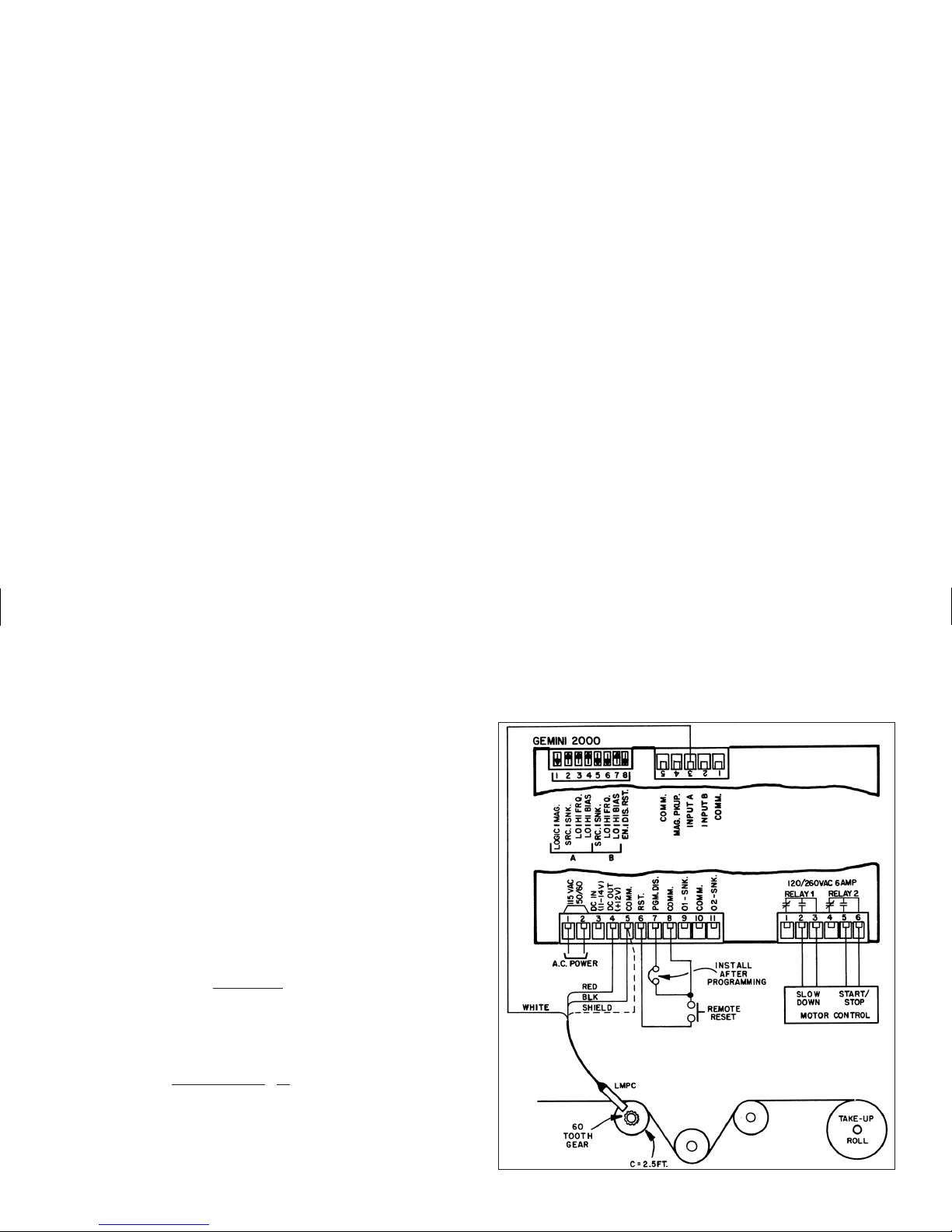
The accompanying drawing shows an LMPC sensing a 60 tooth gear which is
attached to a 2.5 ft. circumference drum. Since the unit of measure is a foot, the
first step is to find the number of pulses per foot that will be used. The following
formula is used.
Pulses/ft.
=
60 pulses/rev.=24 pulses/ft.
2.5 ft./rev.
Since the desired readout is in feet, and there are 24 pulses per foot, it is
necessary to scale the count. To determine the multiplier that is needed, the
formula below is used.
K=
“desired reading”=1=0.0416667
“# of pulses” 24
To get the maximum amount of decimal point accuracy a scale multiplier of
0.01 (divide by 100) is used which would give us a scale factor (rounded off) of
4.1667. If weused the multiplier as thescale factor, and used ascale multiplier of
1, the scale factor would round off to 0.0417, in which case 2 decimal places of
accuracy would be lost.
Page 17

HARDWARE SET-UP
The application drawing shows how the hardware for this system is to be
connected. The Red, Black, and White wires of the LMPC are connected to the
DC OUT, COMM., and INPUT A terminals respectively. The shield of the
LMPC cable is also connected to COMM. A Remote reset button is connected
between the RST.and COMM. terminals. After the programmingiscompleted,a
jumper is connected between PGM. DIS. and COMM. terminals of the Gemini
2000. This terminal, in conjunction with the “Operator Accessible Functions”
mode, will prevent accidental changes in the units operating modes. The
Normally Open contact of Relay 1 is connected to the slow down actuator, and
the Normally Open contact of Relay 2 is connected to the motor control.
DIP switch1is set to theLOGIC position. This allows InputA to function as the
count input. Switch position 2 is set to SNK. (current sinking), which provides an
internal pull-upresistor to 12 VDC.Position3 is set to HI FRQ.becauseof the high
count speeds involved. Position 4 is set to HI BIAS for higher noise immunity.
Since theGemini 2000 will becountingdown, Input B willbe used as thedirection
input which will be fixed. To count down, Input B must be held low. To do this,
switch position5 can be setin the SRC. positionwhich connects a 3.9K pull-down
resistor at Input Bto COMM. The positions of switches 6 and 7are set, as shown, to
provide highest noise immunity. Switch position 8 is set to RST. EN. to allow the
front panel reset of the Gemini 2000 to operate.
STEP BY STEP PROGRAMMING OF THE GEMINI 2000
Refer to the programming section for instructions on programming function
codes and entering Scale factor and Presets.
STEP 1 - Select function code 41 (Unit Personality). Select and enter an
identifier of 1 if it isn’t already. This sets unit personality to a counter.
STEP 2 - Enter function code 43 (InputA&BResponse Modes), and enter a
mode identifier of 2 (A = CNT, B = UP/DN).
STEP 3 - Enter function code 44 (Number of Count Edges), and enter a 1 for
single edge counting.
STEP 4 - Enter function code 45 (Scale Multiplier Values), and enter a mode
identifier of 3 for a scale multiplier of 0.01.
STEP 5- Enter functioncode 46 (Decimal Point & Leading Zero Blanking), and
enter a mode identifier of 1 for no decimal points with Leading Zero Blanking.
STEP 6 - Enter function code 51 (Reset Modes), and enter a mode identifier of 2
for Manual reset to Preset 2. This mode was chosen to allow set-up time for a
new roll or take-up spool.
STEP 7- Enter functioncode 52 (Output1 Termination Modes), and enter a mode
identifier of 3 (Terminate at Start of Manual Reset). Output 1 is the slow down
output which once activated should remain so until the unit is reset for start up.
STEP 8 -Enterfunction code 54 (Output 2TerminationMode), and enter a mode
identifier of-3 (Terminate atstart of ManualReset, reverse phase operation).
This mode was selected so that when the system is powered up, the relay
would be in the open condition which is motor drive off. To start the process,
the Reset button is pushed which would close the Output 2 Relay (turn on
motor drive) and would stay closed until 0 is reached, at which time it would
open (turn motor drive off).
STEP 9 - Enter function code 61 (Right Hand Dummy Zeros), and enter a mode
identifier of 4 for no Right Hand Dummy zeros.
STEP 10 - Press P(1) and then enter the desired slow down value (500 is used in
this application).
STEP 11 - Press P(2) and enter the total length of material to be processed
(10,000 feet).
STEP 12 - Press “SF”(3) and enter a scale factor value of 4.1667.
STEP 13 - Enter code 66 (Operator Accessible Functions Modes) and enter a
mode identifier of 2 (Presets and Reset Enabled). When the “PGM. DIS.”
terminal is connected to “COMM.”, the only changes that will be possible are
resetting the unit and changing the presets.
Page 18

PROGRAMMING INSTRUCTIONS FOR THE RATE INDICATOR VERSION OF THE GEMINI
The first part of this section provides detailed descriptions of the function
command codes for scale multiplier, leading zero blanking, output terminations,
etc. Then,usingan actual application example,the programming instructions for
a rate indicator willbe “walked through” to give the user a full understanding of
the Gemini programming procedure. The descriptions below give the Function
Command Code first, followed by the individual mode identifier. The Function
Command Code Summary in Appendix “D”, lists all codes. (Only commands
and modes pertaining to the rate indicator will be discussed in this section).
CODE 41 - UNIT PERSONALITY
Two basic personalities are available for the Gemini. They are the counter
mode and the rate indicator mode.
[41 2] RATE INDICATOR - Setting this mode selects the unit to function as a
rate indicator. This is the basic personality mode and must be programmed
before any other modes are set. (This command forces default mode values in
certain command codes.)
CODE 44 - NUMBER OF COUNT EDGES
The Gemini can be programmed for either single edge or two edge (doubling)
counting.
[44 1] SINGLE EDGE COUNTING - The unit counts on the negative going
(falling) edge of the count input signal.
[44 2] TWO EDGE COUNTING - This mode is used when doubling of the count
signal input is required. The unit counts on the positive going (rising) edge of
the count input signal, as well as, the negative going (falling) edge. This
effectively doubles the resolution
of the input signal.
CODE 45 - SCALE MULTIPLIER
There arefour scale multiplier values thatare available. They are:1; 0.1; 0.01;
and 0.001. They effectively divide the internal count value by 1, 10, 100, and
1000 respectively, to yield the displayed rate value.
[45 1] SCALEMULTIPLIER VALUE OF 1 -This value multiplies the internal
rate by 1.
[45 2] SCALE MULTIPLIER VALUE OF 0.1 - This value multiplies the
internal rate by 0.1. (Effectively divides by 10.)
[45 3] SCALE MULTIPLIER VALUE OF 0.01 - This value multiplies the
internal rate by 0.01. (Effectively divides by 100.)
[45 4] SCALE MULTIPLIER VALUE OF 0.001 - This value multiplies the
internal rate by 0.001. (Effectively divides by 1000.)
CODE 46 - DECIMAL POINT & LEADING ZERO BLANKING
There are six basic modes of decimal point placement on the Gemini. The
decimal point is placed to the right of the display digit that corresponds to the
mode identifier.(The right most decimal point,digit 1, is never turnedon.) A “-”
sign in front of the mode identifier will inhibit leading zero blanking. The
absence of the “-” sign will enable leading zero blanking.
[46 1] 0
[46 2] 0.0
[46 3] 0.0 0 LEADING ZERO
[46 4] 0.0 0 0 BLANKING
[46 5] 0.0000
[46 6] 0.00000
[46 -1] 000000
[46 -2] 00000.0
[46 -3] 0 0 0 0.0 0 LEADING ZERO
[46 -4] 0 0 0.0 0 0 BLANKING INHIBITED
[46 -5] 00.0000
[46 -6] 0.00000
CODE 51 - RESET MODES (Manual Reset to Zero)
In the majority of rate indicator applications, the setting of function code 51 is
not relevant to the desired operation of the unit, and thus need not be
programmed. TheGemini is designed to automaticallyupdate at the endof every
sample time cycle, which will provide a continuous rate indication reading, as is
Page 19

the case withall standard rate indicators. Inorderto ensure this type ofoperation,
it is important that the reset Disable/Enable switch be disabled to preclude any
unwanted re-start of the sample time cycle.
Certain special application requirements may exist for the sample time cycle to
commence at a specific time. In these applications, the remote reset terminal or the
front panel reset button (if the Disable/Enable switch is set to the enable position),
may be used to activate the following two reset modes, thus starting the sample time.
[51 1] MANUAL RESET TO ZERO (RTZ) - Manual reset to zero is
accomplished by pulling remote reset to ground or by pressing the front panel
reset button. In this mode the sample time is initiated immediately upon
release of the reset button.
[51 -1] MANUAL RESET TO ZERO (RTZ) - Same as [51 1] except that the
sample time is initiated immediately upon pressing the reset button.
CODE 52 - OUTPUT 1 TERMINATION MODES
The Geminihas two standardOutput 1 Termination Modes when operating as
a rate indicator. They are: Terminate After Time Delay and Boundary.
A reverse phase option is available on the Gemini. This refers to
complementing the logicstate of the output. For normalphase operation the reset
condition of the output is output off. For reverse phase operation the reset
condition of the output is output on. (Note: The state of the relay, if used, is also
reversed.) A “-” sign in front of the mode identifier will provide for reverse
phase operation. The absence of a “-” sign will give normal phase operation.
[52 5] TERMINATE AFTER OUTPUT 1 TIME DELAY- In this mode, output 1
activates at the endof each sample time in which the rate is lower than Preset 1
.
Once the output has been activated, it will deactivate after the predetermined
length of output 1 time delay has expired. If the output 1 time delay is longer
than thesample time, the output time delay willcontinually be restarted without
timing out until the rate exceeds the Preset 1 value. Manual reset, by either the
front panel button or the reset terminal, will override the output time delay and
reset the output. The output is set for normal phase operation.
[52 6] BOUNDARY MODE - When in the boundary mode, the preset 1 value
serves as the boundary point. When the rate value is more negative than the
preset, theoutput is not activated. When the ratevalue is more positive than or
equal to the preset, the output activates. If the rate value were to drop below
preset, the output would againdeactivate. For negative preset points (Negative
Scale Factor), the output is not activated when the rate value is more positive
than thepreset value. When the ratevalue is more negativethan or equal tothe
preset, theoutput is activated. Ifthe rate value becomesmore positive than the
preset, the output again deactivates. The output is set for normal phase.
In addition,when functioning asa rate indicator, the Gemini also has two special
use function modes, Terminate at Manual Reset and Terminate at Manual
Reset End. These modes are infrequently used. However, they may be useful
when a requirement exists to latch and manually release the output.
[52 3] TERMINATE AT MANUAL RESET - In this mode, Output 1 activates
when the rate exceeds the Preset 1 value. Once activated, the output does not
deactivate until the moment a reset occurs. The reset can be from the front
panel button or from the remote reset terminal, at the rear of the unit. The
output is set for normal phase operation.
[52 4] TERMINATE AT MANUAL RESET END - This mode is like the
preceding output mode, exceptthe output deactivates when the reset ends.The
output is set for normal phase operation.
[52 -3]
[52 -4] These modes are the same as above with the exception
[52 -5] that the output is set for reverse phase operation.
[52 -6]
CODE 53 - OUTPUT 1 TIME DELAY
The Gemini has the capabilityof varying the output time delay from 0.01 second
to 599.99 seconds. When the code is entered, instead of a single mode identifier
digit beingdisplayed, six digitswill be shown. Refer to the “ProgrammingPreset,
Scale Factor, and Output Time Delay” section for more details about entering.
Output time delay will be terminated if the unit is manually reset.
Note: A time delay value of zero cannot be programmed into the Gemini. If a
value of 0 is entered into the display and the “E” key is pressed, the unit will
not enter the 0, but will revert back to displaying the previous time delay.
Page 20

CODE 54 - OUTPUT 2 TERMINATION MODES (Gemini 2000 Only)
The Gemini 2000 has two standard Output 2 Termination Modes when
operating as a rate indicator. They are terminate After Time Delay and Boundary.
A Reverse Phase Option is available on the Gemini 2000. This refers to
complementing the logic state of the output. For normal phase operation, the
reset condition of the output is output off. For reverse phase operation, the reset
condition of the output is output on. (Note: The state of the relay, if used, is also
reversed.) A “-” sign in front of the mode identifier will provide for reverse
phase operation. The absence of a “-” sign will give normal phase operation.
[54 5]TERMINATE AFTER OUTPUT 2 TIME DELAY - In this mode, output 2
activates attheend of each sample timeinwhich the rate is higherthan Preset 2
.
Once outputhas been activated, itwill deactivate after thepredetermined length
of output 2 time delay has expired. If the output 2 time delay is longer than the
sample time, the output time delay will continually be restarted without timing
out until the rate is lower than Preset 2 value. Manual reset, by either the front
panel button or the reset terminal, will override the output time delay and reset
the output. The output is set for normal phase operation.
[54 6] BOUNDARY MODE - When in the boundary mode, the preset 2 value
serves asthe boundary point.Whentheratevalue is more negative than thepreset,
the output is not activated. When the rate value is more positive than or equal to
the preset, the output is activated. If the rate value were to drop below preset, the
output would again deactivate. For negative preset points (Negative Scale
Factor), the output is not activated when the rate value is more positive than the
preset value. When the rate value is more negative than or equal to the preset, the
output is activated. If the rate value becomes more positive than the preset, the
output again deactivates. The output is set for normal phase operation.
In addition, when functioning as a rate indicator, the Gemini 2000 also has two
special use function modes, Terminate at Manual Reset and Terminate at
Manual Reset End.These modes are infrequently used.However, they may be
useful when a requirement exists to latch and manually release the output.
[54 3] TERMINATE AT MANUAL RESET - In this mode, Output 2 activates
when the rate exceeds the Preset 2 value. Once activated the output does not
deactivate until the moment a reset occurs. The reset can be from the front
panel button or from the remote reset terminal, at the rear of the unit. The
output is set for normal phase operation.
[54 4] TERMINATE AT MANUAL RESET END - This mode is like the
preceding output mode, exceptthe output deactivates when the reset ends.The
output is set for normal phase operation.
[54 -3]
[54 -4] These modes are the same as above with the exception
[54 -5] that the output is set for reverse phase operation.
[54 -6]
CODE 55 - OUTPUT 2 TIME DELAY (Gemini 2000 Only)
The Gemini 2000 has the capability of varying the output time delay from 0.01
second to 599.99 seconds. When the code is entered, instead of a single mode
identifier digitbeing displayed, six digitswillbe shown. Refer tothe “Programming
Preset, Scale Factor, and Output Time Delay” section for more details about
entering. Output time delay will be terminated if the unit is manually reset.
Note: A time delay value of zero cannot be programmed into the Gemini 2000. If a
value of 0 is entered into the display and the “E” key is pressed, the unit will
not enter the 0, but will revert back to displaying the previous time delay.
CODE 61 - RIGHT HAND DUMMY ZEROS
These zerosare used toeffectively move significantdigits to theleft. Up tothree
non-functional zeros can beused. Therefore, a normal count of 1 couldbe shown as
a 10, 100, or 1000 without setting or changing any other parameter of the system.
Note: Use of dummyzeros or scale factor values greater than onecould cause the
displayed value to overflow before a value of 999,999 (6-digits) is
accumulated. See “Overflow Indication” section for more details.
[61 1] 1 RIGHT HAND DUMMY ZERO - One is displayed.
[61 2] 2 RIGHT HAND DUMMY ZEROS - Two are displayed.
[61 3] 3 RIGHT HAND DUMMY ZEROS - Three are displayed.
[61 4] NO RIGHT HAND DUMMY ZEROS - None are displayed.
Page 21

CODE 63 - SAMPLE TIME
The Gemini offers six different lengths of sample times. They are 1 second; 2
seconds; 5seconds; 10 seconds; 20 seconds; and50 seconds. Sample Time is defined
as the time period allowed for input pulses to accumulate. At the conclusion of this
time period, the number of pulses which occur during the sample time, is multiplied
by the programmed scale factor value and then displayed. (For an explanation of
how to determine the proper sample time, refer to Appendix “E”).
[63 1] SAMPLE TIME OF 1 SECOND
[63 2] SAMPLE TIME OF 2 SECONDS
[63 3] SAMPLE TIME OF 5 SECONDS
[63 4] SAMPLE TIME OF 10 SECONDS
[63 5] SAMPLE TIME OF 20 SECONDS
[63 6] SAMPLE TIME OF 50 SECONDS
CODE 66 - “OPERATOR ACCESSIBLE FUNCTIONS” MODES
(PGM. DIS. Connected to “COMMON”)
The Gemini has four basic levels of “Operator Accessible Functions”.
However each of these levels can be modified to enable or disable manual reset.
When the “PGM. DIS.” (program disable) terminal is connected to
“COMMON”, access to all functions is disabled except for those listed below
which will remain enabled. All of the function codes and parameters can be
interrogated, regardless of the “Operator Accessible Functions” mode selected.
A “-”sign in front of the modeidentifierwilldisable reset and the absence of a
“-” sign will enable the reset terminal and front panel reset button.
(Note: Front panel reset can be independently “Disabled”
by using the disable
reset DIP switch.)
[66 1] NO FUNCTIONS ENABLED EXCEPT RESET - In this mode, manual
reset is enabled, but none of the programming functions can be changed.
[66 2] PRESET PROGRAMMING AND RESET ENABLED - In this mode,
manual reset and the programming of the Preset Values are enabled.
[66 3] SCALE FACTOR PROGRAMMING AND RESET ENABLED - In this
mode, manual reset and the programming of the Preset values are enabled.
[66 4] SCALE FACTOR, PRESET PROGRAMMING AND RESET
ENABLED - In this mode, manual reset and the programming of the Scale
Factor and Preset Values are enabled.
[66 -1]
[66 -2] These Modes are the same as above with the
[66 -3] exception that manual reset is disabled.
[66 -4]
PRESET VALUES
Whenever the count value equals the preset value, an output action will occur.
(This action depends on the previously programmed modes). The Preset Value may
vary from -999,999 to 999,999.Refer to “ProgrammingThe Presets, ScaleFactors,
And Timed Output Values” section for instructions on entering the Preset Value.
The Scale Factor value will havea direct effect on the preset being entered. For
Scale Factors greater than one, the preset value should be an integer multiple of
the scale factor. If it is not, the Gemini will automatically adjust the preset value
up or down to force it to be evenly divisible by the scale factor.
“P”(1) - PRESET 1 VALUE
“P”(2) - PRESET 2 VALUE (GEMINI 2000 ONLY)
SCALE FACTOR
“SF”(3) SCALE FACTOR- The internal count valueis multiplied by the scale
factor value,which changes the displayed value accordingly. Scale factor isused
primarily for conversion fromexisting pulses per unit of measure to the required
displayed units. This includes conversion from different units of measure (i.e.
feet to meters, etc.). The scale factor value may range from -5.9999 to 5.9999.
(Refer to “Programming The Presets, Scale Factor & Output Time Delays”
section for entering instructions.)
It is important to note that the precision of an application cannot be improved
by using a scale factor greater than one. To accomplish greater precision, more
pulse information mustbe generated per measuring unit.For example, if 5 pulses
are being received per foot of material, the precision of 10th of feet cannot be
attained by simply programming a 2.000 scale factor, even though the display is
reading in tenths. In this case, the display will increment by two for each count
input. Thus, if an odd preset value was entered, such as 6.7 ft., the Gemini will
alter the preset to read in even tenths of feet.
Page 22
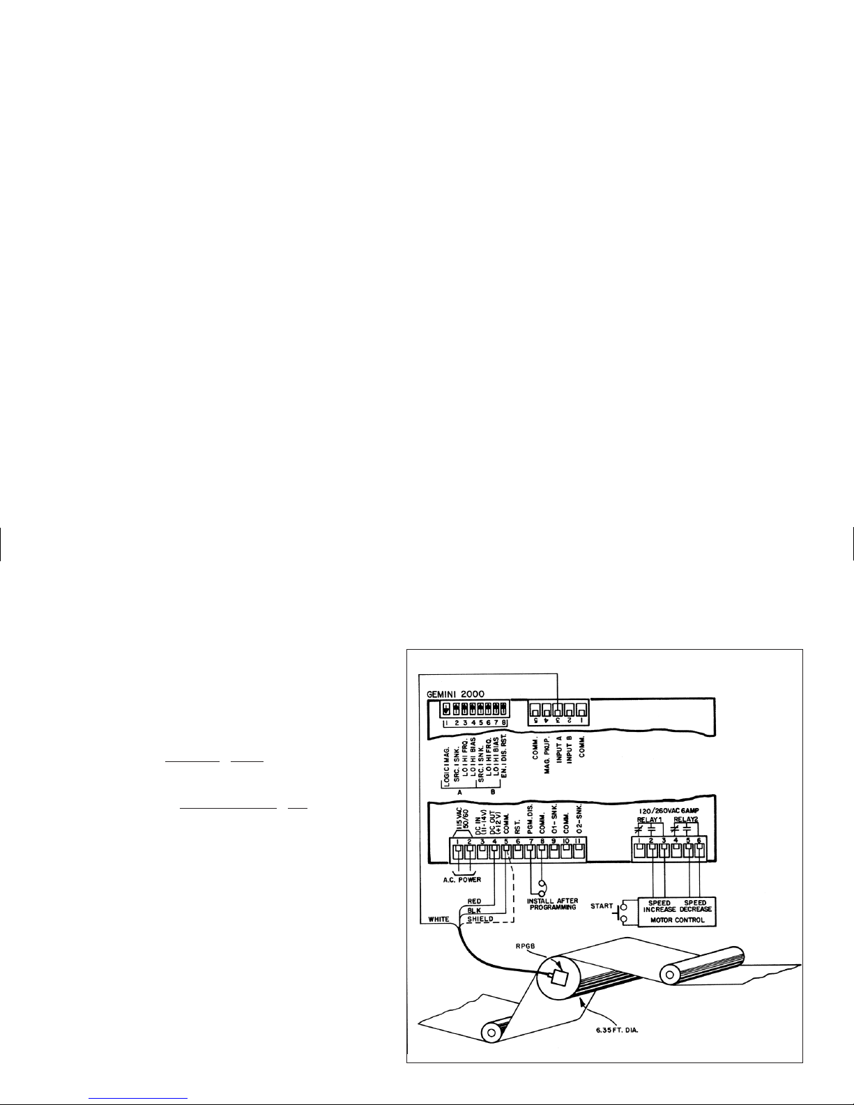
DUAL PRESET RATE PROGRAMMING APPLICATION EXAMPLE
A typical industrial Dual preset rate indicator application would be the
speed control of a web press operation in a newspaper plant. The Gemini
2000 as pictured, is programmed to read out in feet/min. every two seconds.
The input is from the rotary pulse generator that is attached on thedrive roll.
In this case, the RPG is delivering 120 pulses/rev. and the circumference of
the rollis 6.35 ft. Bysubstituting in our formulasas shown in Appendix“E”,
the correct parameters are determined.
FORMULA [A]
PPS
=
RPM x PPR=1 x 120=2 PPS
60 sec. 60
FORMULA [B]
SCALE FACTOR
=
DESIRED READING=6.35=1.5875
PPS x SAMPLE TIME 2x2
By programming a 1.5875 Scale Factor and a 2-second sample time, the
Gemini 2000 will display the FPM of the roll every 2 seconds. If added
resolution is desired, the number of count edges could be changed to 2, and
the scale factor would become 0.7938.
The drive mechanism of the roll will react to a contact closure to increase
or decrease speed at a set rate for the duration of the closure. The 2-second
sample time with a 0.5 second closure (Time delay) at the beginning of each
sample time, will allow the web process to remain within the lower and
upper tolerances. In this application, the lower speed limit is 500 FPM and
the upper limit is 700 FPM. When time delay output termination modes are
used in the Gemini 2000, Output 1 activates when the rate is lower than
Preset 1 and Output 2 activates when the rate is higher than Preset 2. With
this in mind, Output 1 is connected to the speed increase drive and set to the
lower limit and Output2 is set to the upper limit ofthe speed range. When the
rate drops below 500 FPM for the 2-second sample time, Output 1 will
activate for0.5 seconds. Conversely, when therate exceeds 700 FPMfor the
2-second sample time, Output 2 will activate for 0.5 seconds.
Page 23

HARDWARE SET-UP
The application drawing shows how the hardware for this system is to be
connected. The Red (supply), Black (Common), and White (signal) leads of the
RPG Cable are connected to the “DC OUT”, “COMM.”, and “INPUT A”
terminals respectively. The shield of the cable is connected to “COMM.”. The
normally open contact of Relay 1 is connected to the “Speed Increase Control”
and the normally open contact of Relay 2 is connected to the “Speed Reduction
Control”.A“Start” button isusedto start up the system andget it “up to speed”,
at which point the Gemini 2000 can take over and control the speed. After
programming is completed, a jumper is placed between the “COMM.” and
“PGM. DIS.” terminals of the unit. This terminal, working in conjunction with
the “Operator Accessible Functions” mode, will prevent accidental changes in
the unit’s operating modes.
The Input DIP Switch position 1 is set to the LOGIC position since an RPG is
being utilized. Position 2 is set to “SNK.”, which provides an internal pull-up
resistor to +12 VDC.(The RPGB has an open collector sinking output.) Position
3 is set to “HI FRQ.” sincethe input rate will be over 100 cps. Position 4 is set to
“HI BIAS” to provide higher noise immunity. Because Input B is not used, the
settings of Positions 5-7 are all selected as shown to provide maximum noise
immunity. Position 8 is setto “DIS. RST.”to disable thefront panel resetbutton.
For more detailed descriptions of the Input switch set-up, see Appendix “A”.
STEP BY STEP PROGRAMMING OF THE Gemini 2000
The steps for programming the Gemini should be followed in this order each
time a changeis made in a basicparameter of the system. (Thepreset value, scale
factor value and output time delay value can be changed at any time or in any
sequence, provided the unit is already operating in a valid mode, and an
“Operator Accessible Functions” mode is not preventing this change.)
Refer to the programming section, for instructions in programming function
codes and entering Scale Factor and Preset Values.
STEP 1 - Enter code 41 (Unit Personality), and a mode identifier of 2 for a rate
indicator unit personality.
STEP 2 - Enter code 44 (Number of Count Edges), and enter 1 for single edge
counting.
STEP 3 - Enter code 45 (Scale Multiplier Values),and enter a mode identifierof
1 for a scale multiplier of 1.
STEP 4 - Enter code 46 (Decimal Point and Leading Zero Blanking) and enter 1
for no decimal points and lead zero blanking.
STEP 5 -Enter code 52 (Output1Termination Modes) and enter5 for time delay
operation.
STEP 6 - Enter code 53 (Output 1 Time Delay) and enter a time delay value of
0000.50.
STEP 7 - Enter code 54 (Output 2 Termination Modes) and enter a mode
identifier of 5 for time delay operation.
STEP 8 - Enter code 55 (Output 2 Time Delay) and enter a time delay value of
0000.50.
STEP 9 - Enter code 61 (Right-Hand Dummy Zeros) and enter an identifier of 4
for no right-hand dummy zeros.
STEP 10 - Enter code 63 (Sample Time) and enter a mode identifier of 2 for a 2
second sample time.
STEP 11 -Press “P”(1). Enter the lower speedlimitforPreset 1 which is 000500
for this application.
STEP 12 - Press “P”(2). Enter the upper speed limit for Preset 2, which is
000700 for this application.
STEP 13 - Press “SF”(3). Enter the Scale factor for this application which is
1.5875.
STEP 14 - Entercode 66 (“Operator Accessible Functions” mode) andenter a -1
for all Operator Functions disabled. For this application the Scale Factor and
speed limits are fixed and do not require changing. Also there is no need to
reset the Sample time so Reset is locked out. (Note: After this code is
programmed, the “PGM. DIS.” terminal is connected to “COMM.” to
prevent any accidental changes.)
Page 24
GEMINI 2000 20 mA CURRENT LOOP COMMUNICATIONS
The Gemini 2000 20 mA Current Loop Communications Option allows a
“two-way” serial communications link to be established in order to monitor or
change the count value, Presets and Scale Factor from a remote location. Some
typical devicesthatcan be connected with theGemini 2000 are: a printer,terminal,
programmable controller, or host computer. For devices that use RS232, a
GCM232 SerialConverter Module is available toconvert the 20 mACurrentLoop
signals to RS232 andvice-versa. Also, a BCD converter is available to convert the
20 mA current loop signals, from the Gemini, to full parallel BCD, enabling the
Gemini to operate with Programmable Logic Controllers, etc.
There are two loops that must be established. One for sending commands to the
Gemini 2000 and one for receiving the data values from the Gemini 2000. Up to
sixteen Geminis or other RLC units with 20 mA serial communication capability,
can be connected togetherin the “loop” if a 24 V external currentsource is utilized.
A maximum of seven units can be installed in the loop if the Gemini’s 20 mA
current source is used. The units are assigned addresses by setting the Serial DIP
Switches on each unit. The applications can be as simple as attaching a printer to
obtain hardcopy of the displayinformationor as involved as using ahostcomputer
to automatically set up Presets and Scale Factors on a number of Geminis.
With the Communications Option, the following functions can be performed:
1. Interrogation of the Count Value, Presets, and Scale Factor.
2. Changing of the Presets and Scale Factor.
3. Resetting of the Count Value and Outputs.
4. Automatic print-out when using a printer and the “Print Request” Terminal.
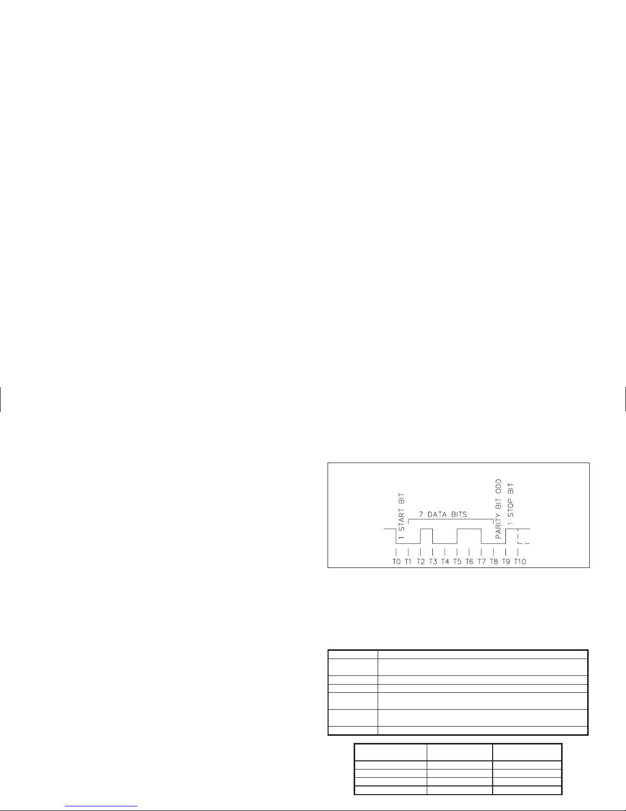
COMMUNICATION FORMAT
Data is sent by switchingoff and on the current in the 20 mAcurrent loop. Data
is receivedby monitoring the switchingaction and interpreting the codes that are
transmitted. In order for data to be interpreted correctly, there must be identical
formats and Baud Rates.
The format that theGemini 2000 will accept is:1 start bit, 7 databits, 1 odd parity
bit, and 1 stop bit. The Baud Rates that are available are: 300, 600, 1200 and 2400.
The selection of the Baud Rate is done by setting DIP switches. Refer to the
“Current Loop Installation” section, for set-up instructions.
SENDING COMMANDS & DATA TO THE GEMINI 2000
When sending commands to the Gemini 2000, a command string must be
constructed. The command string may consist of command codes, value
identifiers, and numerical data. Following is a list of commands and value
identifiers that are used when communicating with the Gemini 2000.
COMMAND DESCRIPTION
N (4EH) Address command; followed by a one or 2 digit unit address
number 1-15 and one of the following commands.
P (50H) Transmit per Print Options command.
R (52H) Reset command
T (54H) Transmit Value command; followed by a value identifier
(A-D); operates on count value, Presets and Scale Factor.
V (56H) Change Value command; followed by a value identifier (A, B,
D); operates on Scale Factor and Presets.
X (58H) Transmit and reset count command.
VALUE
IDENTIFIER
DESCRIPTION MNEMONIC
A (41H) Preset 1 (PS1)
B (42H) Preset 2 (PS2)
C (43H) Count Value (CNT)
D (44H) Scale Factor (SCF)
FIG. 1: DATA FORMAT-10 BIT FRAME [300, 600, 1200, 2400 Baud]
Page 25

The command string is constructed by using the above commands and value
identifiers, along with the data values that are required. Data values may or may
not contain the decimal point if a decimal point is programmed into the Gemini
2000. The Gemini 2000 will accept the decimal points, however, it does not
interpret them in any way. Leading zeros can be eliminated, however, all trailing
zeros must be present. For example, if a Scale Factor of 1.0000 is to be sent, the
data value can be transmitted as 1.0000 or 10000. If a “1” is transmitted, the
Scale Factor will be changed to 0.0001.
The Addresscommand is usedto allow a command to be directed to a specific
unit in the Serial Communications Loop. Whenever the unit address is zero,
transmission of the Address command is not required. This is done for
applications which do not require more than one Gemini. For applications that
require several units, it is recommended that each unit in the loop be given a
separate address. If they are given the same address, a command such as the
Transmit Value Command, will cause all the units to respond at the same time,
resulting in erroneous data.
The commandstringis constructed in aspecific logical sequence. The Gemini
2000 willnot accept command strings that do not follow this sequence.Only one
operation can be performed per command string. Below is the procedure to be
used when constructing a command string.
1. If the Gemini 2000, to which the command is to be sent, is assigned an
address other than zero, the first two or three characters of the command
string must consist of the Address Command (N) and theaddress numberof
the unit (1-15).
2. The next character(s) in the command string is the actual command that the
Gemini 2000 is to perform and the value identifier if it pertains to the
command. (A command such as the Transmit per Print Options, “P”,
command does not require a Value Identifier.)
3. If the change command is being used, the next characters in the command
string are the numerical data value.
4. The last character in the command string is the command terminator (*). This
character must be sent in order to tell the Geminis that the command string is
complete, so that they can begin processing the command.
Below are some typical examples of properly constructed command strings.
(EX. 1) Change Preset 1 on the Gemini 2000 with an address of 2 to 00123.4.
COMMAND STRING: N2VA1234*
(EX. 2) Have the Gemini 2000, with an address of 13, transmit the Count value.
COMMAND STRING: N13TC*
As shown, all commands must be terminated with a “Command Terminator”
(* or 2AH). The Gemini 2000 will not process the command until the terminator
is sent. If illegal commands or characters are sent to the Gemini 2000, they still
would need to be terminated by an (*). If they are not terminated, the next
command will not be accepted.
When writing application programs in Basic, the transmission of spaces or
carriage return andlinefeed should be inhibited by usingthesemicolon delimiter
with the PRINT statement. The Gemini 2000 will not accept a carriage return or
line feed as valid characters. (Refer to thelisting of a terminal emulation program
which is written in Basic.)
When a “ChangeValue” command is sent tothe Gemini 2000, a shortamount
of time is required for the unit to process the data. This time increases with the
count rate. During this time, only one additional command may be sent to the
Gemini 2000. This may be done 80 msec after the transmission of the “Change
Value” command. After the second command has been transmitted,the unit will
ignore any further commands until 10 msec after both the “Change Value” and
second command have been processed. It is recommended that a “Transmit
Value” command follow a “Change Value”command. If this is done, the
reception of the data can provide a timing reference for sending another
command and will insure that the change has occurred.
The timing diagrams show the timing considerations that need to be made.
FIG. 2: TIMING FOR SENDING COMMANDS
FIG. 3: TRANSMIT COUNT & RESET COMMAND TIMING
(**) This is the time that it takes the Gemini 2000 to process the preset.
It varies with the Count Rate and Scale Factor Value.
Page 26

RECEIVING DATA FROM THE GEMINI 2000
Data is transmitted from the Gemini 2000 when a “Transmit Value” or
“Transmit per Print Options” command is sent to the unit, or when the “PRINT
REQ.” terminal is activated. The Gemini 2000 can transmit 4 values: Count
value, Presets1&2,andScale Factor. A list of the abbreviations used when the
Gemini 2000 transmits the values are shown below.
CNT - Count Value
PS1 - Preset 1
PS2 - Preset 2
SCF - Scale Factor
A typical transmission, with the “PR.ID” (Print ID) switch in the up position,
is shown below.
The first two digits transmitted are the unit address followed by two blankspaces.
If the unit address is 0, the first locations will be left blank. The next three letters are
the abbreviation for the mnemonic value followed by one blank space. The actual
values are transmitted last. Negative values are indicated by a “-” sign. For positive
values, the “+” sign is not transmitted. Overflowed count values are shown by an
asterisk preceding the most significant digit of the value. The decimal point position
will “float” within the data field depending on the actual value it represents.
For peripheral control purposes, a single line transmission will have a <CR>
attached to the end of the above string. For a “T” command or each line of a block
transmission, only the above character string is sent. For the last line of a block
transmission, a <SP> <CR> <LF> is attached to the end of the above character string.
An example of a typical serial transmission:
3 CNT -1234.56 < CR> < LF>
If the “Print Request” terminal initiates the transmission, a 400 msec delay is
inserted before the transmission to keep multiple transmissions from
overrunning the printer.
When the Print ID switch is in the down position, the unit will not transmit the
characters before the data value (address, Value ID, spaces) or the 400 msec
printer delay. The same above value when transmitted with the “PR.ID” switch
in the down position, is transmitted as: -1234.56 < CR> < LF>
Note: When using the Gemini with a printer, with the “Print ID” switch in the
down position, some printers(otherthanthe RLC DMPC) may not work, since
the printer delay is not transmitted.
PRINT OPTIONS
The various Print Options are used mainly in conjunction with a printer andthe
Print Request Terminal. They provide a choice of Gemini 2000 data values to be
printed when either the Print Request Terminal is activated or the “Transmit per
Print Options” (P) command is sent to the Gemini 2000. The various Print
Options available are:
1. Print Count Value Only
2. Print Count Value & Presets
3. Print Count Value & Scale Factor
4. Print Count, Presets, & Scale Factor
A typical printout isshown below. The Print Options are selected bysetting S4
and S5 on the Serial DIP Switch. See “Serial DIP Switch Set-up” section for the
various switch settings.
1 CNT 000054
1 PS1 000100
1 PS2 000200
1 SCF 01.0000
The Transmit Count and Reset action of the (X) command is available for use
with thePrint Options. This optionis selected by setting the TRST switch (Serial
switch position 6) in the down position. This capability is useful in a totalizing
application wherea “shift total” is desiredwithout shutting down themachine to
take the reading and reset the unit.
FIG. 4: TRANSMIT COUNT & RESET (TRST) PRINT OPTION TIMING
Page 27

CURRENT LOOP INSTALLATION
WIRING CONNECTIONS
When wiring the 20 mA current loop, remove the 7-position terminal block
(TBD), locatedon the right sideof the top board.Refer to the numberslisted with
the terminal descriptions below or on the top label, and install each wire in its
proper location on the terminal block. When all connections are made, replace
the terminal block into its proper location.
It is recommended that shielded (screened) cable be used for serial
communications. This unit meets the EMC specifications using Alpha #2404
cable or equivalent. There are higher grades of shielded cable, such as, four
conductor twisted pair, that offer an even higher degree of noise immunity.
TERMINAL DESCRIPTIONS FOR TERMINAL BLOCK TBD
1. -20 mA SRC (COMMON) - Common for 20 mA SRC & Print Request
terminal.
2. PRINT REQUEST - The Print Request Terminal is connected to common to
request the Gemini 2000 to transmit according to the Print Options mode that
has been selected. (Minimum Activation time = 25 msec.)
3. +20 mA SRC- The 20 mA SRC terminal providesthe source current for one of
the loops.
4. SO- (Serial Out-)
5. SO+ (Serial Out+)
The Gemini 2000 transmits the requested data on these terminals (SO- &
SO+). They are connected in series to the receive input of the device to be
connected.
6. SI- (Serial In-)
7. SI+ (Serial In+)
The Gemini 2000 receivescommands on these terminals (SI- & SI+).They are
connected in series with the transmit or output terminals of the device to be
connected.
Note: The serial input terminals must be held in the mark condition
(current on) in order for the Gemini 2000 to respond to a Print Request
terminal activation.
Page 28

CURRENT LOOP INSTALLATION (Cont’d)
SERIAL DIP SWITCH SET-UP
The SerialDIP switches are accessiblethrough the side ofthe Gemini 2000. A
list of the DIP switch positions and their functions are shown in Figure 5.
BR0 & BR1, BAUD RATE - Set-up is shown in Figure 5, below. When
changing the Baud Rate, the unit should be powered-down and then powered
back up again. The unitwill only recognize a baud rate change uponpower-up,
after activating the “Print Request” terminal or after a few characters have
been sent at the new baud rate (If the two previous conditions have not
occurred, the Geminiwillsee the characters as erroneousandit will check the
baud rate and set itself to operate at the new rate).
PR.ID - PRINT ID. - When this switch is in the up position, the Gemini 2000
will print the unit address, data value ID and the data value when a
transmission is requested. The unit will also insert a 400 msec delay between
transmissions when the “P”command or Print Request terminal is used. This
switch position is generally used when the unit is connected with a printer.
When the switch is in the down position, the Gemini 2000 will transmit only the
data value, without the unit address and data ID. The 400 msec delay, described
above, willnot be inserted. Thisswitch position usage isintended for applications
where the Gemini is communicating with a computer. In these circumstances
printing the address and value ID and inserting a 400 msec print delay is usually
unnecessary and needlessly slows down communication throughput.
PC0 & PC1, PRINT OPTIONS - Used to control which values are transmitted
when the Print Request terminal is activated or when the Transmit per Print
Options command “P” is sent to the Gemini 2000.
TRST, TRANSMIT CNT & RESET - Used in conjunction with Print Options.
When this switch is inthe down position,the unit willtransmit and reset thecount
when the “PRINT. REQ.” terminal is activated or the (P) command is received.
AD0, AD1, AD2 & AD3, UNIT ADDRESS - These switches are used to give
each unit aseparate address when more than oneunit is connected in theLoop.
See Figure 5, for Switch Set-up.
FIG. 5: DIP SWITCH SET-UP
When connecting a printer or any
device in whichthe Gemini 2000’s Serial
Inputs (SI+, SI-) are not used, they must
still be connected to a 20 mA source and
be in the Mark condition (Current on) in
order forthe Gemini 2000to respond toa
Print Request.
Page 29

COMMUNICATIONS APPLICATIONS
In multiple Gemini hookups, the “+20 mA SRC” terminal of two Geminis provide
the 20 mA source current for both the Serial Input loop and Serial Output loop. When
more than one unitis connected to a printer,only one Gemini can transmit data at any
given time. If another Print Request terminal is activated while the printer is still
printing, two Geminis will transmit to the one printer at the same time, resulting in a
“garbled” print-out.
In both configurations,theBaud rate switches of theGemini(s)are to be set to1200
baud. Refer to “Current Loop Installation” section to set up the Baud Rate, Print
Options, and UnitAddress.The DMPC printer has beenfactoryset to operate with the
Gemini 2000 and does not require any set-up.
CONNECTING TO AN RLC PRINTER
One or several Gemini 2000s (with Serial Communications
option) can be set up to operate with an RLC Model DMPC
printer. The two applications show the wiring diagrams for single
and multiple Gemini hookups to the printer. Both loops (transmit
and receive) are used with the Model DMPC printer. The printer
sends a busy signal on the Gemini’s receive loop, which prevents
the Gemini from overrunning the printer. In the single Gemini
hookup, the “DC OUT” terminal, current limited with a 680 ohm
resistor (provided with the printer), is used to obtain the source
current for the GeminiSerialOutputloop. The Gemini’s “+20 mA
SRC” terminal provides the current for the Serial Input Loop.
Page 30
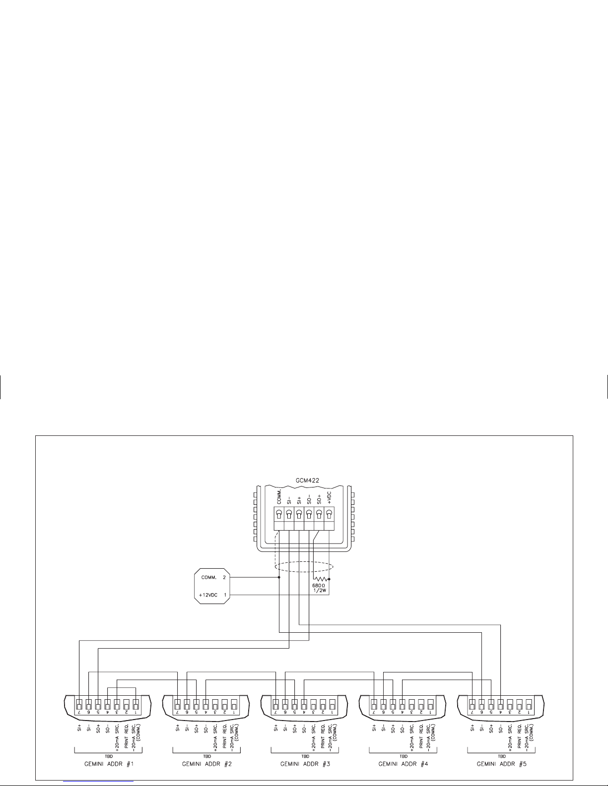
PROCESS MONITORING SYSTEM
Five Gemini 2000s with 20 mA Current Loop Option, are
used to monitor and control parts packaging machines in a
plant. The units are located at each of the machines in the
production area of the building. The communications lines are
run to an Industrial computer located in the production offices.
[OTHER GEMINIS OR RLC PRODUCTS WITH 20 MA CURRENT LOOP
CAN BE CONNECTED IN THE SAME LOOP.]
The drawing below shows the Current Loop set-up. Each
Gemini 2000is given an address andthe Serial DIP switchesare
set accordingly. A Baud Rate of 1200 is selected and set in each
of the Gemini 2000s. An application program is written, which
sends and retrieves data from the units using the Change and
Transmit Value commands.
Note: A Serial Converter Module is
available for interfacing an RS232
device to Geminis.
Page 31

TROUBLESHOOTING GEMINI SERIAL COMMUNICATIONS
If problems are encountered when trying to get the Gemini(s) and host device or
printer to communicate, the following checklist can be used to help find the solution.
1. Checkall wiring. Refer to theprevious application examples anduse them as a
guide to check your serial communication wiring. Proper polarity of all
Geminis and other peripheralsmust be observed. If a multimeter or ammeteris
available, insert it in series in eachSerial loop and check for current flow with
all units powered up. If no current is flowing, either the loop is not wired
correctly, or some other fault has occurred. If too much current has been sent
through a SerialInput or Output, the unitmay have been damaged. Ifa Gemini
is suspected, it can be tested for operation by using the Serial Loop-back test
described in the next section.
2. If the Gemini is set-up with a“host computer”, device or printer (other than the
RLC DMPC),check to make sure thatthe computer or device isconfigured with
the same communication format as the Gemini. The only communication
format the Gemini will accept is; 1 start bit, 7 data bits, odd parity, and 1 stop bit.
3. Checkthe baud ratesettings and makesure all devicesin the loopare set to the
same baud rate.
4. Check the Gemini’s unit address. If the Address command is not used when
transmitting acommand to the Gemini,the Gemini’s addressmustbe set to0.See
“Sending Commands & Data to the Gemini” section for command structure.
5. If two-way communications are to be established between the Gemini and a
computer, try getting the computer to receive transmissions from the Gemini
first. The Gemini’s “PRINT REQ.” terminal can be used to initiate the
transmissions from the Gemini.
6. When sending commands to the Gemini, the * (2Ah) must terminate the
command. NO CARRIAGE RETURNS (0Dh) OR LINE FEED (0Ah)
CHARACTERS SHOULD BE SENT TO THE GEMINI. If they are sent, the
Gemini will not respond to the next command.
7. Forapplications where 1200Baud or loweris used, the command terminator (*)
can be sent before the string to eliminate any illegally transmitted characters.
SERIAL LOOP-BACK SELF-TEST
The Gemini 2000 has a Serial Loop-back Self-test feature. This test enables the
user toverifythe operation of the Geminiwhen problems are encountered tryingto
get theGemini and “Host device” communicating. In thistest, the Gemini’s Serial
Input and Output Loops are connected together with the 20 mA source supplying
the loop current. The Gemini then transmits data “to itself”. If the data is received
properly, the Gemini 2000will change its Scale Factor valueto 0.1111. To perform
the loop-back test, follow the test sequence as described below.
1. With the unit powered down, wire up the serial terminal block, “TBD”,as
shown in the diagram below.
2. Set the Gemini’s unit address to 15 (set switches 7-10 of the Serial DIP Switch
to the down position).
3. Apply power to the unit. On power-up the Gemini will perform the loop-back
test. To check the results: Call up the Scale Factor value by pressing the “SF”
key. If the Serial loop is functioning properly the Scale Factor value will be
0.1111. If this result is not obtained, double check the connections with those
shown in the diagram, and the unit address switch positions and repeat step 3.
4. If the connection between the Print Request terminal, “PRINT REQ.” and
“COMMON” is disconnected while the unit is under power, the Scale Factor
value will change back to its previous setting.
If the unit does not pass this test, contact your local Red Lion Controls
distributor.
Page 32

The Gemini is intended to be mounted into an enclosed panel with a gasket
to provide a water-tight seal. The unit meets NEMA 4/IP65 requirements for
indoor use when properly installed. Two mounting clips and screws are
provided for easy installation. Consideration should be given to the thickness
of thepanel. Too thin ofa panel may distortand not provide awater-tight seal.
(Recommended minimum panel thickness is 1/8".)
After the panel cut-out has been completed and deburred, remove the
backing from the adhesive side of the gasket, and carefully stick the gasket to
the panel. DO NOT
APPLY THE ADHESIVE SIDE OF THE GASKET TO
THE COUNTER BEZEL. Insert the unit into the panel. As depicted in the
drawing, install the screws into the narrow end of the mounting clips. Thread
the screws into the clips until the
pointed end just protrudes through
the other side. Install each of the two
mounting clips by inserting the wide
lip of the clipsintothewide end of the
holes located on either side of the
case. Tighten the screws evenly to
apply uniform compression, thus
providing a water-tight seal.
CAUTION: Only minimum
pressure is requiredto seal panel. Do
NOT
overtighten mounting screws.
APPENDIX “A” - INSTALLATION & INPUT CONFIGURATION SWITCH SET-UP
Before installing the Gemini into the panel, the user should first become
familiar with the unit. It may also be desirable to program the unit for the
application at hand (Refer to the “Programming and Applications” sections).
Once theunit is programmed, thesettings will be saved in memory. TheProgram
Disable “PGM. DIS.” terminal should be connected to “COMM.” to prevent
accidental or unauthorized programming changes.
Installation Environment
The unit should be installed in a location that does not exceed the maximum
operating temperature and provides good air circulation. Placing the unit near
devices that generate excessive heat should be avoided.
The bezel should be cleaned only witha soft cloth and neutral soap product. Do
NOT use solvents. Continuous exposure to direct sunlight may accelerate the
aging process of the bezel.
Do not use tools of any kind (screwdrivers, pens, pencils, etc.) to operate the
keypad of the unit.
PANEL MOUNTING (Note, See Appendix “B” for Dimensions)
Page 33

GEMINI 1000 BLOCK DIAGRAM
Page 34

GEMINI 2000 BLOCK DIAGRAM
Page 35

SELECT AC POWER (115/230 VAC)
The AC power to the unit must be selected for either 115 VAC or 230 VAC.
The selector switch is located through an access slot on the side of the case (See
the Installation Figure on the previous page, or the label on the case). The unit is
shipped from the factory with the switch in the 230 VAC position.
Caution: Damage to the unit may occur if the AC selector switch is set
incorrectly.
EMC Compliance Installation
This unit complies with the Electromagnetic Compatibility (EMC) standards
listed in the specifications. Compliance to the EMC standards was demonstrated
by means of a test set-up using the following installation methods:
1. Unit mounted in a metal panel connected to earth ground (protective earth).
2. Shielded (screened)cables for Signal and Controlinputs with shield drain wire
connected to earth ground at the mounting panel only.
Multi-conductor Cable Function Used For
Belden #8771 - 3 conductor, #22 AWG
with foil shield and drain wire
Input A, Input B, PGM DIS,
and REM RST
Alpha #2404 - 4 conductor, #22 AWG
with foil shield and drain wire
20 mA serial option
Alpha #1173C - 3 conductor, #22 AWG
non-shielded
Relay Outputs and
Solid State Outputs
3. Metal bezel of unit connected to mounting panel with 9 inch (23 cm) ground
lead from rear bezel screw. Test: Immunity to ESD per EN 61000-4-2.
4. EMI filter (Shaffner FN610) placed on the DC mains cable for EMI
frequencies above 40 MHz when using optional power supply. Test: RF
Conducted Immunity EN 61000-4-6
Shield Termination
EMC compliance installation testing had the drain wire for the shielded cable
terminated as shown. The drain wire was less than 0.5" (12.7 mm) long.
Page 36

Additional EMC Installation Guidelines
Although this unit is designed with a high degree of immunity to
ElectroMagnetic Interference (EMI), proper installation and wiring methods
must be followed to ensure compatibility in each application. The type of the
electrical noise, source or coupling method into the unit may be different for
various installations. Listed below are some additional EMC guidelines for
successful installation in an industrial environment.
1. The unit should be mounted in a metalenclosure, which is properly connected
to protective earth.
a. If the bezel is exposed to high Electro-Static Discharge (ESD) levels,
above 4Kv, it should be connected to protective earth. This can be done
by making sure the metal bezel makesproper contact to the panel cut-out
or connecting the bezel screw with a spade terminal and wire to
protective earth.
2. Use shielded (screened) cables for all Signal and Control inputs. The shield
(screen) pigtail connection should be made as short as possible. The
connection point for the shield depends somewhat upon the application.
Listed below are the recommended methods of connecting the shield,in order
of their effectiveness.
a. Connect the shield only at the panel where the unit is mounted to earth
ground (protective earth).
b. Connect the shield to earth ground at both ends of the cable, usually
when the noise source frequency is above 1 MHz.
c. Connect the shield to common of the unit and leave the other end of the
shield unconnected and insulated from earth ground.
3. Never run Signal or Control cables in the same conduit or raceway with AC
power lines, conductorsfeedingmotors, solenoids, SCR controls, and heaters,
etc. The cables should be run in metal conduit that is properly grounded. This
is especially useful in applications where cable runs are long and portable
two-way radios are used in close proximity or if the installation is near a
commercial radio transmitter.
4. Signal or Control cables within an enclosure should be routed as far away as
possible from contactors, control relays, transformers, and other noisy
components.
5. In extremely high EMI environments, the use of external EMI suppression
devices, such as ferrite suppression cores, is effective. Install them on Signal and
Control cables as close to the unit as possible. Loop the cable through the core
several times or use multiple cores on each cable for additional protection.
Install line filters on the power input cable to the unit to suppress power line
interference. Install them near the power entry point of the enclosure. The
following EMI suppression devices (or equivalent) are recommended:
Ferrite Suppression Cores for signal and control cables:
Fair-Rite # 0443167251 (RLC #FCOR0000)
TDK # ZCAT3035-1330A
Steward #28B2029-0A0
Line Filters for input power cables:
Schaffner # FN610-1/07 (RLC #LFIL0000)
Schaffner # FN670-1.8/07
Corcom #1VR3
Note: Reference manufacturer’s instructions when installing a line filter.
6. Long cable runs are more susceptible to EMI pickup than short cable runs.
Therefore, keep cable runs as short as possible.
7. Switching of inductive loads produces high EMI. Use of snubbers across
inductive loads suppresses EMI.
Snubbers:
RLC #SNUB0000
WIRING CONNECTIONS
After the unit has been mechanically mounted, it is ready to be wired. All
conductors should meet voltage and current ratings for each terminal. Also
cabling should conformtoappropriate standards of good installation,localcodes
and regulations. Itisrecommended that power supplied to theunit(AC or DC) be
protected by a fuse or circuit breaker.
All wiring connectionsaremadeon removable plug-in terminal blocks. Thereis
a separate terminal block for the count inputs, bottom board, optional relay board,
and optional20 mA currentloop. When wiringthe unit, remove the terminal block
and refer to the “Block Diagram” to identify the terminal block position number
with the proper function. Simply strip the wire, leaving approximately 1/4" bare
wire exposed(standardwires should be tinned withsolder). Insert thewireinto the
terminal andtighten down the screwuntil wire is clampedin tightly. Each terminal
can accept up to two 18-gauge wires. After the terminal block is wired, install in
proper location on board. Wire each terminal block in this manner.
Page 37

PRIMARY A.C. POWER WIRING
For best results, the A.C. primarypower should be relatively “clean” and within
the specified +/-10% variation limits. Drawing power fromheavily loaded circuits
or from circuits that also power loads that cycle on and off, should be avoided.
The AC poweris connected to the bottom left terminals TBA1&2,marked as AC
Power, 50/60 Hz. The voltage selector switch, located on the side of the unit, is used
to select the proper voltage. The switch is a slide movement type and can be set by
using asmallscrewdriver.Ifthe switch is towards thefront of theunit,itis set for 230
VAC input. The switch is in the 230 VAC position when shipped from the factory.
Note: Beforeapplyingpower to the unit,make sure the AC powerselector switch
is set for the proper voltage setting.
USING AN EXTERNAL POWER SOURCE
The Gemini can be operated from a D.C. power source that provides 11-14
VDC at the units rated power consumption. The power source can be a 12 V
battery or an external power supply that is capable of supplying the unit’s rated
current. It is not necessary to provide battery backup to retain count information.
The Gemini has an internal memory in which the count is stored upon
power-down. Refer to the “Block Diagrams”.
Relay Wiring
To prolong contact life and suppress electrical noise interference due to the
switching of inductive loads, it is good installation practice to install a snubber
across the contactor. Follow the manufacturer’s instructions for installation.
Note: Snubber leakagecurrent can cause someelectro-mechanical devices to be
held ON.
SERIAL COMMUNICATIONS
The Gemini 2000 can be purchased with 20 mA Current Loop Option. On
these units, refer to the 20 mA Current Loop section for installation and
operational procedures of the Serial loop.
INPUT A & MAGNETIC PICKUP INPUT
The Magnetic Pickup Input and Input A utilize some common circuitry. For
this reason the Input A switches are used to set up both Magnetic Pickup and
Logic Input A. S1 selects between Magnetic Pickup Input or Logic Input A.
WHEN THEMAGNETIC PICKUP INPUT ISBEING USED, S2 MUST BE IN
THE SNK POSITION or the unit will not count.
S3 (HI/LO FRQ) and S4 (HI/LO BIAS) do not affect the Magnetic Pickup
Input. When S1 is in the Logic position, the Magnetic Pickup Input is disabled
and Input A can be used.
INPUT B
Input B is designed specifically for Logic type inputs. It is identical to the
count input of SC Series counters. When Input A is set up for Logic operation,
both InputA and InputB operate identically. S5, S6, and S7 function the same as
S2, S3, and S4.
Page 38
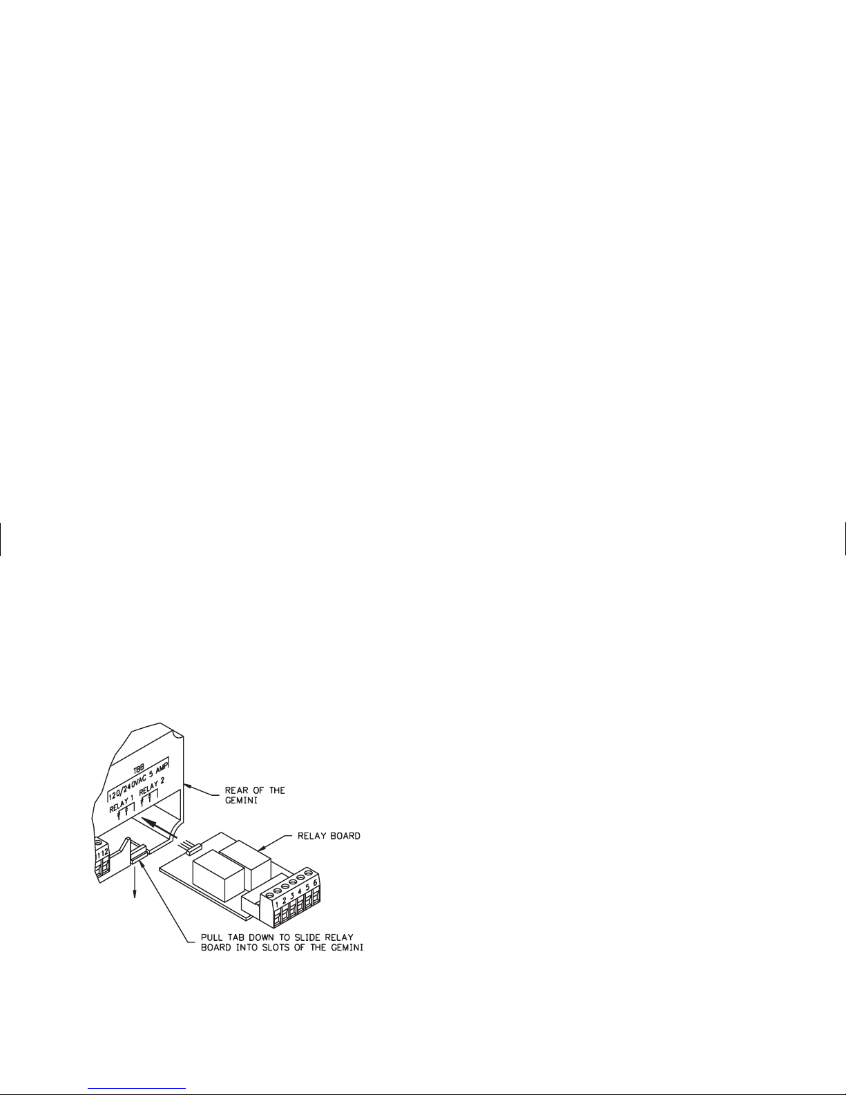
INSTALLATION & REMOVAL OF THE RELAY BOARD
To install the relay board, locate the relay opening at the lower right-hand
corner, on the back of the Gemini. Pull the tab down while sliding the board into
the two slots in the housing. The relay board will seat into the unit, allowing the
tab to return to its original position. To remove the relay board, pull down on the
tab just enoughto allow the relay board toslide out. Grasp the terminal connector
and slowly pull until the relay board is removed.
NOTES:
1. SENSOR VOLTAGE AND CURRENT
The +12 V sensor supply voltage on the “DC OUT” terminal is nominal with
+/-25% variation dueto line and internal loadvariations. All RLC sensors will
accommodate this variation.
2. HI/LO FRQ SELECTION
The HI/LO FRQ selection switch must be set on “LO FRQ” when switch
contacts are used to generate count input signals. Since the “LO FRQ” mode
also provides very high immunity against electrical noise pickup, it is
recommended that this mode also be used, whenever possible, with electronic
sensor outputs. The “LO FRQ” mode can be used with any type of sensor
output, provided pulsewidths never decrease below 5msec, and the count rate
does not exceed 100 cps.
3. V
IL
and VIHlevels given are nominal values +/-10% when the voltage on “DC
OUT” terminal is +12 VDC. These nominal values will vary in proportion to
the variations in the “DC OUT” terminal voltage, which are caused by line
voltage and load changes.
4. When shielded cable is used, the shield should be connected to “COMM.” at
the counter and left unconnected at the sensor end.
5. Input B set-up is identical to that of Input A. Input B is for Logic Inputs only.
6. Inputs A and B can accept source pulses from other circuits up to +28 V in
amplitude. For voltages above +28 V, a limiting resistor and zener diode
should be used to limit the voltage at the input.
Page 39

GEMINI 1000 CONNECTIONS & CONFIGURATION SWITCH SET-UPS FOR VARIOUS SENSOR OUTPUTS (SEE NOTE 5)
Page 40

GEMINI 2000 CONNECTIONS & CONFIGURATION SWITCH SET-UPS FOR VARIOUS SENSOR OUTPUTS (SEE NOTE 5)
Page 41

GEMINI 1000 SENSOR INPUT CONNECTIONS & INPUT CONFIGURATION SWITCH SET-UP
The accompanying diagram shows the details of the count Input A and
magnetic pickup circuit. The schematic circuit for Input B is almost identical to
that of Input A, with the exception that Input B does not have the Magnetic
Pickup circuitry paralleled with it. The four switches used to set up Input A and
the Magnetic Pickup are designated S1, S2, S3, and S4. To set up Input B; use
switches S5, S6, and S7. The functions of these switches are as follows:
S1 - MAG: Enables the Magnetic Pickup terminal to be used.
LOGIC: Disables the Magnetic Pickup Input.
Note: SWITCH S2 MUST BE IN THE “SNK” POSITION FOR
MAGNETIC PICKUP INPUT.
S2 - SNK: Provides a 7.8 K pull-up resistor for sensors with sinking
outputs.
SRC: Provides a 3.9 K pull-down resistor for sensors with sourcing
outputs.
S3 - HI FRQ: Removes damping capacitor and allows operation up to
10 KHz. Minimum count ON/OFF times - 50 usec.
LO FRQ: Connects damping capacitor for switch contact debounce.
Limits count speed to 100 cps max. Min. count pulse ON/OFF time 5 msec.
S4 - HI BIAS:Sets input trigger levels atmid-range to accept outputsfrom
2-wire proximity sensors, resistive photo-cells, and logic pulses with
full 0 to +12 V swings. (V
IL
= 5.5 V, VIH= 7.5 V)
LO BIAS: Sets input trigger levels to the low range to accept logic
pulses with 0 to 5 V swings. (V
IL
= 1.5 V, VIH= 3.75 V)
S5 - Same as S2, for Input B - does not affect Magnetic Pickup Input.
S6 - Same as S3, for Input B.
S7 - Same as S4, for Input B.
S8 - DIS. RST.: Disables front panel reset.
EN. RST.: Enables front panel reset if “Operator Accessible
Functions” mode (Code 66) has Reset enabled.
CHAN. B CHANNEL A
Page 42
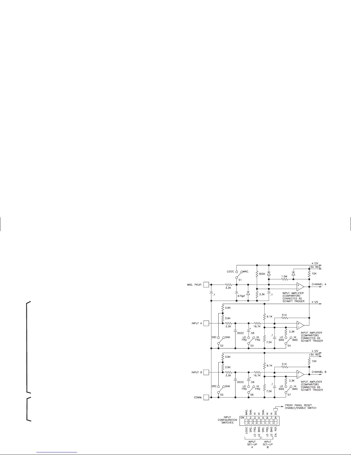
GEMINI 2000 SENSOR INPUT CONNECTIONS & INPUT CONFIGURATION SWITCH SET-UP
The accompanying diagram shows the details of the count Input A and
magnetic pickup circuit. The schematic circuit for Input B is almost identical to
that of Input A, with the exception that Input B does not have the Magnetic
Pickup circuitry paralleled with it. The four switches used to set up Input A and
the Magnetic Pickup are designated S1, S2, S3, and S4. To set up Input B; use
switches S5, S6, and S7. The functions of these switches are as follows:
S1 - MAG: Enables the Magnetic Pickup terminal to be used.
LOGIC: Disables the Magnetic Pickup Input.
Note: SWITCH S2 MUST BE IN THE “SNK” POSITION FOR
MAGNETIC PICKUP INPUT.
S2 - SNK: Provides a 7.8 K pull-up resistor for sensors with sinking
outputs.
SRC: Provides a 3.9 K pull-down resistor for sensors with sourcing
outputs.
S3 - HI FRQ: Removes damping capacitor and allows operation up to 10
KHz. Minimum count ON/OFF times - 50 usec.
LO FRQ: Connects damping capacitor for switch contact debounce.
Limits count speedto 100 cps max. Min.countpulse ON/OFF time - 5
msec.
S4 - HI BIAS:Sets input trigger levels atmid-range to accept outputsfrom
2-wire proximity sensors, resistive photo-cells, and logic pulses with
full 0 to +12 V swings. (V
IL
= 5.5 V, VIH= 7.5 V)
LO BIAS: Sets input trigger levels to the low range to accept logic
pulses with 0 to 5 V swings. (V
IL
= 1.5 V, VIH= 3.75 V)
S5 - Same as S2, for Input B - does not affect Magnetic Pickup Input.
S6 - Same as S3, for Input B.
S7 - Same as S4, for Input B.
S8 - DIS. RST.: Disables front panel reset.
EN. RST.: Enables front panel reset if “Operator Accessible
Functions” mode (Code 66) has Reset enabled.
CHAN. B CHANNEL A
Page 43

APPENDIX “B” - SPECIFICATIONS & DIMENSIONS
1. DISPLAY: 6-digit, 0.56" (14.2 mm) High LED display.
2. POWER REQUIREMENTS:
AC Power: Switch selectable 115/230 VAC (+/-10%), 50/60 Hz, 20 VA
DC Power: 11 to 14 VDC @ 0.7 amp maximum
3. SENSOR POWER: +12 VDC (+/-25%) @ 100 mA.
4. INPUTSA AND B: Switchselectable to accept count pulses from a variety of
sources including switch contacts, outputs from CMOS or TTL Circuits, and
all standard RLC sensors.
Current Sourcing - Unit provides 3.9 KW pull-down load for sensor with
current sourcing outputs. (Max. input voltage 28 VDC @ 7 mA.)
Current Sinking- Unit provides 7.8 KW pull-up load for sensorswith current
sinking outputs. (Max. sensor current 1.6 mA.)
Debounce -Damping capacitor provided for switch contact debounce.Limits
count rate to 100 cps max. and input pulse widths to 5 msec. min.
Lo Bias - Input trigger levels V
IL
= 1.5 V, VIH= 3.75 V
Hi Bias - Input trigger levels V
IL
= 5.5 V, VIH= 7.5 V
Note: Biaslevels given are +/-10% @ 12 VDC.They vary proportionally with
sensor supply voltage.
5. MAGNETIC PICKUP INPUT:
Sensitivity - 150 mV peak nominal
Hysteresis - 100 mV nominal
Input impedance - 26.5 KW @ 60 Hz nominal
Maximum Input Voltage - +/-50 Vp
6. MAXIMUM COUNT RATES:
Uni or Bi-Directional Modes - 9,000 cps, 8,000 cps (X2)
2-Input Anti-Coincidence Modes - 5,000 cps, 4,000 cps (X2)
Quadrature Modes - 5,000 cps (X1), 4,000 cps (X2 or X4)
Rate Indicator Version - 10,000 cps, 8,000 cps (X2)
7. CONTROL INPUTS:
Reset - Activelow (V
IL
= 1.5 Vmax.), internally pulled up to +12VDC(I
SNK
=
3 mA), Response time = 10 msec.
Program Disable - Active low (V
IL
= 1.5 V max.), internally pulled up to +5
VDC (I
SNK
= 1 mA).
8. SERIAL COMMUNICATIONS (Optional Gemini 2000 only):
Type - Bi-directional 20 mAcurrent loop, 20 mA source provided. (Powers up
to 7 units in a loop with internal current source.)
Baud Rate - Programmable 300 to 2400.
Maximum Address - 16 units (0-15). (Actual number in a single loop is
limited by serial hardware specifications.)
Data Format - 10 bit frame, Odd parity (onestart bit, 7 data bits, one odd parity
bit, and one stop bit.)
DIMENSIONS In Inches (mm)
Note: Mounted units require a clearance of 6.8" (W) behind the panel.
Page 44

8. SERIAL COMMUNICATIONS (Optional): (Cont’d)
Serial Hardware Specifications -
SO - Output Transistor Rating: V
max
= 30 VDC, V
SAT
=1V
max
at 20 mA.
(Can address 16 units in a loop)
SI - Input Diode Rating: VF = 1.25 V
TYP
; 1.5 V
max
Note: The compliance voltage rating of the source must begreater than the
sum of the voltage drops around the loop.
9. OUTPUT(S):
Solid-State - CurrentsinkingNPN open collector transistor(s). I
SNK
= 100 mA
maximum. V
OH
= 30 VDCmaximum (Internal Zener diode protection).VOL=
1 VDC max. @ 100 mA.
Relay(s) - Mountedonafield replaceable P.C. board. Form Ccontactsratedat
5 amps @ 120/240 VAC or 28 VDC (resistive load), 1/8 H.P. @ 120 VAC
(inductive load). The operatetime is 5 msec. nominal and the release time is 3
msec. nominal.
Relay Life Expectancy - 100,000 cycles at Max. Rating. (As load level
decreases, life expectancy increases.)
Programmable Timed Outputs - The timed outputs can be set from 0.01 to
599.99 seconds, +/-(0.01% + 10 msec).
10. CERTIFICATIONS AND COMPLIANCES:
SAFETY
IEC 1010-1, EN 61010-1: Safety requirementsfor electrical equipment
for measurement, control, and laboratory use, Part 1.
IP65 Enclosure rating (Face only), IEC 529
Type 4 Enclosure rating (Face only), UL50
ELECTROMAGNETIC COMPATIBILITY:
Immunity to EN 50082-2
Electrostatic discharge EN 61000-4-2 Level 2; 4 Kv contact
1
Level 3; 8 Kv air
Electromagnetic RF fields EN 61000-4-3 Level 3; 10 V/m
80 MHz - 1 GHz
Fast transients (burst) EN 61000-4-4 Level 4; 2 Kv I/O
Level 3; 2 Kv power
2
RF conducted interference EN 61000-4-6 Level 3; 10 V/rms
150 KHz - 80 MHz
Power frequency magnetic fields EN 61000-4-8 Level 4; 30 A/m
Emissions to EN 50081-2
RF interference EN 55011 Enclosure class A
Power mains class A
Notes:
1. Metal bezel of unit connected withground from rear bezel screw to metal
mounting panel.
2. When the unit is DC powered, a power line filter (RLC# LFIL0000 or
equivalent) was installed, so as not to impair the function of the unit.
Refer to the EMC Compliance Installation section of the manual for
additional information.
11. ENVIRONMENTAL CONDITIONS:
Operating Temperature: 0 to 50°C
Storage Temperature: -40 to 80°C
Operating and Storage Humidity: 85% max. relative humidity
(non-condensing) from 0°C to 50°C.
Altitude: Up to 2000 meters
12. CONSTRUCTION: Metal die-cast bezel, plastic case. This unit is rated
for NEMA 4/IP65 indoor use. Installation Category II, Pollution
Degree 2.
13. WEIGHT: 2.1 lbs (0.9 kg)
Page 45

APPENDIX “C” - TROUBLESHOOTING GUIDE
The majority of difficultiesarising with the Gemini 2000 are related to incorrect power hook-up and programming set-up.
Always check all connections, function codes, Scale Factor, and presets as a first step in troubleshooting.
Before applying power,doublecheck all wiring. Improper ACvoltageor AC connections may resultinpermanent damage
to the unit.
For further technical assistance, contact technical support at the numbers listed on the back cover of the instruction manual.
PROBLEM POSSIBLE CAUSE REMEDIES
NO DISPLAY 1. Power off, improperly connected, or power 1. Check all wiring, verify power.
brown-out.
P ON DISPLAY 1. Data error on power-up. 1a. Press “E” key.
b. Check all function codes.
E ON THE DISPLAY 1. Data error detected by processor. 1a. Press “E” key.
b. Check all function codes.
c. Check signal lines for possible noise sources.
RIGHT HAND DIGITS LOCKED TO ZERO 1. Right-hand zeros programmed. 1. Check function code 61 for dummy “0”
program.
NO RESPONSE TO FRONT PANEL 1. Panel disabled. 1. Consult manual on “Operator Accessible
Functions” modes.
UNIT DOES NOT COUNT 1. No input. 1. Check sensors/connections.
2. Input selected incorrectly. 2. Check rear panel DIP switches.
3. Wrong Personality. 3. Check function code 41 for counter mode.
4. Count Inhibit. 4. Check function code 43. If set for 1, when
Input B is low, count is inhibited.
5. If in Rate Mode, sample time not complete. 5. Allow sample time to complete
6. Scale Factor / Multiplier too small. 6. Check scale factor value and scale multiplier
values.
Page 46

APPENDIX “C” - TROUBLESHOOTING GUIDE (Cont’d)
PROBLEM POSSIBLE CAUSE REMEDIES
UNIT WILL NOT ACCEPT THE
DESIRED PRESET VALUE
1. When scale factors greater than 1 are used,
the preset value must be evenly divisible
by the scale factor value.
1. Unit automatically adjusts preset value to be
evenly divisible by the scale factor value.
UNIT COUNTS INCORRECTLY 1. Input type incorrectly selected. 1. Check rear panel DIP switches. Turn on
LO FRQ. switch for count speed of less
than 100 cps.
2. Inputs incorrectly connected or loose connections. 2. Check sensors/input connections.
3. Electrical interference. 3. Check connections and wiring for noise sources.
4. Wrong counting mode. 4. Verify functions and modes.
5. Scale factor incorrect. 5. Change scale factor value.
UNIT WILL NOT RESET 1. Front panel reset disabled. 1. Check rear panel DIP switch.
2. Reset disabled. 2. Check function code 66.
DATA VALUES & FUNCTIONS WILL NOT
CHANGE OR NOT RECORDED
1. Front panel locked out. 1. Consult manual on “Operator Accessible
Functions” Mode (66)
2. Incorrect procedures (“E” not pressed) 2. Consult manual on programming.
UNIT CHANGES FUNCTION OR MODE
“BY ITSELF”
1. Incorrect programming procedure 1. Consult manual on programming functions in
sequential order.
CANNOT PROGRAM CODE 43 (INPUTS
A & B RESPONSE MODES)
1. Unit is in tachometer mode. 1. Check function Code 41.
CANNOT PROGRAM CODE 51 - 2, 3, 4, 5, 6 1. Unit is in rate or boundary mode. Code 51 is
automatically set to 1.
1. Change 54 then program 52.
Page 47

APPENDIX “C” - TROUBLESHOOTING GUIDE (Cont’d)
Note: For Serial Communication problems refer to “Troubleshooting Gemini Serial Communications” section.
PROBLEM POSSIBLE CAUSE REMEDIES
CANNOT PROGRAM CODE 52-1,2 1.54-6isprogrammed. 1. Change 54 then program 52.
2. Unit is in tachometer mode.
CANNOT PROGRAM CODE 52 - 6 1. 54 - 1, 2 is programmed. 1. Change 54 then program 52.
2. Unit is in tachometer mode.
CANNOT PROGRAM CODE 54 - 1, 2 1. 52 -6 is programmed. 1. Change 52 then program 54.
2. Unit is in tachometer mode.
CANNOT PROGRAM CODE 54 - 6 1. 52 -1, 2 is programmed. 1. Change 52 then program 54.
2. Unit is in tachometer mode.
CANNOT PROGRAM CODE 63
(Sample Time)
1. Unit is in Counter mode. 1. Check function Code 41.
OUTPUT DOES NOT TERMINATE AT
MANUAL RESET END
1. Reset mode set for “Momentary” reset. 1. Change reset mode to “Maintained” reset (51).
Page 48

APPENDIX “D” - GEMINI FUNCTION COMMAND CODE SUMMARY
CODE MODE DESCRIPTION COMMENTS
41 UNIT PERSONALITY
1 Counter
2 Rate Automatically selects [51 1], [52 6] & [54 6] if [54 1,2] or[52 1,2] was
programmed.
43 INPUTSA&BRESPONSE MODES (counter only)
1 Count with Inhibit Input A = Count, Input B = Inhibit
2 Count with Up/Down Control Input A = Count, Input B = Up/Down
3 Input Anti-Coincidence Add/Subtract Input A = Add, Input B = Subtract
4 Input Anti-Coincidence Add
5 Quadrature
6 Quadrature x4
44 NUMBER OF COUNT EDGES Cannot be programmed in Quad x4.
1 1 Count on falling edge of count input.
2 2 Count on both edges of count input.
45 SCALE MULTIPLIER
11
2 0.1
3 0.01
4 0.001
46 DECIMAL POINT & LEADING ZERO BLANKING
- (+) Leading Zero Blanking Enabled
- (-) Leading Zero Blanking Disabled *
+/-1 No Decimal Point
+/-2 Decimal Point Right of Digit 2
+/-3 Decimal Point Right of Digit 3
+/-4 Decimal Point Right of Digit 4
+/-5 Decimal Point Right of Digit 5
+/-6 Decimal Point Right of Digit 6
*Polarity sign is displayed in front of the identifier, a (-) sign is displayed, a (+) sign is not.
Page 49

APPENDIX “D” - GEMINI FUNCTION COMMAND CODE SUMMARY (Con’t)
CODE MODE DESCRIPTION COMMENTS
51 RESET MODES
- (+) Maintained Unit will remain reset as long as reset is activated.
- (-) Momentary Unit will reset instantly and will start counting again even if reset is still
activated.*
+/-1 Manual to zero Automatically selected when Rate or Boundary [54 6],is programmed,
all others are locked out.
+/-2 Manual to Preset **
+/-3 Auto to Zero after Output Time Delay ** Output activates at Preset **
+/-4 Auto to Preset after Output Time Delay ** Output activates at zero. **
+/-5 Auto to Zero at Preset **
+/-6 Auto to Preset at Zero **
52 OUTPUT 1 TERMINATION
- (+) Normal Phase Output normally “OFF”, turns “ON” at preset.
- (-) Reverse Phase* Output normally “ON”, turns “OFF” at preset.*
+/-1 Terminate at Output 2 Start (Gemini 2000 Only)
+/-2 Terminate at Output 2 End (Gemini 2000 Only)
+/-3 Terminate at Manual Reset
+/-4 Terminate at Manual Reset End
+/-5 Terminate after Output 1 Time Delay
+/-6 Boundary
53 NA OUTPUT 1 TIME DELAY Range 0.01 to 599.99 sec.
54 OUTPUT 2 TERMINATION (Gemini 2000 Only)
- (+) Normal Phase Output normally “OFF”, turns “ON” at preset.
- (-) Reverse Phase* Output normally “ON”, turns “OFF” at preset.*
+/-1 Terminate at Output 1 Start
+/-2 Terminate at Output 1 End
+/-3 Terminate at Manual Reset
+/-4 Terminate at Manual Reset End
*Polarity sign is displayed in front of the identifier, a (-) sign is displayed, a (+) sign is not.
** For the Gemini 2000, all reset to preset modes reset to preset 2 and Output refers to Output 2.
Page 50

APPENDIX “D” - GEMINI FUNCTION COMMAND CODE SUMMARY (Con’t)
CODE MODE DESCRIPTION COMMENTS
54 OUTPUT 2 TERMINATION (Con’t)
+/-5 Terminate after Output 2 Time Delay
+/-6 Boundary Automatically selects [51 1].
55 NA OUTPUT 2 TIME DELAY (Gemini 2000 Only) Range 0.01 to 599.99 sec.
61 RIGHT-HAND DUMMY ZEROS
1 1 Dummy Zero
2 2 Dummy Zeros
3 3 Dummy Zeros
4 No Dummy Zeros
63 SAMPLE TIME IN SECONDS (rate only)
11
22
35
410
520
650
66 “OPERATOR ACCESSIBLE FUNCTIONS” MODES “PGM DIS” Terminal connected to “COMM.”
- (+) Reset Button & “RST” Terminal Enabled Front panel reset can be independently disabled by using DIP switch.*
- (-) Reset Button & “RST” Terminal Disabled* Both front panel and rear terminal are disabled
+/-1 No Functions Enabled
+/-2 Preset Programming Enabled
+/-3 Scale Factor Programming Enabled
+/-4 Preset & Scale Factor Programming Enabled
P(1) NA PRESET 1
Up to +/-999999
P(2) NA PRESET 2
SF(3) NA SCALE FACTOR Up to +/-5.9999
*Polarity sign is displayed in front of the identifier, a (-) sign is displayed, a (+) sign is not.
Page 51

APPENDIX “E” - SCALING FOR RATE INDICATION
The Gemini offers a simplified method of scaling a rate indication display.
This unit offers the capability to monitor the entire range of any linear rate
process. Numerous programmingcapabilities that are available withthe Gemini,
make this unit the most versatile rate indicator on the market today. The Gemini
is designed to internally count input pulses for a programmable sample time
period. At the end of the sample time period selected, the unit displays the pulses
accumulated after they havebeen internally multiplied by a programmable scale
factor. The unit maintains this display until it is updated by the next successive
sample time period. This is an automatic process that provides a very convenient
and adaptable method for rate indication applications.
The first step in determining the sample time and scale factor to be
programmed is to calculate the pulses per second (PPS) generated by the
application set-upata known process rate.The standard formula for determining
PPS at a known process rate or machine speed is:
FORMULA [A]
Revolutions/Minute (RPM) x Pulses/Revolution (PPR)
= PPS
60 Seconds
This formula is an excellent starting point, and will work in many applications;
however, applications willoccurthat do not fit thisformula.In these cases, it will
require simple deductions to determine the correct PPS.
The next step is to choose a sample time to be programmed from those
available (1, 2 ,5, 10, 20, and 50 seconds).
The following guidelines apply:
1. The sample timeisalsothedisplay update time. Unless the application dictates
a longer update time (i.e. greater precision or fewer display changes), the
basic rule is to start the calculation process with a one-second sample time.
2. When using theGemini as a control mechanism, it is imperativethat the update
time be shorter than the maximum allowable control reaction time. This is
another reason to begin with the one-second sample time.
APPLICATION EXAMPLE [A]
PARAMETERS AT MONITORED SPEED
A) Speed of shaft - 1200 RPM
B) Gear teeth per revolution - 50
C) Web sped at 1200 RPM - 820 FPM
D) Desired Readout - FPM
To begin the process of determining the sample time and scale factor, the
parameters from application (A) should beinserted into Formula (A) to determine
the PPS:
RPM x PPR
= PPS =
1200 x 50
= 1000 PPS
60 60
The nextstep is to chooseascale factor, that when multiplied by1000will cause
a display of 820. The following formula will produce the correct scale factor:
FORMULA [B]
Desired Reading
= Scale Factor
PS x Sample Time
820
= Scale Factor = 0.8200
1000 x 1
Thus, by programmingascale factor of 0.8200, the Gemini is nowset to display
the correct FPM readout throughout the entire process, as it varies in speed.
A majority of the applications will be completed with a one-second sample
time. The following guidelines (next page) will assist in varying the sampletime
and other factors, if the calculated scale factor exceeds the 5.9999 scale factor
capability of the Gemini.
1. Reviewthe applications toascertain if moreinput pulses can be generated. In all
rate indication applications, it is best to generate the highest pulse rate possible.
2. If the scale factor is calculated to be between 6.0000 and 11.9998, Function
Code 44 (number of count edges) may be programmed [44 2], whichwill allow
the calculated scale factor to be divided by 2.
3. If the scale factor is over 5.9999, thesample time may be increasedto a higher
level (2,5,10,20,or 50 seconds).Keep in mindthe update displaytime and the
control requirements of the application.
Page 52

4. Any calculated scale factor may be divided by a factor of 10, by programming
Function Code 61 (dummy right-hand zeros) to [61 1], which will display a
constant zero in the least significant digit.
(Note: This decreases theprecisionofthe display from +/-1 digit to +/-10digits.)
The same procedure may be accomplished for 100 and 1000 with [61 2] and
[61 3].
The use of one or more of the above capabilities will solve most applications
where the calculated scale factor value exceeds 5.9999.
There are two other considerations that should be discussed concerning
sample time and scale factor calculations.
1. Occasionally, the input pulse rate will greatly exceed the desired readout, and
this mayresult in ascale factor withonly 1 or2 significant digitsprogrammed
into the Gemini. For example, assume a calculated scale factor of 0.003246.
Instead of programming 0.0032, the Function Code 45 (scale multiplier) is
programmed [45 3], which multiplies the input pulses by 0.01 and allows the
scale factor of 0.3246 to be used. This increases the precision by adding two
additional significant digits.
2. In applications where greater precision is desired, it may be necessary to use a
longer sample time. Thiswilltakealarger sample of incoming pulses, and will
in fact result in greater precision. (Inmost cases, the input pulses available will
allow for +/-1 digit precision even at the one-second sample time level.)
APPLICATION EXAMPLE [B]
The shaft of a positive displacement pump has a 14-tooth sprocket that is being
sensed byan LMPC0000. Theunit is pumping810 liters of water per minute when
the shaft is turning 400 RPM. The desired readout is in liters per minute (LPM).
CALCULATING PPS
RPM x PPR
= PPS =
400x14
= 93.33 PPS
60 60
CALCULATING SCALE FACTOR AT 1-SECOND SAMPLE TIME
Desired Readout
= Scale =
810
= 8.68
PPS x Sample Time Factor 93.33 x 1
In this application,the5.9999 scale factor has beenexceeded.To complete the
requirements, the calculated scale factor 8.68 is divided by 2, and the resultant
4.34 is loaded into the scale factor. Then the Function Code 44 (number of count
edges) is programmed [44 2], which doubles the input pulse rate, and causes the
Gemini to register the correct display at the 4.34 scale factor level.
APPLICATION EXAMPLE [C]
In this application, a photo-cell sensor is being used to count each bottle as it
moves along a bottling process. The requirement is to display bottles per minute
(BPM). There is no rotary motion that can be sensed to gain a greater input pulse
rate. Normal rate is 400 BPM.
The PPSformula does not fitthis application. In thiscase, in order to calculate
PPS, the 400 BPM rate is simply divided by 60 seconds.
400 BPM
= 6.66 PPS
60 seconds
First, the 6.66 PPS is factored into Formula (B), using a one-second sample
time.
Desired Readout
= Scale =
400
= 60.06 Scale Factor
PPS x Sample Time Factor 6.66 x 1
The 60.06 is well above the 5.9999 capability, and the use of other Gemini
2000 capabilities will be necessary.
The magnitude of difference between the calculated scale factor and 5.9999
indicates that a sample time of 10 should be tried next.
60.06
= 10.01 - Sample Time 10 seconds
5.9999
Desired Readout
= Scale =
400
= 6.0060
PPS x Sample Time Factor 6.66 x 10
This isjust above the 5.9999 scalefactor range; however, wecan use Function
Code 44 to bring this scale factor value within the unit’s range. Simply divide
6.0060 by 2 and program 3.0030 into the scale factor. Then program Function
Code 44 (number of count edges) to [44 2] to double the input pulse rate. The
Gemini will now update every 10 seconds, and indicate the correct BPM rate.
This application demonstrates how the various Gemini capabilities can be
grouped together to solve a special rate indication application.
Page 53
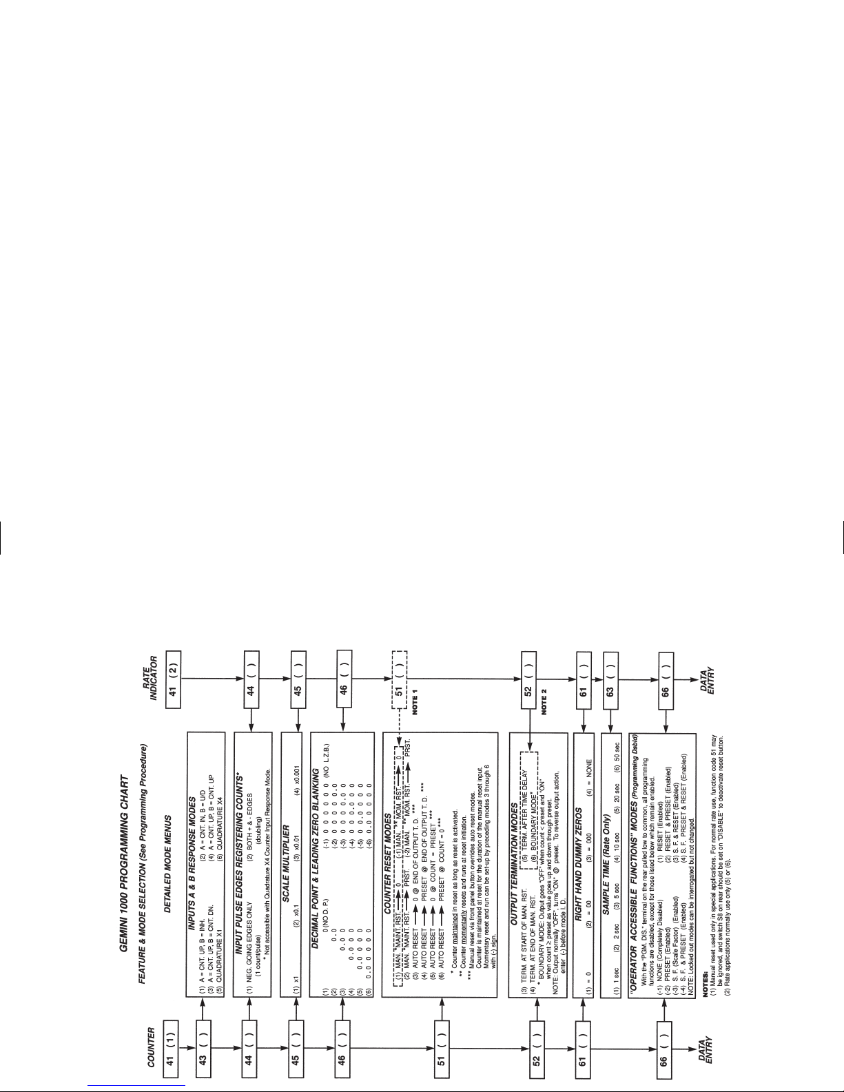
APPENDIX “F” - GEMINI 1000 PROGRAMMING CHART CARD
Page 54

APPENDIX “F” - GEMINI 1000 PROGRAMMING CHART CARD
Page 55

APPENDIX “F” - GEMINI 2000 PROGRAMMING CHART CARD
Page 56

APPENDIX “F” - GEMINI 2000 PROGRAMMING CHART CARD
Page 57

APPENDIX “G” - ORDERING INFORMATION
MODEL NO. DESCRIPTION OPTIONS PART NUMBERS
W/Relay Board W/20 mA Current Loop 115/230 VAC
GEM1 Gemini 1000 Yes No GEM10060
GEM2 Gemini 2000 Yes No GEM20060
Yes Yes GEM20160
¾
Gemini 1000 Relay Board RLYBD000
¾
Gemini 2000 Relay Board RLYBD002
For InformationonPricing,Enclosures,BaseMountKits,&PanelAdapterKits,refertothe Red Lion Controls Catalog or contact your
local RLC distributor.
Page 58

This page is intentionally left blank.
Page 59

LIMITED WARRANTY
The Company warrants the products it manufactures against defects in
materials and workmanship for a period limited to one year from the date of
shipment, provided the products have been stored, handled, installed, and used
under proper conditions. The Company’s liability under this limited warranty
shall extend only to the repair or replacement of a defective product, at The
Company’s option. The Company disclaims all liability for any affirmation,
promise or representation with respect to the products.
The customer agrees to hold Red Lion Controls harmless from, defend, and
indemnify RLC against damages, claims, and expenses arising out of
subsequent sales of RLC products or products containing components
manufactured by RLC and based upon personal injuries, deaths, property
damage, lost profits, and other matters which Buyer, its employees, or subcontractors are or may be to any extent liable, including without limitation
penalties imposed by the Consumer Product Safety Act (P.L. 92-573) and
liability imposed upon any person pursuant to the Magnuson-Moss Warranty
Act (P.L. 93-637), as now in effect or as amended hereafter.
No warranties expressed or implied are created with respect to The Company’s
products except those expressly contained herein. The Customer acknowledges
the disclaimers and limitations contained and relies on no other warranties or
affirmations.
GEM1&2CVR.QXD 4/10/02 11:04 AM Page 3
Page 60

GEM2 / IM - L 4/02
DRAWING NO. LP0098
Red Lion Controls
20 Willow Springs Circle
York PA 17402
Tel +1 (717) 767-6511
Fax +1 (717) 764-0839
Red Lion Controls BV
Databankweg 6C
NL - 3821 AL Amersfoort
Tel +31 (33) 472 32 25
Fax +31 (33) 489 37 93
Red Lion Controls France
56 Boulevard du Courcerin, Batiment 21,
ZI Pariest F-77183 Croissy Beaubourg
Tel +33 (64) 80 12 12
Fax +33 (64) 80 12 13
GEM1&2CVR.QXD 4/10/02 11:04 AM Page 4
 Loading...