

Page 1
Bulletin No. G3USB-X
Drawing No. LP0844
Effective 08/11
Tel +1 (717) 767-6511
Fax +1 (717) 764-0839
www.redlion.net
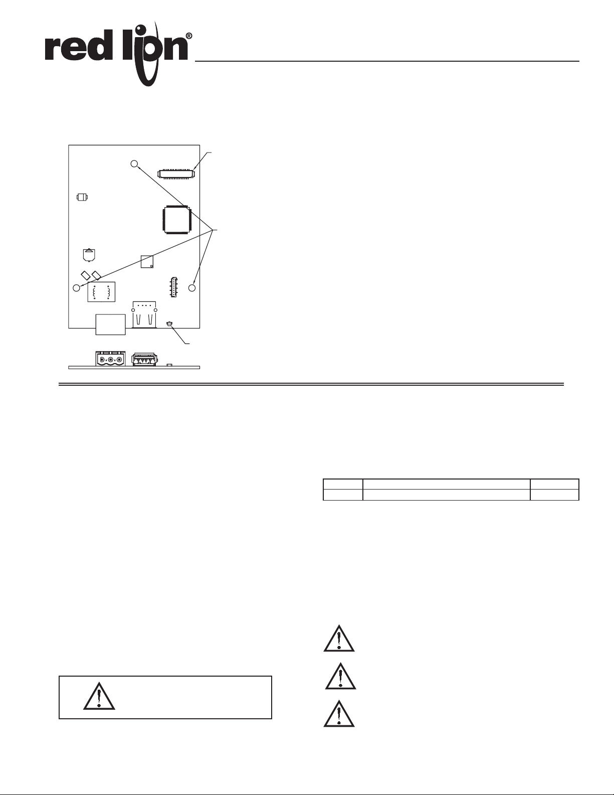
MODEL G3USB - USB HOST OPTION CARD FOR THE G306A OPERATOR
INTERFACE TERMINAL
CONNECTOR
(SIDE 2)
CONFIGURED USING CRIMSON® 3.0 (OR LATER) SOFTWARE
MOUNTING HOLES
(3 PLACES)
INSTALLS INSIDE A G306A OPERATOR INTERFACE TERMINAL
INSTALLATION AND CONNECTION HARDWARE INCLUDED
WITH CARD
POWER USB
STATUS LED
GENERAL DESCRIPTION
The G3 proprietary expansion slot provides a high speed parallel architecture
that extends the functionality and flexibility of the G3 series HMI. This
approach allows the G3 series to evolve concurrently with the latest advances in
communications and standards without sacrificing performance. This high
bandwidth channel has significantly greater throughput when compared to the
traditional (external) serial gateway approach.
The G3USB option card is easily installed by removing the rear cover of your
G3 operator interface, attaching the card using the supplied screws and
connecting a single cable. Installing this card adds a USB host port to the G306A
HMI that is not available on standard units.
Having an on-board USB host port will allow such functionality as file
transfer from CompactFlash to USB memory stick or attachment of peripherals
such as a keyboard or bar code reader.
SAFETY SUMMARY
All safety related regulations, local codes and instructions that appear in the
literature or on equipment must be observed to ensure personal safety and to
prevent damage to either the instrument or equipment connected to it. If
equipment is used in a manner not specified by the manufacturer, the protection
provided by the equipment may be impaired.
Do not use the controller to directly command motors, valves, or other
actuators not equipped with safeguards. To do so can be potentially harmful to
persons or equipment in the event of a fault to the controller.
CONTENTS OF PACKAGE
- G3USB Host Option Card
- Cable already attached to option card
- Hardware pack consisting of three screws.
- This hardware bulletin
ORDERING INFORMATION
MODEL NO. DESCRIPTION PART NUMBER
G3USB USB Host Option Card for G306A operator interface G3USBHC0
THIS EQUIPMENT IS SUITABLE FOR USE IN CLASS I,
DIVISION 2, GROUPS A, B, C, D, HAZARDOUS LOCATIONS,
OR NON-HAZARDOUS LOCATIONS ONLY
CAUTION: Risk of Danger.
Read complete instructions prior to
installation and operation of the unit.
WARNING - EXPLOSION HAZARD - DO NOT DISCONNECT
EQUIPMENT WHILE THE CIRCUIT IS LIVE OR UNLESS THE AREA
IS KNOWN TO BE FREE OF IGNITABLE CONCENTRATIONS.
WARNING - EXPLOSION HAZARD - SUBSTITUTION OF ANY
COMPONENT MAY IMPAIR SUITABILITY FOR CLASS I,
DIVISION 2
1
Page 2
speCIfICatIOns
1. POWER REQUIREMENTS:
24VDC ± 20%; 0.25A max; 0.25A typical (independent from the host G3
power connection). Must use NEC Class 2 or Limited Power Source (LPS)
rated power supply.
2. ENVIRONMENTAL CONDITIONS:
Operating Temperature Range: 0 to 50 °C
Storage Temperature Range: -20 to 80 °C
Operating and Storage Humidity: 80% maximum relative humidity (non-
condensing) from 0 to 50 °C.
Altitude: Up to 2000 meters.
3. USB HOST PORT:
Complies with universal serial bus specification Rev 2.0. Support data
transfers at full-speed. Hardware over-current protected (0.5 A max).
4. CERTIFICATIONS AND COMPLIANCES:
SAFETY:
IEC 61010-1, EN 61010-1: Safety requirements for electrical equipment for
measurement, control and laboratory use, Part 1.
ELECTROMAGNETIC COMPATIBILITY
Emissions and Immunity to EN 61326: Electrical Equipment for Measurement,
Control and Laboratory use.
Immunity to Industrial Locations: Reference G3 unit for immunity
specifications
Emissions:
Emissions EN 55011 Class A
Note:
1. The G3USB option card has been tested and found to comply with the
limits for a Class A digital device, pursuant to part 15 of the FCC rules.
5. CONSTRUCTION: Installation Category I, Pollution Degree 2.
6. INSTALLATION REQUIREMENTS: Card must be installed inside the
rear cover of a G3 operator interface with the hardware provided. See
“Installing the G3USB Option Card” for more details.
7. WEIGHT: 1.6 oz (45.36 g)
InstallIng the g3UsB OptIOn Card
INSTALLATION INSTRUCTIONS
Caution: The option and main circuit boards contain static
sensitive components. Before handling the cards, discharge
static charges from your body by touching a grounded bare
metal object. Ideally, handle the cards at a static controlled clean
workstation. Also, handle the cards by the edges only. Dirt, oil,
or other contaminants that may contact the cards can adversely
affect circuit operation.
Warning: Depending upon the G3 operator interface, high voltage
may be present inside the operator interface. Be sure to remove
all power before removing the rear cover of the operator interface.
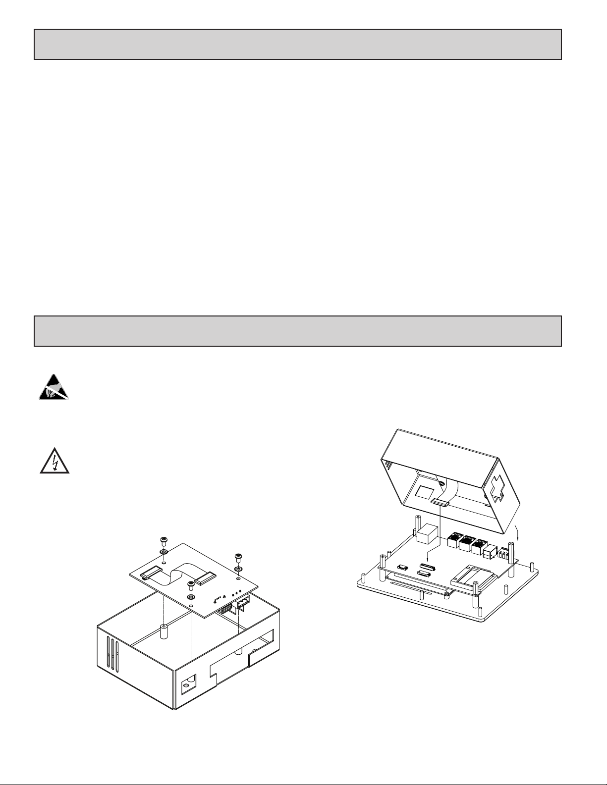
Each G3USB option card comes with a cable for communications from the
main G3 operator interface PC board. It also comes with three screws for
attaching the option card to the inside of the G3 operator interface’s rear cover.
Figure 1
To install the option card remove all power and communication cables from
the unit. The chassis ground connection to the rear cover may be left connected.
The G3 operator interface literature contains instructions for removing the rear
cover, refer to the “Battery & Time Keeping” section.
Using the three screws provided connect the option card to the rear cover as
shown in Figure 1.
Figure 2
Connect the cable from the option card to CN11 on the main board of the G3
operator interface as shown in Figure 2. Be sure both ends of the cables are
firmly seated into their appropriate connector housing.
Carefully replace the rear cover by reversing the previous instructions for
removing the rear cover.
2
Page 3

THE OPTION CARD LABEL
Place the option card label on your rear cover in the space indicated by the
dashed lines and labeled “COMMS EXPANSION MODULE.”
RS232
COMMS EXPANSION MODULE
RS485
RS232
POWER SUPPLY REQUIREMENTS
NEW AND EXISTING INSTALLATIONS
The G3USB option card needs 24 V power independently of the G3. Wires
should be jumpered from the 24 V main supply of the G3 to the option card. The
power connections described above are absolutely essential to prevent any
ground loops. The 24 V power terminal connector for the G3USB option card is
shown below.
2 24V
1 COMMON
3 CHASSIS
POWER
CONNECTOR
sOftware/UnIt OperatIOn
CRIMSON SOFTWARE
Crimson 3.0 software is available as a free download from www.redlion.net.
LED
The G3USB option card has an LED through the back cover once the option
card is installed. The status of the LED is described in the table below.
LED STATUS
OFF No USB device connected
RED Device connected, NOT configured
GREEN Device configured
CONFIGURING A G3USB OPTION CARD
free download from www.redlion.net/g3, or it can be ordered on CD. Updates to
Crimson for new features and drivers are posted on the website as they become
available. By configuring the G3USB using the latest version of Crimson, you
are assured that your unit has the most up to date feature set. Crimson software
can configure the G3USB through the RS232 PGM port, Ethernet port,
CompactFlash socket or through the USB host port itself on your G306A
operator interface. Additional information can be found in your G306A operator
interface hardware literature and the Crimson user manual.
TROUBLESHOOTING YOUR G3USB
OPTION CARD
questions concerning your new G3USB option card, contact Red Lion’s
technical support. For contact information, refer to the back page of this bulletin
for phone and fax numbers.
The G3USB is configured using Crimson software. Crimson is available as a
If for any reason you have trouble operating, connecting, or simply have
EMAIL: techsupport@redlion.net
Web Site: http://www.redlion.net
3
Page 4

The Company warrants the products it manufactures against defects in materials and workmanship
LIMITED WARRANTY
for a period limited to two years from the date of shipment, provided the products have been stored,
handled, installed, and used under proper conditions. The Company’s liability under this limited
warranty shall extend only to the repair or replacement of a defective product, at The Company’s
option. The Company disclaims all liability for any affirmation, promise or representation with
respect to the products.
The customer agrees to hold Red Lion Controls harmless from, defend, and indemnify RLC against
damages, claims, and expenses arising out of subsequent sales of RLC products or products
containing components manufactured by RLC and based upon personal injuries, deaths, property
damage, lost profits, and other matters which Buyer, its employees, or sub-contractors are or may be
to any extent liable, including without limitation penalties imposed by the Consumer Product Safety
Act (P.L. 92-573) and liability imposed upon any person pursuant to the Magnuson-Moss Warranty
Act (P.L. 93-637), as now in effect or as amended hereafter.
No warranties expressed or implied are created with respect to The Company’s products except those
expressly contained herein. The Customer acknowledges the disclaimers and limitations contained
herein and relies on no other warranties or affirmations.
Red Lion Controls
Headquarters
20 Willow Springs Circle
York PA 17406
Tel +1 (717) 767-6511
Fax +1 (717) 764-0839
Red Lion Controls
Europe
Printerweg 10
NL - 3821 AD Amersfoort
Tel +31 (0) 334 723 225
Fax +31 (0) 334 893 793
Red Lion Controls
India
54, Vishvas Tenement
GST Road, New Ranip,
Ahmedabad-382480 Gujarat, India
Tel +91 987 954 0503
Fax +91 79 275 31 350
Red Lion Controls
China
Unit 101, XinAn Plaza
Building 13, No.99 Tianzhou Road
ShangHai, P.R. China 200223
Tel +86 21 6113-3688
Fax +86 21 6113-3683
 Loading...