

Page 1
IDEAL FOR PORTABLE, MOBILE, OR STATIONARY INDUSTRIAL
APPLICATIONS
AVAILABLE IN TWO VERSIONS:
FRONT PANEL RESET OR REMOTE RESET
LOW COST/HIGH PERFORMANCE
OPERATES FROM SWITCH CONTACT OR NPN OPEN
COLLECTOR INPUTS
PROVIDES YEARS OF SILENT OPERATION WITHOUT
MECHANICAL WEAR
SELF POWERED, 2-WIRE CONNECTION, ELIMINATES
POWER WIRING
EASY SNAP-IN MOUNTING IN 1" X 2" (25 mm x 50 mm)
PANEL OPENING
MODEL CUB 3 & CUB3R - GENERAL PURPOSE, MINIATURE ELECTRONIC COUNTERS
ECONOMICAL REPLACEMENT FOR ELECTRO-MECHANICAL COUNTERS
DESCRIPTION
The CUB3s are miniature electronic counters. The CUB3 has front panel
reset, while the CUB3R has remote reset. These units fill a wide variety of
applications.
The CUB3s feature a rugged reinforced nylon case that snap-fits into a
standard rectangular opening without screws or other hardware. Hook-up is
simply a matter of connecting two wires, and since the operating voltage is only
3 V and with currents in microamps, almost any kind of wire can be used. No
external power is required since the internal batteries provide years of
uninterruptible service. In addition to these advantages, the CUB 3’s offer the
inherent ruggedness, reliability, and permanence of completely integrated
circuitry, embedded in a single monolithic, silicon, micro-chip.
SAFETY SUMMARY
All safety related regulations, local codes and instructions that appear in the
manual or on equipment must be observed to ensure personal safety and to
prevent damage to either the instrument or equipment connected to it. If
equipment is used in a manner not specified by the manufacturer, the protection
provided by the equipment may be impaired.
SPECIFICATIONS
1. DISPLAY: 6-Digit, LCD, 0.2" (5.1 mm) High.
2. POWER: 3 Volts supplied by 2 replaceable Alkaline “N” Cells. Nominal
battery life 4 years. Battery life is dependent upon usage. Count and reset
contacts that remain closed for long periods of time reduce battery life.
3. RESET:
CUB 3 - Via front panel reset button only.
CUB 3R - (Remote Reset Only) Switch Contact or Solid State Transistor
Switch (See Connections). Contact burden 14 µA; Max. OFF-State
leakage current must be less than 2 µA. Counter resets with negative pulse
with a min. pulse width of 5 msec.
4. COUNT INPUT: Switch Contact or Solid-State Transistor Switch (See
Connections). Contact burden 14 µA; Max. OFF-State leakage current must
be less than 2 µA. Counter increments on negative going edge of input.
5. COUNT SPEED: 100 counts/sec (6000 counts/min). Min. input pulse width
5 msec, with 5 msec spacing between count pulses.
6. ENVIRONMENTALCONDITIONS:
Operating Temperature: -30° to +75°C
Storage Temperature: -40° to +80°C
Vibration According to IEC 68-2-6: Operational 5 to 500 Hz, in X, Y, Z
direction for 1.5 hours, 5g’s.
Shock According to IEC 68-2-27: Operational 30 g, 11 msec in 3 directions.
Operating and Storage Humidity: 85% max. relative humidity (non-
condensing) from 0°C to 50°C.
Altitude: Up to 2000 meters
7. CERTIFICA TIONS AND COMPLIANCES:
SAFETY
IEC 1010-1, EN 61010-1: Safety requirements for electrical equipment for
measurement, control, and laboratory use, Part 1.
ELECTROMAGNETIC COMPATIBILITY
Note:
Refer to the EMC Installation Guidelines section of this bulletin for additional
information.
8. CONSTRUCTION: Installation Category I, Pollution Degree 2
9. WEIGHT: 3 oz. (85 g) [Less Batteries]
Level 3; 10 V/mENV 50204
200 Hz, 50% duty cycle
900 MHz, ±5 MHz
Immunity to EN 50082-2
Electrostatic discharge EN 61000-4-2 Level 2; 4 Kv contact
Emissions to EN 50081-2
Level 3; 8 Kv air
Electromagnetic RF fields EN 61000-4-3 Level 3; 10 V/m
80 MHz - 1 GHz
Fast transients (burst) EN 61000-4-4 Level 4; 2 Kv I/O
Level 3; 2 Kv power
RF conducted interference EN 61000-4-6 Level 3; 10 V/rms
150 KHz - 80 MHz
Power frequency magnetic fields EN 61000-4-8 Level 4; 30 A/m
RF interference EN 55011 Enclosure class A
Power mains class A
CAUTION: Read complete instructions prior to
installation and operation of the unit.
ORDERING INFORMATION
Bulletin No. CUB3/R-F
Drawing No. LP0126
Released 02/09
Tel +1 (717) 767-6511
Fax +1 (717) 764-0839
www.redlion.net
Simulation of cordless telephones
BNA00001
Note: Batteries not supplied with counter, order separately.
1.5 V Alkaline “N” Cells (2 Req’d)BNA
CUB3R000CUB3 (Remote Reset Only)CUB3R
CUB30000CUB3 (Front Panel Reset Only)CUB3
PART NUMBERSDESCRIPTIONMODEL NO.
Page 2
Installation Environment
The unit should be installed in a location that does not exceed the maximum
operating temperature and provides good air circulation. Placing the unit near
devices that generate excessive heat should be avoided.
The bezel should be cleaned only with a soft cloth and neutral soap product.
Do NOT use solvents. Continuous exposure to direct sunlight may accelerate
the aging process of the bezel.
Do not use tools of any kind (screwdrivers, pens, pencils, etc.) to operate the
keypad of the unit.
EMC INSTALLATION GUIDELINES
Although this unit is designed with a high degree of immunity to
ElectroMagnetic Interference (EMI), proper installation and wiring methods
must be followed to ensure compatibility in each application. The type of the
electrical noise, source or coupling method into the unit may be different for
various installations. Listed below are some additional EMC guidelines for
successful installation in an industrial environment.
1. Use shielded (screened) cables for all Signal and Control inputs. The shield
(screen) pigtail connection should be made as short as possible. The
connection point for the shield depends somewhat upon the application.
Listed below are the recommended methods of connecting the shield, in
order of their effectiveness.
a. Connect the shield only at the panel where the unit is mounted to earth
ground (protective earth).
b. Connect the shield to earth ground at both ends of the cable, usually when
the noise source frequency is above 1 MHz.
c. Connect the shield to common of the unit and leave the other end of the
shield unconnected and insulated from earth ground.
2. Never run Signal or Control cables in the same conduit or raceway with AC
power lines, conductors feeding motors, solenoids, SCR controls, and
heaters, etc. The cables should be run in metal conduit that is properly
grounded. This is especially useful in applications where cable runs are long
and portable two-way radios are used in close proximity or if the installation
is near a commercial radio transmitter.
3. Signal or Control cables within an enclosure should be routed as far away as
possible from contactors, control relays, transformers, and other noisy
components.
4. In extremely high EMI environments, the use of external EMI suppression
devices, such as ferrite suppression cores, is effective. Install them on Signal
and Control cables as close to the unit as possible. Loop the cable through the
core several times or use multiple cores on each cable for additional protection.
The following EMI suppression devices (or equivalent) are recommended:
Ferrite Suppression Cores for signal and control cables:
Fair-Rite # 0443167251 (RLC #FCOR0000)
TDK # ZCAT3035-1330A
Steward #28B2029-0A0
5. Long cable runs are more susceptible to EMI pickup than short cable runs.
Therefore, keep cable runs as short as possible.
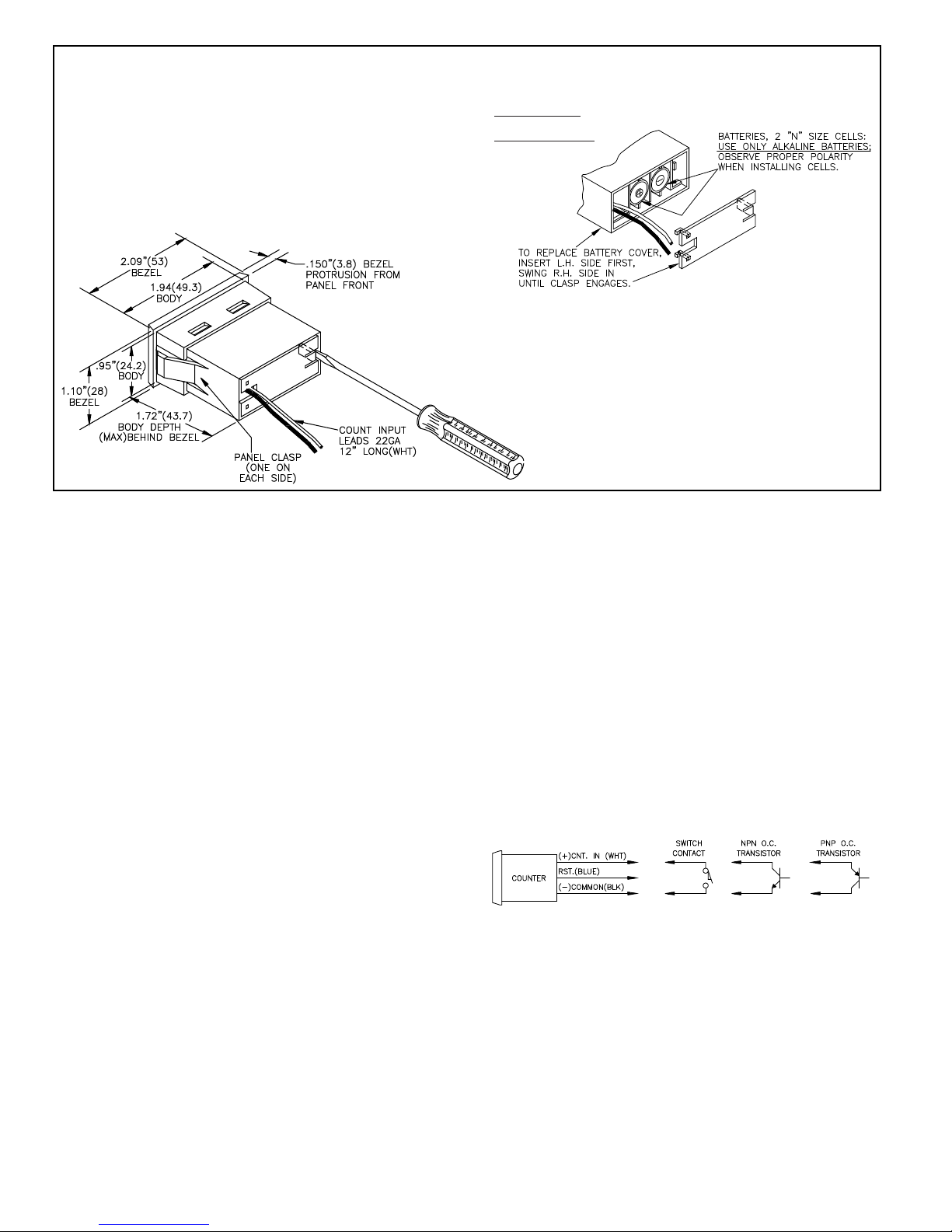
ELECTRICAL CONNECTIONS & COUNT INPUTS
The CUB 3s can be supplied with count input signals from mechanical
switch contacts or solid-state switches (NPN or PNP transistors) as shown in
the diagrams below. Reed switches, mercury-wetted contacts, snap-action limit
switches, and silver alloy contacts with wiping action are usually satisfactory
choices for mechanical switch input. Heavy “clapper-type” contacts such as
used in contactors or large machine tool relays, tungsten contacts, or brush type
contacts are not recommended as count input devices.
DIMENSIONS In inches (mm), INSTALLATION & BATTERY INSERTION
TO REMOVE REAR BATTERY COVER
INSERT BLADE OF SMALLSCREWDRIVER
IN R.H. OPENING AND SWING HANDLE
SLIGHTLYTO THE RIGHT TO DEFLECT
INTERNAL CLASP. RIGHT HAND SIDE OF
COVER WILL NOW SWING OUT.
P
ANEL
CUT
-OUT
1" x 2" or 25 MM x 50 MM
P
ANEL THICKNESS
0.05" to 0.125"
TROUBLESHOOTING
For further technical assistance, contact technical support at the appropriate company
numbers listed.
Red Lion Controls
Headquarters
20 Willow Springs Circle
York PA 17406
Tel +1 (717) 767-6511
Fax +1 (717) 764-0839
Red Lion Controls
China
Unit 101, XinAn Plaza
Building 13, No.99 Tianzhou Road
ShangHai, P.R. China 200223
Tel +86 21 6113-3688
Fax +86 21 6113-3683
Red Lion Controls
Europe
Printerweg 10
NL - 3821 AD Amersfoort
Tel +31 (0) 334 723 225
Fax +31 (0) 334 893 793
Red Lion Controls
India
54, Vishvas Tenement
GST Road, New Ranip,
Ahmedabad-382480 Gujarat, India
Tel +91 987 954 0503
Fax +91 79 275 31 350
 Loading...