

Bulletin No. CUB1/2-K
Drawing No. LP0001
Released 07/14
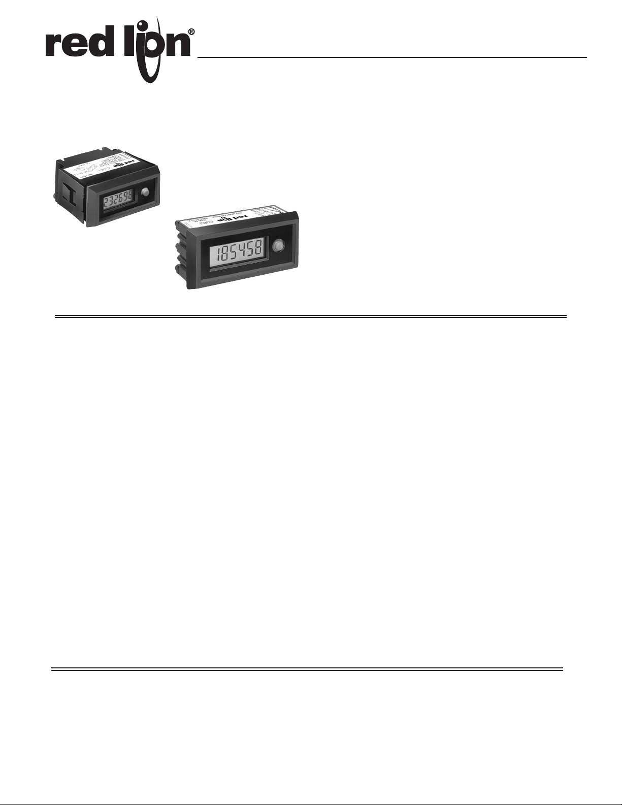
MODELS CUB 1 & CUB 2 - MINIATURE ELECTRONIC 6-DIGIT COUNTER
CUB 1 MINIATURE
ELECTRONIC COUNTER
CUB 2 GENERAL PURPOSE
INDUSTRIAL COUNTER
GENERAL DESCRIPTION
SELF POWERED
Self-Contained batteries eliminate the need for external power and prevent
loss of count if power fails. Also provides for remote or portable applications.
Battery operation also means elimination of shock hazard and allows the use of
2-conductor bell wire for count signals and micro-power input signals.
Batteries are easily replaceable (2 “N” Cells, alkaline) and average battery
life is four years.
FLEXIBILITY
Various count inputs allow use with switch contacts or high speed pulse
outputs from electronic sensors and circuits. The reset function can be disabled,
set up for front panel reset, remote reset, or both.
NO-WEAR, NO-NOISE
The CUB’s micro-circuits can accurately and silently accumulate enough
counts in one hour to completely wear out an ordinary E.M. counter. More over,
it can repeat this performance many times with just one set of batteries.
RELIABILITY
Internal “micro-assembly” construction withstands many times the “g” force
of shock and vibration compared to conventional construction.
CUB counters also feature elastomeric contacts. This eliminates long term
problems associated with contact corrosion.
Battery operation, a high degree of input filtering, plus an inherent common
mode rejection ratio of more than 120 dB @ 50/60 Hz, provides ultra-high
immunity from electrical noise interference.
ACCEPTS HIGH SPEED PULSES FROM TTL, CMOS, OR OTHER
ELECTRONIC SOURCES
PRICED LESS THAN EQUIVALENT
E.M.[ELECTRO-MECHANICAL] COUNTERS
RUGGED CONSTRUCTION
SPECIFICATIONS
1. DISPLAY: 6-digit LCD
CUB 1: 0.2" (5 mm) high
CUB 2: 0.35" (9 mm) high
2. POWER SOURCE: No external power required. Operates from 2 “N” type
alkaline batteries (supplied separately). Battery life up to 4 years. (See Note
below.)
3. COUNT & RESET INPUT SIGNALS: Adapts to Count-Switch Contact
Signals, Open-Collector Transistor Outputs, and Bi-Polar Drive Outputs as
shown in the diagrams on the following page. Counter increments and resets
on negative going (pull down) transition of count or reset signal.
4. ENVIRONMENTAL CONDITIONS:
Storage Temperature Range: -20° to 60°C (-4° to 140°F)
Operating Temperature Range: 0° to 50°C (32° to 122°F)
Vibration to IEC 68-2-6: Operational 5 to 500 Hz, 5 g.
Shock to IEC 68-2-27: Operational 30 g.
5. COUNT SPEED: Up to 50 Hz with switch contact input (counters have
internal de-bounce circuits) or up to 5 KHz with solid-state electronic input
(See diagrams on following page).
6. CONSTRUCTION: Rugged die-cast metal case with clear viewing window.
The sealed front panel meets NEMA 4X/IP65 requirements when properly
installed. Panel gasket and mounting clips included.
7. WEIGHT:
CUB 1: 4.0 oz (113.4 g)
CUB 2: 5.2 oz (147.4 g)
Note: When using switch contacts for count input or remote reset, normally
open contact circuits are recommended. Switch contacts that remain
normally-closed and are opened only briefly to signal a count, can reduce
battery life to somewhat less than 4 years.
USE CUB COUNTERS WITH:
VCM • VOLTAGE CONVERTER MODULES for isolated, A.C., control voltage count inputs to 270 VAC,
LCM • LOGIC CONVERTER MODULES for interface with standard logic voltages & outputs
1
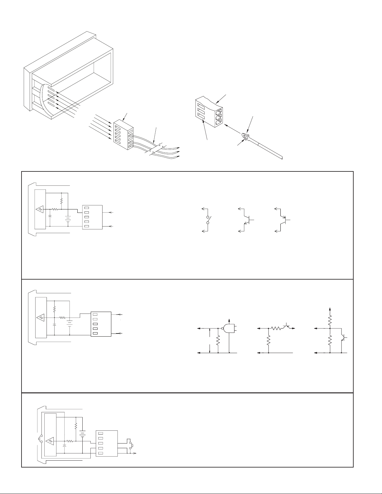
APPLICATION FLEXIBILITY VIA RECONNECT OPTIONS
COMMON
COMMON
COMMON
SWITCH
NPN
PNP
Selection of desired operating modes is easily done by adding or moving
terminal leads in the Input Connector Body. The connector body is polarized to
prevent incorrect insertion, and locked in place by the battery cover to avoid
accidental disengagement. Connectors are supplied with the 3 leads installed as
shown below. A spare blue lead is supplied in the hardware pack.
TO REMOVE TERMINAL, insert blade of a small screwdriver into slot of
connector body, and gently push in to disengage lock pawl. Pull terminal out.
WHEN INSERTING TERMINAL into connector body, make sure the lock
pawl is toward the slot in the body. Push terminal in until lock pawl snaps
into slot.
CONNECTOR
BODY
H.S. CNT.
L.S. CNT.
REM. RST.
RST. EN.
COMMON
CONNECTOR
BODY
WHT
YELL
BLK
22GA STANDARD
WIRE 10" LONG
LOCK PAWL
ENGAGES IN SLOT
CONNECTOR
TERMINAL
LOW SPEED COUNT INPUT, 50 Hz MAX. [For 250 Hz see note in text]
+3V
µ
CHIP
COMM.
CONTACT
INPUT
300K
1M
C
4700pf
BATT.
3.0V
H.S. CNT.
L.S. CNT.
REM. RST.
RST. EN.
COMMON
WHT
BLK
L.S. CNT.
O.C. TRANSISTOR
OR (N) FET
INPUT
L.S. CNT.
O.C. TRANSISTOR
OR (P) FET
INPUT
L.S. CNT.
Pulling the L.S. CNT. Input to Common with a mechanical or solid-state
switch increments the counter. The low pass filter (1meg resistor and 4700
pf cap) used with a Schmidt trigger circuit debounces mechanical switch
signals. The switch load is 14 µA (max. voltage drop 0.5 V) when ON. OFF-
state leakage current must be less than 2 µA.
HIGH SPEED COUNT INPUT, 5 KHz MAX.
+3V
µ
CHIP
COMM.
1.3M
10K
C
4700pf
BATT.
3.0V
H.S. CNT.
L.S. CNT.
REM. RST.
RST. EN.
COMMON
WHT
BLK
Moving the white wire to the H.S. CNT. Input allows the CUB Counter to
operate at speeds up to 5 KHz when driven by bi-polar outputs or external
circuits having an output impedance of 3.3 KΩ or less. Input drive voltage
must be limited to 3.0 V maximum to avoid a charging current into the
batteries which can cause premature battery failure or leakage. CMOS and
TTL Logic outputs can be loaded with a resistor (Rl) to limit drive voltage,
or a voltage divider can be used as shown for the PNP O.C. Transistor output.
RESET OPTIONS
+3V
FRONT
PANEL
RESET
COMM.
CHIP
µ
220K
BATT.
H.S. CNT.
3.0V
1M
R
4700pf
L.S. CNT.
REM. RST.
RST. EN.
COMMON
BLUE
YEL
BLK
REMOTE
RESET
TO COUNT
SIGNAL
COMMON
Reed switches, mercury wetted contacts, snap action limit switches, and
silver alloy relay contacts with wiping action are usually satisfactory for
generating count input signals. Motor starter contacts, tungsten contacts, and
brush-type contacts should NOT be used.
Note: By parallel connecting both H.S. CNT. and L.S. CNT. inputs, count
speed can be increased to 250 Hz if de-bounce is not needed.
TTL OR CMOS PNP O.C. TRANSISTOR NPN
OUTPUT OR BI-POLAR OUTPUT O.C. TRANSISTOR
+V
H.S. CNT
COM
3.0 V
MAX.
R
SEE
TEXT
+5 VDC
L
H.S. CNT
COM
3.3 K
R
H.S. CNT
+V
COM
R
3.3 K
INPUT PULSE EXCURSION LIMITS
Vin (High) = +2.7 V min. +3.3 V max.
Vil (Low) = +0.5 V max.
Connecting the RST. EN. (Reset Enable) Input to Common activates the
front panel Reset button. When the front panel Reset button is to be
de-activated, remove the yellow wire from the RST. EN. Input.
When Remote Reset is required, the blue wire in the hardware pack is
inserted in the REM. RST. Input. Pulling this input low causes the counter to
reset. The REM. RST. can be pulled low by either a mechanical switch or
solid-state transistor switch. Switch load and leakage are the same as for L.S.
CNT. Input above.
Note: The RC protection circuit on the REM. RST. Input causes a delay of
approximately 6 msec in Reset response.
2

DIMENSIONS, INSTALLATION, & BATTERY INSERTION
.26"
MOUNTING
1.415"
After cutting opening in panel, slide the panel gasket over the rear of the
counter body to the back of the bezel. Then slide counter through the panel cutout. Install mounting clips on each side of counter body with mounting screws.
the counter body so that the “Tang Ends” or “Tabs” wedge between the panel
opening and body as the screws are tightened.
Make sure the side rails or tabs of the clips fit into the recesses in the side of
CUB 1
(6.6)
EXISTING PANEL
.05" TO .20" THICK
(1.3 TO 5.1 mm THICK)
PANEL CUT OUT
.87"X 1.77"
(22.2 X 45mm)
MOUNTING
CLIPS
TAB
SCREWS
(36)
.945"
(24)
1.89"
(48)
UPPER
CLASP
LOWER
CLASP
1.81"
(46)
GASKET
.032"(0.8)
THICK
BATTERY
COVER
TAB
DIMENSIONS In inches (mm)
BATTERY COVER REMOVAL & BATTERY INSERTION
CUB 1
The battery cover is held in place by upper and lower clasps that capture
mating lock ramps on the cover. To remove, insert thumbnail and index finger
nail in the gaps between the upper and lower clasps and the battery cover, and
deflect the clasps slightly to clear the edges of the ramps while pulling out on
the cover. To replace cover, simply push into place until both clasps snap into
engagement with lock ramps.
CAUTION: Do not deflect clasps more than necessary to clear lock ramps.
Excessive deflection can cause clasps to break off.
CUB 2
2.835"
(72)
BATTERY
COVER
GASKET
.032"(0.8)THICK
.325"
(8.3)
SLIDE
TO OPEN
0.95"
(24.1)
TANG
ENDS
EXISTING PANEL
.05" TO .20" THICK
(1.3 TO 5.1mm THICK)
PANEL CUT-OUT
1.3"X 2.65"
(33X 67.3mm)
MOUNTING
CLIPS
MOUNTING
SCREWS
CUB 2
Slide battery cover to the left until the right hand lip disengages and pops
out. To reinstall cover, insert left hand lips into case first, push cover to the left
until right hand lip drops down and cover snaps back into place. Install
batteries as shown below observing proper polarity.
Note: Push battery spring clips to the left (toward connector) to completely
free the batteries when removing or installing batteries. Conductive
rubber battery contacts can be torn from their retaining pins if batteries
are forced in.
BATTERIES SHOWN IN
+
INPUT CONNECTOR
-
PLACE: CENTER (+)
OUT, RIGHT (-) OUT.
ELECTRICAL CONNECTIONS
There are certain considerations that shoud be observed when running the
count and control signal wires. A length of wire can act like an antenna and the
closer it is to a source of electrical noise, the more it becomes susceptible to
that noise.
There are a few rules that should be followed when running these wires.
1. Never run count or control signal wires in the same conduit or raceway with
AC power lines, conductors that feed motors, solenoids, SCR controls,
heaters, etc.
ORDERING INFORMATION
MODEL NO. PART NUMBERS
CUB 1 CUB 1 Miniature Electronic Counter CUB10000
CUB 2 CUB20000
BNA BNA00001
HWK 1 CUB 1 Spare Hardware Kit (Note 2) HWK10000
HWK 2 CUB 2 Spare Hardware Kit (Note 2) HWK20000
For more information on Pricing, Enclosures & Panel Mount Kits refer to the RLC
Catalog or contact your local RLC distributor.
DESCRIPTION
CUB 2 Gen. Purpose Industrial Electronic Counter
“N” Type Alkaline Batteries (Note 1)
ICA ICA00000
Spare Input Connector & Terminal Wires (Note 3)
PUSH CONTACT SPRINGS
-
BATTERY
+
BATTERY
+
-
TOWARD CONNECTOR TO ALLOW
BATTERIES TO DROP IN FREELY.
DO NOT PUSH OR FORCE
BATTERIES INTO PLACE.
2. Signal wires within enclosures should be routed as far away as possible from
contactors, control relays, transformers, and other noisy components.
3. When shielded wire is used, connect the shield to the common of the CUB
unit, and leave the other end of the shield disconnected and insulated from
machine ground.
4. Mount the CUB in a panel that is grounded to the machine frame.
5. When using accessory devices such as LCMs or PSMs into the H.S. CNT.
Input, the accessory devices should be mounted near the CUB Counter.
NOTES
1. Batteries NOT supplied with counters, order separately.
2 required per unit.
2. Counters supplied with required hardware. Includes 2 mounting
clips & screws, panel gasket, 2-wire nuts & blue terminal wire.
3. Counters supplied with connector body & white, yellow, & black
wires. Kit ICA includes connector body & one each of black,
white, blue, & yellow terminal wires.
3

The Company warrants the products it manufactures against defects in materials and workmanship
LIMITED WARRANTY
for a period limited to two years from the date of shipment, provided the products have been stored,
handled, installed, and used under proper conditions. The Company’s liability under this limited
warranty shall extend only to the repair or replacement of a defective product, at The Company’s
option. The Company disclaims all liability for any affirmation, promise or representation with
respect to the products.
The customer agrees to hold Red Lion Controls harmless from, defend, and indemnify RLC against
damages, claims, and expenses arising out of subsequent sales of RLC products or products
containing components manufactured by RLC and based upon personal injuries, deaths, property
damage, lost profits, and other matters which Buyer, its employees, or sub-contractors are or may be
to any extent liable, including without limitation penalties imposed by the Consumer Product Safety
Act (P.L. 92-573) and liability imposed upon any person pursuant to the Magnuson-Moss Warranty
Act (P.L. 93-637), as now in effect or as amended hereafter.
No warranties expressed or implied are created with respect to The Company’s products except
those expressly contained herein. The Customer acknowledges the disclaimers and limitations
contained herein and relies on no other warranties or affirmations.
 Loading...