

Page 1

LP0631
CRIMSON 2
SER MANUAL
U
ODULAR CONTROLLER
M
Page 2

Copyright © 2003-2006 Red Lion Controls.
All Rights Reserved Worldwide.
The information contained herein is provided in good faith, but is subject to change without
notice. It is supplied with no warranty whatsoever, and does not represent a commitment on
the part of Red Lion Controls. Companies, names and data used as examples herein are
fictitious unless otherwise stated. No part of this document may be reproduced or transmitted
in any form or by any means, electronic or mechanical, without the express written
permission of Red Lion Controls.
All trademarks are acknowledged as the property of their respective owners.
Written by Mike Granby and Jesse Benefiel.
Page 3

GETTING STARTED TABLE OF CONTENTS
TABLE OF CONTENTS
GETTING STARTED ........................................................................................... 1
SYSTEM REQUIREMENTS ..................................................................................... 1
INSTALLING THE SOFTWARE................................................................................. 1
CHECKING FOR UPDATES..................................................................................... 1
INSTALLING THE USB DRIVERS ............................................................................ 2
QUICK START .................................................................................................. 3
OVERVIEW ...................................................................................................... 3
MODULES........................................................................................................ 3
COMMUNICATIONS ............................................................................................ 4
MAPPING DATA ................................................................................................ 4
DOWNLOADING ................................................................................................ 7
CONNECT THE TWO ........................................................................................... 8
CRIMSON BASICS............................................................................................. 9
MAIN SCREEN ICONS ......................................................................................... 9
MODULES .......................................................................................................................................9
COMMUNICATIONS ............................................................................................................................9
DATA TAGS................................................................................................................................... 10
USER INTERFACE............................................................................................................................10
PROGRAMMING ..............................................................................................................................10
DATA LOGGER ...............................................................................................................................10
WEB SERVER.................................................................................................................................10
SECURITY MANAGER ....................................................................................................................... 11
SELECTING THE MODULAR CONTROLLER ............................................................... 11
USING BALLOON HELP...................................................................................... 12
WORKING WITH DATABASES .............................................................................. 12
DOWNLOADING TO THE MASTER......................................................................... 12
CONFIGURING THE LINK ...................................................................................................................12
VERIFYING THE USB LINK ................................................................................................................13
SETTING THE IP ADDRESS................................................................................................................ 13
SENDING THE DATABASE ..................................................................................................................13
EXTRACTING DATABASES.................................................................................................................. 14
MOUNTING THE COMPACTFLASH ........................................................................................................14
FORMATTING THE COMPACTFLASH ......................................................................................................15
SENDING THE TIME AND DATE........................................................................................................... 16
UPDATING VIA COMPACTFLASH........................................................................... 16
MODULE CONFIGURATION ............................................................................... 17
WORKING WITH MODULES ................................................................................ 17
INSERTING MODULES ......................................................................................................................17
MOVING MODULES ......................................................................................................................... 17
EDITING MODULES .........................................................................................................................17
CSPID – PID MODULE PROGRAMMING................................................................ 18
THE GENERAL TAB.......................................................................................................................... 18
THE CONTROL TAB .........................................................................................................................20
REVISION 6 PAGE I
Page 4

TABLE OF CONTENTS CRIMSON USER MANUAL - MODULAR CONTROLLER
THE POWER TAB ............................................................................................................................ 22
THE ALARMS TAB ...........................................................................................................................23
THE OUTPUTS TAB .........................................................................................................................26
AUTO-TUNING...............................................................................................................................27
AVAILABLE DATA ............................................................................................................................ 30
CSSG – STRAIN GAGE INPUT PID MODULE PROGRAMMING....................................... 34
THE GENERAL TAB.......................................................................................................................... 34
THE CONTROL TAB .........................................................................................................................36
THE POWER TAB ............................................................................................................................ 38
THE ALARMS TAB ...........................................................................................................................40
THE OUTPUTS TAB .........................................................................................................................42
AUTO-TUNING...............................................................................................................................43
AVAILABLE DATA ............................................................................................................................ 46
CSTC/CSRTD – TEMPERATURE INPUT MODULE PROGRAMMING................................. 51
THE CONFIGURATION TAB ................................................................................................................51
AVAILABLE DATA ............................................................................................................................ 52
CSINI/CSINV – ANALOG INPUT MODULE PROGRAMMING......................................... 53
THE CONFIGURATION TAB ................................................................................................................53
THE LINEARIZATION TAB.................................................................................................................. 54
AVAILABLE DATA ............................................................................................................................ 55
CSOUT – ANALOG OUTPUT MODULE PROGRAMMING............................................... 56
THE CONFIGURATION TAB ................................................................................................................56
THE INITIAL OUTPUT TAB ................................................................................................................57
AVAILABLE DATA ............................................................................................................................ 58
CSDIO – DIGITAL I/O MODULE PROGRAMMING..................................................... 60
THE CONFIGURATION TAB ................................................................................................................60
THE LOGIC EDITOR TAB................................................................................................................... 60
AVAILABLE DATA ............................................................................................................................ 62
CONFIGURING COMMUNICATIONS..................................................................... 65
SERIAL PORT USAGE ........................................................................................ 65
SELECTING A PROTOCOL ................................................................................... 65
PROTOCOL OPTIONS ........................................................................................ 66
WORKING WITH DEVICES .................................................................................. 66
ETHERNET CONFIGURATION ............................................................................... 67
IP PARAMETERS............................................................................................................................. 67
IP ROUTING .................................................................................................................................67
PHYSICAL LAYER ............................................................................................................................67
REMOTE UPDATE............................................................................................................................ 68
PROTOCOL SELECTION..................................................................................................................... 68
MAPPING DATA............................................................................................... 69
MAPPING ITEMS TO A BLOCK............................................................................................................. 70
ACCESSING INDIVIDUAL BITS ............................................................................................................70
READ/WRITE VARIABLES.................................................................................................................. 71
PROTOCOL CONVERSION ................................................................................... 71
MASTER AND SLAVE ........................................................................................................................71
MASTER AND MASTER......................................................................................................................72
WHICH WAY AROUND?....................................................................................................................72
DATA TRANSFORMATION ................................................................................... 72
PAGE II http://www.redlion.net/controller
Page 5

GETTING STARTED TABLE OF CONTENTS
ADVANCED COMMUNICATIONS ......................................................................... 75
USING EXPANSION CARDS ................................................................................. 75
SHARING SERIAL PORTS ................................................................................... 76
ENABLING TCP/IP..........................................................................................................................76
SHARING THE REQUIRED PORT.......................................................................................................... 76
CONNECTING VIA ANOTHER PORT ...................................................................................................... 77
CONNECTING VIA ETHERNET .............................................................................................................77
PURE VIRTUAL PORTS ..................................................................................................................... 78
LIMITATIONS.................................................................................................................................79
USING ELECTRONIC MAIL.................................................................................. 79
CONFIGURING SMTP ......................................................................................................................79
CONFIGURING SMS ........................................................................................................................81
THE ADDRESS BOOK .......................................................................................................................82
WORKING WITH MODEMS ................................................................................. 83
SOME TYPICAL APPLICATIONS ........................................................................................................... 83
ADDING A DIAL-IN CONNECTION........................................................................................................ 84
ADDING A DIAL-OUT CONNECTION .....................................................................................................86
ADDING AN SMS CONNECTION..........................................................................................................87
SMS MESSAGE PROCESSING .............................................................................................................88
USING MULTIPLE INTERFACES ...........................................................................................................88
CHECKING THE MODEM STATUS ......................................................................................................... 89
MODEM INITIALIZATION SEQUENCE ....................................................................................................90
TROUBLESHOOTING MODEM COMMUNICATION ...................................................................................... 91
OPC COMMUNICATION ..................................................................................... 93
OPC SERVER SETTINGS ...................................................................................................................93
OPC AND SCADA .......................................................................................................................... 94
OPC LINK (RED LION PRODUCTS DATA EXCHANGE) ............................................................................... 94
USING TIME MANAGEMENT................................................................................ 95
CONFIGURING THE TIME MANAGER ..................................................................................................... 96
SELECTING AN SNTP SERVER............................................................................................................97
TIME-ZONE CONFIGURATION ............................................................................................................ 98
CONFIGURING THE SYNCHRONIZATION MANAGER (FTP CLIENT) ................................. 98
SYNCHRONIZATION MANAGER SETTINGS .............................................................................................. 98
AUTOMATIC LOG SYNCHRONIZATION ...................................................................................................99
ADVANCED FTP EXCHANGE FUNCTIONS ............................................................................................. 100
CONFIGURING THE FTP SERVER ........................................................................100
FTP SERVER SETTINGS.................................................................................................................. 101
FTP SECURITY ............................................................................................................................ 101
ACCESSING THE SERVER................................................................................................................. 102
CONFIGURING DATA TAGS ............................................................................. 102
ALL ABOUT TAGS ...........................................................................................102
TYPES OF TAGS............................................................................................................................ 102
WHY USE TAGS?.......................................................................................................................... 104
CREATING TAGS ............................................................................................105
EDITING TAGS ..............................................................................................106
EDITING PROPERTIES......................................................................................106
EXPRESSION PROPERTIES ............................................................................................................... 106
TRANSLATABLE STRINGS ................................................................................................................ 107
REVISION 6 PAGE III
Page 6

TABLE OF CONTENTS CRIMSON USER MANUAL - MODULAR CONTROLLER
COLOR PROPERTIES ...................................................................................................................... 108
EDITING FLAG TAGS ...................................................................................... 108
THE DATA TAB (VARIABLES) ........................................................................................................... 109
THE DATA TAB (FORMULAE) ........................................................................................................... 110
THE DATA TAB (ARRAYS)............................................................................................................... 110
THE FORMAT TAB.........................................................................................................................112
THE COLORS TAB ......................................................................................................................... 112
THE ALARMS TAB .........................................................................................................................113
THE TRIGGERS TAB ...................................................................................................................... 114
EDITING INTEGER TAGS .................................................................................. 114
THE DATA TAB (VARIABLES) ........................................................................................................... 115
THE DATA TAB (FORMULAE) ........................................................................................................... 116
THE DATA TAB (ARRAYS)............................................................................................................... 117
THE FORMAT TAB.........................................................................................................................117
THE COLORS TAB ......................................................................................................................... 119
THE ALARM TABS .........................................................................................................................119
THE TRIGGERS TAB ...................................................................................................................... 120
EDITING MULTI TAGS..................................................................................... 121
THE DATA TAB (VARIABLES) ........................................................................................................... 121
THE DATA TAB (FORMULAE) ........................................................................................................... 122
THE DATA TAB (ARRAYS)............................................................................................................... 122
THE FORMAT TAB.........................................................................................................................123
THE COLORS TAB ......................................................................................................................... 124
THE ALARM TABS .........................................................................................................................125
THE TRIGGERS TAB ...................................................................................................................... 125
EDITING REAL TAGS ...................................................................................... 126
EDITING STRING TAGS ................................................................................... 126
THE DATA TAB (VARIABLES) ........................................................................................................... 126
THE DATA TAB (FORMULAE) ........................................................................................................... 127
THE DATA TAB (ARRAYS)............................................................................................................... 127
THE FORMAT TAB.........................................................................................................................128
THE COLORS TAB ......................................................................................................................... 129
MORE THAN TWO ALARMS ............................................................................... 129
VALIDATING TAGS ......................................................................................... 130
EXPORTING TAG MAPPINGS.............................................................................. 130
LOGGING EVENT MESSAGES ............................................................................. 130
NOTES FOR EDICT USERS ................................................................................ 130
CONFIGURING THE MONOCHROME VIRTUAL HMI.............................................. 133
CONTROLLING THE VIEW................................................................................. 133
OTHER VIEW OPTIONS ..................................................................................................................133
USING THE PAGE LIST .................................................................................... 134
DISPLAY EDITOR TOOLBOXES ........................................................................... 134
THE DRAWING TOOLBOX................................................................................................................ 134
THE FILL FORMAT TOOLBOX ........................................................................................................... 134
THE LINE FORMAT TOOLBOX ........................................................................................................... 134
THE TEXT FORMAT TOOLBOX .......................................................................................................... 135
THE FOREGROUND TOOLBOX ........................................................................................................... 135
THE BACKGROUND TOOLBOX........................................................................................................... 135
PAGE IV http://www.redlion.net/controller
Page 7

GETTING STARTED TABLE OF CONTENTS
ADDING DISPLAY PRIMITIVES............................................................................135
SMART ALIGNMENT ....................................................................................................................... 135
KEYBOARD OPTIONS .....................................................................................................................136
LOCK INSERT MODE ...................................................................................................................... 136
SELECTING PRIMITIVES ...................................................................................136
MOVING AND RESIZING ...................................................................................137
REORDERING PRIMITIVES.................................................................................137
EDITING PRIMITIVES.......................................................................................138
PRIMITIVE DESCRIPTIONS ................................................................................138
THE LINE PRIMITIVE ..................................................................................................................... 138
THE SIMPLE GEOMETRIC PRIMITIVES ................................................................................................ 138
THE TANK PRIMITIVES................................................................................................................... 139
THE SIMPLE BAR-GRAPH PRIMITIVES................................................................................................. 139
THE FIXED TEXT PRIMITIVE ............................................................................................................140
THE AUTO TAG PRIMITIVE.............................................................................................................. 141
THE TAG TEXT PRIMITIVES ............................................................................................................. 142
EDITING THE UNDERLYING TAG ....................................................................................................... 144
THE TIME AND DATE PRIMITIVE....................................................................................................... 145
THE RICH BAR-GRAPH PRIMITIVES ................................................................................................... 146
THE SYSTEM PRIMITIVES................................................................................................................ 148
DEFINING PAGE PROPERTIES ............................................................................149
DEFINING SYSTEM ACTIONS .............................................................................150
DEFINING KEY BEHAVIOR.................................................................................150
ENABLING ACTIONS ........................................................................................151
ACTION DESCRIPTIONS....................................................................................151
THE GOTO PAGE ACTION ............................................................................................................... 151
THE PUSH BUTTON ACTION ............................................................................................................152
THE CHANGE INTEGER VALUE ACTION ............................................................................................... 152
THE RAMP INTEGER VALUE ACTION ..................................................................................................153
THE PLAY TUNE ACTION ................................................................................................................ 153
THE USER DEFINED ACTION ........................................................................................................... 154
BLOCK DEFAULT ACTION ................................................................................................................ 154
CHANGING THE LANGUAGE ...............................................................................155
ADVANCED TOPICS .........................................................................................155
ACTION PROCESSING.....................................................................................................................155
DATA AVAILABILITY ...................................................................................................................... 156
CONFIGURING THE COLOR VIRTUAL HMI ........................................................ 157
CONTROLLING THE VIEW .................................................................................157
ZOOM FUNCTION.......................................................................................................................... 157
OTHER VIEW OPTIONS ..................................................................................................................158
USING THE PAGE LIST .....................................................................................158
WORKING WITH THE GRID ...............................................................................159
THE DRAWING TOOLBOX .................................................................................159
ADDING DISPLAY PRIMITIVES............................................................................160
SMART ALIGNMENT ....................................................................................................................... 160
KEYBOARD OPTIONS .....................................................................................................................161
REVISION 6 PAGE V
Page 8

TABLE OF CONTENTS CRIMSON USER MANUAL - MODULAR CONTROLLER
LOCK INSERT MODE ...................................................................................................................... 161
USING THE IMAGE LIBRARY.............................................................................. 161
SELECTING PRIMITIVES................................................................................... 162
MOVING AND RESIZING................................................................................... 162
ALIGNING PRIMITIVES .................................................................................... 163
SPACING PRIMITIVES...................................................................................... 163
REORDERING PRIMITIVES ................................................................................ 163
GROUPING PRIMITIVES ................................................................................... 164
EDITING PRIMITIVES ...................................................................................... 164
DEFINING COLORS......................................................................................... 164
DEFINING FILL PATTERNS................................................................................ 165
DEFINING ACTIONS........................................................................................ 166
ENABLING ACTIONS ....................................................................................... 166
ACTION DESCRIPTIONS................................................................................... 166
THE GOTO PAGE ACTION ............................................................................................................... 167
THE PUSH BUTTON ACTION ............................................................................................................168
THE CHANGE INTEGER VALUE ACTION ............................................................................................... 169
THE RAMP INTEGER VALUE ACTION ..................................................................................................169
THE PLAY TUNE ACTION ................................................................................................................ 170
THE USER DEFINED ACTION ........................................................................................................... 170
USING DEFAULT SETTINGS .............................................................................. 171
PRIMITIVE DESCRIPTIONS................................................................................ 171
THE LINE PRIMITIVE ..................................................................................................................... 171
THE SIMPLE GEOMETRIC PRIMITIVES ................................................................................................ 171
THE TANK PRIMITIVES................................................................................................................... 172
THE SIMPLE BAR PRIMITIVES .......................................................................................................... 172
THE BAR-GRAPH PRIMITIVES .......................................................................................................... 173
THE SCATTER GRAPH PRIMITIVE ......................................................................................................174
THE SCALE PRIMITIVES.................................................................................................................. 177
THE FIXED TEXT PRIMITIVE ............................................................................................................178
THE AUTO TAG PRIMITIVE.............................................................................................................. 180
THE TAG TEXT PRIMITIVES ............................................................................................................. 180
EDITING THE UNDERLYING TAG ....................................................................................................... 183
THE MULTI-LINE TEXT PRIMITIVES...................................................................................................184
THE TIME AND DATE PRIMITIVE....................................................................................................... 184
THE RICH BAR PRIMITIVES ............................................................................................................. 186
THE RICH SLIDER PRIMITIVES .........................................................................................................188
THE ALARM VIEWER PRIMITIVE ....................................................................................................... 190
THE ALARM TICKER PRIMITIVE ........................................................................................................ 195
THE EVENT VIEWER PRIMITIVE ........................................................................................................ 197
THE FILE VIEWER PRIMITIVE........................................................................................................... 197
THE REMOTE DISPLAY PRIMITIVE ..................................................................................................... 198
THE CAMERA PRIMITIVE................................................................................................................. 199
THE TRENDING PRIMITIVES ............................................................................................................ 200
THE GENERAL BUTTON PRIMITIVE ....................................................................................................203
THE RICH BUTTON PRIMITIVE ......................................................................................................... 205
THE SELECTOR PRIMITIVES............................................................................................................. 207
PAGE VI http://www.redlion.net/controller
Page 9

GETTING STARTED TABLE OF CONTENTS
THE PICTURE PRIMITIVE ................................................................................................................ 209
THE CF IMAGE PRIMITIVE ..............................................................................................................213
THE DIAL GAUGE PRIMITIVES.......................................................................................................... 214
SYSTEM PRIMITIVES .......................................................................................216
THE TOUCH TEST PRIMITIVE ........................................................................................................... 217
THE TOUCH CALIBRATION PRIMITIVE ................................................................................................ 217
DEFINING PAGE PROPERTIES ............................................................................218
DEFINING SYSTEM ACTIONS .............................................................................219
ADDITIONAL SYSTEM PROPERTIES ......................................................................219
SELECTING LANGUAGES ...................................................................................221
CHANGING THE LANGUAGE ...............................................................................222
SIMULATING LANGUAGES IN CRIMSON .................................................................222
DEFINING KEY BEHAVIOR.................................................................................223
BLOCKING DEFAULT ACTIONS............................................................................223
DATA AVAILABILITY ........................................................................................224
NOTES FOR EDICT USERS.................................................................................224
CONFIGURING PROGRAMS ............................................................................. 225
USING THE PROGRAM LIST ...............................................................................225
EDITING PROGRAMS .......................................................................................225
PROGRAM PROPERTIES ....................................................................................225
ADDING COMMENTS........................................................................................227
RETURNING VALUES........................................................................................228
HERE BE DRAGONS! ...................................................................................................................... 228
PASSING ARGUMENTS......................................................................................228
PROGRAMMING TIPS .......................................................................................229
MULTIPLE ACTIONS....................................................................................................................... 229
IF STATEMENTS ........................................................................................................................... 230
SWITCH STATEMENTS.................................................................................................................... 231
LOCAL VARIABLES......................................................................................................................... 232
LOOP CONSTRUCTS....................................................................................................................... 232
NOTES FOR EDICT USERS.................................................................................234
CONFIGURING DATA LOGGING ....................................................................... 237
BATCH LOGGING............................................................................................237
CONTROLLING A BATCH ................................................................................................................. 238
CREATING DATA LOGS.....................................................................................238
USING THE LOG LIST ......................................................................................238
DATA LOG PROPERTIES ...................................................................................239
LOG FILE STORAGE.........................................................................................240
THE LOGGING PROCESS...................................................................................241
ACCESSING LOG FILES.....................................................................................241
USING WEBSYNC ...........................................................................................242
WEBSYNC SYNTAX........................................................................................................................ 242
OPTIONAL SWITCHES .................................................................................................................... 242
EXAMPLE USAGE........................................................................................................................... 243
REVISION 6 PAGE VII
Page 10

TABLE OF CONTENTS CRIMSON USER MANUAL - MODULAR CONTROLLER
NOTES FOR EDICT USERS ................................................................................ 243
CONFIGURING THE WEB SERVER .................................................................... 245
WEB SERVER PROPERTIES ............................................................................... 245
ADDING WEB PAGES ...................................................................................... 247
USING A CUSTOM WEB SITE ............................................................................ 247
CREATING THE SITE ...................................................................................................................... 248
EMBEDDING DATA ........................................................................................................................ 248
DEPLOYING THE SITE ....................................................................................................................248
COMPACTFLASH ACCESS.................................................................................. 248
ACCESSING THE WEB SERVER........................................................................... 248
USING ETHERNET ......................................................................................................................... 249
USING MODEMS ........................................................................................................................... 249
WEB SERVER SAMPLES ................................................................................... 250
USING THE SECURITY SYSTEM........................................................................ 255
SECURITY BASICS.......................................................................................... 255
OBJECT-BASED SECURITY............................................................................................................... 255
NAMED USERS ............................................................................................................................. 255
USER RIGHTS .............................................................................................................................. 255
ACCESS CONTROL......................................................................................................................... 256
WRITE LOGGING ..........................................................................................................................256
DEFAULT ACCESS ......................................................................................................................... 256
ON-DEMAND LOGON ..................................................................................................................... 257
MAINTENANCE ACCESS .................................................................................................................. 257
SECURITY SETTINGS ...................................................................................... 257
CREATING USERS .......................................................................................... 258
SPECIFYING TAG SECURITY.............................................................................. 259
SPECIFYING PAGE SECURITY ............................................................................ 259
THE SECURITY MANAGER PRIMITIVE .................................................................. 259
SECURITY RELATED FUNCTIONS ........................................................................ 259
WRITING EXPRESSIONS................................................................................ 260
DATA VALUES............................................................................................... 260
CONSTANTS ................................................................................................................................260
TAG VALUES................................................................................................................................ 261
COMMUNICATIONS REFERENCES ....................................................................................................... 262
SIMPLE MATH............................................................................................... 262
OPERATOR PRIORITY...................................................................................... 262
TYPE CONVERSION ........................................................................................ 262
COMPARING VALUES ...................................................................................... 263
TESTING BITS .............................................................................................. 263
MULTIPLE CONDITIONS................................................................................... 264
CHOOSING VALUES ........................................................................................ 264
MANIPULATING BITS ...................................................................................... 265
AND, OR AND XOR ...................................................................................................................... 265
SHIFT OPERATORS........................................................................................................................ 265
BITWISE NOT ............................................................................................................................. 265
PAGE VIII http://www.redlion.net/controller
Page 11

GETTING STARTED TABLE OF CONTENTS
INDEXING ARRAYS..........................................................................................266
INDEXING STRINGS ........................................................................................266
ADDING STRINGS...........................................................................................266
CALLING PROGRAMS .......................................................................................266
USING FUNCTIONS .........................................................................................266
PRIORITY SUMMARY .......................................................................................266
NOTES FOR EDICT USERS.................................................................................267
WRITING ACTIONS....................................................................................... 269
CHANGING PAGE............................................................................................269
CHANGING NUMERIC VALUES ............................................................................269
SIMPLE ASSIGNMENT ..................................................................................................................... 269
COMPOUND ASSIGNMENT ............................................................................................................... 269
INCREMENT AND DECREMENT ..........................................................................................................269
CHANGING BIT VALUES....................................................................................269
RUNNING PROGRAMS ......................................................................................270
USING FUNCTIONS .........................................................................................270
OPERATOR PRIORITY ......................................................................................270
NOTES FOR EDICT USERS.................................................................................270
USING RAW PORTS ...................................................................................... 271
CONFIGURING A SERIAL PORT ...........................................................................271
CONFIGURING A TCP/IP SOCKET.......................................................................271
READING CHARACTERS ....................................................................................272
READING ENTIRE FRAMES ................................................................................272
SENDING DATA..............................................................................................273
NOTES FOR EDICT USERS.................................................................................273
SYSTEM VARIABLE REFERENCE ....................................................................... 275
HOW ARE SYSTEM VARIABLES USED....................................................................275
ACTIVEALARMS..............................................................................................276
COMMSERROR...............................................................................................277
DISPBRIGHTNESS...........................................................................................278
DISPCONTRAST .............................................................................................279
DISPCOUNT..................................................................................................280
DISPUPDATES ...............................................................................................281
ISSIRENON ..................................................................................................282
PI..............................................................................................................283
TIMEZONE ...................................................................................................284
TIMEZONEMINS.............................................................................................285
USEDST......................................................................................................286
PROGRAMMING REFERENCE ........................................................................... 287
EXPRESSION OPERATORS .................................................................................287
ACTION OPERATORS .......................................................................................288
PROGRAMMING STATEMENTS.............................................................................289
REVISION 6 PAGE IX
Page 12

TABLE OF CONTENTS CRIMSON USER MANUAL - MODULAR CONTROLLER
FUNCTION REFERENCE .................................................................................. 291
NOTES FOR EDICT USERS ................................................................................ 291
ABS(
VALUE
)................................................................................................. 292
ACOS(
VALUE
) ............................................................................................... 293
ALARMACCEPTALL()....................................................................................... 294
ASIN(
VALUE
) ................................................................................................ 295
ATAN(
VALUE
) ............................................................................................... 296
ATAN2(
BEEP(
A, B
) ................................................................................................ 297
FREQ, PERIOD
) ..................................................................................... 298
CLEAREVENTS()............................................................................................ 299
CLOSEFILE(
FILE
)........................................................................................... 300
COMMITANDRESET() ..................................................................................... 301
COMPACTFLASHEJECT() .................................................................................. 302
COMPACTFLASHSTATUS()................................................................................ 303
CONTROLDEVICE(
COPY(
DEST, SRC, COUNT
COS(
THETA
CREATEDIRECTORY(
CREATEFILE(
DATATOTEXT(
DATE(
Y, M, D
DECTOTEXT(
DEG2RAD(
DELETEDIRECTORY(
DELETEFILE(
DEVCTRL(
DEVICE, FUNCTION, DATA
DISABLEDEVICE(
DEVICE, ENABLE
).................................................................... 304
) ............................................................................... 305
)................................................................................................. 306
NAME
) .............................................................................. 307
NAME
) ....................................................................................... 308
DATA, LIMIT
)............................................................................. 309
) ............................................................................................. 310
DATA, SIGNED, BEFORE, AFTER, LEADING, GROUP
THETA
) ......................................................................................... 312
NAME
) .............................................................................. 313
FILE
) ......................................................................................... 314
) ............................... 311
) ................................................................. 315
DEVICE
)................................................................................. 316
DISPOFF() .................................................................................................. 317
DISPON() ................................................................................................... 318
DRVCTRL(
EMPTYWRITEQUEUE (
ENABLEDEVICE(
PORT, FUNCTION, DATA OR VALUE
DEV
).............................................................................. 320
DEVICE
).................................................................................. 321
???
) .................................................. 319
ENDBATCH()................................................................................................ 322
EXP(
VALUE
) ................................................................................................. 323
EXP10(
VALUE
) .............................................................................................. 324
FILL(
ELEMENT, DATA, COUNT
FIND(
STRING,CHAR,SKIP
FINDFILEFIRST(
DIR
) ...................................................................................... 327
).......................................................................... 325
)................................................................................ 326
FINDFILENEXT() ........................................................................................... 328
FINDTAGINDEX(
LABEL
)................................................................................... 329
FORMATCOMPACTFLASH() ............................................................................... 330
PAGE X http://www.redlion.net/controller
Page 13

GETTING STARTED TABLE OF CONTENTS
FTPGETFILE(
FTPPUTFILE(
GETALARMTAG(
SERVER, LOC, REM, DELETE
SERVER, LOC, REM, DELETE
INDEX
)....................................................................................333
) ............................................................331
) ............................................................332
GETBATCH().................................................................................................334
GETCAMERADATA(
GETDATE (
TIME
GETDISKFREEBYTES(
GETDISKFREEPERCENT(
GETDISKSIZEBYTES(
GETFORMATTEDTAG(
GETINTERFACESTATUS(
GETINTTAG(
GETMONTHDAYS(
GETNETGATE(
GETNETID(
GETNETIP(
PORT
GETNETMASK(
PORT, CAMERA, PARAM
)...........................................................335
) AND FAMILY ...........................................................................336
DRIVE
).............................................................................337
DRIVE
) .........................................................................338
DRIVE
) .............................................................................339
INDEX
).............................................................................340
PORT
)...........................................................................341
INDEX
)........................................................................................342
Y, M
) ...................................................................................343
PORT
) ......................................................................................344
PORT
) ..........................................................................................345
)...........................................................................................346
PORT
) ......................................................................................347
GETNOW()...................................................................................................348
GETNOWDATE()............................................................................................349
GETNOWTIME() ............................................................................................350
GETPORTCONFIG(
GETREALTAG(
GETSTRINGTAG(
GETTAGLABEL(
GETUPDOWNDATA(
GETUPDOWNSTEP(
GOTOPAGE(
PORT, PARAM
INDEX
)......................................................................................352
INDEX
)...................................................................................353
INDEX
) ....................................................................................354
DATA, LIMIT
DATA, LIMIT
NAME
) .........................................................................................357
) .......................................................................351
).......................................................................355
) .......................................................................356
GOTOPREVIOUS() ..........................................................................................358
HASACCESS (
RIGHTS
) .....................................................................................359
HIDEPOPUP() ...............................................................................................360
INTTOTEXT(
ISDEVICEONLINE(
ISWRITEQUEUEEMPTY(
LEFT(
LEN(
STRING
LOADCAMERASETUP(
LOG(
VALUE
LOG10(
DATA, RADIX, COUNT
DEVICE
STRING, COUNT
) ...............................................................................362
DEV
) ....................................................................................364
).....................................................................361
).............................................................................363
) ................................................................................................365
PORT, CAMERA, INDEX, FILE
) .................................................366
) .................................................................................................367
VALUE
)..............................................................................................368
LOGSAVE()...................................................................................................369
MAKEFLOAT(
MAKEINT(
VALUE
) .......................................................................................370
VALUE
)...........................................................................................371
REVISION 6 PAGE XI
Page 14

TABLE OF CONTENTS CRIMSON USER MANUAL - MODULAR CONTROLLER
MAX(A, B)................................................................................................... 372
MEAN(
ELEMENT, COUNT
MID(
STRING, POS, COUNT
) ................................................................................ 373
).............................................................................. 374
MIN(A, B) ................................................................................................... 375
MULDIV(
A, B, C
) .......................................................................................... 376
MUTESIREN()............................................................................................... 377
NEWBATCH(
NAME
) ........................................................................................ 378
NOP() ........................................................................................................ 379
OPENFILE(
NAME, MODE
)................................................................................. 380
PI()........................................................................................................... 381
PLAYRTTTL(
POPDEV(
PORTCLOSE(
PORTGETCTS(
PORTINPUT(
PORTPRINT(
PORTREAD(
PORTSETRTS(
PORTWRITE(
POSTKEY(
POWER(
RAD2DEG(
RANDOM(
READDATA(
READFILE(
READFILELINE(
RENAMEFILE(
RIGHT(
SAVECAMERASETUP(
SCALE(
SENDFILE(
SENDMAIL(
SET(
TAG, VALUE
SETINTTAG(
SETLANGUAGE(
SETNETCONFIG(
SETNOW(
SETPORTCONFIG(
SETREALTAG(
SGN(
VALUE
SHOWMENU(
TUNE
) ....................................................................................... 382
ELEMENT, COUNT
PORT
) ........................................................................................ 384
PORT
PORT, START, END, TIMEOUT, LENGTH
PORT, STRING
PORT, PERIOD
PORT, STATE
PORT, DATA
CODE, TRANSITION
VALUE, POWER
THETA
) ......................................................................................... 393
RANGE
) .......................................................................................... 394
DATA, COUNT
FILE, CHARS
FILE
HANDLE, NAME
STRING, COUNT
DATA, R
1
,
R
RCPT, FILE
RCPT, SUBJECT, BODY
) ............................................................................. 383
) ..................................................................................... 385
) .............................................. 386
) ............................................................................. 387
).............................................................................. 388
)............................................................................ 389
)............................................................................... 390
).......................................................................... 391
).................................................................................. 392
)............................................................................... 395
).................................................................................. 396
) ...................................................................................... 397
)........................................................................... 398
).................................................................................. 399
PORT, CAMERA, INDEX, FILE
2
,
E
1
,
E
2
).......................................................................... 401
) ................................................. 400
).................................................................................... 402
) .................................................................... 403
) .......................................................................................... 404
INDEX, VALUE
CODE
PORT, ADDR, MASK, GATE
TIME
) ............................................................................................ 408
PORT, PARAM, VALUE
INDEX, VALUE
) ............................................................................. 405
)..................................................................................... 406
) ......................................................... 407
) ............................................................. 409
)............................................................................ 411
) ................................................................................................ 412
NAME
) ....................................................................................... 413
PAGE XII http://www.redlion.net/controller
Page 15

GETTING STARTED TABLE OF CONTENTS
SHOWPOPUP(
SIN(
THETA
NAME
) .......................................................................................414
) ..................................................................................................415
SIRENON() ..................................................................................................416
SLEEP(
PERIOD
) .............................................................................................417
SQRT(
VALUE
)................................................................................................418
STDDEV(
ELEMENT, COUNT
) ..............................................................................419
STOPSYSTEM()..............................................................................................420
STRIP(
TEXT, TARGET
SUM(
ELEMENT, COUNT
TAN(
THETA
) .................................................................................................423
TESTACCESS(
TEXTTOADDR(
TEXTTOFLOAT(
TEXTTOINT(
TIME(
H, M, S
STRING, RADIX
) ..............................................................................................428
USECAMERASETUP(
) .....................................................................................421
)...................................................................................422
RIGHTS, PROMPT
ADDR
)......................................................................................425
STRING
)...................................................................................426
).........................................................................424
) ............................................................................427
PORT, CAMERA, INDEX
) ..........................................................429
USERLOGOFF() .............................................................................................430
USERLOGON() ..............................................................................................431
WAITDATA(
WRITEFILE(
WRITEFILELINE(
DATA, COUNT, TIME
FILE, TEXT
)...................................................................................433
FILE, TEXT
).............................................................................434
).......................................................................432
TROUBLESHOOTING ...................................................................................... 435
GENERAL .....................................................................................................435
CRIMSON MESSAGES.......................................................................................438
SERIAL COMMUNICATION .................................................................................439
ETHERNET COMMUNICATION.............................................................................440
PROGRAMS ...................................................................................................441
WEB SERVER ................................................................................................442
REVISION 6 PAGE XIII
Page 16

Page 17

CRIMSON 2
SER MANUAL
U
MODULAR CONTROLLER
Page 18

Page 19

GETTING STARTED SYSTEM REQUIREMENTS
GETTING STARTED
Welcome to Crimson 2—the latest configuration package from Red Lion Controls. Crimson
is designed to provide quick and easy access to the features of the Modular Controller and
Data Station series, while still allowing the advanced user to take advantage of high-end
features, such as Crimson’s unique programming support.
SYSTEM REQUIREMENTS
Crimson 2 is designed to run on PCs with the following specifications…
• A Pentium class processor as required by the chosen operating system.
• RAM and free disk space as required by the chosen operating system.
• An additional 50MB of disk space for software installation.
• A display of at least 800 by 600 pixels, with 256 or more colors.
• An RS-232 or USB port for downloading.
Crimson 2 is designed to operate with all versions of Microsoft Windows from Windows 95
upwards. If you want to take advantage of the USB port provided by the Master module, you
will need to use, as a minimum, Windows 98. If you intend to use the USB port to remotely
access the Master’s CompactFlash card, we recommend that you use Windows 2000 or
Windows XP. While Windows 98 is capable of accessing the card, the later versions of the
operating system provide more robust operation, and are much better about when they choose
to lock the card, thereby preventing the C2 runtime from writing data.
INSTALLING THE SOFTWARE
If you downloaded the Crimson software from Red Lion’s website, simply execute the
download file, and follow the instructions. If you received a copy of Crimson on CD, place
the CD in your system’s CDROM drive, and follow the instructions that will appear. If no
instructions appear, you may have auto-run disabled. In that case, select the Run option from
the Start menu, and enter
follow the resulting instructions, and the software will be installed.
x:\setup, where x is the drive letter of your CDROM drive. Again,
CHECKING FOR UPDATES
If you have an Internet connection, you can use the Check for Update command in the Help
menu to scan Red Lion’s web site for a new version of Crimson. If a later version than the
one you are using is found, Crimson will ask if it should download the upgrade and update
your software automatically. You may also manually download the upgrade from Red Lion’s
website by visiting the Downloads page within the Support section. Either way, when the
upgrade package executes, be sure to select the Repair option to update your installation.
REVISION 6 PAGE 1
Page 20

INSTALLING THE USB DRIVERS CRIMSON USER MANUAL - MODULAR CONTROLLER
INSTALLING THE USB DRIVERS
When you first connect a Master module to your PC using a USB cable, Windows will
prompt you for the location of the drivers for the device. The default location for these drivers
is C:\Program Files\Red Lion Controls\Crimson 2.0\Device. When the Hardware Setup
Wizard appears, choose the Browse option, and either point the Wizard at that location or
whatever other location you specified during installation of the software. It is important that
you perform this step correctly, or you may have to manually remove the drivers using the
Device Manager, and repeat the installation once more. Windows XP users should note that
Crimson’s USB drivers have not been digitally signed by Microsoft, and you will therefore a
dialog offering you the chance to stop the installation. You should be sure to select the
Continue option to indicate that you do indeed wish to install the drivers.
PAGE 2 http://www.redlion.net/controller
Page 21
QUICK START OVERVIEW
QUICK START
The Modular Controller is a versatile platform, truly requiring a 300+ page manual. However,
you’ll no doubt want to jump right into programming before reading it in its entirety. The
following section provides you with enough information to develop a working system.
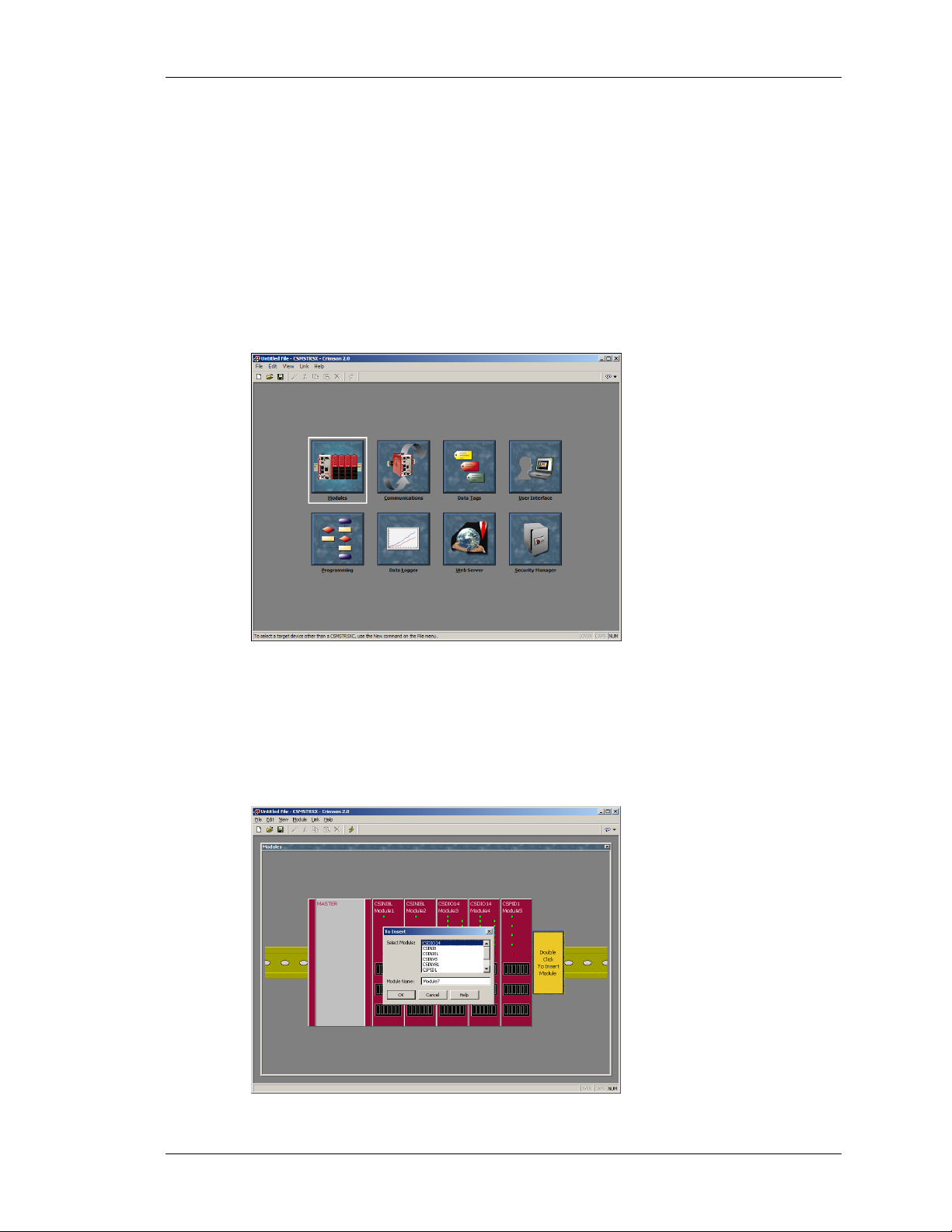
OVERVIEW
For the simplest of applications, only the first two icons eg. Modules and Communications,
are necessary. The former configures the system, allowing you to add, delete and edit
modules, while the latter allows module data to be mapped to an external device(s).
MODULES
The first step in the configuration of a database is to create and configure the various modules
used in the application. This is done under the Modules window of Crimson.
To insert a module into the system, double click on the blank base. You will be prompted to
choose the type of module to insert. You may also provide a descriptive name for the module.
REVISION 6 PAGE 3
Page 22
COMMUNICATIONS CRIMSON USER MANUAL - MODULAR CONTROLLER
Edit the individual module’s properties by double-clicking it. Each module and its properties
are explained in detail in later sections.
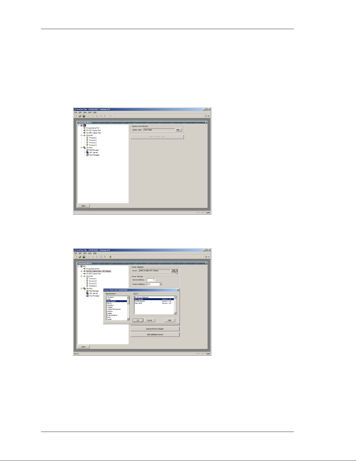
COMMUNICATIONS
Next, you’ll want to configure a port to communicate data to your PLC, PC, etc. The ports are
configured under the Communications window of the software. Click the Edit button in the
driver selection area to choose a protocol.
In the example below, Allen Bradley DF1 Master has been selected as the protocol. By doing
so, a device called PLC1 has been created. You should verify that the driver properties eg.
parity, baud rate, address, etc. make sense for your application.
MAPPING DATA
To map data between the Modular Controller and an external device, you’ll need to create
two so-called Gateway Blocks; one for moving module data into your device, and one for
getting module data from your device.
PAGE 4 http://www.redlion.net/controller
Page 23
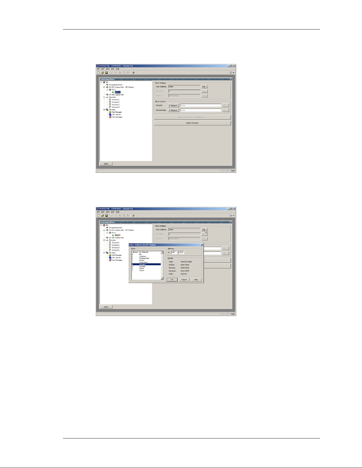
QUICK START MAPPING DATA
To create a Gateway Block, click PLC1, and then click the Add Gateway Block button on the
right hand pane. This creates a single gateway block for mapping data…
Next, you’ll need to identify the register locations that you wish to map data to or from,
starting with a register address. Click the Edit button to see the registers supported by
Crimson for the selected protocol…
Enter the desired number of registers in the Block Size property, as well as the desired
direction using the Direction property.
In our example below, registers N7:0 through N7:16 have been allocated.
REVISION 6 PAGE 5
Page 24
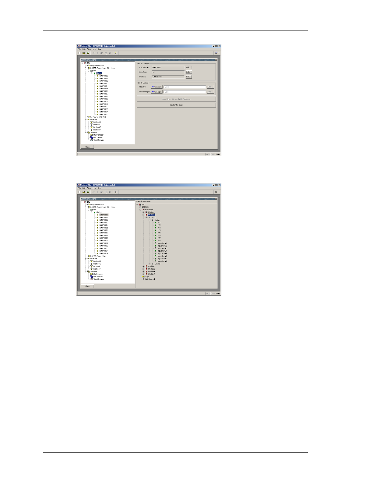
MAPPING DATA CRIMSON USER MANUAL - MODULAR CONTROLLER
To map module data, select one of the registers. A list of available data will be shown in the
right hand pane…
To map items from the right hand pane to the items on the left, simply double click them, one
at a time. The cursor will automatically move to the next consecutive register, allowing you to
quickly map all of the items. Instead of clicking the data in the right hand pane, you may also
drag and drop the data onto specific registers.
PAGE 6 http://www.redlion.net/controller
Page 25
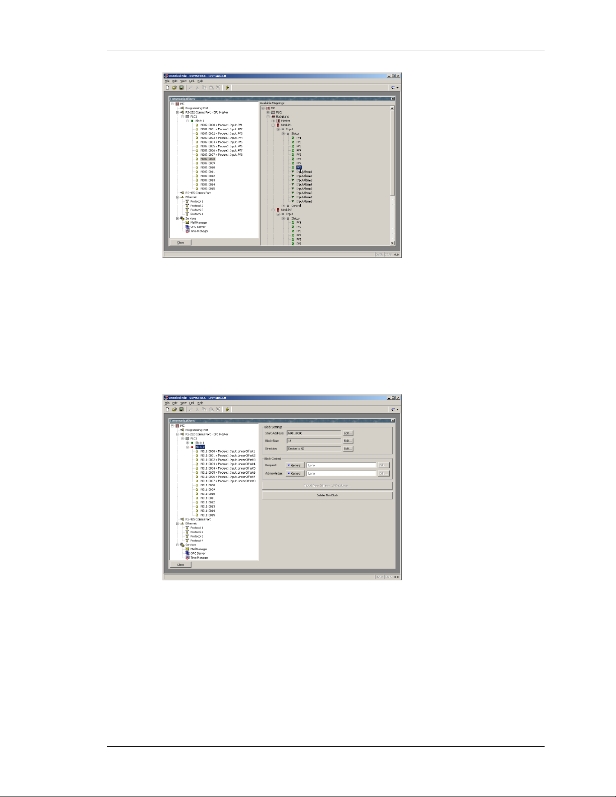
QUICK START DOWNLOADING
In the example above, each of the first module’s input values have been mapped to registers
N7:0 through N7:7. The direction of the arrows indicates that the Modular Controller will
write these values into the PLC.
Next, another block is created to move data from the PLC to the Modular Controller. This is
done by changing the block’s Direction property to Device to MC. In the example below,
Module1’s offset values are mapped to registers N11:0 through N11:7. The Direction
property indicates that the MC will get the value from the PLC registers, and write them into
the module’s offset values.
DOWNLOADING
To download to the Master via serial is trivial. Simply make sure you’ve selected the proper
COM port under Link-Options.
REVISION 6 PAGE 7
Page 26

CONNECT THE TWO CRIMSON USER MANUAL - MODULAR CONTROLLER
If you plan to use the USB port to download to the Master, you should take the time to read
the section titled Installing the USB Drivers
. The Ethernet port isn’t configured from the
factory, so it can’t be used as a means to download an initial database.
CONNECT THE TWO
That’s it. Connect the device to the MC, and if you’ve selected a master protocol, the
Modular Controller will do the rest. Simply look at the target registers, and you should see the
data being written to them. Try changing the registers that have been set for Device to MC,
and the modules should respond accordingly.
If you’ve configured the Modular Controller to act as a slave, you’ll have to initialize
whatever it is you’re using to communicate with the MC, and read and write the data
accordingly.
PAGE 8 http://www.redlion.net/controller
Page 27
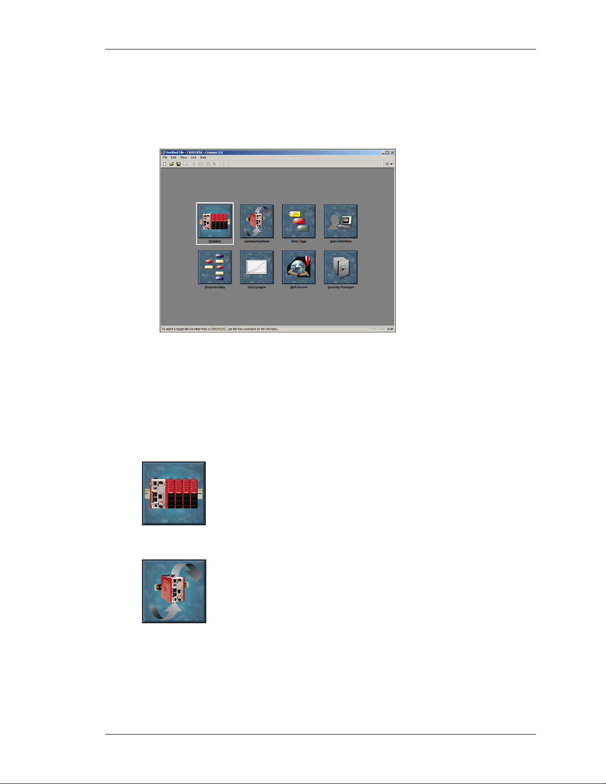
CRIMSON BASICS MAIN SCREEN ICONS
CRIMSON BASICS
To run Crimson, select the Crimson icon from the Red Lion Controls folder on the Programs
section of your Start Menu. The main C2 screen will appear, showing the icons that are used
to configure the various aspects of the Modular Controller’s behavior…
The software is designed such that the first three icons are the only ones required for the
majority of simple applications. The remainder of the icons provide access to the Master’s
more advanced features, such as programming, data logging and the web server.
MAIN SCREEN ICONS
The sections below provide an overview of each icon in turn…
M
ODULES
This icon is used to configure the modules within the system. Modules may
be added, deleted, or have their order on the rail modified. Each module may
then be accessed in order to configure their specific properties.
C
OMMUNICATIONS
This icon is used to specify which protocols are to be used on the Master’s
serial ports and on the Ethernet port. Where master protocols are used (ie.
protocols by which the Master module initiates data transfer to and from a
remote device) you can also use this icon to specify one or more devices to
be accessed. Where slave protocols are used (ie. protocols by which the
Master receives and responds to requests from remote devices or computer systems) you can
specify which data items are to be exposed for read or write access. You can also use this icon
to move data between one remote device and another via Crimson’s protocol converter.
REVISION 6 PAGE 9
Page 28
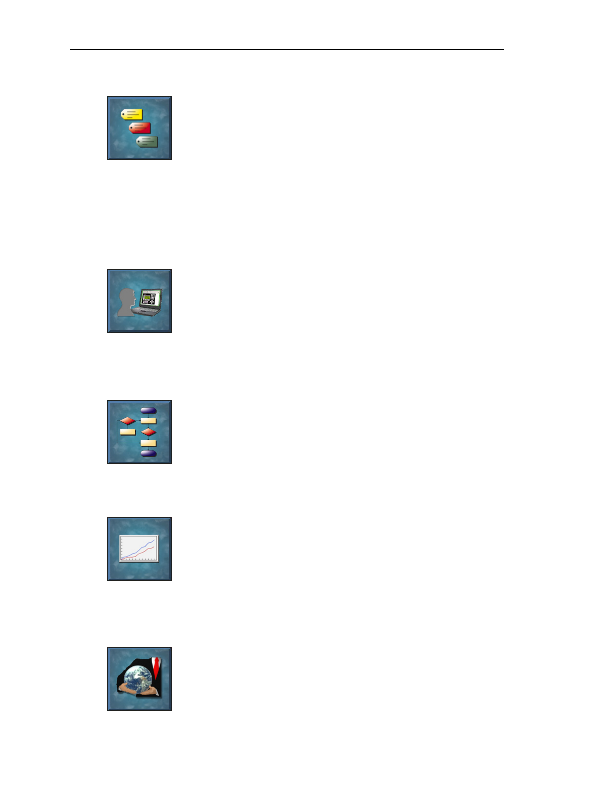
MAIN SCREEN ICONS CRIMSON USER MANUAL - MODULAR CONTROLLER
DATA TAGS
This icon is used to rename data items from the modules, as well as to define
items be accessed within the remote devices. It also allows the creation of
internal data items to store information within the Master itself. Each tag has
a variety of properties associated with it. The most basic property is
formatting data, which is used to specify how the data held within a tag is to
be shown on the Master’s virtual HMI, and on such things as web pages. By specifying this
information within the tag, Crimson removes the need for you to re-enter formatting data each
time a tag is displayed. More advanced tag properties include alarms that may activate when
various conditions relating to the tag occur, or triggers, which perform programmable actions
on similar conditions.
U
SER INTERFACE
This icon is used to create and edit display pages of the virtual HMI, and to
specify what actions should be taken when the HMI’s keys are pressed,
released or held down. The page editor allows you to display various
graphical items known as primitives. These vary from simple items, such as
rectangles and lines, to more complex items that can be tied to the value of a
particular tag or expression. By default, such primitives use the formatting information
defined when the tag was created, but this information can be overridden if required.
P
ROGRAMMING
This icon is used to create and edit programs using C2’s unique C-like
programming language. These programs can perform complex decision
making or data manipulation operations based upon any data items within
the system. They serve to extend the functionality of Crimson beyond that of
the standard functions included in the software, thereby ensuring that even
the most complex applications can be tackled with ease.
D
ATA LOGGER
This icon is used to create and manage data logs, each of which can record
any number of variables to the Master’s CompactFlash card. Data may be
recorded as quickly as once per second. The recorded values will be stored
in CSV (comma separated variable) files that can easily be imported into
applications such as Microsoft Excel. The files can be accessed by
swapping-out the CompactFlash card, by mounting the card as a drive on a PC connected on
the Master’s USB port, or by accessing them via Crimson’s web server via the Ethernet port.
W
EB SERVER
This icon is used to configure Crimson’s web server and to create and edit
web pages. The web server is capable of providing remote access to the
Master via a number of mechanisms. First, you can use Crimson to create
automatic web pages which contain lists of tags, each formatted according to
the tag’s properties. Second, you can create a custom site using a third party
PAGE 10 http://www.redlion.net/controller
Page 29
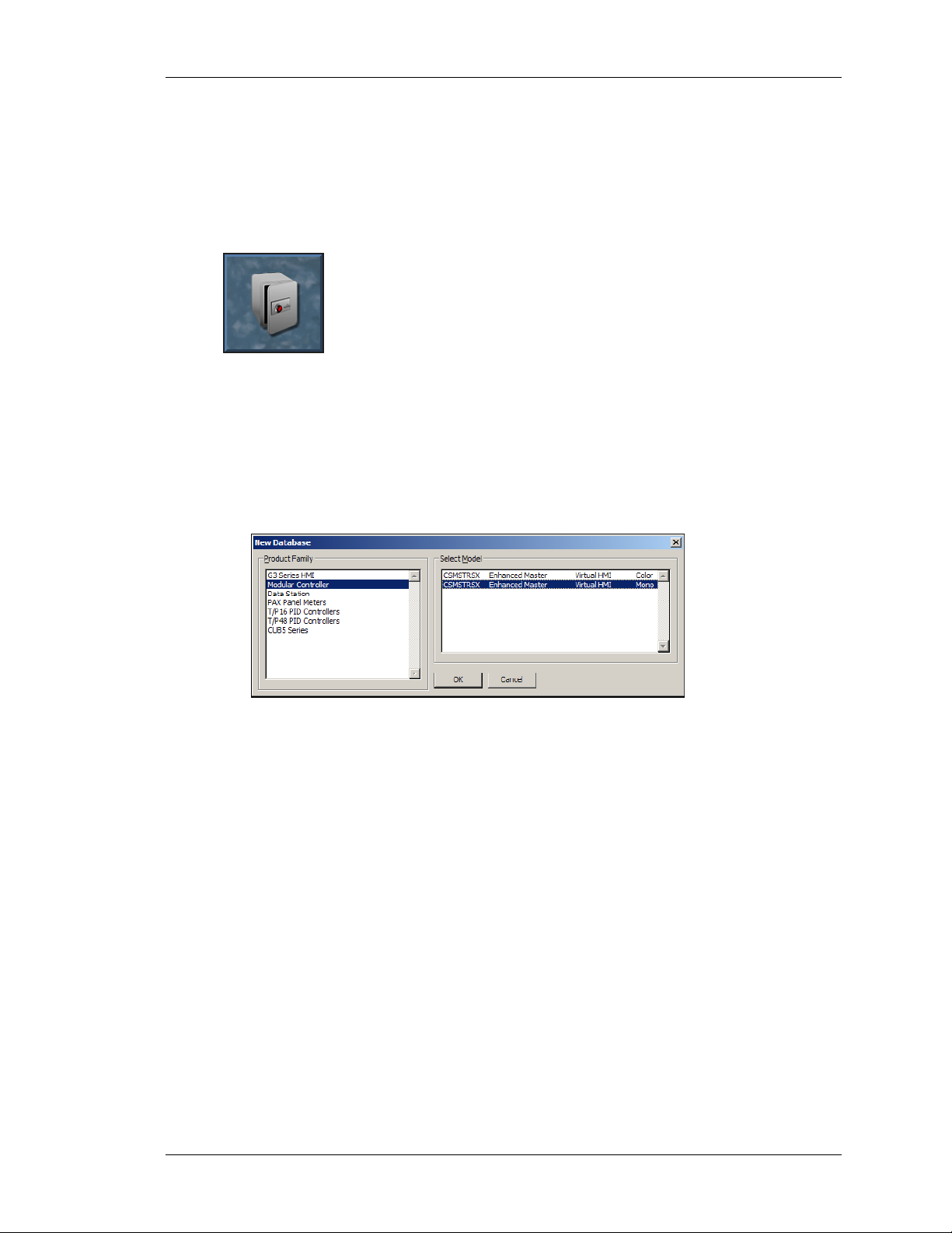
CRIMSON BASICS SELECTING THE MODULAR CONTROLLER
HTML editor such as Microsoft FrontPage, and then include special text to instruct Crimson
to insert live tag values. Finally, you can enable C2’s unique remote access and control
feature, which allows a web browser to view the Master’s virtual HMI and control its
keyboard. The web server can also be used to access CSV files from the Data Logger.
S
ECURITY MANAGER
This icon is used to create and manage the various users of the panel, as well
as the access rights granted to them. Real names may also be given, which
allows the security logger to record not only what data was changed and
when, but also by whom the data was changed. The rights required to
modify a particular tag, or to access a page, are set via the security
properties of the individual item.
SELECTING THE MODULAR CONTROLLER
When Crimson first starts, it will assume that you are continuing to work with the same Red
Lion device as was used by the last loaded database. If Crimson has not been previously
executed, it will assume you are working with a G303 HMI. To configure the Modular
Controller, select the New command from the File menu. The following dialog will appear…
The dialog lists the devices supported by the current version of the software, providing a
description of each. Selecting a device will create a blank database, and reconfigure Crimson
to work with that specific product.
REVISION 6 PAGE 11
Page 30

USING BALLOON HELP CRIMSON USER MANUAL - MODULAR CONTROLLER
USING BALLOON HELP
Crimson provides a useful feature called Balloon Help...
This feature allows you to see help information for each icon in the main menu, or for each
field in a dialog box or window. It is controlled via the icon at the right-hand edge of the
toolbar, and can be configured to three modes, namely “Do Not Display”, in which case
balloon help is disabled; “When Mouse Over”, in which case help is displayed when the
mouse pointer is held over a particular field for a certain period of time; or “When Selected”,
in which case help is always displayed for the currently selected field.
WORKING WITH DATABASES
Crimson stores all the information about a particular device’s configuration in what is called a
database file. These files have the extension of
CD2, although Windows Explorer will hide
this extension if it is left in its default configuration. Crimson database files differ from those
used by previous Red Lion products, in that they are text files which are thus far easier to
recover in the case of accidental corruption. Databases are manipulated via the commands
found on the File menu. These commands are standard for all Windows applications, and
need no further explanation. The exception is Save Image, which will be covered later.
DOWNLOADING TO THE MASTER
Crimson database files are downloaded to the Master by means of the Link menu. The
download process typically takes only a few seconds, but can take somewhat longer on the
first download if Crimson has to update the firmware in the Master, or if the Master does not
contain an older version of the current database. After this first download, however, Crimson
uses a process known as incremental download to ensure that only changes to the database are
transferred. This means that changes can be made in seconds, thereby reducing your
development cycle time and simplifying the debugging process.
C
ONFIGURING THE LINK
The programming link between the PC and the Master is made using an RS-232 serial port, a
USB port or a TCP/IP connection. While TCP/IP connections are typically made via the
PAGE 12 http://www.redlion.net/controller
Page 31

CRIMSON BASICS DOWNLOADING TO THE MASTER
Master’s Ethernet port, they may also be established via a dial-in link. Before downloading,
you should use the Link-Options command to ensure that you have the method selected…
ERIFYING THE USB LINK
V
If you are using USB, you might also want to ensure that the Master’s USB drivers have been
correctly installed. To do this, connect the Master module, and, if the drivers have not
previously been installed, follow the instructions at the start of this manual. Then, open the
Device Manager for your operating system, and expand the USB icon to show the icon for the
Master module device. Ensure that this icon does not display a warning symbol. If it does,
remove the device, unplug and reconnect the Master module, and verify that you have
correctly followed the driver installation procedure. The illustrations below show typical
Device Manager views with the CompactFlash dismounted and mounted, respectively….
ETTING THE IP ADDRESS
S
If you are using a TCP/IP connection, you should enter the IP address of the target device in
the appropriate field in the dialog box. If you leave the IP address as 0.0.0.0, Crimson will
examine the currently loaded database to see if the Master’s address can be determined from
the configuration information. This feature removes the need to change the IP addresses when
switching between databases intended for different terminals.
S
ENDING THE DATABASE
Once the link is configured, the database can be downloaded using either the Link-Send or
Link-Update commands. The former will send the entire database, whether or not individual
objects within the file have changed. The latter will only send changes, and will typically take
a much shorter period of time to complete. The Update command is typically the only one
REVISION 6 PAGE 13
Page 32

DOWNLOADING TO THE MASTER CRIMSON USER MANUAL - MODULAR CONTROLLER
that you will need, as Crimson will automatically fall-back to a complete send if the
incremental download fails for any reason. As a shortcut, note that you can access Link
Update via the lightning-bolt symbol on the toolbar, or via the
F9 key on the PC.
Note that downloading via TCP/IP relies on a CompactFlash card being installed in the
Master if the device’s firmware is to be upgraded. Since you may want to perform such
upgrades at some point in time, it is highly recommended that you install a CompactFlash
card in any device to which TCP/IP downloads are likely to be performed.
E
XTRACTING DATABASES
The Link-Support Upload command can be used to instruct Crimson whether or not it should
include the information necessary to support database upload when sending a database to a
Master module. Supporting upload will slow the download process somewhat and may fail
with extremely large databases containing many embedded images, but it will ensure that if
you lose your database file, you will be able to extract an editable image from the terminal.
Note that if you lose your database file and you do not have upload support enabled, you will
not be able to reconstruct your file without starting from scratch. To extract a database from a
Master, use the Link-Extract command. This command will upload the database, and then
prompt you for a name under which to save the file. The file will then be opened for editing.
M
OUNTING THE COMPACTFLASH
If you are connected to a Master module via the USB port, you can instruct Crimson to mount
the Master’s CompactFlash card as a drive within Windows Explorer. You can use this
functionality to save files to the card or to read information from the Data Logger. The drive
is mounted and dismounted by sending commands using the Mount Flash and Dismount
Flash options on the Link menu. Once a command has been sent, the Master module will be
reset, and Windows will refresh the appropriate Explorer windows to show or hide the
CompactFlash drive.
PAGE 14 http://www.redlion.net/controller
Page 33

CRIMSON BASICS DOWNLOADING TO THE MASTER
Note that some caution is required when mounting the CompactFlash card...
• When the card is mounted, the Master will periodically inform the PC if data on
the card has been modified. This means that both the PC and the Master will
suffer performance hits if the card is mounted during data logging operations for
longer than necessary.
• If you write to the CompactFlash card from your PC, the Master will not be able
to access the card until Windows releases its “lock” on the card’s contents. This
may take up to a minute, and will restrict data logging operations during that
time, and prevent access to custom web pages. Crimson will use the Master’s
RAM to ensure that no data is lost, but if too many writes are performed such
that the card is kept locked for four minutes or more, data may discarded. Note
that Windows 98 is particularly bad at keeping the card locked when there is no
need for it. Windows 2000 or Windows XP is thus the operating system of
choice when using this feature.
• You should never
attempt to use Windows to format a CompactFlash card that
you have mounted via the Master, whether it be via Explorer or from the
command prompt. Windows does not correctly lock the card during format
operations, and the format may thus be unreliable and lead to subsequent data
loss. See below for details of how to format a card in a reliable manner.
F
ORMATTING THE COMPACTFLASH
The preferred method of formatting a card is via the Format Flash command on the Link
menu. Selecting this command will explain that the formatting process will destroy all the
data stored on the CompactFlash card and offer you a chance to cancel the operation. If you
elect to continue, the Master will be instructed to format the card. Note that this process may
take several minutes for a large card. Slow formats on Masters that are performing data
logging may therefore result in gaps in the recorded data.
A less attractive method of formatting a card is via a dedicated CompactFlash drive connected
to your PC. If you use this method, be sure to instruct Windows to format the card using
FAT16. For very small or very large cards, Windows will most likely choose the wrong
format by default. Worse still, some versions of Windows Explorer will not allow you to
override the default format, forcing you to use the command line version
REVISION 6 PAGE 15
FORMAT instead.
Page 34

UPDATING VIA COMPACTFLASH CRIMSON USER MANUAL - MODULAR CONTROLLER
SENDING THE TIME AND DATE
The Link-Send Time command can be used to set the Master’s clock to match that of the PC
on which Crimson is executing. Obviously, make sure your clock is right before you do this!
UPDATING VIA COMPACTFLASH
If you need to update the database within a unit that is already installed at a customer’s site,
Crimson allows you to save a copy of the database to a CompactFlash card, ship that card to
your customer, and have the G3 load the database from that card. The process is performed
via the Save Image command on the File menu.
The Save Image command will create a Crimson database image file with a
will also create three other files with extensions of
given the name
DBASE.CDI, and it, along with the BIN, LDR and ROM files, must be placed in
BIN, LDR and ROM. The image file must be
CDI extension. It
the root directory of a CompactFlash card. To update a Master module, power down the unit,
insert the CompactFlash card bearing the four files, and reapply power to the unit. The
Master’s boot loader will first check whether it needs to upgrade the unit’s firmware, and
once this process has been completed, the Crimson runtime application will load the database
stored on the card. The CompactFlash card can then be removed or left in place as required.
PAGE 16 http://www.redlion.net/controller
Page 35

MODULE CONFIGURATION WORKING WITH MODULES
MODULE CONFIGURATION
The first step in the configuration of a database for the Modular Controller is to create and
configure the various modules used in the application. This is done under the Modules
window of Crimson.
WORKING WITH MODULES
INSERTING MODULES
To insert a module into the system, double click on the blank base. You will be prompted to
choose the type of module to insert. You may also provide a descriptive name for the module.
If you are going to program multiple modules the same, program just one, and then use the
Copy and Paste functions to create duplicates. This can be done by right-clicking a module or
the base, or by using standard Windows commands eg.
M
OVING MODULES
Modules may be deleted or moved through use of the Module drop-down menu. Simply
select a module, and then from the menu, select Delete, Move Left or Move Right.
Ctrl+C and Ctrl+V.
E
DITING MODULES
To edit a specific module’s properties, double-click it. For a description of the various
modules and their properties, refer to the following sections.
REVISION 6 PAGE 17
Page 36

CSPID – PID MODULE PROGRAMMING CRIMSON USER MANUAL - MODULAR CONTROLLER
CSPID – PID MODULE PROGRAMMING
The CSPID module’s parameters are broken into groups, each with their own page. The
CSPID2 module has several extra tabs for configuration of the second loop. Use the tabs on
the left hand side of the window to view the various pages.
T
HE GENERAL TAB
PERATION
O
• The Control Type property allows you to choose from Heat, Cool, or Heat and
Cool, depending on the type of process to be controlled. For processes other than
thermal applications, select Heat for reverse acting applications, and Cool for
direct acting applications.
• The Input Type property is used to configure the input for RTD, Thermocouple,
or the proper process input type.
• The TC/RTD property is used to select the sensor standard being used.
• The Input Filter is a time constant used to stabilize fluctuating input signals.
U
NITS
• Temperature Units is used to select between the Kelvin, Fahrenheit, or Celsius
temperature scale.
• The Process Units property allows you to enter the engineering units for the
process. This is only used to identify the appropriate fields throughout the
software. This parameter is saved as part of the Crimson file, but is not used
within the module.
• The Decimal Places property is used to allow Crimson to display the engineering
units in the proper resolution. This is only used to display the appropriate
resolution throughout the software, and is not used within the module.
PAGE 18 http://www.redlion.net/controller
Page 37

MODULE CONFIGURATION CSPID – PID MODULE PROGRAMMING
• The Process at 0% and Process at 100% properties are used to scale DC input
signals. Enter the desired PV reading for the minimum and maximum input
signal levels. For example, if the application involves a flow sensor with a 4 to
20 mA output proportional to 5 to 105 GPM, select Process 4-20mA for the
Input Type, enter 5 for the Process at 0% setting, and enter 105 for the Process
at 100% setting.
I
NITIALIZATION
The initialization parameters provide initial values for settings usually controlled by a PC or
PLC. In typical applications, these settings will only be used until communications is
established for the first time.
• The Include in Download property is used to determine whether the initialization
values will be downloaded to the module. Selecting “no” allows the modification
and download of databases at will, without accidental overwriting of the
established process parameters such as the setpoint, PID values, etc.
• The PID Parameters property dictates which PID parameters the module will
load, and subsequently use, to control the process. The module controls the
process using the Active PID values and Active Power Filter. (See
ActConstI, ActConstD, and ActFilter variables in the Available Data chart at
ActConstP,
the end of this section.) The active set is loaded with either the User PID
Settings, or the Auto-Tune Results values, depending on the state of the
ReqUserPID bit. If the bit is true, the Active set is loaded with the user’s
variables. If the bit is false, the values that were established by auto-tune are
loaded. Adjusting the PID Parameters property writes the
ReqUserPID bit
appropriately upon initialization.
• The Control Mode property dictates whether the module will in auto or manual
mode upon initialization. In auto mode, the controller calculates the required
output to reach and maintain setpoint, and acts accordingly. In manual mode, the
output can be controlled directly by writing to the
power variable.
• The Initial Setpoint property is used as the setpoint value upon initialization.
• Manual Power is the level the PID module will assume in manual mode. Values
in excess of 100% and –100% can be entered to overcome the limitations caused
by Power Transfer values, such as gains and offsets that would otherwise limit
the outputs to less than their maximums.
S
MARTONOFF
SmartOnOff is designed for situations where on-off control would normally be used, but
where the advantages of PID are also desired. When heat or cool is placed into this mode, the
control output will either be driven on or off, with no intermediate values or time
proportioning. However, rather than use the process value to decide when to turn the output
on, SmartOnOff looks at the output of the PID calculation and activates the output when it
exceeds half the defined gain for that channel. For example, with default settings,
REVISION 6 PAGE 19
Page 38

CSPID – PID MODULE PROGRAMMING CRIMSON USER MANUAL - MODULAR CONTROLLER
SmartOnOff for heating would turn the heat output on once the PID algorithm called for 50%
power or more, with the hysteresis value being used to ensure that small changes in the PID
calculation do not produce relay chatter.
• The Hysteresis property is used to eliminate output chatter by separating the on
and off points of the output(s) when performing SmartOnOff control. The
Hysteresis value is centered around the setpoint, that is, the transition points of
the output are offset above and below the setpoint by half the Hysteresis value.
T
HE CONTROL TAB
ETPOINT
S
• The Ramp Timebase property selects seconds, minutes, or hours as the unit of
time for ramping of the process.
• The Ramp Rate property is used to reduce sudden shock to a process during
setpoint changes and system startup, a setpoint ramp rate can be used to increase
or decrease the Actual Setpoint at a controlled rate. The value is entered in
units/time. A value of 0 disables setpoint ramping. If the Setpoint Ramp Rate is a
non-zero value, and the Requested Setpoint is changed or the module is powered
up, the controller sets the Actual Setpoint to the current process measurement,
and uses that value as its setpoint. It then adjusts the Actual Setpoint according
to the setpoint Ramp Rate. When the Actual Setpoint reaches the Requested
Setpoint, the controller resumes use of the Requested Setpoint value. (In a
properly designed and functioning system, the process will have followed the
Actual Setpoint value to the Requested Setpoint value.)
• The On/Off Hysteresis property is used to eliminate output chatter by separating
the on and off points of the output(s) when performing on/off control. The
hysteresis value is centered around the setpoint, that is, the transition points of
the output will be offset above and below the setpoint by half of the On/Off
Hysteresis value. This value effects outputs programmed for Heat or Cool.
During auto-tune, the controller cycles the process through 4 on/off cycles, so it
PAGE 20 http://www.redlion.net/controller
Page 39

MODULE CONFIGURATION CSPID – PID MODULE PROGRAMMING
is important to set the On-Off Hysteresis to an appropriate value before
initializing auto-tune.
• The On-Off Deadband property provides a means of offsetting the on-points of
heat and cool outputs programmed for on/off operation. This results in a
deadband if the value is positive, and overlap if the value is negative. When
determining the actual transition points of the outputs, the On/Off Hysteresis
value must also be taken into consideration.
A
UTO-TUNE SETTINGS
• The Tune Response property is used to ensure that an auto-tune yields the
optimal P, I, and D values for varying applications. A setting of Very Aggressive
results in a PID set that will reach setpoint as fast as possible, with no concern
for overshoot, while a setting of Very Conservative sacrifices speed in order to
prevent overshoot.
• Note: If the Tune Response property is changed, auto-tune needs to be reinitiated
for the changes to affect the PID settings. See the Auto-Tuning Section for more
information.
U
SER PID SETTINGS
• The Proportional Band property, entered as a percentage of the full input range,
is the amount of input change required to vary the output full scale. For
temperature inputs, the input range is fixed per the entered thermocouple or RTD
type. For process inputs, the input range is the difference between the Process at
0%, and Process at 100% values. The Proportional Band is adjustable from
0.0% to 1000.0%, and should be set to a value that provides the best response to
a process disturbance while minimizing overshoot. A Proportional Band of 0.0%
forces the controller into On/Off Control with its characteristic cycling at
setpoint. The optimal value may be established by invoking Auto-tune.
• The Integral Time is the time in seconds that it takes the integral action to equal
the proportional action, during a constant process error. As long as the error
exists, integral action is repeated each Integral Time. The higher the value, the
slower the response. The optimal value may be established by invoking autotune. The Integral Time is adjustable from 0 to 6000.0 seconds.
• The Derivative Time is the seconds per repeat that the controller looks ahead at
the ramping error to see what the proportional contribution will be and it
matches that value every Derivative Time. As long as the ramping error exists,
the derivative contribution is repeated every derivative time. Increasing the value
helps to stabilize the response, but too high of a value, coupled with noisy signal
processes, may cause the output to fluctuate too greatly, yielding poor control.
Setting the time to zero disables derivative action. The optimal Derivative Time
may be established by invoking auto-tune. The value is adjustable from 0 to
600.0 seconds.
REVISION 6 PAGE 21
Page 40

CSPID – PID MODULE PROGRAMMING CRIMSON USER MANUAL - MODULAR CONTROLLER
• The Power Filter is a time constant, entered in seconds, that dampens the
calculated output power. Increasing the value increases the dampening effect.
Generally, a Power Filter in the range of one-twentieth to one-fiftieth of the
controller’s integral time (or process time constant) is effective. Values longer
than these may cause controller instability due to the added lag effect.
T
HE POWER TAB
OWER TRANSFER
P
• The Output Offset value effectively shifts the zero output point of the module’s
output power calculation. This feature is most commonly used in proportionalonly applications, to remove steady-state error.
• The Output Deadband property defines the area in which both the heating and
cooling outputs are inactive, known as deadband, or the area in which they will
both be active, known as overlap. A positive value results in a deadband, while a
negative value results in an overlap.
• The Output Heat Gain defines the gain of the heating output relative to the gain
established by the Proportional Band. A value of 100% causes the heat gain to
mimic the gain determined by the proportional band. A value less than 100% can
be used in applications in which the heater is oversized, while a value greater
than 100% can be used when the heater is undersized. For the majority of
applications the default value of 100% is adequate, and adjustments should only
be made if the process requires it.
• The Output Cool Gain defines the gain of the cooling output relative to the gain
established by the Proportional Band. A value of 100% causes the cool gain to
mimic the gain determined by the proportional band. A value less than 100% can
be used in applications in which the cooling device is oversized, while a value
greater than 100% can be used when the cooling device is undersized. For the
majority of applications the default value of 100% is adequate, and adjustments
should only be made if the process requires it.
PAGE 22 http://www.redlion.net/controller
Page 41

MODULE CONFIGURATION CSPID – PID MODULE PROGRAMMING
• The Heat Low Limit and Heat High Limit properties may be used to limit
controller power due to process disturbances or setpoint changes. Enter the safe
output power limits for the process. You may enter values in excess of 100% and
–100% to overcome limitations caused by power transfer values, such as gains
and offsets, which would otherwise limit the output to less than their maximums.
• The Cool Low Limit and Cool High Limit properties may be used to limit
controller power due to process disturbances or setpoint changes. Enter the safe
output power limits for the process. You may enter values in excess of 100% and
–100% to overcome limitations caused by power transfer values, such as gains
and offsets, which would otherwise limit the output to less than their maximums.
T
RANSFER GRAPH
The power transfer graph illustrates the results of changes made to the power settings. The
blue line represents the cooling, while the red line represents the heating.
THE ALARMS TAB
The four “soft” process alarms may be used to monitor process status, and may be used to
actuate the module’s physical outputs. Otherwise, the bit alone may be monitored via the
system itself, or via external devices.
• The Mode property determines what behavior the alarm will assume. The table
below describes the various selections.
MODE DESCRIPTION
Absolute Low
Absolute High
REVISION 6 PAGE 23
The alarm activates when the Process Value falls below
the Alarm Value. The alarm deactivates when the Process
Value goes above the Alarm Value + Hysteresis.
The alarm activates when the Process Value exceeds the
Alarm Value. The alarm deactivates when the Process
Value falls below the Alarm Value – Hysteresis.
Page 42

CSPID – PID MODULE PROGRAMMING CRIMSON USER MANUAL - MODULAR CONTROLLER
MODE DESCRIPTION
Deviation Low
Deviation High
In Band
Out of Band
If the Process Value falls below the Setpoint Value by the
amount of the Alarm Value, the alarm activates. In this
mode, the alarm point tracks the Setpoint Value.
If the Process Value exceeds the Setpoint Value by the
amount of the Alarm Value, the alarm activates. In this
mode, the alarm point tracks the Setpoint Value.
If the difference between the Setpoint Value and the
Process Value is not greater than the Alarm Value, the
alarm activates.
If the Process Value exceeds, or falls below, the Setpoint
Value by an amount equal to the Alarm Value, the alarm
activates. In this mode, the alarm point tracks the Setpoint
Value.
• The Value property is the point at which the alarm will turn on. The alarm values
are entered as process units or degrees.
• The Hysteresis value separates the on and off points of the alarm ie. a high acting
alarm programmed to turn on at 500 with a Hysteresis of 10, will turn off when
the PV falls below 490.
• The Latching property dictates how the alarm behaves once activated. See the
Alarm Behavior Chart below for more information.
• The Standby property provides a means of preventing so called nuisance alarms
during power up. See the Alarm Behavior Chart below for more information.
A
LARM BEHAVIOR CHART
LATCHING STANDBY ALARM BEHAVIOR
Alarm automatically turns on and off as the Process Value crosses in and out of
the alarm region.
The AlarmAccept bit disables alarm, regardless of the state of the process. If the
alarm condition exists, and the bit is written to a “0”, the alarm activates.
Once activated, the alarm stays active until accepted.
If the alarm condition no longer exists, writing the Alarm Accept bit to “1”
resets the alarm condition.
As long as the Alarm Accept bit is “1”, the alarm automatically turns on and off
as the Process Value crosses in and out of the alarm region.
PAGE 24 http://www.redlion.net/controller
Page 43

MODULE CONFIGURATION CSPID – PID MODULE PROGRAMMING
LATCHING STANDBY ALARM BEHAVIOR
HEATER CURRENT
Alarm automatically turns on and off as the Process Value crosses in and out of
the alarm region.
The alarm is automatically disabled when a setpoint change occurs, or when the
module is first powered up. This prevents nuisance alarms from occurring. The
alarm remains disabled until the process enters a non-alarm state. The next time
the Process Value enters an alarm condition, the alarm will activate accordingly.
The AlarmAccept bit disables the alarm, regardless of state. If the alarm
condition exists, and the bit is written to a “0”, the alarm activates.
Once activated, the alarm stays active until accepted.
The alarm is automatically disabled when a setpoint change occurs, or when the
module is first powered up. This prevents nuisance alarms from occurring. The
alarm remains disabled until the process enters a non-alarm state. The next time
the Process Value enters an alarm condition, the alarm will activate accordingly.
Momentarily writing the AlarmAccept bit to “1” turns off an active alarm. If the
alarm condition still exists, the alarm remains off and is placed into standby
mode. That is, the alarm will remain off until the alarm condition goes away,
and is then reentered.
If the AlarmAccept bit remains a “1”, the alarm is disabled, and will not function.
The Heater Current alarm is useful for monitoring the condition of external AC control
circuitry via the Heater Current Monitor input.
• The Channel property is used to select which one of the three discrete outputs
will be monitored.
• The Limit Low property is the desired mA value, from 0-100.00 mA that
represents the allowable circuit-off current. If the heater current monitor input
measures a current value greater than the Limit Low value during the off state of
the output, the alarm becomes active.
• The Limit High property is the desired mA value, from 0-100.00 mA that
represents the required circuit-on current value. If the heater current monitor
input measures a current value less than the Limit High value during the on state
of the output, the alarm becomes active.
• The Latching property determines whether an activated alarm will stay active
until accepted. To accept a latched alarm, its
AlarmAccept bit must be written to
a 1. If latching is not selected, the alarm will automatically deactivate when the alarm
condition no longer exists, and the
AlarmAccept bit may be used as a means of
disabling the alarm.
REVISION 6 PAGE 25
Page 44

CSPID – PID MODULE PROGRAMMING CRIMSON USER MANUAL - MODULAR CONTROLLER
INPUT FAULT
The Input Fault section is used to define the response of the CSPID module’s control outputs
in the event of an input failure. The Input Fault alarm is considered a process alarm for items
that may be mapped to “any process alarm”.
• The Set Output To property is the output value that the controller will assume in
the event of an input sensor failure. Values in excess of 100% and –100% may
be entered to overcome limitations caused by power transfer values, such as
gains and offsets, which would otherwise limit the output to less than their
maximums.
• The Latching property, if enabled, will cause the input fault bit to stay active
until accepted, regardless of the state of the input. To reset the fault, the
InputAccept bit must be written to a 1. If latching is not selected, the fault will
automatically deactivate when the input failure is corrected.
T
HE OUTPUTS TAB
IGITAL OUTPUTS
D
• The Output n properties are used to assign the module’s physical outputs to
various internal properties or values. The CSPID2’s list is expanded to include
the channel number eg. Channel 1 Heat Power, or Channel 2 Heat Power.
• The Cycle Time value is the sum of a time-proportioned output’s on and off
cycles. With time proportional outputs, the percentage of output power is
converted into output on time of the cycle time value eg. if the controller’s
algorithm calls for 65% power, and has a Cycle Time of 10 seconds, the output
will be on for 6.5 seconds and off for 3.5 seconds. A Cycle Time equal to, or less
than, one-tenth of the process time constant is recommended.
PAGE 26 http://www.redlion.net/controller
Page 45

MODULE CONFIGURATION CSPID – PID MODULE PROGRAMMING
LINEAR OUTPUT - (CSPID1 ONLY)
• The Output Type property is used to select between 0-10 V, 0-20 mA, or 4-20
mA outputs. Make sure that the output jumpers, located on the side of the
module, are set for the same output type.
• The Mapping property is used to assign the module’s analog output to one of
various internal properties or values eg. the Mapping property should be set to
Heat Power to control a heat-only process via the analog output.
• The Drive Min At and Drive Max At values are used to scale the analog output.
The units expressed are the same as those of the Mapping value, so the
numerical limits vary eg. values of 0% and 100% are typically used to control a
valve’s position in heat-only applications.
• The Output Filter is a time constant entered in seconds that dampens the
response of the analog output. Increasing the value increases the dampening.
• The Output Deadband value can be used to prevent the analog output from
changing when only small adjustments are called for. This is useful in preventing
mechanical wear when driving a linear input valve. The analog output will not
adjust unless the change called for exceeds half of the deadband value. i.e. With
a deadband of 10 %, and an output value of 50 %, the output will not change
until 45 % or 55 % is called for. The units expressed are the same as those of the
Mapping value.
• The Output Update time can be used to decrease the update frequency of the
analog output. When the Output Update timer expires, the analog output checks
to see if the required change is greater than the Output Deadband value. If the
required change is greater, the output will reflect the new value. If not, the output
does not change, and the timer starts again.
A
UTO-TUNING
VERVIEW
O
Auto-tune may be used to establish the optimal P, I, D, and Power Filter values. By cycling
the process through four on/off cycles, the module learns information about the process, and
determines the best values.
REVISION 6 PAGE 27
Page 46

CSPID – PID MODULE PROGRAMMING CRIMSON USER MANUAL - MODULAR CONTROLLER
As shown above, the setpoint used during auto-tune is the value 75 % above the difference
between the current PV and the setpoint. This allows the oscillations to occur close to
setpoint, while avoiding excessive overshoot. Since the module performs on/off control
during auto-tune, it is important to set a suitable On/Off Hysteresis value prior to invoking
auto-tune.
Customization of the PID set that auto-tune will yield is possible by adjusting the Tune
Response setting. The Tune Response setting can be set to Very Aggressive, Aggressive,
Default, Conservative, or Very Conservative. Further, the Tune Response setting can be
adjusted by writing 0-4 respectively to the Tune Response register.
I
NVOKING AUTO-TUNE
The auto-tune sequence uses request/acknowledgement handshaking. To invoke auto-tune,
write the
AckTune bit high. When auto-tune is complete, the TuneDone bit goes high. The external
logic should be written to turn off the auto-tune request bit when the
At this point, the module sets the
If for some reason auto-tune fails to complete, the
ReqTune bit to a 1. The module signifies that auto-tune is running by setting the
TuneDone bit goes high.
AckTune bit back to 0.
TuneDone and TuneFail bits both go high.
This situation may occur if, for example, an input fault occurs, and will require that auto-tune
be reinitialized.
An auto-tune request cycle looks like the following…
PAGE 28 http://www.redlion.net/controller
Page 47

MODULE CONFIGURATION CSPID – PID MODULE PROGRAMMING
1. PLC sets ReqTune high.
2. Module starts auto-tuning, sets
3. Auto-tune is complete.
4. PLC sees
5. Module sees
TuneDone high, sets ReqTune low.
ReqTune go low, and sets the TuneDone low.
AckTune goes low; TuneDone goes high.
AckTune high.
REVISION 6 PAGE 29
Page 48

CSPID – PID MODULE PROGRAMMING CRIMSON USER MANUAL - MODULAR CONTROLLER
AVAILABLE DATA
The following are the data values available to the Master, and therefore, may be mapped to
PLC registers. Decimal places are used to denote resolution only, and are not read or written
ie. a
Power value of 10000 is interpreted as 100.00%.
Note: The following table shows available data for the CSPID1 module. In most cases, the
CSPID2 module contains the same data for both Loop 1 and Loop 2. e.g. Instead of listing
only
Module1.PV, the CSPID2 will list Module1.Loop1.PV and Module1.Loop2.PV.
L
OOP/STATUS
DATA DESCRIPTION RANGE ACCESS
PV Process Value – The input value * R
Output
HeatPower Output applied to channels assigned for Heat 0 – 100.00% R
CoolPower Output applied to channels assigned for Cooling 0 – 100.00% R
ActSP Actual Setpoint * R
Error
ColdJunc Cold Junction Calibration Value N/A R
HCMValue Heater Current mA Input Value 0 – 100.00 mA R
AckManual Acknowledge Manual mode 0 or 1 (bit) R
AckTune Acknowledge auto-tune request 0 or 1 (bit) R
TuneDone Auto-tune completed 0 or 1 (bit) R
TuneFail Auto-tune did not finish successfully 0 or 1 (bit) R
Alarm1 Alarm 1 status 0 or 1 (bit) R
Alarm2 Alarm 2 status 0 or 1 (bit) R
Alarm3 Alarm 3 status 0 or 1 (bit) R
Alarm4 Alarm 4 status 0 or 1 (bit) R
Output Power – Calculated output power of the PID loop
prior to Gain, Offsets, and Limits
The difference between the Process Value and the
Requested Setpoint
+/- 200.00% R
* R
HCMAlarmLo Heater Current Monitor low limit alarm 0 or 1 (bit) R
HCMAlarmHi Heater Current Monitor high limit alarm 0 or 1 (bit) R
InputAlarm Input out of range 0 or 1 (bit) R
* Dependent on selected sensor type.
PAGE 30 http://www.redlion.net/controller
Page 49

MODULE CONFIGURATION CSPID – PID MODULE PROGRAMMING
LOOP/CONTROL
DATA DESCRIPTION RANGE ACCESS
ReqSP
Requested Setpoint – The setpoint value written to the
* R/W
controller. This value may be different than the Actual
Setpoint in applications utilizing Setpoint Ramping.
Power Manual output power setting +/- 200.00% R/W
SetHyst Setpoint Hysteresis for On/Off Control * R/W
SetDead Setpoint Deadband for On/Off Control * R/W
SetRamp Setpoint Ramp Rate * R/W
InputFilter Input Filter 0 – 60.0 sec R/W
ReqManual
Request Manual – Write this bit to a 1 to invoke manual
0 or 1 (bit) R/W
mode. In manual mode, writing to the Power register
controls the output power.
ReqTune Request auto-tune – Write this bit to a 1 to invoke auto-tune. 0 or 1 (bit) R/W
ReqUserPID
Request User PID Set – High loads User Values into Active
0 or 1 (bit) R/W
set, Low loads Auto-Tune Results into Active set.
LOOP/ALARMS
DATA DESCRIPTION RANGE ACCESS
AlarmData1 Alarm 1 Value * R/W
AlarmData2 Alarm 2 Value * R/W
AlarmData3 Alarm 3 Value * R/W
AlarmData4 Alarm 4 Value * R/W
AlarmHyst1 Alarm 1 Hysteresis value * R/W
AlarmHyst2 Alarm 2 Hysteresis value * R/W
AlarmHyst3 Alarm 3 Hysteresis value * R/W
AlarmHyst4 Alarm 4 Hysteresis value * R/W
AlarmAccept1 Alarm 1 Accept bit 0 or 1 (bit) R/W
AlarmAccept2 Alarm 2 Accept bit 0 or 1 (bit) R/W
AlarmAccept3 Alarm 3 Accept bit 0 or 1 (bit) R/W
AlarmAccept4 Alarm 4 Accept bit 0 or 1 (bit) R/W
HCMLimitLo Heater Current Low Limit Alarm value 0 – 100.00 mA R/W
HCMLimitHi Heater Current Low Limit Alarm value 0 – 100.00 mA R/W
HCMAcceptLo Heater Current Low Limit Alarm Accept 0 or 1 (bit) R/W
HCMAcceptHi Heater Current High Limit Alarm Accept 0 or 1 (bit) R/W
InputAccept Input out of range alarm accept 0 or 1 (bit) R/W
REVISION 6 PAGE 31
Page 50

CSPID – PID MODULE PROGRAMMING CRIMSON USER MANUAL - MODULAR CONTROLLER
LOOP/PID
DATA DESCRIPTION RANGE ACCESS
TuneCode Tune Response Code 0-4 R/W
UserConstP User Proportional Value 0 – 1000.0% R/W
UserConstI User Integral Value 0 – 6000.0 sec R/W
UserConstD User Derivative Value 0 – 600.0 sec R/W
UserFilter User Power Filter Value 0 – 60.0 sec R/W
AutoConstP Auto-tuned Proportional Value 0 – 1000.0% R
AutoConstI Auto-tuned Integral Value 0 – 6000.0 sec R
AutoConstD Auto-tuned Derivative Value 0 – 600.0 sec R
AutoFilter Auto-tuned Power Filter Value 0 – 60.0 sec R
ActConstP Active Proportional Value 0 – 1000.0% R
ActConstI Active Integral Value 0 – 6000.0 sec R
ActConstD Active Derivative Value 0 – 600.0 sec R
ActFilter Active Power Filter Value 0 – 60.0 sec R
LOOP/POWER
DATA DESCRIPTION RANGE ACCESS
PowerFault Power Output value for input fault +/- 200.00% R/W
PowerOffset Power Output Offset value +/- 100.00% R/W
PowerDead Power Output Deadband value +/- 100.00% R/W
PowerHeatGain Power Output Heat Gain value 0 – 500.00% R/W
PowerCoolGain Power Output Cool Gain value 0 – 500.00% R/W
PowerHeatHyst Power Output SmartOnOff Heat Hysteresis 0 – 50.00% R/W
PowerCoolHyst Power Output SmartOnOff Cool Hysteresis 0 – 50.00% R/W
HeatLimitLo Heat Low Limit 0 – 200.00% R/W
HeatLimitHi Heat High Limit 0 – 200.00% R/W
CoolLimitLo Cool Low Limit 0 – 200.00% R/W
CoolLimitHi Cool High Limit 0 – 200.00% R/W
PAGE 32 http://www.redlion.net/controller
Page 51

MODULE CONFIGURATION CSPID – PID MODULE PROGRAMMING
OUTPUTS/CYCLE TIMES
DATA DESCRIPTION RANGE ACCESS
CycleTime1 Cycle Time for Output 1 0.1 – 60.0 sec R/W
CycleTime2 Cycle Time for Output 2 0.1 – 60.0 sec R/W
CycleTime3 Cycle Time for Output 3 0.1 – 60.0 sec R/W
CycleTime4 Cycle Time for Output 4 (CSPID2 only) 0.1 – 60.0 sec R/W
OUTPUTS/REMOTE DATA
DATA DESCRIPTION RANGE ACCESS
DigRemote1
DigRemote2 Digital Remote 2 – See DigRemote1 0 or 1 (bit) R/W
DigRemote3 Digital Remote 3 – See DigRemote1 0 or 1 (bit) R/W
DigRemote4 Digital Remote 4 – See DigRemote1 0 or 1 (bit) R/W
AnlRemote1
AnlRemote2 Analog Remote Value 2 – See AnlRemote1 * R/W
AnlRemote3 Analog Remote Value 3 – See AnlRemote1 * R/W
AnlRemote4 Analog Remote Value 4 – See AnlRemote1 * R/W
Digital Remote 1 – Outputs assigned to Digital Remote
can be controlled by writing the DigRemote bit to a 1 or 0.
Analog Remote Value 1 – Outputs assigned to Analog
Remote can be controlled by writing a number to this
word.
0 or 1 (bit) R/W
* R/W
OUTPUTS/INFORMATION
DATA DESCRIPTION RANGE ACCESS
OP1State State of Output 1 0 or 1 (bit) R
OP2State State of Output 2 0 or 1 (bit) R
OP3State State of Output 3 0 or 1 (bit) R
* Configuration dependent. Except for the application detailed below, these numbers may be
treated as signed integers. All temperature inputs are measured to a tenth of a degree
resolution. For process inputs, the resolution is dependent on the user scaling values.
Application exception: If the application involves Fahrenheit measurement over 3000 degrees
with a C type thermocouple, the following values should be treated as unsigned – PV, ReqSP,
ActSP and AlarmData 1-4 (when configured for absolute operation).
REVISION 6 PAGE 33
Page 52

CSSG – STRAIN GAGE INPUT PID MODULE PROGRAMMING CRIMSON USER MANUAL - MODULAR CONTROLLER
CSSG – STRAIN GAGE INPUT PID MODULE PROGRAMMING
The CSSG module’s parameters are broken into groups, each with their own page. Use the
tabs on the left hand side of the window to view the various pages.
T
HE GENERAL TAB
NPUTS
I
The input parameters section contains settings for both inputs. If the module does not have the
optional secondary input fitted, the secondary input parameters are ignored.
• The Range property is used to configure the input for various signal levels. This
allows the module to reconfigure its A/D converter for optimal resolution.
• The Excitation property configures the output excitation voltage for either 5 or
10 Volts.
• The Display Low and Display High properties are used to scale the input to
indicate units of measure. Enter the desired PV readings that correspond to the
Signal Low and Signal High values, respectively. ie. If the application involves a
strain gage that produces a 0 to 21.00 mV output proportional to 0 to 1000 lbs,
enter 0 for the Display Low property, and 1000 for the Display High property.
• The Signal Low and Signal High properties are used to scale the input. Enter the
signal levels that correspond to the Display Low and Display High properties,
respectively. ie. If the application involves a strain gage that produces a 0 to
21.00 mV output proportional to 0 to 1000 lbs, enter 0 for the Signal Low
property, and +21.00 mV for the Signal High property.
O
PERATION
• The Control Type property allows you to choose from Reverse only, Direct only
or Reverse and Direct, depending on the type of process to be controlled.
PAGE 34 http://www.redlion.net/controller
Page 53

MODULE CONFIGURATION CSSG – STRAIN GAGE INPUT PID MODULE PROGRAMMING
• PV Assignment selects how the module determines its measured process value.
The PV value is the value that the module’s PID algorithm will attempt to
control. This can simply be the Input 1 value, or one of several mathematical
results of Input 1 and Input 2.
• The PV Limit Low and PV Limit High properties are used to establish the
working range of the PV value, and subsequently, the range over which the
module can control. The reported PV value remains frozen at either limit as the
process continues to move outside these boundaries. Exceeding either limit by
more than 5% of the full range results in the module assuming a process fault, at
which time the PV value reported becomes equal to the PV Limit High value
(upscale drive response).
• The Input Filter is a time constant used to stabilize fluctuating input signals.
• The Process Units property allows you to enter the engineering units for the
process. This is only used to identify the appropriate fields throughout the
software. This parameter is saved as part of the Crimson file, but is not used
within the module.
• The Decimal Places property is used to allow Crimson to display the engineering
units in the proper resolution. This is only used to display the appropriate
resolution throughout the software, and is not used within the module.
I
NITIALIZATION
The initialization parameters provide initial values for settings usually controlled by a PC or
PLC. In typical applications, these settings will only be used until communications is
established for the first time.
• The Include in Download property is used to determine whether the initialization
values will be downloaded to the module. Selecting “no” allows modification
and download of databases at will, without accidental overwriting of established
process parameters such as the setpoint, PID values, input scaling, etc.
• The PID Parameters property dictates which PID parameters the module will
load, and subsequently use, to control the process. The module controls the
process using the Active PID values and Active Power Filter. (See
ActConstI, ActConstD, and ActFilter variables in the Available Data chart at
ActConstP,
the end of this section.) The active set is loaded with either the User PID
Settings, or the Auto-Tune Results values, depending on the state of the
ReqUserPID bit. If the bit is true, the Active set is loaded with the user’s
variables. If the bit is false, the values that were established by auto-tune are
loaded. Adjusting the PID Parameters property writes the
ReqUserPID bit
appropriately upon initialization.
• The Control Mode property dictates whether the module will be in auto or
manual mode upon initialization. In auto mode, the controller calculates the
REVISION 6 PAGE 35
Page 54

CSSG – STRAIN GAGE INPUT PID MODULE PROGRAMMING CRIMSON USER MANUAL - MODULAR CONTROLLER
required output to reach and maintain setpoint, and acts accordingly. In manual
mode, the output can be controlled directly by writing to the
power variable.
• The Initial Setpoint property is used as the setpoint value upon initialization.
• Manual Power is the level the PID module will assume in manual mode. Values
in excess of 100% and –100% can be entered to overcome the limitations caused
by Power Transfer values, such as gains and offsets that would otherwise limit
the outputs to less than their maximums.
• The Download Scaling property determines which scaling values, if any, will be
downloaded to the module. To avoid overwriting the scaling values of a
calibrated process, set this value to No.
S
MARTONOFF
SmartOnOff is designed for situations where on-off control would normally be used, but
where the advantages of PID are also desired. When the reverse or direct output is placed into
this mode, the control output will either be driven on or off, with no intermediate values or
time proportioning. However, rather than use the process value to decide when to turn the
output on, SmartOnOff looks at the output of the PID calculation and activates the output
when it exceeds half the defined gain for that channel. For example, with default settings,
SmartOnOff for the reverse output would turn the output on once the PID algorithm called for
50% power or more, with the hysteresis value being used to ensure that small changes in the
PID calculation do not produce relay chatter.
• The Hysteresis property is used to eliminate output chatter by separating the on
and off points of the output(s) when performing SmartOnOff control. The
Hysteresis value is centered around the setpoint, that is, the transition points of
the output will be offset above and below the setpoint by half of the Hysteresis
value.
T
HE CONTROL TAB
PAGE 36 http://www.redlion.net/controller
Page 55

MODULE CONFIGURATION CSSG – STRAIN GAGE INPUT PID MODULE PROGRAMMING
SETPOINT
• The Ramp Timebase property selects seconds, minutes, or hours as the unit of
time for ramping of the process.
• The Ramp Rate property is used to reduce sudden shock to a process during
setpoint changes and system startup, a setpoint ramp rate can be used to increase
or decrease the Actual Setpoint at a controlled rate. The value is entered in
units/time. A value of 0 disables setpoint ramping. If the Setpoint Ramp Rate is a
non-zero value, and the Requested Setpoint is changed or the module is powered
up, the controller sets the Actual Setpoint to the current process measurement,
and uses that value as its setpoint. It then adjusts the Actual Setpoint according
to the setpoint Ramp Rate. When the Actual Setpoint reaches the Requested
Setpoint, the controller resumes use of the Requested Setpoint value. (In a
properly designed and functioning system, the process will have followed the
Actual Setpoint value to the Requested Setpoint value.)
• The On/Off Hysteresis property is used to eliminate output chatter by separating
the on and off points of the output(s) when performing on/off control. The
hysteresis value is centered around the setpoint, that is, the transition points of
the output will be offset above and below the setpoint by half of the On/Off
Hysteresis value. This value effects outputs programmed for Reverse or Direct.
During auto-tune, the controller cycles the process through 4 on/off cycles, so it
is important to set the On-Off Hysteresis to an appropriate value before
initializing auto-tune.
• The On-Off Deadband property provides a means of offsetting the on-points of
reverse and direct outputs programmed for on/off operation. This results in a
deadband if the value is positive, and overlap if the value is negative. When
determining the actual transition points of the outputs, the On/Off Hysteresis
value must also be taken into consideration.
A
UTO-TUNE SETTINGS
• The Tune Response property is used to ensure that an auto-tune yields the
optimal P, I, and D values for varying applications. A setting of Very Aggressive
results in a PID set that will reach setpoint as fast as possible, with no concern
for overshoot, while a setting of Very Conservative sacrifices speed in order to
prevent overshoot.
Note: If the Tune Response property is changed, auto-tune needs to be reinitiated for
the changes to affect the PID settings. See the Auto-Tuning Section for more
information.
U
SER PID SETTINGS
• The Proportional Band property, entered as a percentage of the full input range,
is the amount of input change required to vary the output full scale. The input
range is the difference between the PV Limit Lo and PV Limit Hi values. The
REVISION 6 PAGE 37
Page 56

CSSG – STRAIN GAGE INPUT PID MODULE PROGRAMMING CRIMSON USER MANUAL - MODULAR CONTROLLER
Proportional Band is adjustable from 0.0% to 1000.0%, and should be set to a
value that provides the best response to a process disturbance while minimizing
overshoot. A Proportional Band of 0.0% forces the controller into On/Off
Control with its characteristic cycling at setpoint. The optimal value may be
established by invoking Auto-tune.
• The Integral Time is the time in seconds that it takes the integral action to equal
the proportional action, during a constant process error. As long as the error
exists, integral action is repeated each Integral Time. The higher the value, the
slower the response. The optimal value may be established by invoking autotune. The Integral Time is adjustable from 0 to 6000.0 seconds.
• The Derivative Time is the seconds per repeat that the controller looks ahead at
the ramping error to see what the proportional contribution will be and it
matches that value every Derivative Time. As long as the ramping error exists,
the derivative contribution is repeated every derivative time. Increasing the value
helps to stabilize the response, but too high of a value, coupled with noisy signal
processes, may cause the output to fluctuate too greatly, yielding poor control.
Setting the time to zero disables derivative action. The optimal Derivative Time
may be established by invoking auto-tune. The value is adjustable from 0 to
600.0 seconds.
• The Power Filter is a time constant, entered in seconds, that dampens the
calculated output power. Increasing the value increases the dampening effect.
Generally, a Power Filter in the range of one-twentieth to one-fiftieth of the
controller’s integral time (or process time constant) is effective. Values longer
than these may cause controller instability due to the added lag effect.
T
HE POWER TAB
OWER TRANSFER
P
• The Output Offset value effectively shifts the zero output point of the module’s
output power calculation. This feature is most commonly used in proportionalonly applications, to remove steady-state error.
PAGE 38 http://www.redlion.net/controller
Page 57

MODULE CONFIGURATION CSSG – STRAIN GAGE INPUT PID MODULE PROGRAMMING
• The Output Deadband property defines the area in which both the reverse and
direct outputs are inactive, known as deadband, or the area in which they will
both be active, known as overlap. A positive value results in a deadband, while a
negative value results in an overlap.
• The Output Reverse Gain defines the gain of the reverse output relative to the
gain established by the Proportional Band. A value of 100% causes the reverse
gain to mimic the gain determined by the proportional band. A value less than
100% can be used in applications in which the output device is oversized, while
a value greater than 100% can be used when the device is undersized. For the
majority of applications the default value of 100% is adequate, and adjustments
should only be made if the process requires it.
• The Output Direct Gain defines the gain of the direct output relative to the gain
established by the Proportional Band. A value of 100% causes the direct gain to
mimic the gain determined by the proportional band. A value less than 100% can
be used in applications in which the output device is oversized, while a value
greater than 100% can be used when the output device is undersized. For the
majority of applications the default value of 100% is adequate, and adjustments
should only be made if the process requires it.
• The Reverse Low Limit and Reverse High Limit properties may be used to limit
controller power due to process disturbances or setpoint changes. Enter the safe output
power limits for the process. You may enter values in excess of 100% and –100% to
overcome limitations caused by power transfer values, such as gains and offsets,
which would otherwise limit the output to less than their maximums.
• The Direct Low Limit and Direct High Limit properties may be used to limit
controller power due to process disturbances or setpoint changes. Enter the safe output
power limits for the process. You may enter values in excess of 100% and –100% to
overcome limitations caused by power transfer values, such as gains and offsets,
which would otherwise limit the output to less than their maximums.
T
RANSFER GRAPH
The power transfer graph illustrates the results of changes made to the power settings. The
blue line represents the direct output, while the red line represents the reverse output.
REVISION 6 PAGE 39
Page 58

CSSG – STRAIN GAGE INPUT PID MODULE PROGRAMMING CRIMSON USER MANUAL - MODULAR CONTROLLER
THE ALARMS TAB
The four “soft” process alarms may be used to monitor process status, and may be used to
actuate the module’s physical outputs. Otherwise, the bit alone may be monitored via the
system itself, or via external devices.
• The Mode property determines what behavior the alarm will assume. The table
below describes the various selections.
MODE DESCRIPTION
Absolute Low
Absolute High
Deviation Low
Deviation High
In Band
Out of Band
The alarm activates when the measured value falls below
the Alarm Value. The alarm deactivates when the
measured value goes above the Alarm Value + Hysteresis.
The alarm activates when the measured value exceeds the
Alarm Value. The alarm deactivates when the measured
value falls below the Alarm Value – Hysteresis.
If the measured value falls below the Setpoint Value by
the amount of the Alarm Value, the alarm activates. In
this mode, the alarm point tracks the Setpoint Value.
If the measured value exceeds the Setpoint Value by the
amount of the Alarm Value, the alarm activates. In this
mode, the alarm point tracks the Setpoint Value.
If the difference between the Setpoint Value and the
measured value is not greater than the Alarm Value, the
alarm activates.
If the measured value exceeds, or falls below, the Setpoint
Value by an amount equal to the Alarm Value, the alarm
activates. In this mode, the alarm point tracks the Setpoint
Value.
• The Assignment property changes the value that the alarms will monitor, and
therefore react to.
PAGE 40 http://www.redlion.net/controller
Page 59

MODULE CONFIGURATION CSSG – STRAIN GAGE INPUT PID MODULE PROGRAMMING
• The Value property is the point at which the alarm will turn on. The alarm values
are entered in the same units of measure as those used to scale the variable
chosen in the Assignment property.
• The Hysteresis value separates the on and off points of the alarm ie. a high acting
alarm programmed to turn on at 500 with a Hysteresis of 10, will turn off when
the PV falls below 490.
• The Latching property dictates how the alarm behaves once activated. See the
Alarm Behavior Chart below for more information.
• The Standby property provides a means of preventing so called nuisance alarms
during power up. See the Alarm Behavior Chart below for more information.
A
LARM BEHAVIOR CHART
LATCHING STANDBY ALARM BEHAVIOR
Alarm automatically turns on and off as the measured value crosses in and out
of the alarm region.
The AlarmAccept bit disables alarm, regardless of the state of the process. If the
alarm condition exists, and the bit is written to a “0”, the alarm activates.
Once activated, the alarm stays active until accepted.
If the alarm condition no longer exists, writing the Alarm Accept bit to “1”
resets the alarm condition.
As long as the Alarm Accept bit is “1”, the alarm automatically turns on and off
as the measured value crosses in and out of the alarm region.
Alarm automatically turns on and off as the measured value crosses in and out
of the alarm region.
The alarm is automatically disabled when a setpoint change occurs, or when the
module is first powered up. This prevents nuisance alarms from occurring. The
alarm remains disabled until the process enters a non-alarm state. The next time
the measured value enters an alarm condition, the alarm will activate accordingly.
The AlarmAccept bit disables the alarm, regardless of state. If the alarm
condition exists, and the bit is written to a “0”, the alarm activates.
Once activated, the alarm stays active until accepted.
The alarm is automatically disabled when a setpoint change occurs, or when the
module is first powered up. This prevents nuisance alarms from occurring. The
alarm remains disabled until the process enters a non-alarm state. The next time
the measured value enters an alarm condition, the alarm will activate accordingly.
Momentarily writing the AlarmAccept bit to “1” turns off an active alarm. If the
alarm condition still exists, the alarm remains off and is placed into standby
mode. That is, the alarm will remain off until the alarm condition goes away,
and is then reentered.
If the AlarmAccept bit remains a “1”, the alarm is disabled, and will not function.
REVISION 6 PAGE 41
Page 60

CSSG – STRAIN GAGE INPUT PID MODULE PROGRAMMING CRIMSON USER MANUAL - MODULAR CONTROLLER
INPUT FAULT
The Input Fault section is used to define the response of the CSSG module’s control outputs
in the event of an input failure and/or the process value exceeds the PV Limit Low or PV
Limit High values. The Input Fault alarm is considered a process alarm for items that may be
mapped to “any process alarm”.
• The Set Output To property is the output value that the controller will assume in
the event of an input sensor failure. Values in excess of 100% and –100% may
be entered to overcome limitations caused by power transfer values, such as
gains and offsets, which would otherwise limit the output to less than their
maximums.
• The Fault property dictates if a sensor failure on Input 1 alone, or either input, is
required to drive the output to the Set Output To value.
• The Latching property, if enabled, will cause the input fault bits to stay active
until accepted, regardless of the state of the input(s). To accept the fault, the
respective
Accept bit must be written to a 1. If latching is not selected, the
fault(s) will automatically deactivate when the input failure(s) is corrected.
T
HE OUTPUTS TAB
IGITAL OUTPUTS
D
• The Output n properties are used to assign the module’s physical outputs to
various internal properties or values.
• The Cycle Time value is the sum of a time-proportioned output’s on and off
cycles. With time proportional outputs, the percentage of output power is
converted into output on time of the cycle time value eg. if the controller’s
algorithm calls for 65% power, and has a Cycle Time of 10 seconds, the output
will be on for 6.5 seconds and off for 3.5 seconds. A Cycle Time equal to, or less
than, one-tenth of the process time constant is recommended.
PAGE 42 http://www.redlion.net/controller
Page 61

MODULE CONFIGURATION CSSG – STRAIN GAGE INPUT PID MODULE PROGRAMMING
LINEAR OUTPUT
• The Output Type property is used to select between 0-10 V, 0-20 mA, or 4-20
mA outputs. Make sure that the output jumpers, located on the side of the
module, are set for the same output type.
• The Mapping property is used to assign the module’s analog output to one of
various internal properties or values.
• The Drive Min At and Drive Max At values are used to scale the analog output.
The units expressed are the same as those of the Mapping value, so the
numerical limits vary eg. values of 0% and 100% are typically used to control a
process.
• The Output Filter is a time constant entered in seconds that dampens the
response of the analog output. Increasing the value increases the dampening.
• The Output Deadband value can be used to prevent the analog output from
changing when only small adjustments are called for. This is useful in preventing
mechanical wear when driving a linear input valve. The analog output will not
adjust unless the change called for exceeds half of the deadband value. i.e. With
a deadband of 10 %, and an output value of 50 %, the output will not change
until 45 % or 55 % is called for. The units expressed are the same as those of the
Mapping value.
• The Output Update time can be used to decrease the update frequency of the
analog output. When the Output Update timer expires, the analog output checks
to see if the required change is greater than the Output Deadband value. If the
required change is greater, the output will reflect the new value. If not, the output
does not change, and the timer starts again.
A
UTO-TUNING
VERVIEW
O
Auto-tune may be used to establish the optimal P, I, D, and Power Filter values. By cycling
the process through four on/off cycles, the module learns information about the process, and
determines the best values.
REVISION 6 PAGE 43
Page 62

CSSG – STRAIN GAGE INPUT PID MODULE PROGRAMMING CRIMSON USER MANUAL - MODULAR CONTROLLER
As shown above, the setpoint used during auto-tune is the value 75 % above the difference
between the current PV and the setpoint. This allows the oscillations to occur close to
setpoint, while avoiding excessive overshoot. Since the module performs on/off control
during auto-tune, it is important to set a suitable On/Off Hysteresis value prior to invoking
auto-tune.
Customization of the PID set that auto-tune will yield is possible by adjusting the Tune
Response setting. The Tune Response setting can be set to Very Aggressive, Aggressive,
Default, Conservative, or Very Conservative. Further, the Tune Response setting can be
adjusted by writing 0-4 respectively to the Tune Response register.
I
NVOKING AUTO-TUNE
The auto-tune sequence uses request/acknowledgement handshaking. To invoke auto-tune,
write the
AckTune bit high. When auto-tune is complete, the TuneDone bit goes high. The external
logic should be written to turn off the auto-tune request bit when the
At this point, the module sets the
If for some reason auto-tune fails to complete, the
ReqTune bit to a 1. The module signifies that auto-tune is running by setting the
TuneDone bit goes high.
AckTune bit back to 0.
TuneDone and TuneFail bits both go high.
This situation may occur if, for example, an input fault occurs, and will require that auto-tune
be reinitialized.
An auto-tune request cycle looks like the following…
PAGE 44 http://www.redlion.net/controller
Page 63

MODULE CONFIGURATION CSSG – STRAIN GAGE INPUT PID MODULE PROGRAMMING
1. PLC sets ReqTune high.
2. Module starts auto-tuning, sets
3. Auto-tune is complete.
4. PLC sees
5. Module sees
TuneDone high, sets ReqTune low.
ReqTune go low, and sets the TuneDone low.
AckTune goes low; TuneDone goes high.
AckTune high.
REVISION 6 PAGE 45
Page 64

CSSG – STRAIN GAGE INPUT PID MODULE PROGRAMMING CRIMSON USER MANUAL - MODULAR CONTROLLER
AVAILABLE DATA
The following are the data values available to the Master, and therefore, may be mapped to
PLC registers. Decimal places are used to denote resolution only, and are not read or written
ie. a
Power value of 10000 is interpreted as 100.00%.
L
OOP/STATUS
DATA DESCRIPTION RANGE ACCESS
PV Process Value – The value being controlled by the PID loop. * R
Input1 Input 1 scaled value * R
Input2 Input 2 scaled value * R
Output
RevPower Output applied to channels assigned for Reverse 0 – 100.00% R
DirPower Output applied to channels assigned for Direct 0 – 100.00% R
ActSP Actual Setpoint * R
Error
AckManual Acknowledge Manual mode 0 or 1 (bit) R
AckTune Acknowledge auto-tune request 0 or 1 (bit) R
TuneDone Auto-tune completed 0 or 1 (bit) R
TuneFail Auto-tune did not finish successfully 0 or 1 (bit) R
Alarm1 Alarm 1 status 0 or 1 (bit) R
Alarm2 Alarm 2 status 0 or 1 (bit) R
Alarm3 Alarm 3 status 0 or 1 (bit) R
Alarm4 Alarm 4 status 0 or 1 (bit) R
PVAlarm PV out of range 0 or 1 (bit) R
Inp1Alarm Input 1 out of range 0 or 1 (bit) R
Output Power – Calculated output power of the PID loop
prior to Gain, Offsets, and Limits
The difference between the Process Value and the
Requested Setpoint
+/- 200.00% R
* R
Inp2Alarm Input 1 out of range 0 or 1 (bit) R
LOOP/CONTROL
DATA DESCRIPTION RANGE ACCESS
ReqSP
Power Manual output power setting +/- 200.00% R/W
SetHyst Setpoint Hysteresis for On/Off Control * R/W
PAGE 46 http://www.redlion.net/controller
Requested Setpoint – The setpoint value written to the
controller. This value may be different than the Actual
Setpoint in applications utilizing Setpoint Ramping.
* R/W
Page 65

MODULE CONFIGURATION CSSG – STRAIN GAGE INPUT PID MODULE PROGRAMMING
DATA DESCRIPTION RANGE ACCESS
SetDead Setpoint Deadband for On/Off Control * R/W
SetRamp Setpoint Ramp Rate * R/W
InputFilter Input Filter 0 – 60.0 sec R/W
ReqManual
Request Manual – Write this bit to a 1 to invoke manual
0 or 1 (bit) R/W
mode. In manual mode, writing to the Power register
controls the output power.
ReqTune Request auto-tune – Write this bit to a 1 to invoke auto-tune. 0 or 1 (bit) R/W
ReqUserPID
Request User PID Set – High loads User Values into
0 or 1 (bit) R/W
Active set, Low loads Auto-Tune Results into Active set.
LOOP/ALARMS
DATA DESCRIPTION RANGE ACCESS
AlarmData1 Alarm 1 Value * R/W
AlarmData2 Alarm 2 Value * R/W
AlarmData3 Alarm 3 Value * R/W
AlarmData4 Alarm 4 Value * R/W
AlarmHyst1 Alarm 1 Hysteresis value * R/W
AlarmHyst2 Alarm 2 Hysteresis value * R/W
AlarmHyst3 Alarm 3 Hysteresis value * R/W
AlarmHyst4 Alarm 4 Hysteresis value * R/W
AlarmAccept1 Alarm 1 Accept bit 0 or 1 (bit) R/W
AlarmAccept2 Alarm 2 Accept bit 0 or 1 (bit) R/W
AlarmAccept3 Alarm 3 Accept bit 0 or 1 (bit) R/W
AlarmAccept4 Alarm 4 Accept bit 0 or 1 (bit) R/W
InputAccept Input(s) out of range alarm accept 0 or 1 (bit) R/W
LOOP/PID
DATA DESCRIPTION RANGE ACCESS
TuneCode Tune Response Code 0-4 R/W
UserConstP User Proportional Value 0 – 1000.0% R/W
UserConstI User Integral Value 0 – 6000.0 sec R/W
UserConstD User Derivative Value 0 – 600.0 sec R/W
UserFilter User Power Filter Value 0 – 60.0 sec R/W
AutoConstP Auto-tuned Proportional Value 0 – 1000.0% R
AutoConstI Auto-tuned Integral Value 0 – 6000.0 sec R
REVISION 6 PAGE 47
Page 66

CSSG – STRAIN GAGE INPUT PID MODULE PROGRAMMING CRIMSON USER MANUAL - MODULAR CONTROLLER
DATA DESCRIPTION RANGE ACCESS
AutoConstD Auto-tuned Derivative Value 0 – 600.0 sec R
AutoFilter Auto-tuned Power Filter Value 0 – 60.0 sec R
ActConstP Active Proportional Value 0 – 1000.0% R
ActConstI Active Integral Value 0 – 6000.0 sec R
ActConstD Active Derivative Value 0 – 600.0 sec R
ActFilter Active Power Filter Value 0 – 60.0 sec R
LOOP/POWER
DATA DESCRIPTION RANGE ACCESS
PowerFault Power Output value for input fault +/- 200.00% R/W
PowerOffset Power Output Offset value +/- 100.00% R/W
PowerDead Power Output Deadband value +/- 100.00% R/W
PowerRevGain Power Output Reverse Gain value 0 – 500.00% R/W
PowerDirGain Power Output Direct Gain value 0 – 500.00% R/W
PowerRevHyst Power Output SmartOnOff Reverse Hysteresis 0 – 50.00% R/W
PowerDirHyst Power Output SmartOnOff Direct Hysteresis 0 – 50.00% R/W
RevLimitLo Reverse Low Limit 0 – 200.00% R/W
RevLimitHi Reverse High Limit 0 – 200.00% R/W
DirLimitLo Direct Low Limit 0 – 200.00% R/W
DirLimitHi Direct High Limit 0 – 200.00% R/W
LOOP/SCALEINPUT1
DATA DESCRIPTION RANGE ACCESS
DispLo1 Input 1 display low value +/-30,000 R/W
DispHi1 Input 1 display high value +/-30,000 R/W
SiglLoKey1 Input 1 signal low – keyed-in (entered) value +/-30,000 R/W
SigHiKey1 Input 1 signal high – keyed-in (entered) value +/-30,000 R/W
SigLoApp1 Input 1 signal low – applied value +/-30,000 R
SigHiApp1 Input 1 signal high – applied value +/-30,000 R
StoreSigLo1
Store input 1 signal low (edge triggered) – on the positive
0 or 1 (bit) R/W
going edge, the millivolt signal applied to input 1 is saved
as SigLoApp1
StoreSigHi1
Store input 1 signal high (edge triggered) – on the positive
0 or 1 (bit) R/W
going edge, the millivolt signal applied to input 1 is saved
as SigHiApp1
PAGE 48 http://www.redlion.net/controller
Page 67

MODULE CONFIGURATION CSSG – STRAIN GAGE INPUT PID MODULE PROGRAMMING
DATA DESCRIPTION RANGE ACCESS
SelectScaling1
Select input 1 applied signals (level sensitive) – when
high, the applied signal values are active; when low, the
keyed-in signal values are active
0 or 1 (bit) R/W
LOOP/SCALEINPUT2
The available data for ScaleInput2 is the same as ScaleInput1.
L
OOP/PEAKVALLEY
DATA DESCRIPTION RANGE ACCESS
PVPeak The maximum PV value measured since the last peak reset +/-30,000 R
PVVall The minimum PV value measured since the last valley reset +/-30,000 R
ResetPkVall
ResetPeak
ResetVall
Reset Peak and Valley – Write this bit to 1 (level
sensitive) to reset the peak and valley registers to the
existing PV value.
Reset Peak – Write this bit to 1 (level sensitive) to reset
the peak register to the existing PV value.
Reset Valley – Write this bit to 1 (level sensitive) to reset
the valley register to the existing PV value.
0 or 1 (bit) R/W
0 or 1 (bit) R/W
0 or 1 (bit) R/W
LOOP/TARE
DATA DESCRIPTION RANGE ACCESS
PVGross
Inp1Gross Gross input 1 value; direct result of input scaling, before tare. +/-30,000 R
Inp2Gross Gross input 2 value; direct result of input scaling, before tare. +/-30,000 R
PVTareTot
Inp1TareTot
Inp2TareTot
TarePV
TareInp1
Gross PV value; direct result of PV assignment math,
before tare.
PV Tare Total – The sum of the tared PV values since the
last reset of the PV tare total.
Input 1 Tare Total – The sum of the tared input 1 values
since the last reset of the input 1 tare total.
Input 2 Tare Total – The sum of the tared input 2 values
since the last reset of the input 2 tare total.
Tare Process Value – Write this bit to a 1 (edge triggered)
to tare (reset) the PV value to 0. The tared value is added
to the PV tare total.
Write this bit to a 1 (edge triggered) to tare (reset) the
input 1 value to 0. The tared input 1 value is added to the
input 1 tare total.
+/-30,000 R
+/-30,000 R
+/-30,000 R
+/-30,000 R
0 or 1 (bit) R/W
0 or 1 (bit) R/W
REVISION 6 PAGE 49
Page 68

CSSG – STRAIN GAGE INPUT PID MODULE PROGRAMMING CRIMSON USER MANUAL - MODULAR CONTROLLER
DATA DESCRIPTION RANGE ACCESS
TareInp2
RstPVTareTot
RstIn1TareTot
RstIn2TareTot
Write this bit to a 1 (edge triggered) to tare (reset) the
input 2 value to 0. The tared input 2 value is added to the
input 2 tare total.
Write this bit to a 1 (edge triggered) to reset the PV tare
total to 0.
Write this bit to a 1 (edge triggered) to reset the input 1
tare total to 0.
Write this bit to a 1 (edge triggered) to reset the input 2
tare total to 0.
0 or 1 (bit) R/W
0 or 1 (bit) R/W
0 or 1 (bit) R/W
0 or 1 (bit) R/W
OUTPUTS/CYCLE TIMES
DATA DESCRIPTION RANGE ACCESS
CycleTime1 Cycle Time for Output 1 0.1 – 60.0 sec R/W
CycleTime2 Cycle Time for Output 2 0.1 – 60.0 sec R/W
CycleTime3 Cycle Time for Output 3 0.1 – 60.0 sec R/W
OUTPUTS/REMOTE DATA
DATA DESCRIPTION RANGE ACCESS
DigRemote1
DigRemote2 Digital Remote 2 – See DigRemote1 0 or 1 (bit) R/W
DigRemote3 Digital Remote 3 – See DigRemote1 0 or 1 (bit) R/W
DigRemote4 Digital Remote 4 – See DigRemote1 0 or 1 (bit) R/W
AnlRemote1
AnlRemote2 Analog Remote Value 2 – See AnlRemote1 * R/W
AnlRemote3 Analog Remote Value 3 – See AnlRemote1 * R/W
AnlRemote4 Analog Remote Value 4 – See AnlRemote1 * R/W
Digital Remote 1 – Outputs assigned to Digital Remote
can be controlled by writing the DigRemote bit to a 1 or 0.
Analog Remote Value 1 – Outputs assigned to Analog
Remote can be controlled by writing a number to this word.
0 or 1 (bit) R/W
* R/W
OUTPUTS/INFORMATION
DATA DESCRIPTION RANGE ACCESS
OP1State State of Output 1 0 or 1 (bit) R
OP2State State of Output 2 0 or 1 (bit) R
OP3State State of Output 3 0 or 1 (bit) R
* Configuration dependent. Resolution is dependent on the user scaling values.
PAGE 50 http://www.redlion.net/controller
Page 69

MODULE CONFIGURATION CSTC/CSRTD – TEMPERATURE INPUT MODULE PROGRAMMING
CSTC/CSRTD – TEMPERATURE INPUT MODULE PROGRAMMING
To access a module’s configuration, double-click it. All of the module parameters are visible
on a single page.
T
HE CONFIGURATION TAB
ENERAL
G
The settings apply to all of the module’s inputs.
• Temperature Units is used to select between the Kelvin, Fahrenheit, or Celsius
temperature scale.
• The Input Filter is a time constant used to stabilize fluctuating input signals.
I
NPUTS
These settings allow independent customization of each input ’s parameters.
• The Enabled property provides a means to disable unused inputs, thereby
increasing the rate at which the remaining inputs are read. See the hardware
bulletin for more information regarding reading rates.
• The Thermocouple or RTD property (model dependent) is used to select the
sensor standard being used.
• The Slope property can be used to change the ratio of the PV in relationship to
the sensor reading. This is useful in applications in which the sensor error is nonlinear. See the application example below.
• The Offset property can be used to compensate, or shift, the PV value. This
setting allows customization of each input based on a given sensor’s error. It also
allows correction of the PV value in applications in which the sensor isn’t
measuring the process directly, thereby inducing an error. See the application
example below.
REVISION 6 PAGE 51
Page 70

CSTC/CSRTD – TEMPERATURE INPUT MODULE PROGRAMMING CRIMSON USER MANUAL - MODULAR CONTROLLER
APPLICATION EXAMPLE
The PV reading from a thermocouple is 3 degrees lower than the actual temperature when the
process is at 200 degrees. It reads only 1 degree lower than the actual temperature when the
process is at 300 degrees.
Desired PV = (PV x Slope) + Offset
Slope = 300-200
= 0.980
299-197
Offset = 200 – (0.980 x 197) = 6.940
A Slope value of 0.980 and an Offset value of 6.940 corrects the sensor error.
A
VAILABLE DATA
The following are the data values available to the Master, and therefore, may be mapped to
PLC registers.
I
NPUT/STATUS
DATA DESCRIPTION RANGE ACCESS
PV1 – 8 Process Value – after Slope and Offset calculation * R
ColdJunc** Cold Junction Calibration Value N/A R
InputAlarm1 – 8 Input out of range 0 or 1 (bit) R
* Dependent on selected sensor type.
** Model CSTC only.
I
NPUT/CONTROL
DATA DESCRIPTION RANGE ACCESS
InputFilter Input Filter 0 – 60.0 sec R/W
InputOffset1 – 8 Offset value added to PV +/- 100.0 deg R/W
InputSlope1 – 8 Slope value applied to PV .001 – 10.000 R/W
PAGE 52 http://www.redlion.net/controller
Page 71

MODULE CONFIGURATION CSINI/CSINV – ANALOG INPUT MODULE PROGRAMMING
CSINI/CSINV – ANALOG INPUT MODULE PROGRAMMING
To access a module’s configuration, double-click it.
T
HE CONFIGURATION TAB
ENERAL
G
The settings apply to all of the module’s inputs.
• The Input Range property selects between 0-20mA and 4-20mA for the CSINI
module, and between 0-10V and +/-10V for the CSINV module.
• The Input Filter is a time constant used to stabilize fluctuating input signals.
I
NPUTS
These settings allow independent customization of each input ’s parameters.
• The Enabled property provides a means to disable unused inputs, thereby
increasing the rate at which the remaining inputs are read. See the hardware
bulletin for more information regarding reading rates.
• The Decimals property is used to allow Crimson to display the engineering units
in the proper resolution. This is only used to display the appropriate resolution
throughout the software, and is not used within the module.
• The PV at 0% and PV at 100% properties are used to scale the input signals.
Enter the desired PV reading for the minimum and maximum input signal levels.
ie. If the application involves a flow sensor with a 4-20 mA output proportional
to 5 to 105 GPM, select Process 4-20mA for the Input Type, enter 5 for the PV at
0% setting, and enter 105 for the PV at 100% setting.
• The Scale Beyond PV Points property allows the PV value to continue
extrapolating beyond the PV at 0% and PV at 100% values if the input exceeds
its typical limits. If Scale Beyond PV Points is not checked, the PV value will
REVISION 6 PAGE 53
Page 72

CSINI/CSINV – ANALOG INPUT MODULE PROGRAMMING CRIMSON USER MANUAL - MODULAR CONTROLLER
only measure to its limits, even if the signal is slightly outside of the
measurement range.
• The Square Root property allows the unit to be used in applications in which the
measured signal is the square of the PV. This is useful in applications such as the
measurement of flow with a differential pressure transducer.
• The Linearizer property (linearizer models only) allows the unit to be used in
applications in which the measured signal is non-linear with respect to the
desired PV value. This is useful in applications such as the measurement of
material volume in a round, horizontally mounted tank or vessel with a level
probe.
T
HE LINEARIZATION TAB
The CSINI8L and CSINV8L modules offer a 100-point per channel linearization function.
INEARIZER
L
To use the linearizer function for a given input, its Linearizer property on the configuration
tab must be checked.
• The Channel value selects which input you currently wish to work with, and
isn’t really a property at all.
• The Decimals property is used to allow Crimson to display the engineering units
in the proper resolution. This is only used to display the appropriate resolution
throughout the software, and is not used within the module.
• The Slope property can be used to change the ratio of the PV in relationship to
the sensor reading. This is useful in applications in which the sensor error is nonlinear, but can still be measured with simple two-point scaling.
• The Offset property can be used to compensate, or shift, the PV value. This is
useful in applications in which the sensor error is non-linear, but can still be
measured with simple two-point scaling.
PAGE 54 http://www.redlion.net/controller
Page 73

MODULE CONFIGURATION CSINI/CSINV – ANALOG INPUT MODULE PROGRAMMING
LINEARIZATION CURVE
The Linearization Curve plots the PV value over the input points. To enter new values, click
anywhere on the graphic.
C
HANNEL N LINEARIZATION DATA
Enter up to 100 input/PV pairs for the selected input channel. Use a comma or <crtl+tab> to
separate the pairs, and press the enter key to enter the next pair. The graphic will update to
show the result of the data. Data may also be copied from programs such as MS Excel, and
pasted into the dialog box.
A
VAILABLE DATA
The following are the data values available to the Master, and therefore, may be mapped to
PLC registers.
I
NPUT/STATUS
DATA DESCRIPTION RANGE ACCESS
PV1 – 8
InputAlarm1 – 8 Input out of range 0 or 1 (bit) R
Process Value – scaled according to PV at Minimum and
PV at Maximum values
* R
* Configuration dependent.
I
NPUT/CONTROL
DATA DESCRIPTION RANGE ACCESS
InputFilter Input Filter 0 – 60.0 sec R/W
ProcessMin1 – 8 Desired PV at minimum input signal level +/- 30,000 R/W
ProcessMax1 – 8 Desired PV at maximum input signal level +/- 30,000 R/W
LinearSlope1 – 8** Slope value applied to PV .001 – 10.000 R/W
LinearOffset1 – 8** Offset value applied to PV +/- 30,000 R/W
** Models with linearizer only.
REVISION 6 PAGE 55
Page 74

CSOUT – ANALOG OUTPUT MODULE PROGRAMMING CRIMSON USER MANUAL - MODULAR CONTROLLER
CSOUT – ANALOG OUTPUT MODULE PROGRAMMING
The CSOUT module’s parameters are broken into two groups, each with their own page. Use
the tabs on the left hand side of the window to view the different pages.
T
HE CONFIGURATION TAB
UTPUT 1 TO OUTPUT 4
O
These settings allow independent customization of each output's parameters.
• The Output Type property is used to select between 0-5 V, 0-10 V, +/-10 V, 0-20
mA or 4-20 mA outputs.
• The Decimal Places property is used to allow Crimson to display the data values
in the proper resolution. This is only used to display the appropriate resolution
within Crimson, and is not used within the module.
• The Data Low and Data High properties are used to scale the output to the data
value's units of measure. Enter the desired data values that correspond to the
Output Low and Output High values, respectively. ie. If the application involves
a data value of 0.0 to 500.0 degrees that will provide an output of 1.000 to 5.000
V, enter 0.0 for the Data Low property, and 500.0 for the Data High property.
• The Output Low and Output High properties are used to scale the output. Enter
the output levels that correspond to the Data Low and Data High properties,
respectively. i.e. If the application involves a data value of 0.0 to 500.0 degrees
that will provide an output of 1.000 to 5.000 V, enter 1.000 V for the Output Low
property, and 5.000 V for the Output High property.
PAGE 56 http://www.redlion.net/controller
Page 75

MODULE CONFIGURATION CSOUT – ANALOG OUTPUT MODULE PROGRAMMING
THE INITIAL OUTPUT TAB
NITIALIZATION
I
• The initialization parameters provide initial output values, which are normally
controlled by a PC or PLC. In typical applications, these settings will only be
used until communications is established for the first time.
• The Include in Download property is used to determine whether the initialization
values will be downloaded to the module. Selecting “no” allows modification
and download of databases at will, without accidentally overwriting the output
values.
• The Data 1 to Data 4 properties are the initial output values used for Output 1 to
Output 4, respectively. These values are scaled as per the Data Low, Data High,
Output Low and Output High properties.
O
UTPUT ACTION
The output will "rail" at the Output Low and Output High values. i.e. If a Data value that is
less than the Data Low value is written to the module, the output will remain at Output Low,
and the alarm will turn on. Conversely, if a Data value that is greater than Data High value is
written to the module, the output will remain at Output High, and the alarm will turn on.
REVISION 6 PAGE 57
Page 76

CSOUT – ANALOG OUTPUT MODULE PROGRAMMING CRIMSON USER MANUAL - MODULAR CONTROLLER
AVAILABLE DATA
The following are the data values available to the Master, and therefore, may be mapped to
PLC registers.
D
ATA
DATA DESCRIPTION RANGE ACCESS
Data1 Output 1 scaled value DataLo1 to DataHi1 R/W
Data2 Output 2 scaled value DataLo2 to DataHi2 R/W
Data3 Output 3 scaled value DataLo3 to DataHi3 R/W
Data4 Output 4 scaled value DataLo4 to DataHi4 R/W
SCALING
DATA DESCRIPTION RANGE ACCESS
DataLo1 Output 1 data low value +/-30,000 R/W
DataLo2 Output 2 data low value +/-30,000 R/W
DataLo3 Output 3 data low value +/-30,000 R/W
DataLo4 Output 4 data low value +/-30,000 R/W
DataHi1 Output 1 data high value +/-30,000 R/W
DataHi2 Output 2 data high value +/-30,000 R/W
DataHi3 Output 3 data high value +/-30,000 R/W
DataHi4 Output 4 data high value +/-30,000 R/W
OutputLo1 Output 1 output low value * R/W
OutputLo2 Output 2 output low value * R/W
OutputLo3 Output 3 output low value * R/W
OutputLo4 Output 4 output low value * R/W
OutputHi1 Output 1 output high value * R/W
OutputHi2 Output 2 output high value * R/W
OutputHi3 Output 3 output high value * R/W
OutputHi4 Output 4 output high value * R/W
* Dependent on the output type selected:
T
YPE RANGE RESOLUTION
0-5 V 0 to 5,000 1 mV
0-10 V 0 to 10,000 1 mV
+/-10 V -10,000 to +10,000 1 mV
0-20 mA 0 to 20,000 1 uA
4-20 mA 4,000 to 20,000 1 uA
PAGE 58 http://www.redlion.net/controller
Page 77

MODULE CONFIGURATION CSOUT – ANALOG OUTPUT MODULE PROGRAMMING
ALARMS
DATA DESCRIPTION RANGE ACCESS
Alarm1 Output 1 alarm status 0 or 1 (bit) R
Alarm2 Output 2 alarm status 0 or 1 (bit) R
Alarm3 Output 3 alarm status 0 or 1 (bit) R
Alarm4 Output 4 alarm status 0 or 1 (bit) R
REVISION 6 PAGE 59
Page 78

CSDIO – DIGITAL I/O MODULE PROGRAMMING CRIMSON USER MANUAL - MODULAR CONTROLLER
CSDIO – DIGITAL I/O MODULE PROGRAMMING
To access a module’s configuration, double-click it.
T
HE CONFIGURATION TAB
NPUTS
I
• The Mode property determines whether the high or a low state should be
considered active for a given input.
I
NITIALIZATION
• The Include in Download property is used to determine whether the initialization
values will be downloaded. Selecting no allows you to modify and download
databases at will, without accidentally overwriting the Logic Mode property.
• The Logic Mode property is used to force the state of the logic engine to either
stop or run upon a download.
T
HE LOGIC EDITOR TAB
The CSDIO module can perform logic, as well as provide timers and counters for processes
requiring limited I/O. The logic UI is graphical, using standard gate symbols as well as
unique icons for added functionality. The UI also provides a means of logic simulation. To
simulate the I/O, click on the desired input channel to activate or deactivate it.
PAGE 60 http://www.redlion.net/controller
Page 79

MODULE CONFIGURATION CSDIO – DIGITAL I/O MODULE PROGRAMMING
ORKING WITH SYMBOLS
W
You can select any symbol from the top of the page by left clicking on it. To place the
symbol(s) on the screen, simply left-click anywhere on the workspace. When you have
finished placing a particular symbol, right-click to deselect placement mode. Symbols can be
moved by selecting them with a left-click, and then by dragging them to the new position. A
subsequent left-click places the symbol in the new position. Most symbols have one or more
parameters that can be adjusted. Double-click the symbol in question to access its parameters.
Symbols are deleted by right clicking on them.
W
ORKING WITH WIRES
Wires are drawn using the left mouse button. Simply click on one connection point, and
then the next to draw the connection. The connection points will route automatically, but
you will sometimes find it necessary to move the wires to prevent overlap. The horizontal
sections can be moved by repositioning the symbol, while the vertical sections can be
moved by left-clicking them. Move the section to the desired area, then left click again to
place it.
S
YMBOL DESCRIPTIONS
SYMBOL DESCRIPTION
The logical AND requires that all inputs be active for an output of 1. To add more
inputs to the symbol, double-click it, and enter a new number.
The logical OR requires that one or more inputs be active for an output of 1. To
add more inputs to the symbol, double-click it, and enter a new number.
The logical XOR (exclusive OR) requires that one, but not all inputs, be active for
an output of 1. To add more inputs to the symbol, double-click it, and enter a new
number.
The Inverter simply reverses the state of the input.
REVISION 6 PAGE 61
Page 80

CSDIO – DIGITAL I/O MODULE PROGRAMMING CRIMSON USER MANUAL - MODULAR CONTROLLER
SYMBOL DESCRIPTION
The Timer symbol provides a run input, as well as a reset input. When the run
input is true, the timer increases towards setpoint for up timers, and towards zero
for down timers. When the run input is false, the timer stops incrementing. Once
the setpoint or zero is reached, the output becomes true. An active reset input
causes the timer to reset to zero, or preset, depending on the type of timer. To
access the timer's preset value, double-click the timer symbol. When using timers,
you must assign each timer a unique Map ID number (1-8). When mapping both
the actual timer value and the timer preset value via communications, the Map ID
number will correspond to the variable numbers. (See Available Data table at the
end of this section for more information.)
The Counter symbol provides a count input, as well as a reset input. The counter
increments towards preset (up counter), or decrements towards zero (down
counter), every time the count input becomes active. Once the setpoint or zero is
reached, the output becomes true. An active reset input causes the counter to reset
to zero, or preset, depending on the type of counter. To access the counter's preset
value, double-click the counter symbol. When using counters, you must assign
each counter a unique Map ID number (1-8). When mapping both the actual count
value and the counter preset value via communications, the Map ID number will
correspond to the variable numbers. (See Available Data table at the end of this
section for more information.)
The Latch symbol allows a pulsed input to be converted to a maintained output.
The output remains active until the reset input is activated.
The input and output Coils act as “soft” inputs and outputs. These are used to
provide signals that are mapped to external devices via communications, without
actually requiring a physical input or output be consumed. You must assign each
coil a unique Map ID number (1-8). When mapping the coils via communications,
the Map ID number will correspond to the variable number. (See Available Data
table at the end of this section for more information.)
AVAILABLE DATA
The following are the data values available to the Master, and therefore, may be mapped to
PLC registers.
V
ARIABLES/INPUTS
DATA DESCRIPTION RANGE ACCESS
Input1...8 Input State 0 or 1 (bit) R
InputCoil1...8 Input Coil State 0 or 1 (bit) R/W
PAGE 62 http://www.redlion.net/controller
Page 81

MODULE CONFIGURATION CSDIO – DIGITAL I/O MODULE PROGRAMMING
VARIABLES/OUTPUTS
DATA DESCRIPTION RANGE ACCESS
Output1...6 Output State 0 or 1 (bit) R/W
OutputCoil1...8 Output Coil State 0 or 1 (bit) R/W
VARIABLES/PRESETS
DATA DESCRIPTION RANGE ACCESS
CounterPreset1...8 Counter Preset Value 0 – 65535 R/W
TimerPreset1...8 Timer Preset Value 0 – 6553.5 sec R/W
VARIABLES/VALUES
DATA DESCRIPTION RANGE ACCESS
CounterValue1...8 Current Counter Value 0 – 65535 R
TimerValue1...8 Current Timer Value 0 – 6553.5 sec R
VARIABLES/CONTROL
DATA DESCRIPTION RANGE ACCESS
LogicHalt Starts/stops Logic Engine 0 or 1 (bit) R/W
REVISION 6 PAGE 63
Page 82

Page 83

CONFIGURING COMMUNICATIONS SERIAL PORT USAGE
CONFIGURING COMMUNICATIONS
The next step is to configure the communications ports of the Master module to indicate
which protocols you want to use, and which remote devices you want to access. These
operations are performed from the Communications window, which is opened by selecting
the first icon of the Crimson main screen.
As can be seen, the Communications window lists the unit’s available ports in the form of a
tree structure. Master modules have three primary serial ports, with the option to add a further
two ports in the form of an expansion card. They also provide a single Ethernet port that is
capable of running four communications protocols simultaneously.
SERIAL PORT USAGE
When deciding which of the Master’s serial ports to use for communications, note that the
unit’s programming port may be used as an additional communications port, but it will
obviously not be available for download if it is so employed. This is not an issue if the USB
port is used for such purposes, and it is highly recommended that you use this method of
download if you want to connect serial devices via the programming port.
SELECTING A PROTOCOL
To select a protocol for a particular port, click on that port’s icon in the left-hand pane of the
Communications window, and press the Edit button next to the Driver field in the right-hand
pane. The following dialog box will appear…
Select the appropriate manufacturer and driver, and press the OK button to close the dialog
box. The port will then be configured to use the appropriate protocol, and a single device icon
will be created in the left-hand pane. If you are configuring a serial port, the various Port
Settings fields (Baud Rate, Data Bits, Stop Bits and Parity) will be set to values appropriate to
REVISION 6 PAGE 65
Page 84

PROTOCOL OPTIONS CRIMSON USER MANUAL - MODULAR CONTROLLER
the protocol in question. You should obviously check these settings to make sure that they
correspond to the settings for the device to be addressed.
PROTOCOL OPTIONS
Some protocols require additional configuration of parameters specific to that protocol. These
appear in the right-hand pane of the Communications window when the corresponding port
icon is selected. The example below shows the additional parameters for the Allen-Bradley
DH-485 driver, which appear under the Driver Settings section of the window.
WORKING WITH DEVICES
As mentioned above, when a communications protocol is selected, a single device is created
under the corresponding port icon. In the case of a master protocol, this represents the initial
remote device to be addressed via the protocol. If the protocol supports access to more than
one device, you can use the Add Additional Device button included with the port icon’s
properties to add further target devices. Each device is represented via an icon in the left-hand
pane of the Communications window, and, depending on the protocol in question, may have a
number of properties to be configured…
In the example above, the Modbus Universal Master protocol has been selected, and two
additional devices have been created, indicating that a total of three remote devices are to be
accessed. The right-hand pane of the window shows the properties of a single device. The
Enable Device property is present for devices for all protocols, while the balance of the fields
are specific to the protocol that has been selected. Note that the devices are given default
PAGE 66 http://www.redlion.net/controller
Page 85

CONFIGURING COMMUNICATIONS ETHERNET CONFIGURATION
names by Crimson when they are created. These names may be changed by selecting the
appropriate icon in the left-hand pane, and simply typing the new device name.
ETHERNET CONFIGURATION
The Master’s Ethernet port is configured via the Ethernet icon in the left-hand pane of the
Communications window. When this icon is selected, the following settings are displayed…
ARAMETERS
IP P
The Port Mode field controls whether or not the port is enabled, and the method by which the
port is to obtain its IP configuration. If DHCP mode is selected, the Master will attempt to
obtain an IP address and associated parameters from a DHCP server on the local network. If
the unit is configured to use slave protocols or to serve web pages, this option will only make
sense if the DHCP server is configured to allocate a well-known IP address to the MAC
address associated with the unit, as otherwise, users will not be sure how to address the
Master!
If the more common Manual Configuration mode is selected, the IP Address, Network Mask
and Gateway fields must be filled out with the appropriate information. The default values
provided for these fields will almost never be suitable for your application! Be sure to consult
your network administrator when selecting appropriate values, and be sure to enter and
download these values before connecting the Master to your network. If you do not follow
this advice, it is possible—although unlikely—that you will cause problems on your network.
IP R
OUTING
The IP Routing option can be used to enable or disable the routing of IP packets between the
Ethernet port and any PPP connections made to or by the Master. You should not enable this
option unless you understand the implications of allowing such routing. Please refer to the
Advanced Communications chapter for more information.
P
HYSICAL LAYER
The Physical Layer options control the type of connection that the Master will attempt to
negotiate with the hub to which it is connected. Generally, these options can be left in their
default states, but if you have trouble establishing a reliable connection, especially when
REVISION 6 PAGE 67
Page 86

ETHERNET CONFIGURATION CRIMSON USER MANUAL - MODULAR CONTROLLER
connecting directly to a PC without an intervening hub or switch, consider turning off both
Full Duplex and High Speed operation to see if this solves the problem.
R
EMOTE UPDATE
The Remote Update option is used to enable or disable firmware and configuration download
via TCP/IP. As noted in an earlier section, remote firmware updates over TCP/IP require the
units to be fitted with a CompactFlash card. Since downloads will more than likely involve a
firmware update at some point, such a card is highly recommended when using this feature.
P
ROTOCOL SELECTION
Once the Ethernet port has been configured, you can select the protocols that you wish to use
for communications. Up to four protocols may be used at once, and many of these protocols
will support multiple remote devices. This means that you have several options when
deciding how to mix protocols and devices to achieve the results you want.
For example, suppose you want to connect to two remote slave devices using Modbus over
TCP/IP. Your first option is to use two of the Ethernet port’s protocols, and configure both as
Modbus TCP/IP Masters, with a single device attached to each protocol...
For most protocols, this will produce higher performance, as it will allow simultaneous
communications with the two devices. It will, however, consume two of the four protocols,
limiting your ability to connect via additional protocols in complex applications. Your second
option is therefore to use a single protocol configured as a Modbus TCP/IP Master, but to add
a further device so that both slaves are accessed via the same driver…
PAGE 68 http://www.redlion.net/controller
Page 87

CONFIGURING COMMUNICATIONS MAPPING DATA
This will typically produce slightly reduced performance, as Crimson will poll each device in
turn, rather than talking to both devices at the same time. It will, however, conserve Ethernet
protocols, allowing more complex applications without running out of resources.
MAPPING DATA
Having configured the protocol, you must now decide what range of addresses you want to
utilize in the target device. In this example, we want the Master to read and write module data
to an Allen Bradley PLC via DF1. We begin by selecting the device icon in the left-hand pane
of the Communications window, and clicking the Add Gateway Block button in the righthand pane. An icon to represent Block 1 will appear, and selecting it will show the following
settings…
In the example above, we have configured the Start Address to
N010:0000 to indicate that
this is where we want the block to begin, with a size of 16, which indicates how many
registers we want to map data to. Finally, we have configured the Direction property as MC to
Device, to indicate that we want the Modular Controller to write module data into these
registers.
REVISION 6 PAGE 69
Page 88

MAPPING DATA CRIMSON USER MANUAL - MODULAR CONTROLLER
MAPPING ITEMS TO A BLOCK
Once the block has been created and its size defined, entries appear in the left-hand pane of
the window to represent each of the registers that the block contains. When one of these
entries is selected, the right-hand pane shows a list of available data items comprising module
variables, as well as any other tags you have configured.
To indicate that you want a particular register within your gateway block to correspond to a
particular data item, simply drag that item from the right-hand pane to the left-hand pane,
dropping it on the appropriate gateway block entry. The example above shows the PV
variables of four PID modules mapped to PLC registers
N010:0000 through N010:0003.
A
CCESSING INDIVIDUAL BITS
To work with individual bits within a word, simply drag and drop a module flag onto a
register. After prompting you for permission to display the word as individual bits, Crimson
will expand the word into those bits. The flag variable will be placed into the first bit position.
You may then map other flags into the remaining exposed bits.
PAGE 70 http://www.redlion.net/controller
Page 89

CONFIGURING COMMUNICATIONS PROTOCOL CONVERSION
READ/WRITE VARIABLES
Certain module data are read/write variables, allowing them to be controlled by the PLC or
HMI to which the MC is connected. To map writeable variables, follow the same procedure
as shown above, but this time, set the Direction property to Device to MC. Note that with the
Direction property set for Device to MC, only writable variables will appear in the right pane.
In the above example, modules one through four have their setpoints mapped to PLC registers
N011:0000 through N011:0003. As a result, the Master will poll the contents of the PLC
registers, and write them into the respective module variables.
PROTOCOL CONVERSION
In addition to mapping module data, Gateway Blocks can also be used to expose data that is
obtained from other remote devices, or to move data between two such devices. This unique
protocol conversion feature allows much tighter integration between elements of your control
system, even when using simple, low-cost devices.
M
ASTER AND SLAVE
Exposing data from other devices over a slave protocol is simply an extension of the mapping
process described above, except this time, instead of dragging a tag from the right-hand pane,
you should expand the appropriate master device, and drag across the icon that represents the
REVISION 6 PAGE 71
Page 90

DATA TRANSFORMATION CRIMSON USER MANUAL - MODULAR CONTROLLER
registers that you want to expose. You will then be asked for a start address in the master
device, and the number of registers to map, and the mappings will be created as shown.
In this example, registers
exposed for access via Modbus TCP/IP as registers
N7:0 through N7:7 in an Allen-Bradley controller have been
40001 through 40008. Crimson will
automatically ensure that these data items are read from the Allen-Bradley PLC so as to fulfill
Modbus requests, and will automatically convert writes to the Modbus registers into writes to
the PLC. This mechanism allows even simple PLCs to be connected on an Ethernet network.
M
ASTER AND MASTER
To move data between two master devices, simply select one of the devices, and create a
Gateway Block for that device. You can then add references to the other device’s registers
just as you would when exposing data on a slave protocol. Again, C2 will automatically read
or write the data as required, transparently moving data between the devices. The example
above shows how to move data from a Mitsubishi FX into an SLC-500.
W
HICH WAY AROUND?
One question that may occur to you is whether you should create the Gateway Block within
the Allen-Bradley device, as in this example, or within the Mitsubishi device. The first thing
to note is that there is no need to create more than a single block to perform transfers in a
single direction. If you create a block in AB to read from MITFX, and a block in MITFX to
write to AB, you’ll simply perform the transfer twice and slow everything down! The second
observation is that the decision as to which device should “own” the Gateway Block is
essentially arbitrary. In general, you should create your blocks so as to minimize the number
of blocks in the database. This means that if the registers in the Allen-Bradley lay within a
single range, but the registers in the Mitsubishi are scattered all over the PLC, the Gateway
Block should be created within the Allen-Bradley device so as to remove the need to create
multiple blocks to access the different ranges of the Mitsubishi device.
DATA TRANSFORMATION
You may also use Gateway Blocks to perform math operations that your PLC might not
otherwise be able to handle. For example, you may want to read a register from the PLC,
scale it, take the square root, and write it back to another PLC register. To accomplish this,
PAGE 72 http://www.redlion.net/controller
Page 91

CONFIGURING COMMUNICATIONS DATA TRANSFORMATION
refer to the section on Data Tags, and create a mapped variable to represent the input value
that will be read from the device. Then, create a formula to represent the output value, setting
the expression so as to perform the required math. You can then create a Gateway Block
targeted at the required output register, and drag the formula across to instruct Crimson to
write the derived value back to the PLC.
REVISION 6 PAGE 73
Page 92

Page 93

ADVANCED COMMUNICATIONS USING EXPANSION CARDS
ADVANCED COMMUNICATIONS
This chapter explains how to use some of the more advanced communications features that
are supported by Crimson. Simple applications may not require these features, and you may
thus choose to skip this chapter and return to it later.
USING EXPANSION CARDS
The CSMSTRSX – Enhanced Modular Controller Master is capable of hosting an expansion
card to provide additional communications facilities. Cards that will be made available in
early 2006 will offer additional serial ports, Profibus, DeviceNet, and CANOpen support.
More cards will be made available as the range is expanded. Hardware installation
instructions are provided with each card, so please refer to the supplied data sheet for
information on how to fit the card to the Master. Once the card is installed, configuration is
performed by selecting the MC icon in the left-hand pane of the Communications window,
and clicking on the Edit button next to the Option Card property…
Selecting the appropriate card adds an icon to the tree shown in the left-hand pane of the
window. This icon in turn contains icons for the additional port or ports made available by the
card. The example below shows a Master with a serial expansion card installed…
The additional ports can be configured by following the instructions supplied in the previous
chapter. Note that the drivers available for a port will depend on the connection type it
supports. For example, the CANOpen expansion card shows a port that will only support
drivers designed for the CAN communication standard.
REVISION 6 PAGE 75
Page 94

SHARING SERIAL PORTS CRIMSON USER MANUAL - MODULAR CONTROLLER
SHARING SERIAL PORTS
The Master provides a so-called “port sharing” facility that allows either physical or virtual
serial connections to be made to any device connected to it. For example, you may be using
the Master with a small programmable controller, but since the PLC has only a single serial
port, you may find yourself continually swapping cables when modifying the PLC’s ladder
program. By sharing the Master module’s communications port, you can send data directly to
the PLC, either from another serial port on the Master or by means of a virtual serial
connection made over an Ethernet link.
E
NABLING TCP/IP
The first configuration step when using port sharing is to enable the Master’s Ethernet port as
described in the previous chapter. While you may not choose to use the virtual serial port
facility, even the local sharing of ports is based upon the TCP/IP protocol, which will not be
available unless Ethernet is enabled. To enable Ethernet, select the Ethernet icon in the
Communications window, and select the required configuration mode. For installations where
Ethernet is not actually being used, you can select Manual Configuration and leave the rest of
the options at their defaults.
S
HARING THE REQUIRED PORT
The next step is to share the required port, which is done by selecting Yes in the Share Port
property and by optionally entering a suitable TCP/IP port number. This number represents
the virtual port that will be used to expose the serial port for access via TCP/IP.
If you leave the port setting at zero, a number of 4000 plus the logical index of the port will
be used. (To obtain the logical index of the port, count the port’s position in the list, noting
that the programming port is always logical port 1.) You may use any number that is not
already used by another TCP/IP protocol. If you are stuck for ideas, we recommend numbers
between 4000 and 4099.
PAGE 76 http://www.redlion.net/controller
Page 95

ADVANCED COMMUNICATIONS SHARING SERIAL PORTS
CONNECTING VIA ANOTHER PORT
If you want to use another port on the Master to route data to the shared port, you must select
the Generic Program Thru driver for that port, and configure this driver with the TCP/IP port
number of the serial port that you have shared. In the example below, we are routing data
from the programming port to a PLC that is connected via the RS-232 comms port…
Note that the Baud rate and other port settings do not have to be the same as those for the port
which we are sharing, unless the unit being programmed is a PAX meter. In that case, the
PAX and the G3 port MUST be set for 9600 8 N 1. In the configuration shown above, data to
and from the programming software is sent at a higher Baud rate than the data to and from the
PLC, with the Master module doing the appropriate buffering and conversion.
In this example, to make use of the shared port you would connect a spare serial port on your
PC to the programming port of the Master, and configure the PLC programming software to
talk to this COM port. As soon as the PC begins to talk to the PLC, communications between
the Master and the PLC will be suspended, and the Master’s two ports will be “connected” in
software, such that the PC will appear to be talking directly to the PLC. If no data is
transferred for more than a minute, communications between the Master and the PLC will be
resumed.
C
ONNECTING VIA ETHERNET
Rather than using an additional serial port on your PC and on the Master, it is possible to use
a third-party utility to create what are known as virtual serial ports on your computer. These
appear to applications to be physical COM ports, but in fact, they send and receive data to a
remote device over TCP/IP. By installing one of these utilities and configuring it to address
the Master, you can have serial access to any devices connected to the Master without any
additional cabling. Indeed, there is no need to have any physical serial ports available on the
PC at all—something that is very valuable when working with modern laptops, where a COM
port is often an expensive option.
Several third-party virtual serial port utilities are available. On the freeware side, a company
called HW Group (http://www.hw-group.com) provides a utility called HW Virtual Serial
Port. There are also a number of other freeware port drivers available, most of which seem to
REVISION 6 PAGE 77
Page 96

SHARING SERIAL PORTS CRIMSON USER MANUAL - MODULAR CONTROLLER
be derived from the same source base. On the commercial side, a company called Tactical
Software (http://www.tacticalsoftware.com) offers Serial/IP for about $100 a port.
While the various freeware drivers no doubt have many contented users, we have found that
these drivers have occasional stability problems on certain PCs. Tactical Software’s Serial/IP
is thus the only package that we are able to support, and the following information assumes
that you are using this package.
To create a virtual serial port, open Serial/IP’s configuration screen, and select the name of
the COM port you wish to define. This will typically be the first free COM port after those
allocated to the physical ports and modems installed in your PC. Next, enter the IP address of
the Master, and enter the TCP/IP port number that you allocated when sharing the port. The
example below is configured as required by the previous samples in this document. Finally,
ensure Raw TCP Connection is selected, and close the Serial/IP dialog.
You will now be able to configure any Windows-based software to use the newly-created
COM port for download. When the software opens the connection, the Master will suspend
communications on the shared port, and then data will be exchanged between the PC software
and the remote PLC—just as if they were connected directly! When the port is closed, or if no
data is transferred for a minute, communications will be resumed.
Note that assuming you’ve purchased the appropriate number of licenses for Serial/IP, you
will be able to create as many virtual ports as you need. This means that you can be connected
to multiple devices from the same PC, downloading to each via its respective programming
package—all without plugging or unplugging a single cable. This feature is extremely
valuable when you have many devices in a complex system.
P
URE VIRTUAL PORTS
In some circumstances, you may want to use a spare serial port on a Master to provide access
to a remote device that is not otherwise connected to it. Or you might want to use such a port
to connect to a dedicated programming port on a device, even though the Master is using
PAGE 78 http://www.redlion.net/controller
Page 97

ADVANCED COMMUNICATIONS USING ELECTRONIC MAIL
another port to perform communications with that device. For example, if you have a PLC
equipped with a dedicated HMI port, as well as a dedicated programming port, you could
communicate to it via the one, and download to it via the other. To do this, configure the port
to be used for programming in the usual way, selecting the Virtual Serial Port driver. Then,
share the port as described above. This Virtual Serial Port driver performs no communications
activity of its own, but still allows it to be shared for remote access.
L
IMITATIONS
Note that some PLC programming packages may not work with virtually or physically shared
ports. Issues to watch out for are tight timeouts that do not allow the Master time to relay the
data to the PLC; a reliance on sending break signals or on the manipulation of hardware
handshaking lines; or DOS-style port access such that the package cannot “see” the virtual
serial ports. Luckily, these issues are rare, and most packages will happily communicate as if
they were directly connected to the PLC in question.
USING ELECTRONIC MAIL
Crimson can be configured to send email messages when alarm conditions are present, or
when notifications need to be provided of other events within the system. The methods used
to deliver email are configured via the Mail icon in the Communications window…
The properties on the General tab are used to enable or disable the mail manager, and to
provide a name for the Master. This name will be used within email messages to identify the
originator of the message. Applications will typically use the name of the machine to which
the Master is installed, or the name of the site that it is monitoring.
C
ONFIGURING SMTP
The SMTP tab is used to configure the Simple Mail Transport Protocol. This is the standard
protocol used to send email over the Internet or over other TCP/IP networks. SMTP addresses
follow the familiar
REVISION 6 PAGE 79
name@domain standard.
Page 98

USING ELECTRONIC MAIL CRIMSON USER MANUAL - MODULAR CONTROLLER
The configuration options for the SMTP transport are shown below…
• The Transport Mode property is used to enable or disable the transport. Note that
the mail manager must be enabled via the General tab before the SMTP transport
can be enabled. Note also that either SMTP or SMS must be enabled if the mail
manager is to be able to deliver messages.
• The Server Selection property is used to define how the transport will locate an
SMTP server. If Manual Selection is used, the Server IP Address property should
be used to manual designate a server. If Configured via DHCP is selected, the
unit’s Ethernet port must be configured to use DHCP, and the network’s DHCP
server must be configured to designate an SMTP server via option 69.
• The Server IP Address property is used to designate an SMTP server when
manual server selection is enabled. The server must be configured to accept mail
from the Master, and to relay messages if required by the application.
• The Server Port Number property is used to define the TCP port number that
will be used for SMTP sessions. The default value is 25. This value will be
suitable for most applications, and will only need to be adjusted if the SMTP
server has been reconfigured to use another port.
• The Domain Name property is used to specify the domain name that will be
passed to the SMTP server in the HELO command. The vast majority of SMTP
servers ignore this string. In the unlikely event that your SMTP server attempts
to do a DNS lookup to confirm the identity of its client, you may need to enter
something appropriate to your DNS configuration.
• The Reverse Path property is used to specify the email address that will be
supplied as the originator of the messages sent by the Master. The property
comprises a display name, and an email address. Since the Master is not capable
of receiving messages, the email address will often be set to something that will
return an “undeliverable” message if a reply is sent.
PAGE 80 http://www.redlion.net/controller
Page 99

ADVANCED COMMUNICATIONS USING ELECTRONIC MAIL
• The Record Log File property can be enabled to keep a log of all SMTP
interactions in the root directory of the CompactFlash card. This file can be
useful when debugging SMTP operations, but it will tend to degrade
performance slightly.
• The Initial Timeout property is used to specify how long the mail client will wait
for the SMTP server to send its welcome banner. Some Microsoft servers
attempt to negotiate Microsoft-specific authentication with mail clients, thereby
delaying the point at which the banner appears. You may want to extend this
time period to 2 minutes or more when working with such servers.
C
ONFIGURING SMS
The SMS tab is used to configure the Short Messaging Service. This transport is used to send
text messages to cell phones via a GSM modem. Email addresses for SMS comprise an
international format telephone number, minus the introductory plus-sign. An example address
in the United States would be 17175551234, while an example in the UK would be
441246555555. In each case, the address comprises the country code, followed by the area
code and the subscriber number.
The configuration options for SMS are shown below…
• The Transport Mode property is used to enable or disable the transport. Note that
the mail manager must be enabled via the General tab before the SMS transport
can be enabled. Note also that either SMTP or SMS must be enabled if the mail
manager is to be able to deliver messages.
• The Message Relay property is used to enable or disable the Master’s SMS relay
feature. If this feature is enabled, a user who receives an SMS message that has
been sent to several recipients can reply to that message, and have the Master
relay the message to the other recipients. This provides a simple conferencing
facility between message recipients.
REVISION 6 PAGE 81
Page 100

USING ELECTRONIC MAIL CRIMSON USER MANUAL - MODULAR CONTROLLER
Note that for the SMS transport to operate, a GSM modem must have been installed on one of
the unit’s serial ports. Refer to later sections of this chapter for details on how to configure
such a modem, and how multiple modems will interact.
HE ADDRESS BOOK
T
The Addresses tab is used to define email recipients…
An unlimited number of address book entries can be added, edited or deleted using the
buttons in the right-hand pane. Each entry can refer to one or more email recipients from any
of the transports enabled by the database. Recipients for multiple transports can be included
in the same entry. The dialog used to define the properties of each recipient is shown below…
• The Display Name property is used to define the human-readable name of the
address book entry. This is the name that will be used for the display name of the
SMTP recipients, and choosing an address book entry within Crimson.
• The Email Address property is used to define one or more recipients for this
address book entry. Multiple recipients should be separated by semicolons. The
format of each recipient will depend on the transport that is expected to deliver
the message. In the example above, the address book entry refers to one SMTP
recipient and one SMS recipient. The address can be mapped to a string tag so it
could be changed from the display.
PAGE 82 http://www.redlion.net/controller
 Loading...