

Page 1
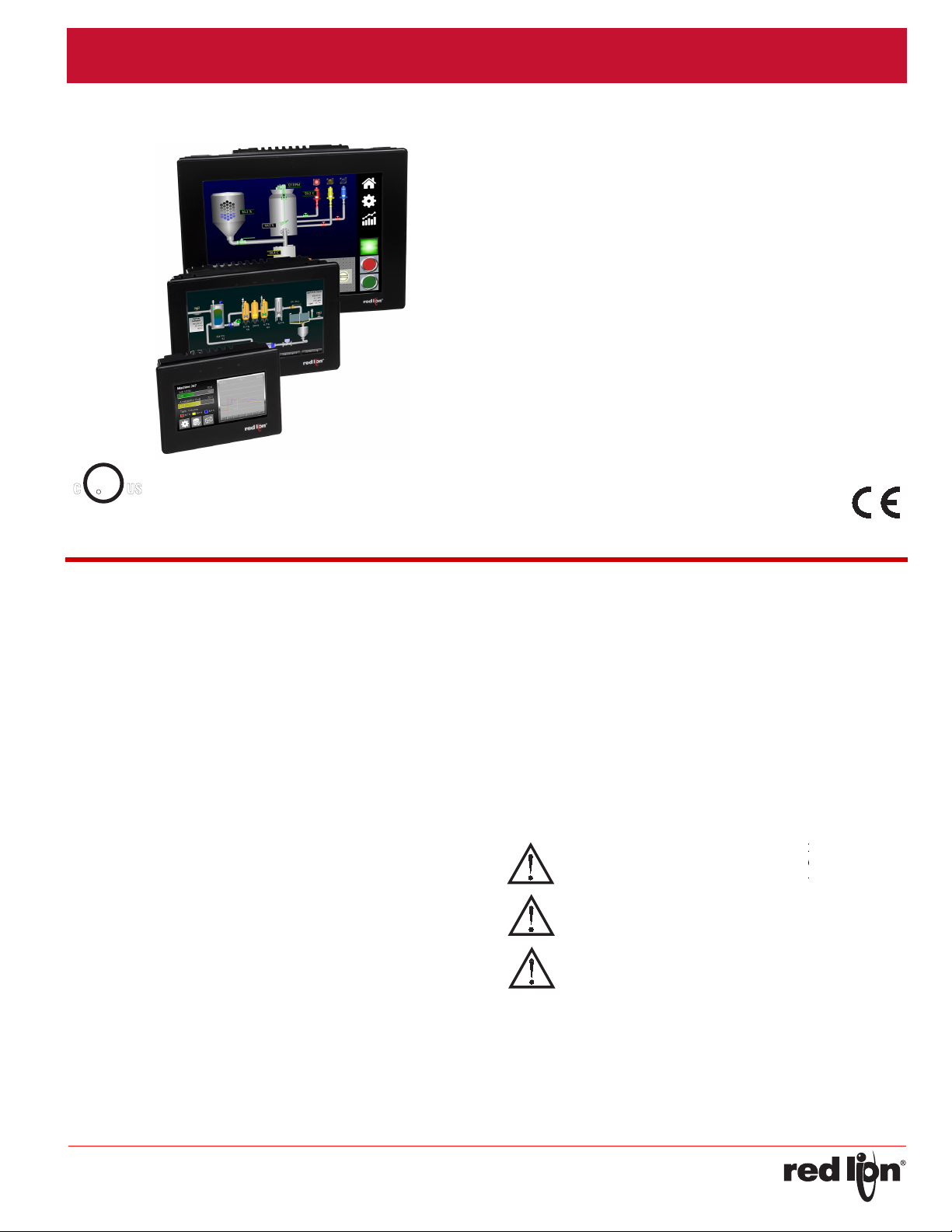
ModelCR3000‐IndustrialOperat orInterfaceWithTFTDisplay
WARNING - EXPLOSION HAZARD - DO NOT D
EQUIPMENT UNLESS POWER HAS BEEN SW
OR AREA IS KNOWN TO BE NON-HAZARDOU
CAUTION: Risk of Danger.
Read complete instructions prior to installation
and operation of the unit.
WARNING - EXPLOSION HAZARD - DO NOT DISCONNECT
EQUIPMENT UNLESS POWER HAS BEEN SWITCHED OFF
OR AREA IS KNOWN TO BE NON-HAZARDOUS.
WARNING - EXPLOSION HAZARD - DO NOT DISCONNECT
EQUIPMENT UNLESS POWER HAS BEEN SWITCHED OFF
OR AREA IS KNOWN TO BE NON-HAZARDOUS.
WARNING - EXPLOSION HAZARD - SUBSTITUTION OF
COMPONENTS MAY IMPAIR SUITABILITY FOR CLASS I,
DIVISION 2.
FOR USE IN HAZARDOUS LOCATIONS:
Class I, Division 2, Groups A, B, C, and D
C
US
U
L
R
LISTED
IND.CONT. EQ.
E317425
T4
GENERALDESCRIPTION
The CR3000 is the perfect solution for applications that require the
operator to monitor and control more than just a single device. With up to
four serial ports and two Ethernet ports, these HMI displays can connect
to multiple serial and Ethernet devices simultaneously, including PLCs,
motor drives, bar code scanners, etc.
The CR3000 performs the functions of a multiple protocol converter,
using up to four high-speed serial communications ports and one or two
10/100 Base-TX Ethernet ports. Ethernet port(s) support up to ten
protocols simultaneously, allowing dissimilar Ethernet based products to
communicate with one another. The SD card slot can be used to collect
your trending and datalogging information as well as load the unit's
configuration file, allowing configuration changes to be made and saved
to the card for later transfer.
The CR3000 range of HMIs is programmed with Red Lion's Crimson
3.1 software. Crimson offers easy to use drag and drop communications
configuration, while the embedded image library allows
to create intuitive screens and prompts for the operator. The Crimson
software is available as a no charge download from Red Lion’s website.
the programmer
• CONFIGURED USING CRIMSON
®
3.1 SOFTWARE
• THREE OR FOUR ISOLATED SERIAL COMMUNICATION PORTS,
(2 RS-232 and 1 or 2 RS-422/485) - MODEL DEPENDENT
• ONE OR TWO 10 BASE T/100 BASE-TX ETHERNET PORTS
COMMUNICATE WITH UP TO TEN PROTOCOLS
SIMUL
TANEOUSLY
• ACCEPTS ONE EXPANSION COMMUNICATION MODULE TO ADD
CANOPEN, J1939, PROFIBUS, DEVICENET AND MORE
• ONE USB DEVICE PORT TO LOAD THE UNIT’S CONFIGURATION
OR TRANSFER DATA TO AND FROM A PC
• SD CARD SOCKET FOR LOADING DATABASE IN THE FIELD
• INDUSTRIAL TFT LCD COLOR DISPLAY
• NEMA 4X/IP66 FRONT PANEL
• THREE FRONT PANEL LED INDICATORS
• POWER UNIT FROM 10-30 VDC SUPPLY
• RESISTIVE ANALOG TOUCHSCREEN
CONTENTSOFPACKAGE
- CR3000 Operator Interface
-
dware packet and plate for mounting unit into panel
Har
-
Ter
minal block for connecting power
Panel gasket
-
SAFETYSUMMARY
All safety related regulations, local codes and instructions that appear
in the manual or on equipment must be observed to ensure personal
safety and to prevent damage to either the instrument or equipment
connected to it. If equipment is used in a manner not specified by the
manufacturer, the protection provided by the equipment may be
impaired.
Do not use the unit to directly command motors, valves, or other
actuators not equipped with safeguards. To do so can be potentially
harmful to persons or equipment in the event of a fault to the unit.
-1-
Page 2
Bulletin No. CR3000-A Effective 2018-03-26
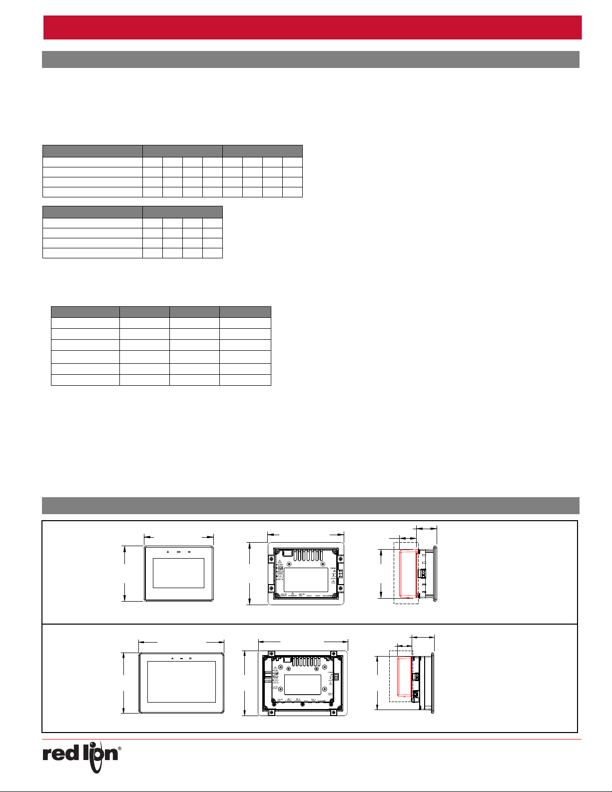
4 inch
4.12
(104.69)
5.14 (130.65)
4.62
(117.48)
5.65 (143.51)
3.62
(92.08)
1.50 (38.1)
THIS VIEW SHOWN WITH
MOUNTING PLATE AND BRACKETS
1.26 (32)
Module sold
separately
CR300004
7 inch
5.43
(138.02)
7.63 (193.98)
5.80
(147.32)
8.00 (203.2)
4.80
(121.92)
THIS VIEW SHOWN WITH
MOUNTING PLATE AND BRACKETS
2.00 (50.8)
1.26 (32)
Module sold
separately
CR300007
Drawing No. LP1042
SPECIFICATIONS
1. POWER REQUIREMENTS:
Must use a Class 2 circuit according to National Electrical Code (NEC),
NFPA-70 or Canadian Electrical Code (CEC), Part I, C22.1 or a
Limited Power Supply (LPS) according to IEC 60950-1 or Limitedenergy circuit according to IEC 61010-1.
Power connection via removable three position terminal block.
Supply Voltage: 10 to 30 VDC, Class 2 source
Input Voltage (Volts) 10V 12V 24V 30V 10V 12V 24V 30V
Typ. Power HMI only (Watts) 5.5 6.0 6.0 6.0 9.0 9.0 9.0 9.0
Max Power HMI only (Watts) 7.0 7.5 7.5 7.5 12.5 12.0 12.5 12.5
Max Power HMI w/Module (W) 12.0 13.0 13.0 13.0 17.5 17.5 18.0 18.0
Input Voltage (Volts) 10V 12V 24V 30V
Typ. Power HMI only (Watts) 12.5 12.0 12.0 12.5
Max Power HMI only (Watts) 16.5 16.0 16.0 16.5
Max Power HMI w/Module (W) 21.0 21.0 21.5 22.0
TTERY: Lithium coin cell. Typical lifetime of 5 years, nominal.
2. BA
MODEL 4.3-INCH 7-INCH
MODEL 10.4-INCH
To maintain UL rating, replacement battery must be: Red Lion CRA000
BT3V0 00000, Rayovac BR1225X-BA or Panasonic BR1225A/BN.
3. L
CD DISPLAY:.
4.3-INCH 7-INCH 10.4-INCH
Type TFT TFT TFT
Colors 16M 16M 16M
Pixels 480 x 272 800 X 480 800 X 600
Brightness
Backlight Type LED LED LED
Backlight Life 30K HR TYP. 50K HR TYP. 50K HR TYP.
4. TOUC
HSCREEN: Four-wire resistive analog
500 cd/m
2
430 cd/m
2
400 cd/m
2
5. MEMORY:
On Board
User Memory: 1 Gbyte of non-volatile Flash memory.
Memory Card: SD slot accepts standard capacity cards.
6. COMMUN
USB Devi
ICATION CAPABILITIES
ce Port: Isolated and adheres to USB specification 2.0 (high
speed, full speed) only using Type B connection.
IS FOR SYSTEM SET-UP AND DIAGNOSTICS AND IS NOT INTENDED
FOR PERMANENT CONNECTION.
:
USB DEVICE PORT
USB Host Ports: Comply with Universal Serial Bus Specification Rev
2.0. Support data transfers at (high speed, full speed). Hardware
over current protected (0.5 A max per port).
Serial Ports: Ports are individually isolated. Format and Baud Rates for
each port are individually software programmable up to 115,200
baud.
Port to Port Isolation: 1500 Vrms for 1 minute.
Signal Isolation: 500 V.
Ethernet Ports: 10 BASE-T / 100 BASE-TX
RJ45 jacks are wired as a NIC (Network Interface Card).
Isolation from Ethernet network to operator interface: 1500 Vrms
7. ENVIRONMENT
AL CONDITIONS:
Operating Temperature Range: -10 to 50 °C
Storage Temperature Range: -20 to 70 °C
Vibration to IEC 68-2-6: Operational 5-500 Hz, 2 g
Shock to IEC 68-2-27: Operational 30 g
Operating and Storage Humidity: 0 to 85% max. RH non-condensing
Altitude: Up to 2000 meters
Installation Category II, Pollution Degree 2 as defined in IEC/EN 60664-1.
8. CERTIFICATIONS AND COMPLIANCES:
CE Approved
EN 61326-1 Immunity to Industrial Locations
Emission CISPR 11 Class A
IEC/EN 61010-1
RoHS Compliant
UL Hazardous: File #E317425
Type 4X Indoor / IP66 Enclosure rating (Face only)
9. CONNEC
TIONS: High compression cage-clamp terminal block
Wire Strip Length: 0.3" (7.5 mm)
2
Wire Gage Capacity: 12 to 24 AWG (3.31 to 0.20 mm
) copper wire
Torque: 4.4-5.3 inch-lbs (0.5-0.6 N-m)
10. CONST
RUCTION: Polycarbonate enclosure with Type 4X/IP66 rating
when correctly fitted per the mounting instructions provided.
Protection against mechanical impact up to 5 Joule, IK08 per IEC 62262.
11. MOUNTING REQUIREMENTS: Maximum panel thickness is 0.25"
(6.35 mm) with included stiffener plate, or 0.375" (9.53 mm) without
plate. For NEMA 4X / IP66 sealing, the stiffener plate and a panel with
a minimum thickness of 0.06" (1.52 mm) is reco
Mounting Scr
ew Torque: 4.0 lbf-in (0.45 Nm). CAUTION: DO NOT
mmended.
OVERTIGHTEN THE CLAMPS
12. WEIGHT: U
nit weight with stiffener plate and clips
CR3000 04: 1.00 lb (454 g)
CR3000 07: 2.01 lb (913 g)
CR3000 10: 3.16 lb (1.435 Kg)
DIMENSIONSINinches(mm)
-2-
Page 3
Released 2016-xx-xx Bulletin No. CR3000-A
10.4 inch
10.78 (273.73)
11.14 (282.96)
8.87
(225.29)
8.50
(215.99)
7.87
(199.9)
2.00 (50.8)
THIS VIEW SHOWN
WITH MOUNTING PLATE
AND BRACKETS
separately
Module sold
1.26 (32)
CR300010
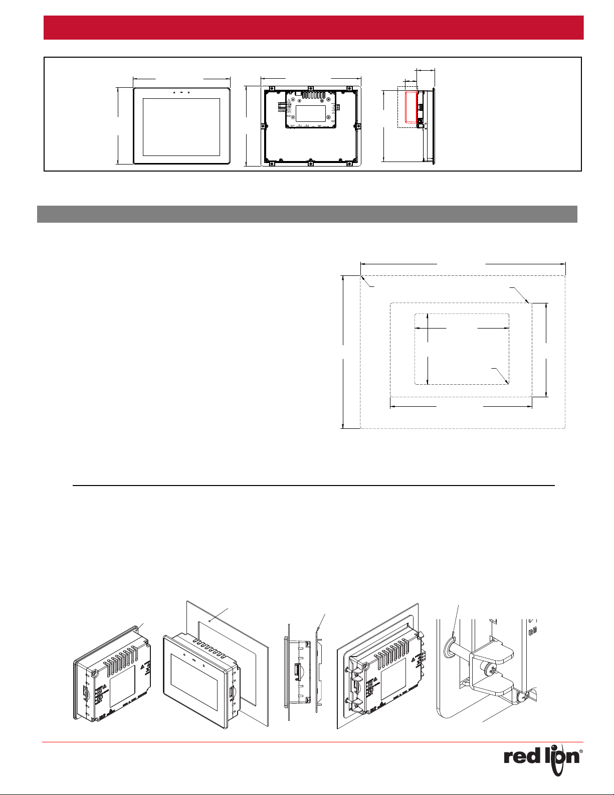
10.4 INCH PANEL CUT-OUT
4 INCH PANEL CUT-OUT
7 INCH PANEL CUT-OUT
Must meet hole tolerance specification for
full NEMA 4X and IP66 ingress protection.
4.69
(119.13)
3.66
(92.96)
4.87
(123.7)
7.93
(201.42)
10.20 (259.08)
7.06 (179.32)
R
0.10
(2.54)
R
0.08
(2.03)
R
0.10
(2.54)
ALL TOLERANCES +/-0.03" (+/-0.762 mm)
1
2
3
4
5
GASKET
MOUNTING
SURFACE
STIFFENER
PLATE
SCREW ANTI-WALK
FEATURE
Drawing No. LP1042
INSTALLINGANDPOWERINGTHECR3000
MOUNTINGINSTRUCTIONS
This operator interface is designed for through-panel mounting. The
panel can be VESA mounted with the addition of a VESA mount adapter
plate. This plate allows mounting to a standard 75 x 75 mm VESA bracket.
The mounting surface should have a minimum thickness of 0.06" (1.53
mm)
and maximum thickness
per the dimensions shown in the diagram. Care should be taken to
remove any loose material from the mounting cut-out to prevent that
material from falling into the operator interface during installati
Cau
tion: Only the screws provided with the VESA adapter plate should be
used to mount the CR3000. Unit cannot be VESA mounted if an
expansion module will be used.
For hazardous location installation the following shall be taken into
consideration:
- T
his device is open-type and must be mounted in a suitable dust-tight
end-enclosure in accordance with articles 500 and 502 of the NEC
and positioned so only the face of the display is exposed.
- Must be wired using Division 2 wiring methods as specified in article
501-4(b), 502-4(b), and 503-3(b) of the National Electric Code, NFPA
70 for installation within the United States, or as specified in section
19-152 of Canadian Electrical Code for installation in Canada.
- Combinations of equipment in your system are subject to investigation
by the local Authority having jurisdiction at the time of installation.
of 0.375" (9.53 mm). Cut the mounting hole
on.
Follow these steps to install the unit.
1. Make sure the bezel gasket is properly in place.
2.Place the unit into the fr
3
4. Insert clamps into the slots provided on the sides (CR300004) or top
5
ont of the panel cutout
.
. Install stiffener plate over unit on the inside of the panel. This ensures
the mounting surface is stiff enough for a proper seal. The plate is
required to meet NEMA 4X and IP66.
and bottom (CR300007 and CR300010) of
the unit.
. Make sure the clamp’s screw sits in the “U” shaped feature. This will
prevent the screw from “walking”. Tighten the clamping screws in an
-3-
even pattern until the unit is secured in the panel. To seal to Type 4X/
IP66 specifications, all supplied mounting clamps must be used and be
torqued to 4.0 lbf-in (0.45 Nm). CAUTION: DO NOT OVERTIGHTEN
THE CLAMPS. The panel must not flex more than 0.010" for proper
sealing. The safety of any system incorporating the equipment is the
responsibility of the assembler of the system.
Page 4

Bulletin No. CR3000-A Effective 2018-03-26
REMOVE
MODULE PLUG
WARNING: Disconnect all power
to the unit before installing or
removing modules.
Drawing No. LP1042
CONNECTING POWER
The CR3000 requires a 10-30 VDC
power supply. A pluggable power block is
provided to connect the 24 VDC. There are
three screw terminals. Strip and connect
the wire according to the terminal block
specifications on Page 2. Connect the
positive lead to the plus (+) screw and the
negative lead to the minus (-) screw.
Please take care to observe the following points:
Mount the power supply close to the unit, with usually not more than
–
6 feet (1.8 m) of cable between the supply and the operator
interface. Ideally, the shortest length possible should be used.
–
The wire used to connect the operator interface’s power supply
should be at least 22-gage wire suitably rated for the temperatures
of the environment to which it is being installed. If a longer cable run
is used, a heavier gage wire should be used. The routing of the
cable should be kept away from large contactors, inverters, and
other devices which may generate significant electrical noise.
– A power supply with an NEC Class 2 or Limited Power Source (LPS)
and SELV rating is to be used. This type of power supply provides
isolation to accessible circuits from hazardous voltage levels generated
by a mains power supply due to single faults. SELV is an acronym for
“safety extra-low voltage.” Safety extra-low voltage circuits shall exhibit
voltages safe to touch both under normal operating conditions and after
a single fault, such as a breakdown of a layer of basic insulation or after
the failure of a single component has occurred. A suitable disconnect
device shall be provided by the end user.
CONNECTING TO EARTH GROUND
Each operator panel has a chassis ground terminal on the back of the
unit. Your unit should be connected to earth ground. Steps should be
taken beyond connecting to earth ground to eliminate the buildup of
electrostatic charges.
The chassis ground is not connected to signal common of the unit.
Maintaining isolation between earth ground and signal common is not
required to operate your unit. But, other equipment connected to this unit
may require isolation between signal common and earth ground. To
maintain isolation between signal common and earth ground care must
be taken when connections are made to the unit. For example, a power
supply with isolation between its signal common and earth ground must
be used. Also, plugging in a USB cable may connect signal common and
earth ground.
1
USB’s shield may be connected to earth ground at the host. USB’s
shield in turn may also be connected to signal common.
1
MODULEINSTALLATION
Remove module plug and attach module to CR3000. Torque screws to
6.0 pound-force inch [96 ounce-force inch] (0.68 Nm).
EMCINSTALLATIONGUIDELINES
Although Red Lion Controls products are designed with a high degree
of immunity to Electromagnetic Interference (EMI), proper installation and
wiring methods must be followed to ensure compatibility in each
application. The type of the electrical noise, source or coupling method
into a unit may be different for various installations. Cable length, routing,
and shield termination are very important and can mean the difference
between a successful or troublesome installation. Listed are some EMI
guidelines for a successful installation in an industrial environment.
1. A unit should be mounted in a metal enclosure, which is properly
connected to protective earth.
2. Use shielded cables for all Signal and Control inputs. The shield
connection should be made as short as possible. The connection point
for the shield depends somewhat upon the application. Listed below
are the recommended methods of connecting the shield, in order of
their effectiveness.
a.
Connect the shield to earth ground (protective earth) at one end
where the unit is mounted.
nect the shield to earth ground at both ends of the cable, usually
b. Con
when the noise source frequency is over 1 MHz.
3.
Never run Signal or Control cables in the same conduit or raceway with
AC power lines, conductors, feeding motors, solenoids, SCR controls,
and heaters, etc. The cables should be run through metal conduit that
is properly grounded. This is especially useful in applications where
cable runs are long and portable two-way radios are used in close
proximity or if the installation is near a commercial radio transmitter.
Also, Signal or Control cables within an enclosure should be routed as
far away as possible from contactors, control relays, transformers, and
other
noisy components.
4. Long cable runs are more susceptible to EMI pickup than short cable runs.
5. In extremely high EMI environments, the use of external EMI
suppression devices such as Ferrite Suppression Cores for signal and
control cables is effective. The following EMI suppression devices (or
equivalent) are recommended:
Fair-Rite part number 0443167251 (Red Lion Controls #FCOR0000)
Line Filters for input power cables:
Schaffner # FN2010-1/07 (Red Lion Controls #LFIL0000)
6.
To protect relay contacts that control inductive loads and to minimize
radiated and conducted noise (EMI), some type of contact protection
network is normally installed across the load, the contacts or both. The
most effective location is across the load.
a. Usin
g a snubber, which is a resistor-capacitor (RC) network or metal
oxide varistor (MOV) across an AC inductive load is very effective at
reducing EMI and increasing relay contact life.
b. If a DC inductive load
transistor switch, care must be taken not to exceed the breakdown
voltage of the transistor when the load is switched. One of the most
effective ways is to place a diode across the inductive load. Most
Red Lion products with solid state outputs have internal zener diode
protection. However external diode protection at the load is always a
good design practice to limit EMI. Although the use of a snubber or
varistor could be used.
Red Lion part numbers: Snubber: SNUB0000
are should be taken when connecting input and output devices to the
7. C
(such as a DC relay coil) is controlled by a
Varistor: ILS11500 or ILS23000
-4-
Page 5

Released 2016-xx-xx Bulletin No. CR3000-A
RS232 RS485 RS232 (PGM)
USB
DEVICE ETHERNET
USB
HOST
RS232 RS485/422
RS232 (PGM)
COMM
COMM
COMM
COMM
COMM
TxA (PIN 8)
TxB (PIN 1)
RTS (PIN 6)
CTS (PIN 1)
CTS (PIN 1)
RTS (PIN 6)
RxA
RxB
TxB
TxENTxTxA
Rx
Tx
Rx
ETHERNET
(NIC)
USB
TYPE B
USB
TYPE A
CR3000 04 PORT PIN OUTS
RS232
RS485
PORT A
RS232 (PGM)
COMM
COMM
COMM
COMM
COMM
TxA (PIN 8)
TxB (PIN 1)
RTS (PIN 6)
CTS (PIN 1)
CTS (PIN 1)
RTS (PIN 6)
RxA
RxB
TxB
TxENTxTxA
RS485
PORT B
COMM
TxA (PIN 8)
TxB (PIN 1)
RxA
RxB
TxB
TxEN
TxA
Rx
Tx
Rx
1
ETHERNET
(NIC)
2
ETHERNET
(NIC)
USB
TYPE B
RS232
PORT A
RS485 RS232 (PGM)
USB
DEVICE
2
ETHERNET
USB
HOST
PORT B
RS485
1
ETHERNET
DUAL USB
TYPE A
CR3000 07/10 PORT PIN OUTS
WARNING - DO NOT CONNECT OR DISCONNECT CABLES
WHILE POWER IS APPLIED UNLESS AREA IS KNOWN TO BE
NON-HAZARDOUS. USB DEVICE PORT IS FOR SYSTEM SET-UP
AND DIAGNOSTICS AND IS NOT INTENDED FOR PERMANENT
CONNECTION.
Drawing No. LP1042
COMMUNICATINGWITHTHECR3000
CONFIGURINGACR3000
The CR3000 is configured using Crimson® 3.1 software. Crimson is
available as a no charge download from Red Lion’s website. Crimson
updates for new features and drivers are posted on the website as they
become available. By configuring the CR3000 using the latest Crimson
version, you are assured that your unit has the most up to date feature
set. Crimson software can configure the CR3000 through the RS232
PGM port, USB port, ethernet port or SD card.
The CR3000 has three or four serial ports, a USB device port, one or
two USB Host ports, and an Ethernet port as shown below.
The serial ports are available via RJ connectors. There are two RS232
ports. The port labeled RS232 (PGM) can be used as a Programming
Port or you can assign a protocol to it. The RS485 ports can be used for
both RS485 or 422 communications. All of the serial ports are isolated.
Note: If you assign a protocol to the Programming Port, you will no
longer be able to download to that port. You should create a means
to call the StopSystem() function from the HMI touchscreen, such
that the Programming Port activity can be halted on command.
Alternatively, the HMI's memory can be cleared to restore download
functionality.
Ethernet port(s) can be programmed to communicate via ten protocols
simultaneously. For more information on protocol support, please refer to
the Crimson 3.1 programming software.
The USB device port is a standard device port with a Type B connector,
and is used as the programming port. The driver needed to use the USB
port will be installed with
The USB host port(s) are standard host ports with Type A connector(s)
and can be used to interface to USB enabled peripherals. These ports
supply 5 V power per the USB standard.
The SD card can be used to program a CR3000 by placing an image
file on the SD card. The card is then inserted into the target CR3000 and
powered. Refer to the Crimson literature for more information on the
proper names and locations of this file.
Crimson.
USB,DA TATRANSFERSFROMTHESDCARD
In order to transfer data from the SD card via the USB port, a driver
must be installed on your computer. This driver is installed with Crimson
and is located in the folder C:\Program Files\Red Lion Controls\Crimson
3.1\Device\ after Crimson is installed. This may have already been
accomplished if your CR3000 was configured using the USB port.
Once the driver is installed, connect the CR3000 to your PC with a
USB cable, and follow “Mounting the SD” instructions in the Crimson 3.1
user manual.
INSERTION/REMOVALOFTHESDCARD
Insert the SD card into the slot provided with the card oriented as shown.
The card is inserted properly when the end of the card is flush with the
CR3000 case. To remove the SD card, push in slightly on the card.
CABLESANDDRIVERS
Red Lion has a wide range of cables and drivers for use with many
different communication types. A list of these drivers and cables along
with pin outs is available from Red Lion’s website. New cables and
drivers are added on a regular basis. If making your own cable, refer to
the “Port Pin Outs” that corresponds to your specific model for wiring
information.
ETHERNETCOMMUNICATIONS
Ethernet communications can be established at either 10 BASE-T or
100 BASE-TX. The unit’s RJ45 jack is wired as a NIC (Network Interface
Card). It auto-detects remote transmit and receive pairs and correctly
assigns the transmit and receive pairs. This feature enables the user to
use whichever type of cable (cross-over or straight) is available.
The Ethernet connector contains two LEDs that represent the following
statuses:
LED COLOR DESCRIPTION
YELLOW solid Link established.
YELLOW flashing Data being transferred.
GREEN (OFF) 10 BASE-T Communications
GREEN (ON) 100 BASE-TX Communications
On the rear of each unit is a unique 12-digit MAC address. Refer to the
Crimson manual and Red Lion’s website for additional information on
Ethernet communications.
-5-
Page 6

Bulletin No. CR3000-A Effective 2018-03-26
TX
5V
8
1
7
2
TxB
TxA
130K
130K
5
TxEN (OC)
RX
130K
5V
130K
RxB
4
RxA
3
COMM
6
RS485/422 4-WIRE
CONNECTIONS
RS485 2-WIRE
CONNECTIONS
TxEN (OC)
TX/RX
130K
5
TxA
2
8
130K
5V
7
1
TxB
6 COMM
CR3000 TO MODULAR
CONTROLLER
HMI Name
Modular
Controller
Name
1,4 TxB 1,4 TxB
4,1 RxB 4,1 RxB
2,3 TxA 2,3 TxA
3,2 RxA 3,2 RxA
5TxEN 5 TxEN
6COMM 6 COMM
7TxB 7 TxB
8TxA 8 TxA
Drawing No. LP1042
RS232PORTS
The CR3
serial ports. Although only one
of these ports can be used for
programming, both ports can
be used for communications
with a PLC. The serial ports
can be used for either master
or slave protocols with any
CR3000 configuration. Each
serial port has a pair of LEDs
to indicate transmit and receive
activity. The pinouts are shown
to the right.
000 has two RS232
CR3000 RS232 TO A PC
HMI: RJ12 Name PC: DB9 Name
4 COMM 1 DCD
5Tx2Rx
2Rx3Tx
N/C 4 DTR
3 COMM 5 GND
N/C 6 DSR
1 CTS 7 RTS
6 RTS 8 CTS
N/C 9 RI
RS485/422COMMSPORT
The RS485 port (s) of the CR3000 can be used for RS485 or RS422
communication. There is a separate RJ connector for each option. Each
serial port has a pair of LEDs to indicate transmit and receive activity.
ExamplesofRS4852‐WireConnections
CR3000 TO RED LION RJ11
HMI:RJ45 Name RLC:RJ11 Name
5TxEN 2 TxEN
6COMM 3 COMM
1TxB 5 B-
2TxA 4 A+
DH485COMMUNICATIONS
The CR3000’s RS485/422 COMMS port can also be used for Allen
Bradley DH485 communications.
WARNING: DO NOT use a standard DH485 cable to connect this port to
Note: All Red Lion devices connect A to A and B to B. Refer to
edlion.net for additional information.
www.r
-6-
Page 7

Released 2016-xx-xx Bulletin No. CR3000-A
WARNING - EXPLOSION HAZARD - DISCONNECT POWER AND
ENSURE THE AREAS IS KNOWN TO BE NON-HAZARDOUS
BEFORE SERVICING/REPLACING THE UNIT AND BEFORE
INSTALLING OR REMOVING I/O WIRING AND BATTERY.
To maintain UL rating, battery must
be replaced with one listed in the
Specifications.
Drawing No. LP1042
SOFTWARE/UNITOPERATION
CRIMSON®SOFTWA RE
Crimson software is available as a no charge download from Red
Lion’s website. The latest version of the software is always available from
the website, and updating your copy is free.
DISPLAY
This operator interface uses a liquid crystal display (LCD) for
displaying text and graphics. The display utilizes an LED backlight for
lighting the display. The backlight can be dimmed for low light conditions.
The LED backlight has a limited lifetime. Backlight lifetime is based
upon the amount of time the display is turned on at full intensity. Turning
the backlight off when the display is not in use can extend the lifetime of
your backlight. This can be accomplished through the Crimson software
when configuring your unit.
FRONTPAN E LLEDS
There are three front panel LEDs that can be configured using
Crimson. Shown below is the default status of the LEDs.
LED INDICATION
GREEN (▲)
STEADY Unit is powered.
BLUE (▬)
FLASHING
OFF No SD card is present.
STEADY Valid SD card present.
FLASHING RAPIDLY SD card being checked.
FLICKERING SD card accessed.
FLASHING SLOWLY Incorrectly formatted SD card present.
RED (■)
FLASHING Data tag is in an alarm active state.
STEADY Data tag is in an alarm accepted state.
Unit is in the boot loader
A battery is used to keep time when the unit is without power. The
battery of a CR3000 unit does not affect the unit’s memory, all
configurations and data is stored in non-volatile memory.
ChangingtheBattery
To change the battery of a CR3000, first remove power to the unit.
Remove the SD card if one is installed. Insert a small screwdriver into the
slot provided on the battery holder and pry the battery holder with battery
out of the unit. Remove the old battery from the plastic holder and replace
it with a new battery. Make sure the orientation of the battery is correct
and as shown in the diagram.
Re-install the battery holder with battery into the CR3000 unit. Using
Crimson or the unit’s keypad, enter the correct time and date.
TOUCHSCREEN
This operator interface utilizes a resistive analog touchscreen for user
input. The unit will only produce an audible tone (beep) when a touch on
an active touchscreen cell is sensed. The touchscreen is fully functional
as soon as the operator interface is initialized, and can be operated with
gloved hands.
CAUTION: Lithium battery. Danger of explosion if battery is
incorrectly replaced. Replace only with the same or equivalent
type recommended by the manufacturer.
Please note that the old battery must be disposed of in a
manner that complies with your local waste regulations. The
battery must not be disposed of in fire, or in a manner whereby
it may be damaged and its contents could come into contact
with human skin.
-7-
Page 8

Bulletin No. CR3000-A Effective 2018-03-26
Drawing No. LP1042
TRADEMARKACKNOWLEDGMENTS
Ethernet is a registered trademark of Xerox Corporation.
All other company and product names are trademarks of their
respective owners.
ORDERINGINFORMATION
MODEL NO. DESCRIPTION PART NUMBER
4.3" HMI with 3 Serial, 1 Ethernet, and 1 USB Host Ports CR3000 04000 00310
CR3000
CRM000
SD
CBL
FILM
CRA000
1
Contact your Red Lion distributor or visit our website for selection of Expansion modules, SD
7.0" HMI with 4 Serial, 2 Ethernet, and 2 USB Host Ports CR3000 07000 00420
10.4" HMI with 4 Serial, 2 Ethernet, and 2 USB Host Ports CR3000 10000 00420
Expansion Modules
1
SD Card
Communications Cables and Adapter
Protective Film for CR3000 04xxx xxxxx G3FILM4K
Protective Film for CR3000 07xxx xxxxx G0FILM07
Protective Film for CR3000 10xxx xxxxx G0FILM10
Adapter Plate - Kadet 7 to CRx000 07 CRA000 AD070 70000
Adapter Plate - G306 to CRx000 07 CRA000 AD060 70000
Adapter Plate - G308 to CRx000 07 CRA000 AD080 70000
Adapter Plate - G310 to CRx000 10 CRA000 AD101 00000
VESA Mount Adapter Plate CRA000 ADVESA 0000
Replacement Battery CRA000 BT3V0 00000
1
1
CRM0000 xxxxx xxxxx
SDxxxxxx
CBLxxxxx
cards, adapters and cables.
-8-
 Loading...