

Page 1
THE 1/16 DIN COUNTERS
MODEL C48C INSTRUCTION MANUAL
Page 2

INTRODUCTION
The C48 Counters (C48C) are a multi-purpose series of industrial control
products that are field-programmable for solving various applications. This
series of products is built around the concept that the end user has the capability to program different personalities and functions into the unit in order to
adapt to different indication and control requirements.
The C48C unit, which you have purchased, has the same high quality workmanship and advanced technological capabilities that have made Red Lion
Controls the leader in today’s industrial market.
Red Lion Controls has a complete line of industrial indication and control
equipment, and we look forward to servicing you now and in the future.
CAUTION:
Read complete instructions prior to
installation and operation of the unit.
CAUTION:
Risk of electric shock.
UL Recognized Component,
File # E137808
Page 3

TABLE OF CONTENTS
GENERAL DESCRIPTION.............................................................................................................................................................1
Safety Summary.......................................................................................................................................................................1
Block Diagram ..........................................................................................................................................................................2
INSTALLATION & CONNECTIONS...............................................................................................................................................3
Multiple Unit Stacking ..............................................................................................................................................................3
Mounting Instructions ...............................................................................................................................................................4
Unit Removal Procedure ..........................................................................................................................................................4
Removing Unit Assembly ........................................................................................................................................................4
Installing Unit Assembly ...........................................................................................................................................................5
Output Board ...........................................................................................................................................................................5
Replacing Relay Output Board .........................................................................................................................................5
EMC Installation Guidelines ....................................................................................................................................................6
Wiring Connections .................................................................................................................................................................6
AC Versions (C48XX0X)....................................................................................................................................................7
DC Versions (C48CXX1X) .................................................................................................................................................7
Serial Communication Wiring ...................................................................................................................................................8
User Inputs ...............................................................................................................................................................................8
Output Wiring ...........................................................................................................................................................................8
Input A and Input/User B..........................................................................................................................................................8
Various Sensor Output Connections ......................................................................................................................................10
FRONT PANEL DESCRIPTION .................................................................................................................................................11
Keypad Functions ...................................................................................................................................................................11
BASIC OPERATION.....................................................................................................................................................................12
Single and Dual Preset Units.................................................................................................................................................12
3 Preset Batch Unit ................................................................................................................................................................12
Normal Operating Mode .........................................................................................................................................................12
Modifying A Secondary Display Parameter From the Front Panel ........................................................................................12
Protected Value Menu ...........................................................................................................................................................13
Front Panel Accessible Functions With Program Disable ....................................................................................................14
PROGRAMMING GENERAL DESCRIPTION .............................................................................................................................15
Programming Option Values ..................................................................................................................................................15
Programming Numeric Data Values.......................................................................................................................................15
Digit Entry ........................................................................................................................................................................15
-i-
Page 4

TABLE OF CONTENTS (Cont’d)
Auto Scrolling...................................................................................................................................................................15
Saving Program ...............................................................................................................................................................15
USER INTERFACE/PROGRAMMING MODES ...........................................................................................................................16
Programming Menu................................................................................................................................................................16
Numeric Value entry method ...........................................................................................................................................16
Access Prescaler Value ...................................................................................................................................................16
Prescaler (0.00001 - 9.99999*) .......................................................................................................................................16
Decimal Point Position .....................................................................................................................................................17
Count Input Mode ............................................................................................................................................................17
Count Modes .............................................................................................................................................................17
Counter (1) Operating Mode............................................................................................................................................18
Counter 2 Assignment (Batch Model only)......................................................................................................................20
Counter 2 Operating Mode (Batch Model only)...............................................................................................................21
Access Preset Values ......................................................................................................................................................22
Preset 1 Value .................................................................................................................................................................22
Preset 2 Value (Dual Preset/Batch Models only) ............................................................................................................22
Preset 3 Value (Batch Model only) ..................................................................................................................................22
Preset 1 Track Preset 2 (Dual Preset/Batch Models only) ..............................................................................................22
Access Output Time Values.............................................................................................................................................23
Output Resolution ............................................................................................................................................................23
Output 1 Time Value ........................................................................................................................................................23
Output 2 Time Value (Dual Preset/Batch Models only) ...................................................................................................23
Output 3 Time Value (Batch Model only) .........................................................................................................................23
Reverse Output Logic ......................................................................................................................................................23
Reverse Annunciator Logic..............................................................................................................................................24
Output Power-Up State....................................................................................................................................................24
User Inputs ......................................................................................................................................................................24
User Input 1 .....................................................................................................................................................................25
User Input 2 ....................................................................................................................................................................25
User Input B .....................................................................................................................................................................25
User F1 Key .....................................................................................................................................................................25
Programming / Protected Parameter Menu Code Value (0-199) ....................................................................................25
Scroll Display ...................................................................................................................................................................26
-ii-
Page 5

TABLE OF CONTENTS (Cont’d)
Serial Baud Rate and Parity Settings ..............................................................................................................................26
Serial Unit Address (00-99) .............................................................................................................................................26
Serial Abbreviate Mnemonics ..........................................................................................................................................26
Print Options ....................................................................................................................................................................27
Print and Reset Count .....................................................................................................................................................27
Prescaler Output Pulse at [Prescaler Output Model Only] .............................................................................................27
Prescaler Output Pulse Length (1-9) [Prescaler Output Model Only] .............................................................................27
Factory Settings ...............................................................................................................................................................28
Factory Settings Chart...............................................................................................................................................28
User Settings Chart ...................................................................................................................................................29
RS-485 SERIAL COMMUNICATIONS.........................................................................................................................................30
Communication Format ..........................................................................................................................................................30
Sending Commands and Data...............................................................................................................................................30
Receiving Data .......................................................................................................................................................................32
Terminal Emulation Program For IBM®PC ...........................................................................................................................33
Serial Connections .................................................................................................................................................................33
Terminal Descriptions ......................................................................................................................................................33
Connecting To A Host Terminal .......................................................................................................................................34
Troubleshooting Serial Communications................................................................................................................................35
PRESCALER OUTPUT OPTION .................................................................................................................................................36
APPENDIX “A” - APPLICATION EXAMPLE ..............................................................................................................................37
APPENDIX “B” - SPECIFICATIONS AND DIMENSIONS ..........................................................................................................39
APPENDIX “C” - TROUBLESHOOTING ....................................................................................................................................43
APPENDIX “D” - CALCULATING THE PRESCALER................................................................................................................45
APPENDIX “E” - TERMINAL CONFIGURATIONS FOR C48 COUNTERS ...............................................................................46
APPENDIX “F” - ORDERING INFORMATION............................................................................................................................48
-iii-
Page 6

Page 7

GENERAL DESCRIPTION
The Model C48 Counter is available as a Standard Counter or a Batch
Counter. The Standard Counter is available with single or dual presets. The
Batch Counter has a main process counter with dual presets and a secondary
counter with a single preset. The secondary counter can be selected to function
as a batch or a total counter.
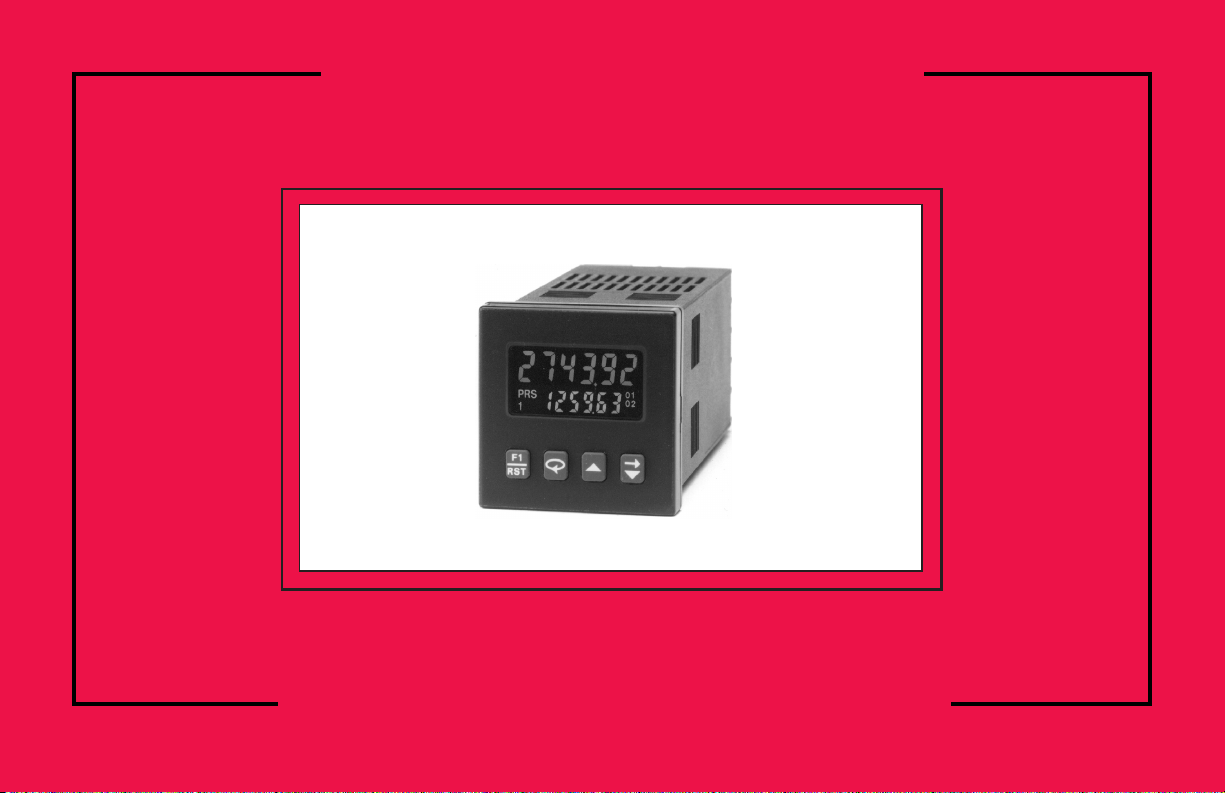
The C48C features a 7 segment, 2 line by 6 digit reflective or backlit LCD
display. For the backlit versions, the main display line is red and shows the
count value. When preset 3 or output 3 is viewed in the secondary display, the
Batch/Total value is viewed in the main display. The smaller secondary display
line is green and can be used to view the prescaler value, preset values, output
time values or Batch/Total count values (Batch model).
The C48C offers a choice of nine programmable counting modes for use in
applications requiring bi-directional, anti-coincidence, and quadrature counting.
The unit may be programmed to register counts on both edges of the input signal
providing frequency doubling capability. DIP switches are used for input
configuration set-up and to provide a Program Disable function.
Four front panel push-buttons are used for programming the operating modes
and data values, changing the viewed display, and performing user
programmable functions, i.e. reset, etc. The C48C can be configured for one of
two numeric data entry methods, digit entry or automatic scrolling. The digit
entry method allows for the selection and incrementing of digits individually.
The automatic scrolling method allows for the progressive change of one
through all digit positions by pressing and holding the “up” or “down” button.
The C48 Counter has programmable User Inputs and a programmable front
panel function key. The user inputs can be configured as sinking (active low) or
sourcing (active high) inputs via a single plug jumper. The following functions
are available for user inputs and the front panel function key.
The Program Disable DIP switch, a user-programmable code value, an
external user input (selected for Program Disable), and the Accessible value
parameters can all be utilized to provide multi-level protection against
unauthorized changes to data values and unit configuration.
The Standard Counter with Dual Presets is available with solid-state or Relay
outputs. The Single Preset model has a solid-state and relay output. The Batch
Counter has relay outputs for Output 2 and the Batch/Total Output (3), with
Output 1 available as solid-state. The Batch Counter is also available with three
solid-state outputs. For all C48 Counters, the solid-state outputs are available in
a choice of NPN current sinking or PNP current sourcing, open-collector
transistor outputs. All relay output boards are field replaceable.
A Prescaler Output model is available as a Dual Preset, with solid-state
outputs. The Prescaler Output is useful for providing a lower frequency scaled
pulse train to a PLC or another external totalizing counter. The Prescaler Output
provides an output pulse for every count, or every 10 counts registered on the
display.
Optional RS485 serial communication capabilities allow for interrogation
and modification of the preset, count, and prescaler values.
Optional programming software (SFC48) is available to program all unit
configuration parameters. The software allows unit configurations to be created,
uploaded, downloaded, and saved to a file for later use or multi-unit
programming.
The unit is constructed of a lightweight, high impact plastic case with a
textured front panel and a clear display window. The front panel meets NEMA
4X/IP65 specifications for indoor use, when properly installed. Multiple units
can be stacked horizontally or vertically. Modern surface-mount technology,
extensive testing, plus high immunity to noise interference makes the C48
Counters extremely reliable in industrial environments.
Safety Summary
All safety related regulations, local codes and instructions that appear in the
manual or on equipment must be observed to ensure personal safety and to
prevent damage to either the instrument or equipment connected to it. If
equipment is used in a manner not specified by the manufacturer, the protection
provided by the equipment may be impaired.
Do not use this unit to directly command motors, valves, or other actuators
not equipped with safeguards. To do so, can be potentially harmful to persons
or equipment in the event of a fault to the unit.
-1-
Reset Print Request
Store and Reset Change Display
Program Disable Count Inhibit
Store Reset Outputs
Page 8
-2-
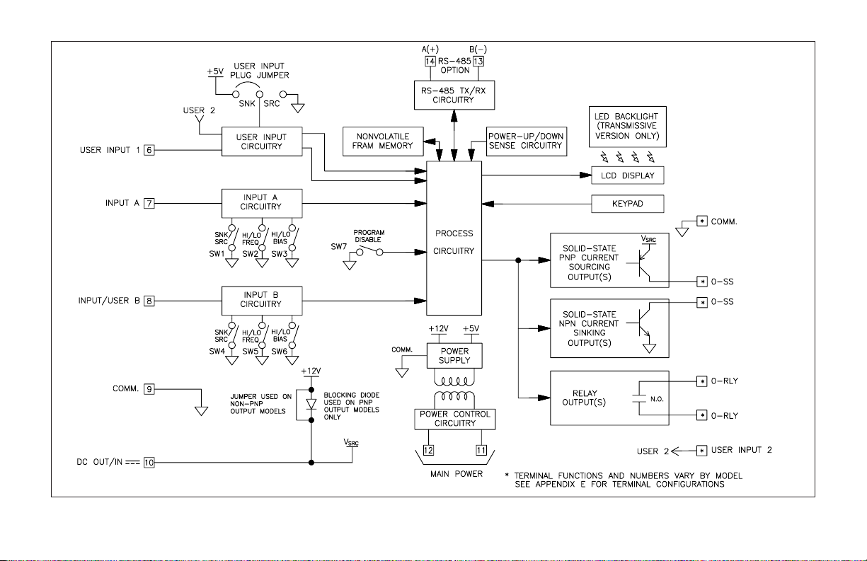
Figure 1, Block Diagram
BLOCK DIAGRAM
Page 9
INSTALLATION & CONNECTIONS
The C48 Counter meets NEMA 4X/IP65 requirements for indoor use
to provide a watertight seal in steel panels with a minimum thickness of
0.09 inch, or aluminum panels with a minimum thickness of 0.12 inch.
The units are intended to be installed into an enclosed panel. The
complete unit assembly (i.e. PC boards and bezel), MUST be in the case
when mounting the unit.
Multiple Unit Stacking
The C48C is designed for close spacing of multiple units. Units can be
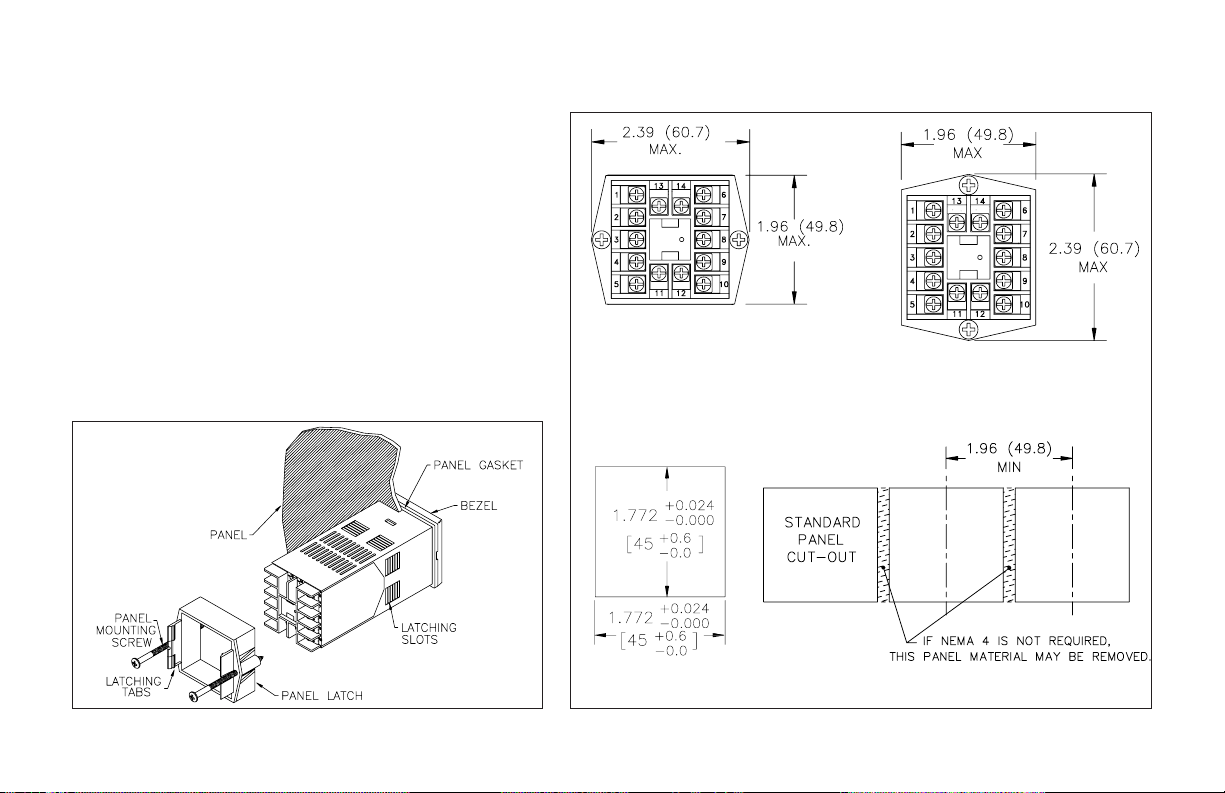
stacked either horizontally or vertically. For vertical stacking, install the
panel latch with the screws to the sides of the unit. For horizontal
stacking, the panel latch screws should be at the top and bottom of the
unit. The minimum spacing from center line to center line of units is 1.96”
(49.8 mm). This spacing is the same for vertical or horizontal stacking.
Note: When stacking units, provide adequate panel ventilation to ensure
that the maximum operating temperature range is not exceeded.
-3-
Figure 3, Multiple Unit Stacking
PANEL LATCH INSTALLED FOR
VERTICAL UNIT STACKING
PANEL LATCH INSTALLED FOR
HORIZONTAL UNIT STACKING
Figure 2, Panel Installation
Page 10
Mounting Instructions
1. Prepare the panel cutout to the dimensions shown in Figure 3, Multiple Unit
Stacking.
2. Remove the panel latch from the unit. Discard the cardboard sleeve.
3. Carefully remove the center section of the panel gasket and discard. Slide the
panel gasket over the unit from the rear, seating it against the lip at the front
of the case.
4. Insert the unit into the panel cutout. While holding the unit in place, push the
panel latch over the rear of the unit, engaging the tabs of the panel latch in
the farthest forward slot possible.
5. To achieve a proper seal, tighten the panel latch screws evenly until the unit
is snug in the panel, torquing the screws to approximately 7 in-lbs.
Overtightening can result in distortion of the panel, and reduce the
effectiveness of the seal.
Note: The installation location of the counter is important. Be sure to keep it
away from heat sources (ovens, furnaces, etc.), and away from direct contact
with caustic vapors, oils, steam, or any other process by-products in which
exposure may affect proper operation.
Caution: Disconnect power to the unit and to the output control
circuits to eliminate the potential shock hazard when removing the
entire unit or unit assembly.
Unit Removal Procedure
To remove the entire unit with case from the panel, first loosen the panel latch
screws. Insert flat blade screwdrivers between the panel latch and the case on
either side of the unit, so that the latches disengage from the grooves in the case.
Push the unit through the panel from the rear.
Removing Unit Assembly
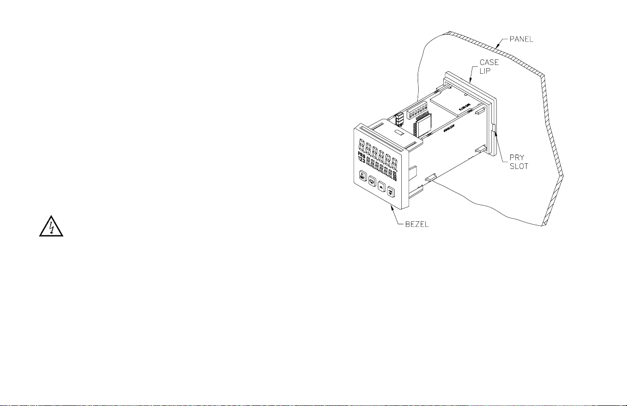
The unit assembly, shown in Figure 4, must be removed from the case to
change DIP switch settings or to replace the relay output board. To remove the
unit assembly, insert a flat blade screwdriver into the pry slot on either side of
the unit. Twist the screwdriver handle until the unit is ejected enough to allow
removal.
Caution: The unit assembly contains electronic circuits that can be damaged by
static electricity. Before removing the assembly, discharge static charge on
your body by touching an earth ground point. It is also important that the unit
assembly be handled only by the bezel. Additionally, if it is necessary to
handle a circuit board, be certain that hands are free from dirt, oil, etc., to
avoid circuit contamination that may lead to malfunction. If it becomes
necessary to ship the unit for repairs, place the unit in its case before
shipping it.
Installing Unit Assembly
To install the unit assembly, insert the assembly into the case until the bezel
is fully seated against the lip of the case. Properly installing the unit assembly
is necessary for watertight front panel sealing.
-4-
Figure 4, Unit Assembly
Page 11
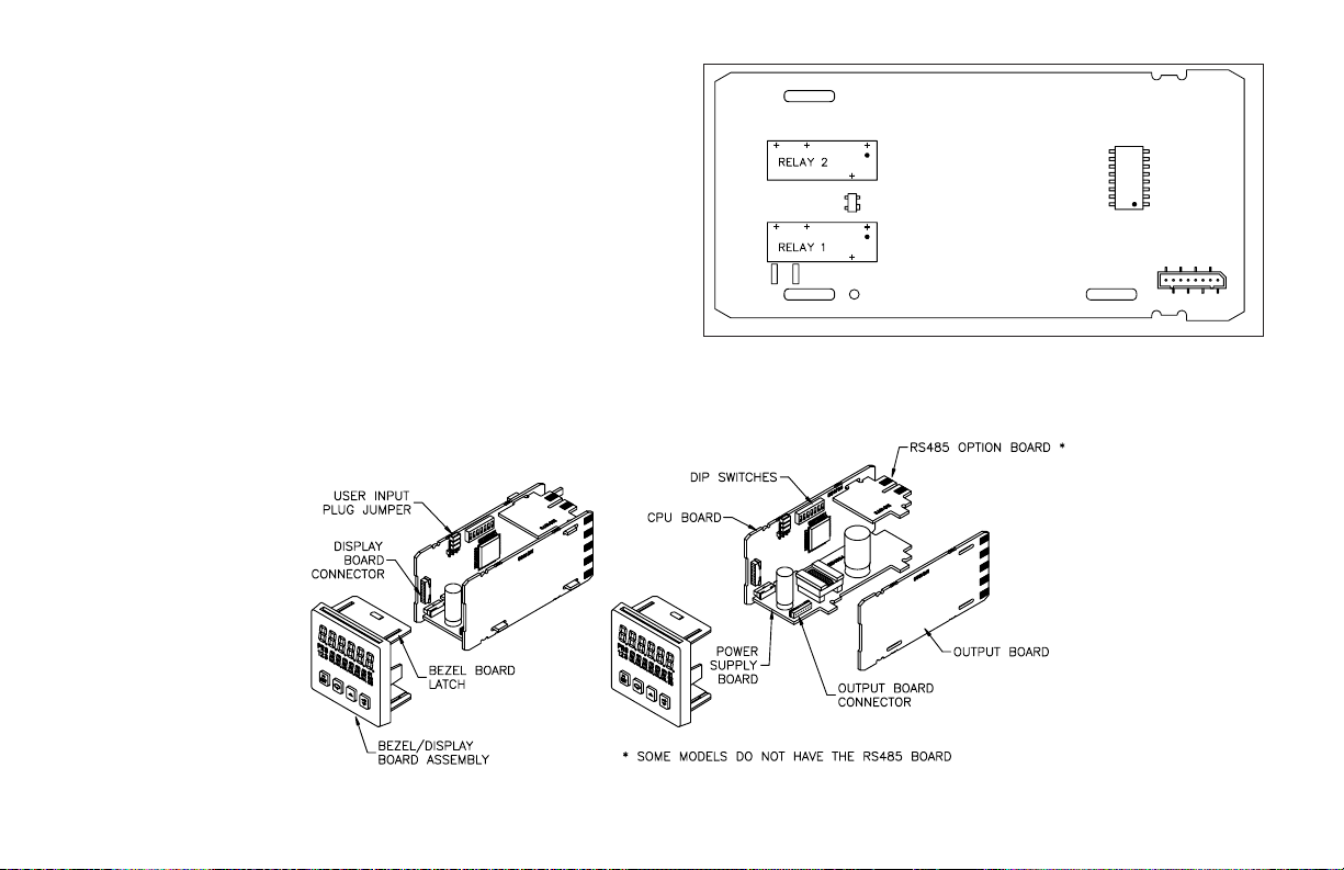
Output Board
The C48C is supplied with an output board installed. The output board is
preconfigured for the type of output needed, based upon the Model ordered. See
Ordering Information, page 48, for available models. All relay output boards are
field replaceable.
Replacing Relay Output Board
1. Remove the unit assembly. (See Removing Unit Assembly, page 4).
2. Lift up on the top bezel board latch while gently pulling out on the
bezel/display board assembly. Do NOT remove the display board from the
bezel.
3. Remove the output board by pulling it away from the other boards. Replace
the output board by aligning the board to board connectors. Be certain
connectors are fully mated.
4. Connect the bezel/display board assembly by guiding the board ends into the
bezel latches. Slide the assembly on evenly until the display board connector
is completely engaged and bezel latches are fully seated onto the boards.
Note: When replacing the relay output board, be certain to install a new
output board of the same type.
-5-
Figure 6, Relay Output Board Replacement
Figure 5, Relay Output Board
Page 12

EMC INSTALLATION GUIDELINES
Although this unit is designed with a high degree of immunity to ElectroMagnetic Interference (EMI), proper installation and wiring methods must be
followed to ensure compatibility in each application. The type of electrical
noise, source or coupling method into the unit may be different for various
installations. The unit becomes more immune to EMI with fewer I/O
connections. Cable length, routing and shield termination are very important
and can mean the difference between a successful installation or a troublesome
installation. Listed below are some EMC guidelines for successful installation
in an industrial environment.
1. The unit should be mounted in a metal enclosure, that is properly connected
to protective earth.
2. Use shielded (screened) cables for all Signal and Control inputs. The shield
(screen) pigtail connection should be made as short as possible. The
connection point for the shield depends somewhat upon the application.
Listed below are the recommended methods of connecting the shield, in order
of their effectiveness.
a. Connect the shield only at the panel where the unit is mounted to earth
ground (protective earth).
b. Connect the shield to earth ground at both ends of the cable, usually when
the noise source frequency is above 1 MHz.
c. Connect the shield to common of the unit and leave the other end of the
shield unconnected and insulated from earth ground.
3. Never run Signal or Control cables in the same conduit or raceway with AC
power lines, conductors feeding motors, solenoids, SCR controls, and
heaters, etc. The cables should be run in metal conduit that is properly
grounded. This is especially useful in applications where cable runs are long
and portable two-way radios are used in close proximity or if the installation
is near a commercial radio transmitter.
4. Signal or Control cables within an enclosure should be routed as far away as
possible from contactors, control relays, transformers, and other noisy
components.
5. In extremely high EMI environments, the use of external EMI suppression
devices, such as ferrite suppression cores, is effective. Install them on Signal
and Control cables as close to the unit as possible. Loop the cable through the
core several times or use multiple cores on each cable for additional
protection. Install line filters on the power input cable to the unit to suppress
power line interference. Install them near the power entry point of the
enclosure. The following EMI suppression devices (or equivalent) are
recommended:
Ferrite Suppression Cores for signal and control cables:
Fair-Rite # 0443167251 (RLC #FCOR0000)
TDK # ZCAT3035-1330A
Steward #28B2029-0A0
Line Filters for input power cables:
Schaffner # FN610-1/07 (RLC #LFIL0000)
Schaffner # FN670-1.8/07
Corcom #1VR3
Note: Reference manufacturer’s instructions when installing a line filter.
6. Long cable runs are more susceptible to EMI pickup than short cable runs.
Therefore, keep cable runs as short as possible.
7. Switching of inductive loads produces high EMI. Use of snubbers across
inductive loads suppresses EMI.
Snubbers:
RLC #SNUB0000
Wiring Connections
All conductors should meet voltage and current ratings for each terminal.
Also cabling should conform to appropriate standards of good installation, local
codes and regulations. It is recommended that power supplied to the unit (AC
or DC) be protected by a fuse or circuit breaker.
After the unit has been mechanically mounted, it is ready to be wired. All
wiring connections are made to rear screw terminals. When wiring the unit, use
the numbers on the label and those embossed on the back of the case, to identify
the position number with the proper function. See page 46 for terminal
descriptions. Strip the wire, leaving approximately 1/4” (6 mm) bare wire
exposed (stranded wires should be tinned with solder). Insert the wire under the
clamping washer and tighten the screw until the wire is clamped tightly.
Caution: Unused terminals are NOT to be used as tie points. Damage to the
counter may result if these terminals are used.
-6-
Page 13

POWER WIRING
AC Versions (C48CXX0X)
AC Power Wiring
Primary AC power is connected to terminals 11 and 12, labeled AC. To
reduce the chance of noise spikes entering the AC line and affecting the counter,
an AC feed separate from that of the load should be used to power the counter.
Be certain that the AC power to the counter is relatively “clean” and within the
specified range. Connecting power from heavily loaded circuits or circuits that
also power loads that cycle on and off, (contacts, relays, motors, etc.) should be
avoided.
DC Power Wiring (Non PNP Output models)
The DC power is connected to terminals 9 & 10, marked COMM. and DC
OUT/IN. The DC power source must be capable of supplying the unit’s rated
current (150 mA max.) and be within the specified 11 to 14 VDC range. The
C48C has non-volatile memory that stores information on power down, thereby
eliminating the need for battery back-up.
Note: AC Versions with PNP outputs cannot be powered from DC.
DC Versions (C48CXX1X)
DC power (18 to 36 VDC) or low voltage AC power (24 VAC) is connected
to terminals 11 and 12, labeled DC+ (AC) and DC- (AC) respectively.
Output Power
For DC/ Low Voltage AC units that do not have PNP current sourcing
outputs, Terminal 10, DC OUT (V
SRC
IN), provides a DC output for sensor
power (+12 VDC +/-15%). The maximum sensor current is 100 mA.
For units with PNP current sourcing outputs, this terminal serves a dual
purpose depending on the application’s PNP output voltage level and current
requirements.
1. The terminal may be used as a +12 VDC output for sensor power. In this
case, the PNP output voltage level will be +12 VDC (±15%). A maximum
of 100 mA is available for the combination of sensor current and PNP
output sourcing current.
2. If a higher PNP output voltage level or additional output sourcing current
is desired, an external DC supply may be connected between the “DC
OUT (V
SRC
IN)” and “COMM.” terminals. This supply will determine the
PNP output voltage level, and must be in the range of +13 to +30 VDC.
An external DC supply can also provide the additional output sourcing
current required in applications where two or more PNP outputs are
“ON” simultaneously. However, the maximum current rating of 100
mA per individual output must not be exceeded, regardless of external
supply capacity.
-7-
CAUTION: Observe proper polarity when connecting DC
voltages. Damage to the unit will occur if polarity is
reversed.
Page 14
Serial Communications Wiring
It is recommended that shielded (screened) cable be used for serial
communications. This unit meets the EMC specifications using Alpha #2404
cable or equivalent. There are higher grades of shielded cable, such as four
conductor twisted pair, that offer an even higher degree of noise immunity.
Refer to RS-485 Serial Communications, page 30, for wiring and operational
procedures.
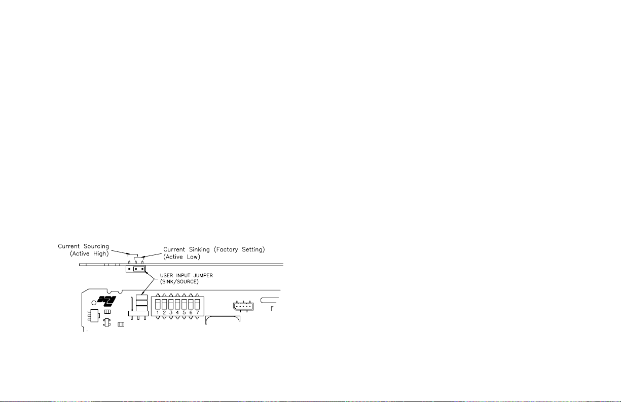
User Inputs
The external user inputs are programmable inputs that can be configured as
current sinking (active low) or current sourcing (active high) inputs via a single
plug jumper. Programmable external user inputs are digital inputs. The use of
shielded cable is recommended. Follow the EMC Installation Guidelines for
shield connection. The active logic state of ALL user inputs is dictated by the
position of the User Input plug jumper. The plug jumper is located on the CPU
board to the left of the DIP switches (See Figure 7, User Input Jumper
Location). Input/User B can be programmed to be a user input when only
unidirectional counting is required (See CNT IN parameter, page 17). When
programmed as a User Input, Input B’s active logic level is also controlled by
the User SNK/SRC plug jumper.
OUTPUT WIRING
Relay Connections
To prolong contact life and suppress electrical noise interference due to the
switching of inductive loads, it is good installation practice to install a snubber
across the contactor. Follow the manufacturer’s instructions for installation.
Note: Snubber leakage current can cause some electro-mechanical devices to be
held ON.
Input A and Input/User B
Input A and Input B have identical circuitry and share the same “COMM.”
terminal. Each input has separate DIP switches that configure the circuitry to
accept various types of sensor outputs.
The input schematic shows the details of the input circuitry. Each input has
three DIP switches whose functions are listed below.
To access the DIP switches, the unit assembly must be removed from the
case. See Removing The Unit Assembly, page 4, for instructions.
INPUT A
SW1 - SNK: Provides a 7.8 KΩ internal pull-up resistor for sensors with
current sinking outputs.
SRC: Provides a 3.9KΩ internal pull-down resistor for sensors with
current sourcing outputs.
SW2 - HI FRQ: Removes damping capacitor and allows operation up to the
maximum input frequency.
LO FRQ: Connects damping capacitor for switch contact debounce.
Limits count speed to 50 Hz maximum and count pulse ON or OFF
times to 10 msec. minimum.
Note:The HI/LO FRQ selection switch must be set on “LO FRQ” when switch
contacts are used to generate count input signals. The “LO FRQ” mode also
provides very high immunity against electrical noise pickup. It is
recommended that this mode also be used, whenever possible, with electronic
sensor outputs. The “LO FRQ” mode can be used with any type of sensor
output, provided count pulse widths never decrease below 10 msec, and the
count rate does not exceed 50 Hz.
-8-
Figure 7, User Input Jumper Location
Page 15
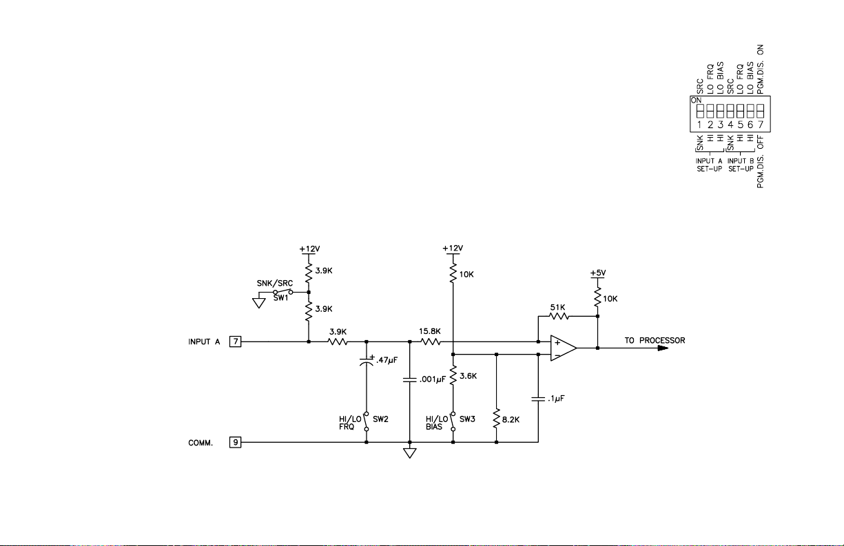
SW3 - HI BIAS: Sets input trigger levels at mid-range, to accept outputs from
2-wire proximity sensors, resistive photo-cells, and logic pulses
with full 0 to +12V swings.
Input trigger levels: VIL= 5.5 V max; VIH= 7.5 V min.
LO BIAS: Sets input trigger levels to low range, to accept logic pulses
with 0 to +5 V swings.
Input trigger levels: VIL= 1.5 V max; VIH= 3.75 V min.
Note: VILand VIHlevels given are typical values ±10%, when the counter
voltage at the DC OUT/IN terminal, is +12 VDC. These typical values will
vary in proportion to the variations in DC OUT/IN terminal voltage, caused
by line voltage and load changes.
INPUT B
SW4 - Same as SW1
SW5 - Same as SW2
SW6 - Same as SW3
SW7 - PGM.DIS.: See Front Panel Accessible
Functions With Program Disable,
page 14, for details.
-9-
Figure 9, Input Circuit Schematic
Figure 8, DIP Switches
Note: Input B uses
DIP switches SW4,
SW5 and SW6.
Page 16
-10-
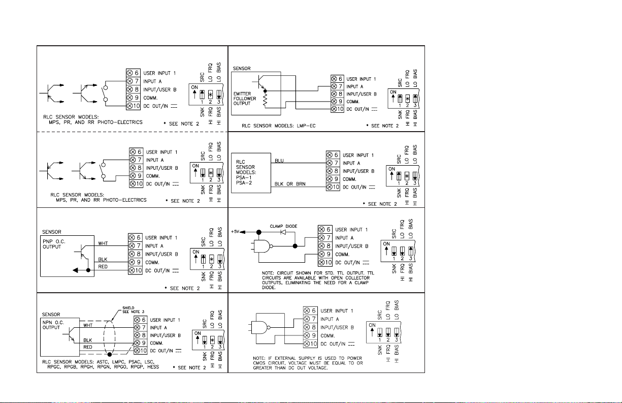
Various Sensor Output Connections
SENSORS WITH CURRENT SOURCE OUTPUT (PNP O.C.)
(COUNT ON TURN-OFF)
2 WIRE PROXIMITY SENSORS - CURRENT SOURCE CONNECTED
(COUNT ON CURRENT FALL)
OLDER STYLE SENSORS WITH E-F OUTPUT - CURRENT
SOURCE CONNECTED (COUNT ON FALLING EDGE)
SENSORS WITH CURRENT SINK OUTPUT (NPN O.C.)
(COUNT ON TURN-ON)
CURRENT SINK CONNECTED (COUNT ON CLOSING)
INTERFACING WITH CMOS CIRCUITRY (B TYPE)
NOTES:
1. SENSOR VOLTAGE AND CURRENT
The DC OUT/IN terminal can supply +12
VDC @ 100 mA max. within a ±15%
range, due to line and internal load
variations. Most RLC sensors will
accommodate this range.
2. HI/LO FRQ SELECTION
The HI/LO FRQ selection switch must be
set on “LO FRQ” when switch contacts
are used to generate count input signals.
The “LO FRQ” mode also provides very
high immunity against electrical noise
pickup. It is recommended that this mode
also be used, whenever possible, with
electronic sensor outputs. The “LO FRQ”
mode can be used with any type of sensor
output, provided count pulse widths never
decrease below 10 msec, and the count
rate does not exceed 50 Hz.
3. When shielded cable is used, connect the
shield to “COMM.” at the counter and
leave it disconnected at the sensor end.
4. Inputs A and B can accept source pulses
from other circuits up to +30 V in
amplitude. For voltages above +30 V, a
limiting resistor and zener diode should
be used to limit the voltage at the input
terminal.
INTERFACING WITH TTL
COUNT SWITCH OR ISOLATED TRANSISTOR OUTPUTS
CURRENT SOURCE CONNECTED (COUNT ON OPENING)
Page 17
The front panel bezel material is flame and
scratch resistant, textured plastic with clear
viewing window that meets NEMA 4X/IP65
requirements, when properly installed.
Continuous exposure to direct sunlight might
accelerate the aging process of the plastic
material used in the bezel. The bezel should be
cleaned only with a soft cloth and neutral soap
product. Do NOT use solvents.
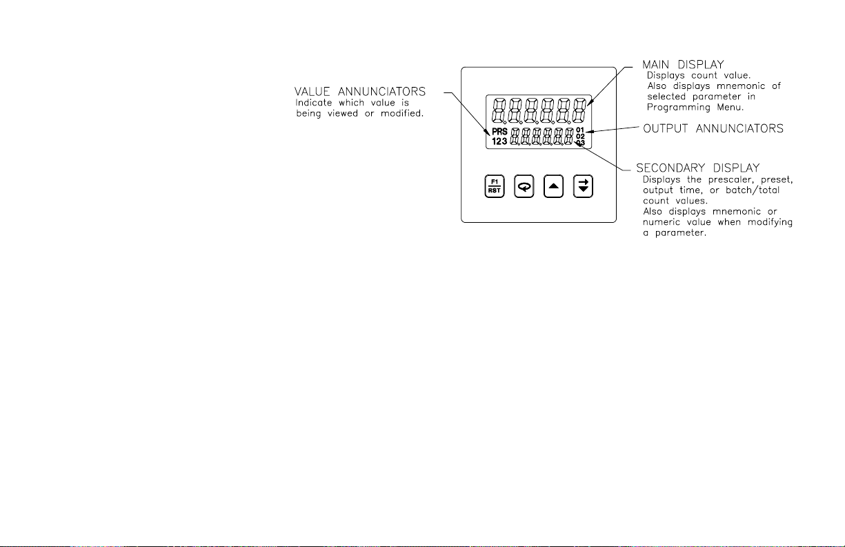
The display is a dual line, 6 digit LCD. On
units with backlighting, the upper Main
Display is red and the lower Secondary
Display is green.
There are up to seven annunciators available
in the lower display that illuminate to inform the operator of the counter and
output status. See Figure 10, Front Panel, for a description of the annunciators.
Four front panel keys are used to access different modes and parameters. The
following is a description of each key.
Do not use tools of any kind (screwdrivers, pens, pencils, etc.) to operate the
keypad of this unit.
Keypad Functions
D- This key is a user programmable key. When the key is pressed, the unit
performs the appropriate function as programmed. The RST printing on
this key is used as a quick reference for the operator if the function key is
selected for a reset function.
A - This key is used to access programming, enter changes to data values,
and scroll through the available parameters in any mode.
B - This key selects the next available mode option during programming.
When programming a numerical value in digit entry mode, this key is used
to increment the selected digit position. In auto scrolling entry mode, it
increments the value. When in the operating mode, this key is pressed to
allow changing of the data value viewed in the secondary display.
C - When programming a numerical value in digit entry mode, this key
accesses the value and selects the digit to the right. In auto scrolling entry
mode, it decrements the value. When in the operating mode, this key is
pressed to allow changing of the data value viewed in the secondary
display.
-11-
Figure 10 , Front Panel
FRONT PANEL DESCRIPTION
Page 18

BASIC OPERATION
Single and Dual Preset Units
The C48CS and C48CD have one counter that keeps track of the input pulse
count. On each counter edge, the prescaler value is added to or subtracted from
the count value. This results in the desired reading value for the count display.
The counter has two reset action modes; Reset to Zero ( up-count modes) and
Reset to Preset (down-count modes). A reset can be a manual reset, using a
programmable user input, or it can be one of the programmable automatic reset
modes.
The counter displays the scaled number of pulses that have been entered.
When the count equals either preset 1 or 2, depending on the model, the
appropriate output activates. The count can be programmed to automatically
reset if desired.
3 Preset Batch Unit
The C48CB contains two counters that keep track of the Process Count, and
the Batch or Total Count. On each count edge, the prescaler value is added to or
subtracted from the count input value. This results in the desired reading value
for the process or total count displays. The batch count registers one count each
time the process is completed.
The process counter has two reset action modes; Reset to Zero (up-count
modes) and Reset to Preset (down-count modes). A reset can be a manual reset,
using a programmable user input, or it can be one of the programmable
automatic reset modes.
The batch counter displays the number of process cycles that have been
completed.
The total count is the total number of counts that have been received since the
total was last reset. It can be used to keep a running total of process units on a
desired per shift, per day, per week, etc. basis.
Normal Operating Mode
In the normal operating mode, the count or batch/total value is shown on the
main display. By successively pressing the A key, the accessible presets,
prescaler, output time values, or batch/total count can be viewed in the
secondary display.
With the exception of the batch/total count, each of the values can be
independently programmed to be viewable only, viewable and changeable, or
locked (not viewable) in the normal operating mode. On the batch models, if all
values are locked, only the batch/total count value is viewable in the secondary
display. On single or dual preset models, the display will be blank. Only from
the normal operating mode can access be gained to the Programming Menu or
Protected Value Menu.
Modifying A Secondary Display Parameter
From the Front Panel
Secondary display parameters can be modified from the normal operating
mode if the Operator Access privileges allow it.
To modify a parameter, it must be viewed in the secondary display. When the
parameter to be modified is viewed, press the B or C key. Leading zeros
appear and the least significant digit blinks. The value can now be modified as
described in Programming Numeric Data Values, page 15.
-12-
Page 19

Protected Value Menu
The Protected Value Menu allows access to selected presets,
prescaler, and output time values without having them viewable
or changeable from the main display. To enter the protected
menu, the A key is pressed and held, and a code value is
entered. The Protected Value Menu and the Programming
Menu are not available at the same time. See Front Panel
Accessible Functions With Program Disable, page 14, for
available options.
Access value parameters that are programmed for “P” or “n”
are accessible in the Protected Value Menu. Parameters
selected as “n” (no) are viewable from the main display, but can
only be changed in the protected menu. Parameters selected as
“P” (protected) are not viewable from the main display, but can
be viewed and changed in the protected menu.
-13-
Figure 11, Protected Value Menu
Page 20

There are several ways to limit the programming of parameters from the front
panel keypad. The Accessible Value parameters are used with the Program
Disable DIP switch and an external programmable User Input selected for
Pro.dis to limit programming. To enter the programming mode, a code number
may need to be entered, depending on the Program Disable Setting. Front Panel
Function Key F1 cannot be selected for program disable. The following table
describes the possible program disabling functions.
-14-
Front Panel Accessible Functions With Program Disable
PGM.DIS.
SWITCH
USER INPUT TERMINAL
PROGRAM CODE
NUMBER
PROTECTED VALUE
MENU
OPERATOR ACCESS AT
MAIN DISPLAY
PROGRAM
DISABLE LEVEL
PROGRAMMING
ENABLED
OFF
INACTIVE or Not
Programmed for Pro.dis
ALL No
All displayed values
changeable
NoneYes
OFF ACTIVE 0 No
Per Access Privileges
programmed
Level 1No
OFF ACTIVE 1 to 99
Yes
W/code
Per Access Privileges
programmed
Level 1No
OFF ACTIVE 100 to 199 No
Per Access Privileges
programmed
Level 1
Yes
W/code
ON
INACTIVE or Not
Programmed for Pro.dis
0 No
Per Access Privileges
programmed
Level 1No
ON
INACTIVE or Not
Programmed for Pro.dis
1 to 99
Yes
W/code
Per Access Privileges
programmed
Level 1No
ON
INACTIVE or Not
Programmed for Pro.dis
100 to 199 No
Per Access Privileges
programmed
Level 1
Yes
W/code
ON ACTIVE ALL No Viewable only Level 2No
Page 21

Programming of the C48 Counter is done through the front panel keypad.
English language prompts, flashing parameter values, and the front panel
keypad aid the operator during programming.
Although the unit has been programmed at the factory, the parameters
generally have to be changed to suit the desired application. In order to access
the Programming Menu, the Program Disable DIP switch and/or any User Input
programmed for Pro.dIS may need to be turned off or deactivated. When
shipped from the factory, all programming is enabled. See Front Panel
Accessible Functions With Program Disable, page 14, for program disabling
options. With programming enabled, to enter the programming menu, the A
key is pressed and held for two seconds. Once in the programming menu, the
A key is used to sequence through the list of programming parameters. To loop
backwards one item in the Programming Menu, press and hold the A key, then
quickly press and hold the C key while releasing the A key. Repeatedly
pressing the A key with the C key held will continue the backwards
sequencing.
Programming Option Values
The operator can scroll through the available options for a selected parameter
by pressing the B or C keys to enter parameter change mode, and then
pressing the B key repeatedly until the desired option is viewed. The option is
entered by pressing the A key, which returns the operator to the Programming
Menu.
Programming Numeric Data Values
The presets, prescaler, and output time values may be accessible when the
unit is in the normal operating mode (not programming mode), providing that
the Program Disable input is not activated. Pressing the A key will sequence
the secondary display through the available presets, prescaler, and output time
values.
To change a numeric data value it must be visible on the secondary display.
Pressing the B or C key will allow changing of the value. The two methods
for changing numeric data values are “digit entry” and “auto scrolling”.
Digit Entry
If the data entry method has been set to “digit entry”, the least significant
digit will blink. Pressing the C key multiple times will select other digits.
Pressing the B key will increment the selected digit. The data value will be
entered when the A key is pushed, or the old value will be retained if no key
activity is detected for 10 seconds.
Short-Cut - Decrementing Value
To decrement a digit value, press and hold the B key and then press the C
key. This will decrement the selected digit to zero if held.
Auto Scrolling
If the data entry method is set to “auto scrolling”, the data value can be
progressively changed by pressing and holding the B or C keys. If one of the
keys is pushed and held, the value will scroll automatically. After 5 counts, the
unit enters fast scroll mode. If a key remains pushed, a digit shift occurs every
one hundred counts until the maximum value or zero is reached. When the digit
shift occurs, the previously scrolling digit goes to zero. When scrolling at the
higher order digit locations, you can switch directions by quickly pressing the
other key (B or C) within a second following the release of previous direction
key.
Short-Cut - Quick Digit Shift
To quickly select higher order digits while incrementing or decrementing
numeric values (with B or C held), press and hold the A key. This sequences
the selected digit from the least to the most significant digit. As each digit is
passed, it changes to zero. When the desired digit is reached, release the A key
to increment or decrement from the new digit location.
Saving Program
All parameter values changed in programming mode are saved when exiting.
To exit programming mode, press and hold the A key for two seconds. The
display will momentarily display Pro9 SAVE while the parameter values are
saved in non-volatile memory. The unit then returns to the indication display
that was last viewed.
-15-
PROGRAMMING GENERAL DESCRIPTION
Page 22

PScALr
PRS
1.00000
Ac PSc
-L
The operating modes of the C48 Counter are programmed using the front
panel keypad. Accessibility to the Programming Menu depends on the Program
Disable Function setting (See Front Panel Accessible Functions With Program
Disable, page 14, for available settings).
Note: Before attempting to program the C48C, read the section Programming
General Description, page 15, for detailed information on using the front
panel keypad to navigate through the Programming Menu.
Programming Menu
Numeric Value entry method
Configures push button response for entering numeric
data values such as Presets, Prescaler, and Output Times.
-16-
Access Prescaler Value
This parameter configures the type of access given to the
Prescaler Value when in normal operating mode with
Programming disabled. For more information on Program
Disable, see page 14.
Prescaler (0.00001 - 9.99999*)
The Prescaler is used to convert a pulse input signal to the
desired units of indication. For each pulse input, the
Prescaler value is added to or subtracted from the internal
count value. A prescaler of 1.00000, provides unity scaling,
i.e., for every pulse input, the display changes by 1. The
prescaler value selected will affect the maximum count rate
(See Appendix B - Specifications, page 39).
It is important to note that the precision of a counter
application cannot be improved by using a prescaler greater
than 1.
*Limited to 1.00000 or less on Prescaler Output Model or
when Counter 2 is assigned to total on the Batch Counter.
USER INTERFACE/PROGRAMMING MODES
MODE DESCRIPTION
diGit
The digit entry method allows the selecting and
incrementing of each numeric digit on an
individual digit-by-digit basis.
AutoSc
MODE DESCRIPTION
-L
-y
Yes; Prescaler value is viewable and changeable
at main display when at 1st level program disable.
Value is not shown in Protected Value Menu.
-n
-P
Protected Value; Prescaler value is viewable and
changeable in Protected Value Menu only. It is not
viewable at Main Display.
EntrY
AutoSc
Locked; Prescaler is not viewable at main display
or in Protected Value Menu. The Prescaler can
only be viewed or changed in the Programming
Menu.
The auto scrolling method allows pressing and
holding the “up” or “down” keys to progressively
change all digits of the data value, similar to
incrementing or decrementing a counter.
No; Prescaler value is viewable only and not
changeable from main display when Programming
is Disabled. Value is viewable and changeable in
Protected Value Menu.
Page 23

Decimal Point Position
Programmable for display of 0 to 5 digits right of decimal
point.
Count Input Mode
This parameter controls the Count / Control function of
Inputs A and B. It also allows Input B to be used as a User
Input when only uni-directional counting is required.
-17-
Count Modes
Input A signal is used for the count input. Input B is used in combination
with Input A for Count Direction Control, Quadrature counting, Anticoincidence Add/Subtract, or Anti-coincidence Add/Add counting applications.
C1-USR - The unit counts one count on every negative edge of the input signal
at Input A. In this mode, Input B acts as a user input and has no effect on the
count function.
C2-USR - The unit counts one count on every negative edge of the input signal
and one count on every positive edge of the input signal at Input A. In this
mode, the input signal is effectively doubled. Input B acts as a user input and
has no effect on the count function.
C1-UD - The unit counts one count on every negative edge of the input signal
at Input A. The direction of the count is determined by the logic state of Input
B. A high level at Input B causes the unit to count in a positive direction. A
low level causes the unit to count in a negative direction.
C2-UD - The unit counts one count on every negative edge of the input signal
and one count on every positive edge of the input signal at Input A. In this
mode, the input signal is effectively doubled. The direction of the count is
determined by the logic state of Input B. A high level at Input B causes the
unit to count in a positive direction. A low level causes the unit to count in a
negative direction.
AD-SUB - This mode effectively separates count pulses that may
simultaneously appear at the two inputs. The C48C processes the count
pulses into a string of time separated pulses, so the internal counter does not
miss any count pulses. Input A serves as the add input (count increments) and
Input B serves as the subtract input (count decrements).
AD-AD - This mode effectively sums count pulses that may simultaneously
appear at the two inputs. The C48C processes the count pulses into a string
of time-separated pulses so the internal counter does not miss any count
pulses. Input A serves as an add input (count increments) and Input B serves
as an additional add input (count increments).
MODE DESCRIPTION
------
No decimal Point
Decimal point for 10ths
----.--
Decimal point for 100ths
---.---
Decimal point for 1000ths
--.----
Decimal point for 10,000ths
-.-----
Decimal point for 100,000ths
-----.-
MODE Input A Input B
C1-USr*
Count X1;
Count on falling edge
User Input B (See
UsrInb parameter)
C2-USr
Count X2;
Counts on both edges
C1-Ud*
Count X1;
Counts on falling edge
C2-Ud
Count X2;
Counts on both edges
Up/Down control;
Input B high = Up
Input B Low = Down
Ad-Sub
Add count;
Counts on falling edge
Subtract count;
Counts on falling edge
Ad-Ad
Add count;
Counts on falling edge
Add count;
Counts on falling edge
qUAd 1
Quadrature X1 Input Quadrature X1 Input
qUAd 2
Quadrature X2 Input Quadrature X2 Input
qUAd 4
Quadrature X4 Input Quadrature X4 Input
Up/Down control;
Input B high = Up
Input B Low = Down
User Input B (See
UsrInb parameter)
*- These are the
only count
input modes
available on
the Prescaler
Output model.
Cnt In
C1-Ud
dEc Pt
------
Page 24

QUAD 1 - Quadrature counting modes are primarily used in positioning and
anti-jitter applications. This mode works due to the manner in which the two
incoming pulses are positioned relative to each other. The pulse signal on
Input B is shifted 90° away from the pulse signal at Input A. These two
signals are processed by the C48C as follows:
Input A serves as the count input, while Input B serves as the quadrature
input. For quadrature with single edge counting, the counter counts in a
positive direction when Input A is a negative going edge and Input B is at a
low level. The counter counts in a negative direction when Input A is a
positive going edge and Input B is at a low level. All transitions on Input A
are ignored when Input B is at a high level. These logic rules provide the
basis for anti-jitter operation which prevents false counts from occurring due
to back-lash, vibration, chatter, etc.
QUAD 2 - When two edge counting is used, the quadrature mode works the
same as with single edge counting when Input B is low. But, when Input B
is a high level, counts at Input A are no longer ignored. Instead, the logic
rules for Input A are complemented, allowing both edges of Input A to be
counted. This doubles the effective resolution of the encoded input.
QUAD 4 - This takes the quadrature mode, with two edge counting, one step
further. In quadrature times 4, both Input A and Input B serve as the count or
quadrature input, depending on their state. In one instance, Input A serves as
the count input and Input B serves as the quadrature input. In another
instance, Input A is the quadrature input and Input B is the count input. This
enables each edge, positive and negative going , of both inputs, A and B, to
be counted. This results in a resolution four times greater than in the basic
quadrature X1 mode.
Counter (1) Operating Mode
The charts on the following pages show operating modes
for Single Preset and the Dual Preset / Batch Counter
Models. In the descriptions below the “Main Preset or
Output” refers to “Preset or Output 1” on the Single Preset
Model. On the Dual Preset or Batch Models it refers to
“Preset or Output 2”.
-18-
OPEr
11
OPEr 1
11
Single or Dual
Preset Model
Batch Model
Reset Type:
Auto - unit automatically resets when count triggers
main preset’s output or at its timed output end, as
programmed.
Manual - unit does not reset when count triggers main
presets output or at its timed output end. The counter
can be manually reset by a User Input or by a Serial
Communications command.
Reset to:
Zero - When reset (manually or automatically) counter goes to zero. The
Main Preset Output is triggered when count value reaches main Preset
Value
Preset - When reset (manually or automatically), the main Preset value is
loaded into the counter. The main Preset Output is triggered when count
reaches zero.
At Timed Output End:
When this mode is selected, Auto Reset occurs when the main preset’s
Output time elapses and the main output deactivates. If not selected, Auto
reset occurs when the main output is triggered.
Output 1: (Main Output for Single Preset Model)
Latched - When Output 1 activates, it stays activated or latched until it is
manually reset.
Timed - When Output 1 is activated it stays activated for the time specified
by the Output 1 Time Value. Output 1 deactivates after the Output 1 time
elapses.
O1 Off at O2: (Dual Preset / Batch Model only)
Output 1 activates at Preset 1. It deactivates when Output 2 is activated. Does
not apply when activating Output 2 using Serial Communications command.
Output 2: (Dual Preset / Batch Model only; Main Output)
Operates similarly to Output 1 Latched and Timed modes.
Page 25

SINGLE PRESET OPERATING MODES
Use either of the two charts below for more information on specific operating
modes.
-19-
MODE# RESET TYPE
Manual
Auto
RESET
To Zero
To Preset
at Timed
Output
End
OUTPUT 1
Latched
Timed
√√√
1
2
√ √ √
3
√ √ √
√√√
4
√√√
5
√√√
6
√√√√
7
√√√√
8
SINGLE PRESET OPERATING MODES
Auto Reset to Preset at Timed Output End-8
Auto Reset to Zero at Timed Output End-7
Auto Reset to Preset, Timed Output-6
Auto Reset to Zero, Timed Output-5
Manual Reset to Preset, Timed Output
-4
Manual Reset to Preset, Latched Output-3
Manual Reset to Zero, Timed Output-2
Manual Reset to Zero, Latched Output-1
1 - Manual Reset to Zero, Latched Outputs
2 - Manual Reset to Zero, 01 Timed, 02 Latched
3 - Manual Reset to Zero, 01 and 02 Timed
4 - Manual Reset to Zero, 01 off at 02, 02 Latched
5 - Manual Reset to Zero, 01 off at 02, 02 Timed
6 - Manual Reset to Preset 2, Latched Outputs
7 - Manual Reset to Preset 2, 01 Timed, 02 Latched
8 - Manual Reset to Preset 2, 01 and 02 Timed
DUAL PRESET AND BATCH COUNTER 1 OPERATING MODES
9 - Manual Reset to Preset 2, 01 off at 02, 02 Latched
10 - Manual Reset to Preset 2, 01 off at 02, 02 Timed
11 - Auto Reset to Zero, 01 and 02 Timed
12 - Auto Reset to Zero, 01 off at 02, 02 Timed
13 - Auto Reset to Preset 2, 01 and 02 Timed
14 - Auto Reset to Preset 2, 01 off at 02, 02 Timed
15 - Auto Reset to Zero at 02 End, 01 and 02 Timed
16 - Auto Reset to Zero at 02 End, 01 off at 02, 02 Timed
17 - Auto Reset to Preset 2 at 02 End, 01 and 02 Timed
18 -
DUAL PRESET/ BATCH COUNTER 1 OPERATING MODES
Use either of the two charts below for more information on specific
operating modes.
Auto Reset to Preset 2 at 02 End, 01 off at 02, 02 Timed
Page 26

Counter 2 Assignment (Batch Model only)
This parameter configures Counter 2 to function as a
Batch or Total Counter.
Counter 2 Count Direction when configured as a Totalizer
When Counter 2 is assigned to Total, the Prescaler value is limited to
1.00000 or less. For Prescaler values less than one, that are not evenly
divisible into the Preset 2 value, the Total count incurs an accumulating
error of up to 1 count for every auto reset cycle of Counter 1. In effect,
it does not accumulate the “total” amount of material used, it
accumulates the “total” number of counts registered in Counter 1.
DUAL PRESET/ BATCH COUNTER 1 OPERATING MODES
-20-
Manual
RESET TYPE
Auto
RESET
To Zero
To Preset
2
at Timed
02 End
OUTPUT 1
Latched
Timed
O1 Off at
O2
OUTPUT 2
Latched
Timed
√√√√
1
2
√ √ √ √
√√√√
3
4
√ √ √ √
√√√√
5
6
√ √ √ √
√√√√
7
8
√ √ √ √
√√√√
9
10
√ √ √ √
√√√√
11
12
√ √ √ √
√√√√
13
14
√ √ √ √
√√√√√
15
16
√ √ √ √ √
√√√√√
17
18
√ √ √ √ √
MODE#
Reversed
Count
Direction
UpDnUpDn
Normal Count
Direction
DnUpDnUp
Count Reset
Modes
Reset to
P3
Reset to
0
Reset to
P2
Reset to
0
NOTES
RESULTANT COUNTER 2
COUNT DIRECTION FOR
C2 OPERATING MODE
COUNTER 1 COUNT
DIRECTION FOR C1
OPERATING MODE
Counter 2 operates as a totalizing counter. The totalizer counts
whenever Counter 1 increments or decrements. The count direction is
determined by; Counter 1 count direction, Counter 1 Operating “Reset
to” mode, and the Counter 2 Operating “Reset to” mode.
totAL
Counter 2 operates as a batch counter. A batch is counted when Output
2 of Counter 1 is triggered. The Count direction is determined by the
Counter 2 Operating Mode.
bAtch
DESCRIPTIONMODE
C2 ASn
bAtch
Page 27

Counter 2 Operating Mode (Batch Model only)
-21-
The chart below shows operating modes for Counter 2 of the Batch Counter
Model.
OPEr 2
1
RESET TYPE RESET OUTPUT 3
Auto
To
ZeroToPreset 3
Latched Timed
1
√ √ √
2
√ √ √
3
√ √ √
4
√ √ √
5
√ √ √
6
√ √ √ √
7
√ √ √
8
√ √ √ √
MODE
#
Manual
At Timed
03 End
COUNTER 2 OPERATING MODES (C48CB ONLY)
Auto Reset to Preset 3 at 03 Timed Output End-8
Auto Reset to Preset 3, 03 Timed-7
Auto Reset to Zero at 03 Timed Output End-6
Auto Reset to Zero, 03 Timed-5
Manual Reset to Preset 3, 03 Timed-4
Manual Reset to Preset 3, 03 Latched
-3
Manual Reset to Zero, 03 Timed-2
Manual Reset to Zero, 03 Latched-1
Reset Type:
Auto - unit automatically resets when count reaches
Output 3 or timed output 3 end.
Manual - Counter can only be manually reset by a User
Input or by Serial Communications command.
Reset to:
Zero - When reset (manually or automatically), counter 2 goes to zero.
Output 3 is triggered when counter 2 value reaches Preset 3 Value
Preset - When reset (manually or automatically), the Preset 3 Value is loaded
into Counter 2. Output 3 is triggered when Counter 2 reaches zero.
At Timed Output 3 End:
When this mode is selected, Auto Reset occurs when the Output 3 time
value elapses and Output 3 deactivates. If not selected, Auto reset occurs
when output 3 is triggered.
Output 3:
Latched - When Output 3 activates, it stays activated or latched until it is
manually reset.
Timed - When Output 3 is activated, it stays activated for the time specified
by the Output 3 Time Value. Output 3 deactivates after the Output 3 time
duration expires.
Page 28

Access Preset Values
This parameter configures the type of access given to
each Preset Value when in normal operating mode with
Programming disabled. The accessibility of each Preset can
be individually configured. For more information on
Program Disable, see Front Panel Accessible Functions
With Program Disable, page 14.
Programming Keys:
C - Selects Preset Value being configured as indicated by
the number on the left side of the bottom display line.
B - Changes mode selection for selected Preset.
-22-
Preset Values (0-999999)
The Preset Values control the activation of the respective
Outputs.
Preset 1 Value
The Preset 1 Value is used to control Output 1 and is
assigned to the main counter (Counter 1 on Batch Model)
Preset 2 Value (Dual Preset/Batch Models
only)
The Preset 2 Value is used to control Output 2 and is
assigned to the main counter (Counter 1 on Batch Model)
Preset 3 Value (Batch Model only
)
The Preset 3 values is used to control Output 3 and is
assigned to Counter 2.
Preset 1 Track Preset 2 (Dual Preset/Batch
Models only
)
This parameter configures whether or not the Preset 1
value tracks or follows the Preset 2 value.
Ac PrS
PRS
-Y
Ac PrS
PRS
-Y-Y
Ac PrS
PRS
-y-y-y
PrESEt
PRS
2
20
PrESEt
PRS
3
30
PltrAc
PRS
2
no
PrESEt
PRS
1
10
MODE DESCRIPTION
-L
Locked; Preset is not viewable at main display or
in Protected Value Menu. The Preset can only be
viewed or changed in the Programming Menu.
-y
-n
-P
Protected Value; Preset value is viewable and
changeable in Protected Value Menu only. It is not
viewable at Main Display.
Single Preset
Model
Dual Preset
Model
Batch Model
Dual Preset/Batch
Models
Dual Preset/Batch
Models
Batch Model
MODE DESCRIPTION
no
Preset 1 does not track Preset 2
YEs
Preset 1 tracks Preset 2 value. When Preset 2
value is changed the Preset 1 value will change
to maintain the same offset. Changing Preset 1
will modify the offset.
-OR-
-OR-
Yes; Preset value is viewable and changeable at
main display when at 1st level program disable.
Value is not shown in Protected Value Menu
Note: All three available secondary
display variations are shown above.
Subsequent displays pertaining to
outputs will show only the batch
version unless otherwise labeled.
No; Preset value is viewable only and not
changeable from main display when Programming
is Disabled. Value is viewable and changeable in
the Protected Value Menu.
Page 29

Access Output Time Values
This parameter configures the type of access given to
each Output Time Value when in normal operating mode
with Programming disabled (See Front Panel Accessible
Functions With Program Disable, page 14, for more details).
The accessibility of each Output Time Value can be
individually configured.
Programming Keys:
C - Selects Output Time Value being configured as
indicated by the number on the left of the bottom display.
B - Changes mode selection for selected Output Time
Value.
Output Resolution
This parameter configures the timed output resolution for
all available Timed Outputs. Use the 0.01SEC resolution if
all Output Time Values are below 99.99 seconds.
-23-
Output 1 Time Value
The Output 1 Time Value controls the Output 1 duration,
when Output 1 is set for timed mode of operation (OPEr or
OPEr 1 parameter). The Output time value range will be
0.01-99.99 Seconds or 0.1-999.9 seconds, depending on the
setting of the Output Resolution (OutrES) parameter.
Output 2 Time Value (Dual Preset/Batch
Models only)
The Output 2 Time Value controls the Output 2 duration,
when Output 2 is set for timed mode of operation (OPEr or
OPEr 1 parameter). The Output time value range will be
0.01-99.99 Seconds or 0.1-999.9 seconds, depending on the
setting of the Output Resolution (OutrES) parameter.
Output 3 Time Value (Batch Model only)
The Output 3 Time Value controls the Output 3 duration,
when Output 3 is set for timed mode of operation (OPEr 2
parameter). The Output time value range will be 0.01-99.99
Seconds or 0.1-999.9 seconds, depending on the setting of
the Output Resolution (OutrES) parameter.
Reverse Output Logic
This parameter individually configures whether or not the
Output Logic is reversed, for all Preset Outputs.
Ac Out
-L-L-L
OutrES
0.01SEC
rEVOut
-n-n-n
OutPut
1
t 0.10
OutPut
2
t 0.10
OutPut
3
t 0.10
MODE DESCRIPTION
-L
-y
-n
-P
Protected Value; Output Time Value is viewable and
changeable in Protected Value Menu only. It is not
viewable at Main Display.
MODE DESCRIPTION
0.01SEC
0.01 Second Output Resolution; Maximum
Output time: 99.99 Seconds
0.1 SEC
0.1 Second Output Resolution; Maximum
Output time: 999.9 Seconds
Dual Preset/
Batch Models
Batch Model
MODE DESCRIPTION
-n
-Y
Locked; Output Time Value is not viewable at main
display or in Protected Value Menu. The Output Time
Value can only be viewed or changed in the
Programming Menu.
Yes; Output Time Value is viewable and changeable
at main display when at 1st level program disable.
Value is not shown in Protected Value Menu.
No; Output Logic is not Reversed. Output / Relay
will turn ON at Preset Value or Zero (Reset to
Preset modes) and turn OFF when Reset or
Output Time expires.
Yes; Output Logic is Reversed. Output / Relay will
turn OFF at Preset Value or Zero (Reset to Preset
modes) and turn ON when Reset or Output Time
expires.
No; Output Time Value is viewable only and not
changeable from main display when Programming is
Disabled. Value is viewable and changeable in the
Protected Value Menu.
Page 30

Programming Keys:
C - Selects Output being configured as indicated by the
number on the left side of the bottom display line.
B - Selects Output Logic mode for selected Output
Reverse Annunciator Logic
This parameter controls the logic state of the Output
Annunciators (`01’, `02’, and `03’).
Programming Keys:
C - Selects Output Annunciator being configured as
indicated by the number on the left side of the bottom
display line.
B - Selects Output Annunciator Logic for selected Output
Output Power-Up State
This parameter controls the Power-Up State of the
Outputs
Programming Keys:
C - Selects Output being configured as indicated by the
number on the left side of the bottom display line.
B - Selects Output Power-up State for selected Output.
-24-
User Inputs
Up to three external User Inputs plus the front panel function key are
available on the C48 Counter/Batch Counter. The parameter list below shows
all available user input functions. The Input Pull-Up / Pull-down resistor and
Active logic level for all the User Inputs (except User Input B) are configured
with the Snk/Src jumper (See page 8). For User Input B (USrInb), the Active
Logic Level is also configured with the Snk/Src jumper, however the input PullUp / Pull-Down resistor is configured by DIP Switch position 4 (Input B
`Snk/Src’).
rEVAnu
-n-n-n
OutP.uP
-F-F-F
MODE
DESCRIPTION
-n
-Y
Yes; Output Annunciator Logic is Reversed.
Output Annunciator will be ON when the Output
is OFF.
No; Output Annunciator Logic is not Reversed.
Output Annunciator will be ON when the Output
is ON.
MODE DESCRIPTION
-f
Off; The output will be off at power-up.
-O
On; The output will turn on at power-up.
-P
Previous State; For latched output modes only.
The output will power-up in the state it was in at
power-down. For non-latched modes, the output
will power-up in the off state.
User Input State
Source Sink*
Active Vin > 3.5 VDC Vin < 1.5 VDC Vin < 1.5 VDC
InActive Vin < 1.5 VDC Vin > 3.5 VDC Vin > 3.5 VDC
Input Voltage Level for Jumper Position
MODE DESCRIPTION
StorE
St.rS-L
rSt.2-L
rSt. -E
rSt. -L
St.rS-E
Store; When the user input is activated, the main display will `freeze’
and remain frozen until user input is released. On Batch Counter
Models, the unit will change to, and freeze the Counter 1/Counter 2
display. See Note 1.
Store&Reset (Level Active Reset); When the user input is activated,
the count display will freeze and the internal Counter value (Counter 2
on Batch Model) will reset. The count value will be frozen and
internally held reset as long as the user input is held active. On Batch
Counter Models, the unit will change to, and freeze the Counter
1/Counter 2 display. See Note 1.
Reset Counter 2 (Level Active) [Batch model Only]; When the user
input is activated, the Counter 2 value and outputs will reset and be
held reset until user input is released.
Reset (Edge Triggered); When the user input is activated, the counter
(1) value and outputs will be momentarily reset and then continue to
count and activate while input is held active.
Reset (Level Active); When the user input is activated, the counter (1)
value and outputs will be reset and held reset until user input is
released.
Store&Reset (Edge Triggered Reset); When the user input is
activated, the display will freeze and be held until the user input is
released. The internal Counter value (Counter 2 on Batch Model) will
reset momentarily and then continue to count while input is held active.
See Note 1.
Count Inhibit (SNK or SRC)
* Factory Setting
Page 31

Note 1: Only one user input may be programmed for a Store (
StorE
) or Store
& Reset (
StrS-E
or
StrS-L
) function.
User Input 1
User Input 1 can be programmed for any of the
parameters listed above. Only User Input 1 may be
programmed for the Inhibit function.
-25-
User Input 2
User Input 2 can be programmed for any of the
parameters listed previously except for the Inhibit function.
User Input 2 is not available on the Batch Model with relay
outputs.
User Input B
User Input B is available when the Count Input (Cnt In)
parameter is set to `C1-Usr’ or `C2-Usr’. This input can
be programmed for any of the parameters listed previously
except for the Inhibit function.
User F1 Key
User F1 is the front panel function key. This user input
can be programmed for any of the parameters listed
previously except for the Inhibit and Program Disable
functions.
Programming / Protected Parameter
Menu Code Value (0-199)
The Programming Code value can be used to provide
Data Value or Programming Menu security. Depending on
the Code range selected and the Program Disable Level, it
may be necessary to enter the code value before the unit
allows access to Programming Menus or Protected Values.
See Front Panel Accessible Functions With Program
Disable, page 14, for more information.
USrInb
rSt. -L
USr F1
rSt. -L
CodE
0
USrIn2
rSt. -L
MODE DESCRIPTION
rStOut
Reset Outputs (Edge Triggered); When the user input is activated, all
active outputs will reset to their inactive states. This is a momentary
reset.
Print
rS.AL-E
Inhib
rS.AL-L
ChgdSP
Pro.diS
rSt.2-E
Reset All (Level Active) [Batch model Only]; When the user input is
activated, the Counter 1 and Counter 2 values and outputs will reset
and be held reset until user input is released.
Change Display (edge triggered); When the user input is activated,
the secondary display will sequence to the next available value.
Reset All (Edge Triggered) [Batch Counter Only]; When the user input
is activated, the Counter 1 and Counter 2 value and outputs will be
momentarily reset and then continue to count and activate while input
is held active.
DESCRIPTION
0
Programming is Disabled and Code entry display
is not available when Program is Disabled.
1-99
100-199
Programming Menu appears when code is
entered and unit is at 1st level program disable.
Reset Counter 2 (Edge Triggered) [Batch model Only]; When the user
input is activated, the Counter 2 value and outputs will be momentarily
reset and then continue to count and activate while input is held active.
Program Disable [level active] (not available for F1 Key); See page 14
for details of Program Disable options.
Count Inhibit [level active] (User Input 1 only); When User Input 1 is
activated, the Counter(s) will stop counting until User Input 1 is
released.
Print Request [level active] (RS485 Option only); When the user input
is activated, the count, preset, prescaler values, as configured in the
Print Options (“PrnOPt”) parameter will be continually transmitted on
the RS485 terminals. See RS485 Serial Communications section.
USrIn1
rSt. -L
Protected Parameter Menu appears when Code
is entered and unit is at 1st level program
disable.
CODE VALUE
Page 32

Scroll Display
This parameter determines whether or not the secondary
display will scroll or sequence automatically to the next
available value.
-26-
Serial Unit Address (00-99)
This parameter configures the Serial Unit Address. The
Address is used to uniquely identify each unit when
multiple units are connected on an RS485 bus.
Serial Abbreviate Mnemonics
When transmitting data, the unit can be programmed to
suppress the address number, mnemonics, and some spaces
by selecting yEs for this parameter. A selection of yEs
results in a faster transmission and may be useful when
interfacing with a computer. However, when interfacing
with a printer, sending mnemonics is usually desirable.
ScroLL
no
SErSEt
96n
SErAdr
0
SErAbr
no
Enables display scrolling (2.5 Sec display time)
YES
Disables or turns off display scrolling
no
DESCRIPTIONMODE
DESCRIPTION
12n
1200 Baud; No Parity (8 data bits)
12o
1200 Baud; Odd Parity (7 data bits)
12E
1200 Baud; Even Parity (7 data bits)
24n
2400 Baud; No Parity (8 data bits)
24o
2400 Baud; Odd Parity (7 data bits)
24E
2400 Baud; Even Parity (7 data bits)
48n
4800 Baud; No Parity (8 data bits)
48o
4800 Baud; Odd Parity (7 data bits)
48E
4800 Baud; Even Parity (7 data bits)
96n
9600 Baud; No Parity (8 data bits)
96o
9600 Baud; Odd Parity (7 data bits)
96E
9600 Baud; Even Parity (7 data bits)
MODE
MODE DESCRIPTION
no
YES
Unit sends Serial Address, Value Mnemonic,
and right justified numeric value when a serial
Transmit Value command, Print Request
command, or User Input Print Request is
issued. A 400 msec “printer delay” is inserted
between each value when a Serial Print
Request command or User Input Print Request
is performed.
Only the numeric data value is transmitted
when a serial Transmit Value command, Print
Request command, or User Input Print
Request is issued. No unit address,
mnemonics, or 400 msec printer delay are
transmitted. This option is beneficial when
communicating with a computer and faster
data throughput is desired.
Note: The next five parameters pertain to serial communications, and are only
available on Dual Preset and Batch Models with the RS485 serial option
installed.
Serial Baud Rate and Parity Settings
This parameter configures the Baud Rate and Parity
Settings for RS485 Serial Communications.
Page 33

Print Options
The Print Options parameter determines which values
are printed in response to a Print Request command or user
input print request.
-27-
Print and Reset Count
This parameter is used in conjunction with Print Request
(User Input or Serial Command) and the Print Options to
determine whether or not all count values are reset after
being acquired for serial transmission.
Prescaler Output Pulse at [Prescaler Output Model Only]
This parameter selects if the Prescaler Output pulse
occurs when the 1’s or 10’s digit of the Count value
changes. See Prescaler Output, page 36, for more details.
Prescaler Output Pulse Length (1-9)
[Prescaler Output Model Only]
This parameter determines the Prescaler Output Pulse
width. The Prescaler Output activates on falling edges of
the count signal. Once activated the Prescaler Output Pulse
will remain activated for the number of positive count
(input) edges specified by the Parameter. See Prescaler
Output, page 36, for more details.
PrnOPt
3
PScOAt
1 dig
PScLEn
1
PrnrSt
no
MODE NUMBER
Dual
Preset
Model
Preset
Values
Counter (1)
Value
Prescaler
Value
PRINT
Counter 2
Value
01 01
√
02 02
√
03 03
√ √
04 04
√
05 05
√ √
06 06
√ √
07 07
√ √ √
08
√
09
√ √
10
√ √
11
√ √ √
12
√ √
13
√ √ √
14
√ √
Batch Models
√
√ √
15
√
Batch Model
√
Dual Preset Model
MODE DESCRIPTION
no
Do not reset count after Print.
YES
Each Count Value specified in Print Options will
reset after being printed (transmitted on Serial)
when a Print Request is issued.
Prescaler Output Pulse activates when 10’s digit
of counter changes.
10 dig
1 dig
DESCRIPTIONMODE
Prescaler Output Pulse activates when 1’s digit
of counter changes.
Page 34

Factory Settings
This parameter is used to reset all parameters to their
factory defaults. The Factory Settings Chart below shows
the settings for each programming parameter.
FACTORY SETTINGS CHART *
-28-
FAcSEt
no
Reset all programming parameters to their
Factory Settings.
YES
Do not reset parameters to Factory Settings.
no
DESCRIPTIONMODE
OUTPUTS
3 2 1
Ac Out
ACCESS OUTPUT TIME VALUES
-L-L-L
OutrES
OUTPUT RESOLUTION
0.01SEC
OutPut
OUTPUT 1 TIME
0.10
OutPut
OUTPUT 2 TIME
0.10
OutPut
OUTPUT 3 TIME
0.10
rEVOut -n-n-n
rEVAnu
REVERSE ANNUNCIATOR LOGIC
-n-n-n
OutP.uP
OUTPUT POWER-UP STATE
-f-f-f
USER INPUTS
USrIn1
USER INPUT 1
rSt. -L
USrIn2
USER INPUT 2
rSt. -L
USrInb
USER INPUT B
rSt. -L
USr F1
USER F1 KEY
rSt. -L
CodE
PROGRAMMING CODE VALUE
0
ScroLL
SCROLL DISPLAY
no
SErSEt
SERIAL BAUD RATE & PARITY
96n
SErAdr
SERIAL UNIT ADDRESS
0
SErAbr
ABBREVIATE SERIAL MNEMONICS
no
PrnOPt
PRINT OPTIONS
3
PrnrSt
PRINT & RESET COUNT VALUES
no
PRESCALER OUTPUT MODEL ONLY
PScOAt
PRESCALER OUTPUT PULSE AT
1 dig
PScLEn
PRESCALER OUT PULSE LENGTH
1
no
P1 TRACK P2
P1trAc
30
PRESET 3 VALUE
PrESEt
20
PRESET 2 VALUE
PrESEt
10
PRESET 1 VALUE
PrESEt
-y-y-y
ACCESS PRESET VALUES
Ac PrS
PRESETS
1
COUNTER 2 OPERATING MODE
OPEr 2
bAtch
COUNTER 2 ASSIGNMENT
C2 ASn
11
COUNTER (1) OPERATING MODE
OPEr (1 )
C1-Ud
COUNT MODE
Cnt In
COUNTER
------
DECIMAL POINT POSITION
dEc Pt
1.00000
PRESCALER VALUE
PScALr
-L
ACCESS PRESCALER VALUE
Ac PSc
PRESCALER
AutoSc
NUMERIC VALUE ENTRY METHOD
EntrY
REVERSE RELAY/OUTPUT LOGIC
3 2 1
RS-485 SERIAL OPTION (DUAL PRESET/BATCH MODELS ONLY)
Page 35

USER SETTINGS CHART
-29-
P1 TRACK P2
P1trAc
PRESET 3 VALUE
PrESEt
PRESET 2 VALUE
PrESEt
PRESET 1 VALUE
PrESEt
ACCESS PRESET VALUES
Ac PrS
3 2 1
PRESETS
COUNTER 2 OPERATING MODE
OPEr 2
COUNTER 2 ASSIGNMENT
C2 ASn
COUNTER (1) OPERATING MODE
OPEr (1 )
COUNT MODE
Cnt In
COUNTER
DECIMAL POINT POSITION
dEc Pt
PRESCALER VALUE
PScALr
ACCESS PRESCALER VALUE
Ac PSc
PRESCALER
NUMERIC VALUE ENTRY METHOD
EntrY
PRESCALER OUT PULSE LENGTH
PScLEn
PRESCALER OUTPUT PULSE AT
PScOAt
PRINT & RESET COUNT VALUES
PrnrSt
PRINT OPTIONS
PrnOPt
ABBREVIATE SERIAL MNEMONICS
SErAbr
SERIAL UNIT ADDRESS
SErAdr
SERIAL BAUD RATE & PARITY
SErSEt
RS-485 SERIAL OPTION (DUAL PRESET/BATCH MODELS ONLY)
SCROLL DISPLAY
ScroLL
PROGRAMMING CODE VALUE
CodE
USER F1 KEY
USr F1
USER INPUT B
USrInb
USER INPUT 2
USrIn2
USER INPUT 1
USrIn1
OUTPUT POWER-UP STATE
OutP.uP
REVERSE ANNUNCIATOR LOGIC
rEVAnu
REVERSE RELAY/OUTPUT LOGIC
rEVOut
OUTPUT 3 TIME
OutPut
OUTPUT 2 TIME
OutPut
OUTPUT 1 TIME
OutPut
OUTPUT RESOLUTION
OutrES
ACCESS OUTPUT TIME VALUES
Ac Out
3 2 1
PRESCALER OUTPUT MODEL ONLY
USER INPUTS
OUTPUTS
* Settings on the previous page are shown for Dual Preset and Batch models.
Changes to Factory Settings for Single Preset Model are as follows:
OPEr
COUNTER OPERATING MODE 5
PrESEt
PRESET 1 VALUE 20
Page 36

RS-485 SERIAL COMMUNICATIONS
RS-485 communications allows for transmitting and receiving of data over a
single pair of wires. This feature can be used for monitoring various values,
changing values, and resetting output(s), from a remote location. Typical
devices that are connected to a C48C unit are a printer, a terminal, a PLC, an
HMI, or a host computer.
PC software (SFC48) allows for easy configuration of unit parameters. These
setting can be saved to disk for later use, or used for multi-unit down loading.
On-line help is provided within the software.
The RS-485 differential (balanced) design has good noise immunity and
allows for communication distances of up to 4000 feet. Up to 32 units can be
connected on a pair of wires and a common. The unit’s address can be
programmed from 00 to 99.
Communication Format
The half-duplex communication operation sends data by switching voltage
levels on the common pair of wires. Data is received by monitoring the levels
and interpreting the codes that were transmitted. After the unit receives a
Transmit Command or Print Request, it will wait 100 msec before it will begin
transmitting data. In order for data to be interpreted correctly, there must be
identical formats and baud rates between the communicating devices. The
formats available for the C48C unit are 1 start bit, 7 or 8 data bits, No parity or
1 parity bit (odd or even) and 1 stop bit. The available baud rates are 1200, 2400,
4800, or 9600 baud.
Before serial communication can take place, the unit must be programmed to
the same baud rate and parity as the connected equipment. In addition, the loop
address number and print options should be known. When used with a terminal
or host computer and only one unit is employed, an address of zero (00) may by
used to eliminate the requirement for the address specifier when sending a
command. If more than one unit is on the line, assignment of unique non-zero
addresses is recommended.
Sending Commands and Data
When sending commands to the C48C unit, a command string must be
constructed. The command string may consist of command codes, value
identifiers, and numerical data. Below is a list of commands and value
identifiers that are used when communicating with the C48C unit.
-30-
DATA FORMAT - 10 BIT FRAME (Parity = odd or even)
DATA FORMAT - 10 BIT FRAME (Parity = none)
DESCRIPTION
N(4EH)
P (50H)
S (53H) Set value; Followed by one value identifier (1, 2 or 3)
T (54H) Transmit value; Followed by one value identifier (A thru F)
V (56H)
Unit Address ; Followed by a one or two digit address number 1-99
Transmit Print Options; Transmits the options selected in the Print
Options section of the Programming Menu
Change value; Followed by one value identifier (A thru F) then the
proper numerical data
COMMAND
R (52H) Reset value; Followed by one value identifier (E, F, 1, 2 or 3)
Figure 12, Data Format - 7 Data Bits
Figure 13, Data Format - 8 Data Bits
Page 37

Note: Command identifiers other than those listed should NOT be transmitted.
Otherwise, undefined or unpredictable operation could result.
The command string is constructed by using a command, a value identifier,
a data value if required, and the command terminator(*). The Data value need
not contain the decimal point since it is fixed within the C48C, when
programmed at the front panel. The unit will accept the decimal point, however,
it does not interpret them in any way. Leading zeros can be eliminated, but all
trailing zeros must be present.
Example: If a Preset of 1.0000 is to be sent, the data value can be transmitted as
1.0000 or 10000. If a “1” is transmitted, the Preset will be changed to 0.0001.
The Address command is used to allow a command to be directed to a
specific unit on the Serial Communications Line. When the unit address is zero,
transmission of the Address command is not required. This is done for
applications that do not require more than one unit. For applications that require
several units, it is recommended that each unit on the line be given a specific
non-zero address. If they are given the same address, a command such as the
Transmit Value Command, will cause all of the units to respond simultaneously,
resulting in a communication collision. All units in a multiple unit application
should be given an address other than zero. If a unit has an address of zero, it
will attempt to process any transmissions from the other units as commands.
These transmissions fill up the receive buffer of the unit with an address of zero,
which may produce unpredictable results.
In a multiple unit configuration, an asterisk (2AH) must be sent to clear the
input buffer of all units on the line after a transmit value or print request
command is sent to a specific unit on the line. The C48C will require a
maximum of 50 msec to process the asterisk (*).
The command string is constructed in a specific logical sequence. The C48C
will not accept command strings that do not follow this sequence. Only one
operation can be performed per command string. Below is the procedure to be
used when constructing a command string.
1. The first two to three characters of the command string must consist of the
Address Command (N) and the address number of the unit (1 thru 99). If the
C48C address is zero, the address command and number need NOT be sent.
2. The next character in the command string is the actual command that the unit
is to perform (P, R, S, T, or V).
3. A Value Identifier is next if it pertains to the command. The print command
(P) does not require a Value Identifier.
4. The numerical data will be next in the command string if the Change Value
command (V) is used.
5. All command strings must be terminated with an asterisk * (2AH). This
character indicates to the C48C that the command string is complete.
Below are some typical examples of properly constructed command strings.
Examples:
1. Change Preset 1 Value to 123.4 on the C48C with an address of 2.
COMMAND STRING: N2VA1234*
2. Transmit the Count Value of the C48C unit with an address of 3.
COMMAND STRING: N3TE*
3. Reset Output 1 of the C48C unit with an address of 0.
COMMAND STRING: R1*
If illegal commands or characters are sent to the C48C, the unit will respond
by transmitting an error character “E” (45H) in which case the string must be
re-transmitted.
When writing application programs in Basic, the transmission of spaces or
carriage return and line feed should be inhibited by using the semicolon
delimiter with the “PRINT” statement. The C48C will not accept a carriage
return or line feed as valid characters. See Terminal Emulation Program, page
33, for a listing of an IBM
®
PC Basic terminal emulation program.
-31-
A (41H) Preset 1 P1
B (42H) Preset 2 P2
C (43H) Preset 3 P3
D (44H) Prescaler PSC
E (45H) Count 1 CT1
F (46H) Count 2 CT2
1 (31H) Output 1 N/A
2 (32H) Output 2 N/A
3 (33H) Output 3 N/A
VALUE IDENTIFIERS MNEMONIC
Page 38

It is recommended that a “Transmit Value” command follow a “Change
Value” Command. If this is done, the reception of the data can provide a timing
reference for sending another command and will ensure that the change has
occurred. When a “Change Value or Reset Value” command is sent to the C48,
there is time required for the unit to process the command string. The diagrams
show the timing considerations that need to be made.
Receiving Data
Data is transmitted from the C48C when a “T” Transmit Value or a “P”
Transmit Print Options command is sent to the unit via the serial port or when
a User Input, programmed for the Print Request function, is activated. The
C48C will wait a minimum of 100 msec and then begin transmissions. The
C48C can also be programmed to transmit mnemonics. The format for a typical
transmission string with mnemonics is shown below:
The first two digits transmitted are the unit address followed by one blank
space. The next three characters are the mnemonics followed by three or more
blank spaces. The numerical data value is transmitted next. The decimal point
position will “float” within the data field depending on the actual value it
represents. The numeric data is right justified without leading zeros.
When a “T” command or print request is issued, the above character string is
sent for each line of a block transmission. An extra <SP><CR><LF> is
transmitted following the last line of transmission from a print request, to
provide separation between print outs.
If serial is abbreviated (SErAbr = YES), just numeric data is sent with no
time delay. If the C48C transmits mnemonics, there is a 400 msec built-in time
delay after each transmission string when “P” command or a Print Request is
issued. When interfacing to a printer, sending mnemonics is usually desirable.
Examples of transmissions are shown below:
3 P2 6732.5<CR><LF> Mnemonics Sent
6732.5<CR><LF> NO Mnemonics Sent
The various Print Options are used with a printer or a Computer Terminal.
They provide a choice of which C48C data values are to be printed, when either
the User Input, programmed for the print request function is activated, or a “P”
(Transmit Print Options) command is sent to the C48C via the serial port. See
Print Options, page 27, for the available options.
Print outs from a C48C unit with an address of 1 and the following print
options are shown below:
-32-
DUAL PrnOPt = 7
6000
40005000
1001.00000
5000
1.000004000
54 54
Figure 14, Transmission String
1 P3
1 P11 P2
1 CT21 PSC
1 P2
1 P1
1 CT1
BATCH PrnOPt = 15
1 CT1
1 PSC
Page 39

Utilizing the Serial communications capability of the C48C will require the
use of an RS485 serial card in the computer. If an IBM®PC compatible is being
used, this card would be installed in an expansion slot on the mother-board. The
RS485 card should be configured for “2-wire half-duplex” operation. For this
mode of operation, each piece of equipment must be able to switch from receive
mode to transmit mode and vice-versa. The C48C is normally in the receive
mode. It will automatically switch to the transmit mode when a Transmit Value
Command is issued or a Print Request is issued. For the computer to switch from
receive to transmit mode, the controlling software must be written to perform
this task. On most RS485 serial cards, the RTS (Request-to-send) signal can be
configured to be used as the direction (transmit/receive) control signal. The
controlling software must switch the state of the RTS line when the computer is
to switch from transmitting to receiving data.
Listed below is a basic program that will emulate a terminal. It is written
using IBM®PC Basic. The program may need to be modified if using a different
basic interpreter. Set up the C48C for a baud rate of 9600. When the program is
running, commands can be typed in from the keyboard as shown in the previous
examples above. An asterisk (*) is used to end all commands. Do NOT use the
carriage return to end a command.
1 REM “FOR THIS PROGRAM TO WORK THE “RS485” CARD SHOULD BE
SET-UP AS COM2”
2 REM “ALSO THE CARD SHOULD USE “RTS” FOR HANDSHAKING”
3 REM “THE C48C UNIT SHOULD BE SET-UP FOR 9600 BAUD, AND ODD
PARITY”
4 TXEMPTY = &H60
5 LSR = &H2FD: REM “COMM2 LINE STATUS REGISTER”
6 MCR = &H2FC: REM “COMM2 MODEM CONTROL REGISTER”
10 CLS : CLOSE :
20 OPEN “COM2:9600,O,7,1” FOR RANDOM AS #1
30 ON TIMER(1) GOSUB 300
40 A$ = INKEY$: IF A$ “ “ THEN GOTO 1000: REM “CHECK FOR KEYBOARD
INPUT”
50 IF LOC(1) = 0 THEN 40 ELSE 80: REM CHECK FOR INPUT
60 IF LOC(1) = 0 THEN 80: REM “SKIP CLEARING OF BUFFER”
70 B$ = INPUT$(LOC(1), #1): REM “CLEAR BUFFER”
80 F = INP (MCR) AND 253: OUT MCR, F: REM “SET FOR RECEIVE MODE”
90 IF INP(LSR) TXEMPTY THEN 90: REM “WAIT UNTIL DONE
TRANSMITTING”
100 TIMER ON
110 IF LOC(1) = 0 THEN 110
120 B$ = INPUT$(1, #1)
130 IF B$ = CHR$(10) THEN 160” REM “TO PREVENT DOUBLE SPACING ON
PRINT”
140 PRINT B$;
160 IF NOT B$ = “ “ THEN GOTO 90
170 TIMER OFF
200 GOTO 40
300 TIMER OFF: RETURN 40
1000 D = INP(MCR) OR 2: OUT MCR, D: REM “SET FOR TRANSMIT MODE”
1010 PRINT #1, A$; : PRINT A$; : REM “PRINT KEYSTROKE”
1020 IF A$ = “*” THEN PRINT
1030 IF A$ = “*” THEN IF INP(LSR) TXEMPTY THEN 1030 ELSE GOTO 60
1040 A$ = INKEY$: IF A$ “ “ THEN GOTO 1000
1050 GOTO 1010
Serial Connections
When wiring, refer to the numbers listed on the label with the terminal
description for installing each wire in its proper location.
For RS-485, the data (transceiver) wires connect to the A(+) and B(-)
terminals. It is recommended that shielded (screened) cable be used for serial
communications. In some applications, a signal ground may be required to
establish a ground reference. The signal ground is required if the equipment
does not have internal bias resistors connected to the transceiver lines. If
necessary, the shield can be used as the signal ground.
TERMINAL DESCRIPTIONS
COMM. - Common required for communication hook-up.
A (+) & B (-) - The C48C transmits and receives on these two terminals which
are connected to the external device.
-33-
Terminal Emulation Program For IBM®PC
Page 40

-34-
Figure 15, Connecting to a Host Terminal
CONNECTING TO A HOST TERMINAL
Six C48C units are used to monitor and control parts
packaging machines in a plant. C48C units are located at
each machine in the production area of the building. A
communication line is run to an Industrial computer
located in the production office. The drawing shows the
line connection. Each C48C is programmed for a
different address and all are programmed for the same
baud rate and parity as the computer (ex. 9600 baud,
parity even). An application program is written to send
and receive data from the units using the proper
commands.
Page 41

Troubleshooting Serial Communications
-35-
If problems are encountered when interfacing the C48C(s) and host device or
printer, the following check list can be used to help find a solution.
1. Check all wiring. Refer to the previous application example and use it as a
guide to check your serial communication wiring. Proper polarity of all
C48C(s) and other peripherals must be observed.
2. If the C48C is connected to a “host computer”, device or printer, check to
make sure that the computer or device is configured with the same
communication format as the C48C. The communication format the C48C
will accept is; 1 start bit, 7 or 8 data bits, no parity or 1 parity bit (odd or
even), and 1 stop bit.
3. Check the baud rate and parity in the Programming Menu SErSEt parameter,
and make sure all devices on the line are set to the same baud rate and parity.
4. Check the C48C’s unit address (SErAdr). If the Address command is not
used when transmitting a command to the C48C, the C48C’s address must be
set to 0. See Sending Commands & Data, page 26, for command structure.
5. If two-way communications are to be established between the C48C and a
computer, have the computer receive transmissions from the C48C first.
Activating a User Input, programmed for the print request function, will
initiate transmissions from the C48C.
6. When sending commands to the C48C, an asterisk * (2AH) must terminate
the command. Make sure a carriage return or line feed does not follow the
command terminator.
7. In multiple unit configurations, make sure each unit has a different address
other than zero. If a transmit value or print request command is issued, an
asterisk (*) must be sent before sending another transmission.
8. If all of the above has been done, try reversing the polarity of the transceiver
wires between the C48C(s) and the RS485 interface card. Some cards have
the polarity reversed.
Page 42

PRESCALER OUTPUT OPTION
The prescaler output is useful for providing a lower frequency scaled pulse
train to a PLC or another external totalizing counter. The prescaler output
provides programming parameters to determine when to turn the output on
(PScOAt)[display dependent] and when to turn the output off (PScLEn) [input
pulse dependent].
The prescaler output turns on when the LSD (least significant digit) of the
display value changes by one digit (1 dig), or when the 2nd LSD changes by
one digit, effectively a display change of 10 (10 dig).
The (PScLEn) is the turnoff point of the prescaler output after the
programmed number of positive edge input pulses (1 through 9).
Note: The activation of the prescaler output is dependent on the display value
change. The deactivation of the prescaler output is dependent on the positive
edge of the input pulse, and NOT display value change.
During manual reset of the counter, an activated prescaler output is reset
(turned off).
The optimum prescaler length value for a specific prescaler value and
prescaler output at (PScOAt) setting can be obtained from the tables at right.
Where possible, the optimum value will provide a duty cycle close to 50%.
When PScLEn value is obtained from the tables:
Effective Prescaler Output Frequency =
Application’s Max. Input Frequency
2 × (PScLEn - 0.5)
As a rule, the counter connected to the prescaler output should be able to
accept a count rate at or higher than the “Effective Prescaler Output Frequency”.
-36-
Example: A manufacturer needs to measure the flow of a liquid to their
process in tenths of a gallon. They also require a signal to their PLC to
register the total number of gallons used. The flow meter outputs 50 pulses
per gallon. Using the programming parameters set as described at right, the
prescaler output provides one output pulse for every 50 input signal pulses,
or 1.0 display value change.
PScALr = 0.20000 (Display will change 0.1 gallons for every 5 input
signal pulses)
PScOAt = 10dig (Prescaler output will turn on as the 2nd LSD changes
by one digit, or when the display changes to every
whole gallon.)
PScLEn = 9 (Prescaler output turns off 9 input pulses after turn on.
Effectively 0.2 gallons after each whole gallon.)
For
PPSSccOOAAtt= 11 ddiigg
0.50001-1.00000 1
0.25001-0.50000 2
0.17001-0.25000 3
0.12501-0.17000 4
0.10001-0.12500 5
0.08251-0.10000 6
0.07001-0.08250 7
0.06251-0.07000 8
0.00001-0.06250 9
PRESCALER
VALUE
PPSSccAALLrr
OUTPUT LENGTH
VALUE
PPSSccLLEEnn
90.00001-0.62500
80.62501-0.70000
70.70001-0.82500
60.82501-1.00000
OUTPUT LENGTH
VALUE
PPSSccLLEEnn
PRESCALER
VAL UE
PPSSccAALLrr
For
PPSSccOOAAtt= 1100 ddiigg
Page 43

Slow Down & Cut to Length with Total Yardage
To improve production efficiency, a wallpaper manufacturing plant is
installing cut to length counters on the roll form machines. Currently, electromechanical counters are used for length measurements. The operator slows the
machine down upon arriving at the desired length, stops and then cuts. The
addition of the C48CB batch counters eliminates the operator’s manual
observation and control.
The operator programs the required cut length as Preset 2. Preset 1 is
preprogrammed for tracking and will automatically follow Preset 2. Preset 1 is
used as the slow down, and is set for a value 0.25 yards less than Preset 2. The
process count is programmed to automatically reset at the Preset 2 cut length of
11.00 yards, and begin counting for the next roll. Counter 2 is programmed as a
totalizer and is recorded and reset (via key switch)
at the end of the operator’s shift. The C48CB
was ordered with the RS-485 serial
communication option. Future
plans include a data
acquisition program to
interrogate the
C48CB’s. A 100 ppr
rotary pulse
generator is shaft
coupled to a 4” pinch
roller for length
measurement. Display
units desired is 0.01 yards.
Program Security features are set
to allow access to Preset 2 only. This
allows the operator to change the required
cut length, but prevents accidental changes to
other programming parameters that may adversely
affect process operation. After all programming is
complete, the Program Disable DIP switch is moved to the
up position to enable the Program Security function.
Circumference of pinch roller:
circumference = π x diameter
12.56636 = 3.14159 x 4.00
Pulses per yard:
36 inchesX 1 rev
= 2.8647913 rev/yard
1 yard 12.56636
Prescaler:
Prescaler = Display Units
number of pulses
Prescaler = 100
286.47913
Prescaler = 0.34907
-37-
APPENDIX “A” - APPLICATION EXAMPLE
Page 44

-38-
EntrY AutoSc
Ac PSc
-L (locked)
PScALr 0.34907
dEc Pt ----.-Cnt In qUAd 1
OPEr 1 12
C2 ASn totAL
OPEr 2 02
Ac PrS -L-y-L
PrESEt
PRS1 10.75 (value 0.25 less than PRS2 for slow down)
PrESEt
PRS2 11.00 (cut length)
PrESEt
PRS3 9000.00 (set high so output does not activate)
P1trAc yES
Ac Out -L-L-L
OutrES 0.01SEC
OutPut 1t
0.10
OutPut 2t
1.00
OutPut 3t
0.10
rEVOut -n-n-n
rEVAnu -n-n-n
OutP.uP -F-F-F
USrIn1 rSt.2-E
USr F1 rSt.-E
CodE 003
ScroLL no
SErSEt 96o
SErAdr 00
SErAbr no
PrnOPt 08
PrnrSt no
FAcSEt no
APPLICATION PROGRAMMING
Page 45

1. DISPLAY: 2 Line by 6 digit LCD display. Positive image reflective or
negative image transmissive with red (top line) and green (bottom line)
backlighting
Main Display: 0.3” (7.62 mm) high digits
Secondary Display: 0.2” (5.08 mm) high digits
Annunciators:
Value: PRS, 1, 2, and 3
Output: 01, 02, and 03.
2. POWER REQUIREMENTS:
AC Versions (C48CXX0X):
AC Power: 85 to 250 VAC, 50/60 Hz, 9 VA max.
DC Power: 11 to 14 VDC @ 150 mA max. (Non PNP output models)
Note: AC Versions with PNP outputs cannot be powered from DC.
DC Versions (C48CXX1X):
CONTINUOUS:
DC Power: 18 to 36 VDC; 5.5 W max.
AC Power: 24 VAC ±10%; 50/60 Hz; 7 VA max.
Note: The +10% tolerance range on AC input voltage must be strictly
adhered to. DO NOT EXCEED 26.4 VAC.
PEAK (START-UP CURRENT):
AC or DC Power: 500 mA peak start-up current for 10 msec max.
3. MEMORY: Nonvolatile E2PROM retains all programmable parameters and
count values.
4. SENSOR POWER: +12 VDC (± 15%) @ 100 mA max.
5. COUNT INPUTS A & B: Accepts count pulses from a variety of sources,
DIP switch selectable.
Current Sourcing: 3.9KΩ pull-down, VINmax = 30 VDC
Current Sinking: 7.8KΩ pull-up to 12 VDC; I
SNK
= 1.8 mA max.
Debounce: 50 Hz max.
Lo Bias: VIL= 1.5 VDC max., VIH= 3.75 VDC min.
Hi Bias: VIL= 5.5 VDC max., VIH= 7.5 VDC min.
6. USER INPUTS: Configurable as current sinking (active low) or current
sourcing (active high) inputs via a single plug jumper.
Current Sinking : VIL= 1.5 VDC max, 22 KΩ pull-up to 5 VDC.
Current Sourcing : VIH= 3.5 VDC min., VINmax = 30 VDC; 22 KΩ pull-
down.
Response Time = 10 msec max.
Inhibit Response Time = 250 µsec max.
-39-
APPENDIX “B” - SPECIFICATIONS AND DIMENSIONS
PANEL CUT-OUT
DIMENSIONS In inches (mm)
Page 46

7. MAX. COUNT RATE: Model dependent. All listed values are in KHz.
Single Preset Model C48CS
Dual Preset Model C48CD
Batch Model C48CB:
With Counter 2 configured as a Batch Counter (C2 ASn = bAtch)
Batch Model C48CB:
With Counter 2 configured as a Total Counter (C2 ASn = totAL)
Prescaler Output Model C48CP
Note 1: Maximum count rates for X2 & X4 modes are given for 50 % duty
cycle signals and quad signals with 90° phase shift.
* - Inputs A & B rates summed.
-40-
PRESCALER
VALUE
C1-Usr
C1-Ud
C2-Usr
C2-Ud
QUAD
X1 X2 X4
0.00001-0.99999 8.4 4.1 9.4 5.1 4.5 2.1
1.00000 12 5.9 12.4 5.8 6 3
1.00001-2 6.6 3.2 6.8 4.3 3.3 1.6
2.00001-3 5.3 2.6 5.6 3.7 2.6 1.3
3.00001-4 4.3 2.1 4.6 3 2.2 1.1
4.00001-5 3.6 1.8 3.8 2.7 1.8 0.9
5.00001-6 3.1 1.5 3.4 2.4 1.6 0.8
6.00001-7 2.8 1.4 3.2 2.1 1.4 0.7
7.00001-8 2.6 1.3 2.8 1.9 1.3 0.6
8.00001-9 2.3 1.1 2.4 1.8 1.1 0.5
9.00001-9.99999 2.1 1 2.3 1.7 1.1 0.5
0.40.91.520.91.99.00001-9.99999
0.51.11.62.30.92.28.00001-9
0.61.21.82.41.12.27.00001-8
0.61.322.81.32.76.00001-7
0.71.42.23.21.42.95.00001-6
0.81.72.53.81.73.44.00001-5
122.84.424.13.00001-4
1.32.53.45.22.452.00001-3
1.63.246.63.26.51.00001-2
35.8611.55.711.51.00000
2.14.14.58.64.18.30.00001-0.99999
X4X2X1
QUAD
*
Ad-Sub
Ad-Ad
C2-Usr
C2-Ud
C1-Usr
C1-Ud
PRESCALER
VALUE
0.411.42.20.91.99.00001-9.99999
0.51.11.52.41.12.28.00001-9
0.61.21.62.61.12.47.00001-8
0.61.31.72.81.32.76.00001-7
0.71.51.93.21.42.95.00001-6
0.81.72.13.81.73.44.00001-5
122.44.224.13.00001-4
1.32.52.85.42.552.00001-3
1.633.26.63.26.51.00001-2
34.23.8711.85.511.41.00000
2.23.63.358.44.18.30.00001-0.99999
X4X2X1
QUAD
*
Ad-Sub
Ad-Ad
C2-Usr
C2-Ud
C1-Usr
C1-Ud
PRESCALER
VALUE
2.143.88.63.68.51.00000
1.63.33.56.63.36.50.00001-0.99999
X4X2X1
QUAD
*
Ad-Sub
Ad-Ad
C2-Usr
C2-Ud
C1-Usr
C1-Ud
PRESCALER
VALUE
PRESCALER
VALUE
C1-Usr
C1-Ud
C2-Usr
C2-Ud
*
Ad-Sub
Ad-Ad
QUAD
X1 X2 X4
0.00001-0.99999 6 N/A N/A N/A N/A N/A
1.00000 8 N/A N/A N/A N/A N/A
*
Ad-Sub
Ad-Ad
Page 47

8. OUTPUTS: (Output type and quantity, model dependent)
Solid-State:
NPN Open Collector: I
SNK
= 100 mA max. @ VOL= 1.1 VDC max.;
VOH= 30 VDC max.
PNP Open Collector: I
SRC
= 100 mA max.(See note);
VOH= 12 VDC ±15% (using internal supply); VOH= 13 to 30 VDC
(using external supply).
Note: The internal supply of the C48C can provide a total of 100 mA for
the combination of sensor current and PNP output sourcing current.
The supply voltage is +12 VDC (±15%), which will be the PNP output
voltage level when using only the internal supply.
If additional PNP output sourcing current or a higher output voltage
level is desired, an external DC supply may be connected between the
“DC Out/In” and “Comm.” terminals. This supply will determine the
PNP output voltage level, and must be in the range of +13 to +30 VDC.
An external supply can provide the additional output sourcing current
required in applications where two or more outputs are “ON”
simultaneously. However, the maximum rating of 100 mA per individual
output must not be exceeded, regardless of external supply capacity.
Relay: Form A contact, Rating = 5 A @ 250 VAC, 30 VDC (resistive load),
1/10 HP @ 120 VAC (inductive load)
Relay Life Expectancy: 100,000 cycles min. at max. load rating
Programmable Timed Output: User selectable output time resolution.
0.01 Second Resolution: 0.01 to 99.99 sec, ± 0.01% +20 msec max.
(Prescalers less than 2)
0.1 Second Resolution: 0.1 to 999.9 sec, ±100 msec
(Prescalers less than 2)
Note: For Prescaler values above 2, the timed delay output is affected by
the count speed (rate).
9. RS485 SERIAL COMMUNICATIONS (Optional): Up to 32 units can be
connected.
Baud Rate: Programmable from 1200 to 9600 baud
Address: Programmable from 0 to 99
Data Format: 10 Bit Frame, 1 start bit, 7 or 8 data bits, 1 or No Parity bit,
and 1 stop bit
Parity: Programmable for Odd (7 data bits), Even (7 data bits), or None (8
data bits)
10. CERTIFICATIONS AND COMPLIANCES:
SAFETY
UL Recognized Component, File #E137808, UL508, CSA C22.2 No. 14
Recognized to U.S. and Canadian requirements under the Component
Recognition Program of Underwriters Laboratories, Inc.
Type 4X Indoor Enclosure rating (Face only), UL50
IEC 1010-1, EN 61010-1: Safety requirements for electrical equipment for
measurement, control, and laboratory use, Part 1.
IP65 Enclosure rating (Face only), IEC 529
ELECTROMAGNETIC COMPATIBILITY
Notes:
AC VERSIONS
1. A power line filter, RLC#LFIL0000 or equivalent, was installed when the
unit was DC powered.
DC VERSIONS
To insure compliance with the EMC standards listed above, do not connect
any wires from the terminal(s) labeled “COMM.” to the “DC-” supply
terminal (12), when powering the unit from a DC supply.
Refer to EMC Installation Guidelines section of the manual for additional
information.
-41-
Enclosure class AEN 55011RF interference
Emissions to EN 50081-2
Level 3; 10 V/mENV 50204Simulation of cordless telephone
150 KHz - 80 MHz
Level 3; 10 V/rms EN 61000-4-6RF conducted interference
Level 3; 2 Kv power
Level 4; 2 Kv I/OEN 61000-4-4Fast transients (burst)
80 MHz - 1 GHz
Level 3; 10 V/m EN 61000-4-3Electromagnetic RF fields
Level 3; 8 Kv air
Level 2; 4 Kv contactEN 61000-4-2Electrostatic discharge
200 Hz, 50% duty cycle
Immunity to EN 50082-2
900 MHz ± 5 MHz
Page 48

11. ELECTRICAL CONNECTIONS: Wire clamping screw terminals.
12. CONSTRUCTION: Black plastic case with collar style panel latch. The
panel latch can be installed for horizontal or vertical stacking. Black plastic
textured bezel with clear display viewing window. Unit assembly with circuit
boards can be removed from the case without removing the case from the
panel or disconnecting the wiring. This unit is rated for NEMA 4X/IP65
indoor use. Installation Category II, Pollution Degree 2.
13. ENVIRONMENTAL CONDITIONS:
Operating Temperature: 0°C to 50°C
Storage Temperature: -40°C to 70°C
Operating and Storage Humidity: 85% max. relative humidity (non-
condensing) from 0°C to 50°C.
Altitude: Up to 2000 meters
14. WEIGHT: 6.0 oz (170 g)
-42-
Page 49

The majority of problems can be traced to improper connections or incorrect set-up parameters. Be sure all
connections are clean and tight, that the correct output board is fitted, and that the set-up parameters are correct. Also,
be sure the DIP switch settings and the User Input Plug Jumper position are correct for the particular application. For
further technical assistance, contact technical support at the numbers listed on the back cover of this instruction manual.
-43-
APPENDIX “C” - TROUBLESHOOTING
PROBLEMS POSSIBLE CAUSE REMEDIES
NO DISPLAY
1. Power off. 1. Verify power.
2. Loose connection or improperly wired. 2. Check connections and wiring.
3. Brown out condition. 3. Verify power reading.
4. Bezel assembly not fully seated into rear of unit. 4. Check installation.
5. Verify Source current rating.
Err 3 DISPLAYED AT
POWER UP
Err 2 DISPLAYED AT
POWER UP
Err 1 DISPLAYED AT
POWER UP
1. Data error in programming parameters detected by processor.
1. Data error in preset, prescaler, or output time values detected by
processor.
1. Data error in count values detected by processor.
1. Press A key.
1. Press A key.
1. Press A key.
2. Check signal lines for possible noise sources.
2. Check signal lines for possible noise sources.
a. Check all programming parameters.
a. Check presets, prescaler, and output time values.
2. Check signal lines for possible noise sources.
UNIT DOES NOT COUNT
1. No input signal. 1. Check sensor connections.
a. Verify power to sensor.
2. Type of input signal incorrectly selected. 2. Check DIP switch settings.
3. Count inhibited. 3. Disable count inhibit.
4. Prescaler value too small. 4. Check prescaler value.
2. Inputs improperly connected.
5. Prescaler incorrect.
4. Incorrect counting mode.
3. Electrical noise interference.
1. Input signal type incorrectly selected.
5. If powered by +12 VDC source, not enough current to drive C48.
UNIT COUNTS
INCORRECTLY
a. Check signal wire routing.
2. Check sensor input connections.
5. Verify prescaler.
4. Verify count input mode.
3. Check power source for noise.
1. Check DIP switches. Set HI/LO FRQ. switch to LO for
count speed of less than 50 Hz.
Page 50

-44-
1. Verify programming of the user input parameter.1. User input not properly programmed.
OUTPUT WILL NOT RESET
1. Program User input to a maintained reset.1. User input reset mode set for momentary reset.
4. Check or replace output board.4. Defective output board.
UNIT COUNTS WHILE
RESET IS ACTIVATED
3. Check output board.3. Incorrect output board.
2. Check wiring.2. Improperly wired.
1. Install output board.1. Output board not installed.
OUTPUTS NOT WORKING
PRESCALER, PRESETS, OR
OUTPUT TIME VALUES CAN
BE VIEWED BUT NOT
CHANGED
2. Check “Front Panel Accessible Functions With Program
Disable” section of manual.
1. Verify programming of Access parameters.1. Front panel disabled.
2. Configure Snk/Src jumper.2. User Input Snk/Src jumper configured improperly.
1. Verify programming of User Input parameter.1. User input not properly programmed.
1. Check “Front Panel Accessible Functions With Program
Disable” section of the manual.
1. Front panel disabled.
PROCESS, BATCH, OR
TOTAL VALUES WILL NOT
RESET WHEN A MANUAL
RESET IS PERFORMED
CAN NOT ENTER INTO
PROGRAMMING
REMEDIESPOSSIBLE CAUSEPROBLEMS
APPENDIX “C” - TROUBLESHOOTING (Cont’d)
Page 51

The C48C is factory set to provide one count on the display for each pulse
that is input to the unit. In many applications, there will not be a one to one
correspondence between input pulses and desired display units. In these
applications, it will be necessary for the C48C to scale or multiply the input
pulses by a prescaler to achieve the proper display units desired (feet, meters,
gallons, etc.).
The first step in determining the prescaler is to obtain the Number of Pulses
per Display Unit. This may require a small amount of deductive reasoning.
Example: A 48-tooth gear is mounted to a 2 ft circumference feed roll in a
paper processing plant. It is desired to display the footage of paper processed
per day. In this example, the display units are in feet. A sensor sensing the
gear teeth provides 48 pulses for each revolution of the feed roll. Each
revolution equates to a linear distance of 2 feet. The number of Display Units
desired is 2. The Number of Pulses per Display Units is 48. When the number
of Display Units and the Number of Pulses have been obtained, the prescaler
can be calculated.
The Prescaler is obtained by dividing the Display Units by the Number of
Pulses as shown in the Formula below.
Prescaler
=
Display Units x Display Decimal Point
Number of Pulses
For the preceding example, the prescaler is calculated by plugging 2 and 48
into the formula:
Desired Decimal Point Enter In Formula
01
0.0 10
0.00 100
0.000 1000
0.0000 10000
0.00000 100000
Prescaler =
428
Prescaler = 0.041667
-45-
APPENDIX “D” - CALCULATING THE PRESCALER
WHERE:
Display Units =
Display Decimal Point =
Number of Pulses =
The desired Display Decimal Point position.
The number of pulses required to achieve the
number of Display Units.
The number of desired units (revolutions, feet, 10ths
of feet, meters, etc.) that would be acquired after the
Number of Pulses has occurred.
Page 52

-46-
APPENDIX “E” - TERMINAL CONFIGURATIONS FOR C48 COUNTERS
C48CXX0X VERSIONS (85 to 250 VAC POWERED)
C48CB - THREE PRESET SOLID-STATE OUTPUTC48CB - THREE PRESET RELAY OUTPUTS (02 & 03)
SOLID-STATE OUTPUT (01)
C48CP - DUAL PRESET W/PRESCALER OUTPUT
SOLID-STATE OUTPUTS
C48CS - SINGLE PRESET RELAY AND
SOLID-STATE OUTPUTS
C48CD - DUAL PRESET RELAY OUTPUTS C48CD - DUAL PRESET SOLID-STATE OUTPUTS
CAUTION: Observe proper polarity when connecting DC voltages. Damage to the unit will occur if polarity is reversed.
Page 53

-47-
C48CB - THREE PRESET SOLID-STATE OUTPUTSC48CB - THREE PRESET RELAY OUTPUTS (02 & 03)
SOLID-STATE OUTPUT (01)
C48CP - DUAL PRESET W/PRESCALER OUTPUT
SOLID-STATE OUTPUTS
C48CS - SINGLE PRESET RELAY AND
SOLID-STATE OUTPUTS
C48CD - DUAL PRESET RELAY OUTPUTS C48CD - DUAL PRESET SOLID-STATE OUTPUTS
TERMINAL CONFIGURATIONS FOR C48 COUNTERS (Cont’d)
C48CXX1X VERSIONS (18 to 36 VDC/24 VAC POWERED)
CAUTION: Observe proper polarity when connecting DC voltages. Damage to the unit will occur if polarity is reversed.
Page 54

-48-
APPENDIX “F” - ORDERING INFORMATION
MODEL NO. DESCRIPTION
NPN O.C. *
OUTPUT(S)
RELAY
OUTPUT(S)
RS485
REPLACEMENT
RELAY OUTPUT
BOARD
C48CS
1 Preset Counter, Reflective LCD Ye s Ye s No RBC48001C48CS003C48CS013
C48CD
1 Preset Counter, Backlit LCD Yes Yes No RBC48001C48CS103C48CS113
C48CP
2 Preset Counter, Reflective LCD Ye s No Yes N/AC48CD005C48CD015
2 Preset Counter, Reflective LCD No Yes No RBC48003C48CD002C48CD012
2 Preset Counter, Reflective LCD No Yes Yes RBC48003C48CD007C48CD017
2 Preset Counter w/Prescaler Output, Reflective LCD Yes No Yes N/AC48CP005C48CP015
2 Preset Counter, Backlit LCD Yes No No N/AC48CD100C48CD110
2 Preset Counter, Backlit LCD Yes No Yes N/AC48CD105C48CD115
2 Preset Counter, Backlit LCD No Yes No RBC48003C48CD102C48CD112
2 Preset Counter, Backlit LCD No Yes Yes RBC48003C48CD107C48CD117
2 Preset Counter w/Prescaler Output, Backlit LCD Yes No No N/AC48CP100C48CP110
2 Preset Counter w/Prescaler Output, Backlit LCD Yes No Yes N/AC48CP105C48CP115
SINGLE AND DUAL PRESET COUNTERS
85 to 250 VAC18-36 VDC/24 VAC
PART NUMBERS FOR AVAILABLE
SUPPLY VOLTAGES
*PNP O.C. Output(s) versions available, contact the factory.
Page 55

-49-
THREE PRESET BATCH COUNTERS
Note: On Batch Relay Models, Outputs 2 and 3 are Relays, and Output 1 is a solid-state output.
*PNP O.C. Output(s) versions available, contact the factory.
MODEL NO. DESCRIPTION PART NUMBER
SFC48 SFC48PC Configuration Software for Windows 3.x and 95 (3.5" disk)
N/AYesNoYe s3 Preset Batch Counter, Backlit LCD
C48CB110NoNoYes3 Preset Batch Counter, Backlit LCD
N/AYesYesYes (O1)3 Preset Batch Counter, Backlit LCD
N/ANoYesYes (O1)3 Preset Batch Counter, Backlit LCD
85 to 250 VAC
C48CB105
C48CB100
C48CB108
C48CB103
N/A C48CB005YesNoYe s3 Preset Batch Counter, Reflective LCD
N/A
N/A
C48CB008
C48CB003
RBC48004
RBC48004
N/A
N/A
YesYe s
C48CB
Yes (O1)3 Preset Batch Counter, Reflective LCD
N/ANoYesYes (O1)3 Preset Batch Counter, Reflective LCD
RBC48004
RBC48004
PART NUMBERS FOR AVAILABLE
SUPPLY VOLTAGES
18-36 VDC/24 VAC
REPLACEMENT
RELAY OUTPUT
BOARD
RS485
RELAY
OUTPUT(S)
NPN O.C. *
OUTPUT(S)
DESCRIPTIONMODEL NO.
Page 56

LIMITED WARRANTY
The Company warrants the products it manufactures against defects in
materials and workmanship for a period limited to one year from the date of
shipment, provided the products have been stored, handled, installed, and used
under proper conditions. The Company’s liability under this limited warranty
shall extend only to the repair or replacement of a defective product, at The
Company’s option. The Company disclaims all liability for any affirmation,
promise or representation with respect to the products.
The customer agrees to hold Red Lion Controls harmless from, defend, and
indemnify RLC against damages, claims, and expenses arising out of
subsequent sales of RLC products or products containing components
manufactured by RLC and based upon personal injuries, deaths, property
damage, lost profits, and other matters which Buyer, its employees, or subcontractors are or may be to any extent liable, including without limitation
penalties imposed by the Consumer Product Safety Act (P.L. 92-573) and
liability imposed upon any person pursuant to the Magnuson-Moss Warranty
Act (P.L. 93-637), as now in effect or as amended hereafter.
No warranties expressed or implied are created with respect to The Company’s
products except those expressly contained herein. The Customer acknowledges
the disclaimers and limitations contained and relies on no other warranties
or affirmations.
Page 57

C48C/IM - F 7/04
DRAWING NO. LP0354
Red Lion Controls
20 Willow Springs Circle
York PA 17402
Tel +1 (717) 767-6511
Fax +1 (717) 764-0839
Red Lion Controls AP
31, Kaki Bukit Road 3,
#06-04/05 TechLink
Singapore 417818
Tel +65 6744-6613
Fax +65 6743-3360
Red Lion Controls BV
Basicweg 11b
NL - 3821 BR Amersfoort
Tel +31 (0) 334 723 225
Fax +31 (0) 334 893 793
 Loading...