

Page 1
1
z PROTECTS AGAINST PHASE LOSS, UNBALANCE, UNDER
VOLTAGE, AND PHASE REVERSAL
z AVAILABLE IN 230, 380, OR 480 VAC
z LOW COST
z DIN RAIL MOUNTABLE
z INRUSH UNDER VOLTAGE DELAY
DESCRIPTION
The APMR protects three phase equipment, mostly motors, from destructive
line conditions. Specifically it detects Phase Reversal, Phase Loss, Phase
Unbalance and Low Voltage. All of these conditions, except for Phase Reversal,
produce excessive heating of motor windings, causing immediate or cumulative
damage to the motor. Phase Reversal will cause a motor to operate in the reverse
intended direction, possibly damaging machinery.
There are three models available; 230 VAC, 380 VAC, and 480 VAC. The
230 VAC model is used with 208, 220, 230, and 240 VAC rated equipment. The
380 VAC model is used with 380 and 415 VAC (European) equipment. The 480
VAC model is used with 440, 460, and 480 VAC rated equipment. The
electrical connection is three wire Delta or WYE configurations (no neutral
connection required).
The output is SPDT relay and LED. The relay is typically connected in series
with a motor contactor coil to inhibit motor start or to disconnect the motor in
the presence of a fault condition. The relay automatically resets when the fault
clears. The relay is typically used in a latching configuration so the motor has
to be restarted after the fault is cleared. The LED illuminates green when all
conditions are normal - no fault. When the LED is green, the relay is energized.
When a fault occurs, the LED turns red and the relay is de-energized. If phase
loss occurs on L1 or L3 the LED turns-off and the relay is de-energized.
SAFETY SUMMARY
All safety related regulations, local codes and instructions that appear in the
manual or on equipment must be observed to ensure personal safety and to
prevent damage to either the instrument or equipment connected to it. If
equipment is used in a manner not specified by the manufacturer, the protection
provided by the equipment may be impaired.
SPECIFICATIONS
1. POWER:
230 VAC: 185 min to 264 max, 3 VA (Typ)⇒Nominal is 185 to 240, 48 to 62 Hz.
380 VAC: 320 min to 457 max, 3 VA (Typ)⇒Nominal is 320 to 415, 48 to 62 Hz.
480 VAC: 380 min to 528 max, 3 VA (Typ)⇒Nominal is 380 to 480, 48 to 62 Hz.
2. OUTPUT: SPDT 10 A @ 240 VAC (resistive load); 1/2 HP @ 240 VAC
Response Time:
Phase Reversal: Not greater than 120 msec
Low Voltage: 0.1 to 20 sec, user adjustable
Phase Loss and Unbalance: Not greater than 100 ms
3. TEMPERATURE COEFFICIENTS:
Unbalance: ±0.5% Over temperature range
Undervoltage: ±200 PPM/°C
4. ENVIRONMENTAL CONDITIONS:
Operating Temperature: 0 to 55°C
Storage Temperature: -40 to 80°C
Operating and Storage Humidity: 85% max. relative humidity (non-
condensing) from 0°C to 50°C.
Altitude: Up to 2000 meters
5. ISOLATION BREAKDOWN RATING: 3000 V
6. CERTIFICATIONS AND COMPLIANCES:
SAFETY
UL Recognized Component, File # E137808, UL 508, CSA C22.2 No. 14
Recognized to U.S. and Canadian requirements under the Component
Recognition Program of Underwriters Laboratories, Inc.
IEC 61010-1, EN 61010-1: Safety requirements for electrical equipment
for measurement, control, and laboratory use, Part 1.
ELECTROMAGNETIC COMPATIBILITY
Refer to EMC Installation Guidelines for additional information.
7. MOUNTING: Universal mounting foot for attachment to standard DIN style
mounting rails, including top hat (T) profile rail according to EN50022 - 35
X 7.5 and 35 X 15, and G profile rail according to EN50035 - G32.
8. CONNECTION: Compression type terminal block
9. CONSTRUCTION: High impact black plastic case. Installation Category II,
Pollution Degree 2.
10. WEIGHT: 7.0 oz. (0.20 Kg)
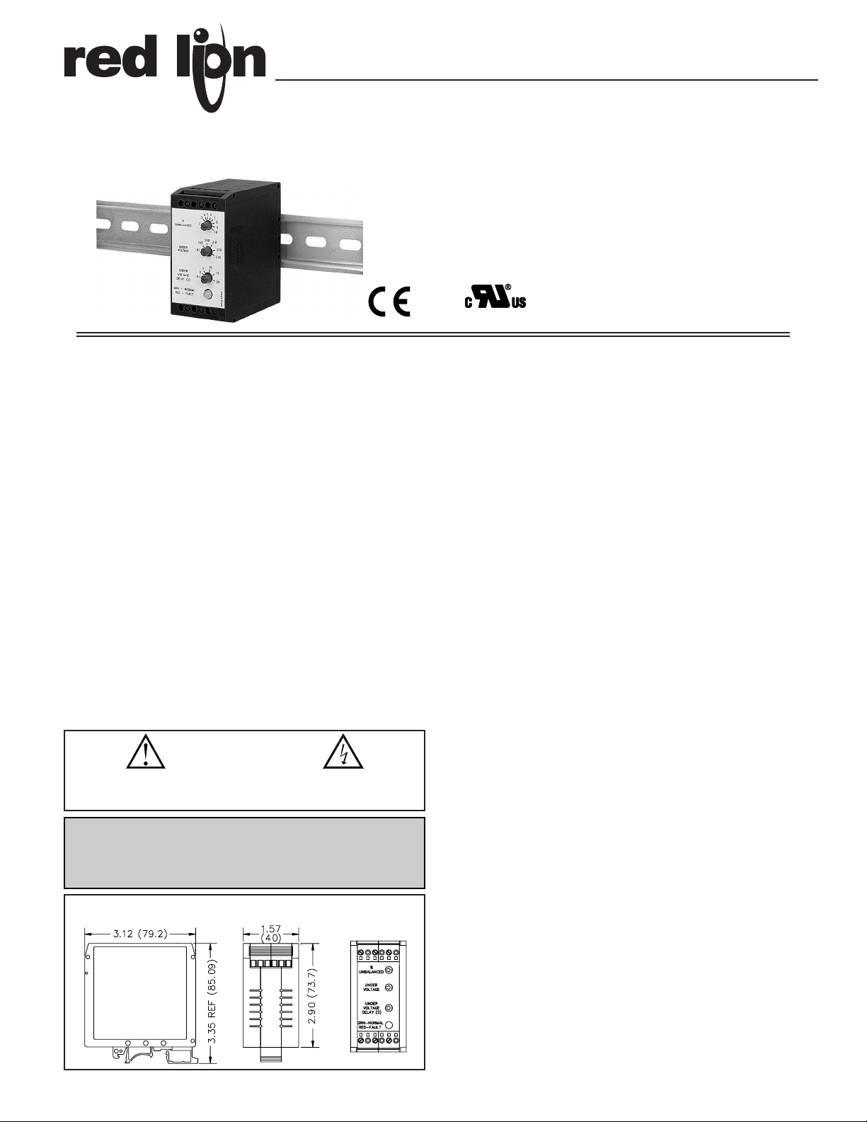
MODEL APMR - 3 PHASE FAULT DETECTION DIN RAIL MODULE
CAUTION: Risk of Danger.
Read complete instructions prior to
installation and operation of the unit.
CAUTION: Risk of electric shock.
DIMENSIONS In inches (mm)
Enclosure class AEN 55011RF interference
Emissions to EN 50081-2
Level 3; 10 V/mENV 50204
150 KHz - 80 MHz
Level 3; 10 V/rms EN 61000-4-6RF conducted interference
Level 3; 2 Kv power
Level 4; 2 Kv I/O EN 61000-4-4Fast transients (burst)
80 MHz - 1 GHz
Level 3; 10 V/m EN 61000-4-3Electromagnetic RF fields
Level 3; 8 Kv air
Level 2; 4 Kv contact EN 61000-4-2Electrostatic discharge
200 Hz, 50% duty cycle
Immunity to EN 50082-2
900 MHz ± 5 MHz
WARNING: 3 Phase Fault Detection Modules must never be used as
“Primary” protection against hazardous operating conditions. Machinery
must first be made safe by inherent design or the installation of guards,
shields, or other devices to protect personnel in the event of a hazardous
machine condition.
Simulation of cordless telephone
UL Recognized Component,
File # E137808
Bulletin No. APMR-E
Drawing No. LP0376
Released 2/07
Tel +1 (717) 767-6511
Fax +1 (717) 764-0839
www.redlion.net
Page 2

2
5. In extremely high EMI environments, the use of external EMI suppression
devices, such as ferrite suppression cores, is effective. Install them on Signal
and Control cables as close to the unit as possible. Loop the cable through the
core several times or use multiple cores on each cable for additional protection.
Install line filters on the power input cable to the unit to suppress power line
interference. Install them near the power entry point of the enclosure. The
following EMI suppression devices (or equivalent) are recommended:
Ferrite Suppression Cores for signal and control cables:
Fair-Rite # 0443167251 (RLC #FCOR0000)
TDK # ZCAT3035-1330A
Steward #28B2029-0A0
Line Filters for input power cables:
Schaffner # FN610-1/07 (RLC #LFIL0000)
Schaffner # FN670-1.8/07
Corcom #1VB3
Corcom #1VR3
Note: Reference manufacturer’s instructions when installing a line filter.
6. Long cable runs are more susceptible to EMI pickup than short cable runs.
Therefore, keep cable runs as short as possible.
WIRING CONNECTIONS
All conductors should meet voltage
and current ratings for each terminal.
Also, cabling should conform to
appropriate standards of good
installation, local codes and regulations.
It is recommended that power supplied to
the unit be protected by a fuse or circuit
breaker. When wiring the unit, use the
number on the label to identify the
position number with the proper
function. Strip wire, leaving
approximately 1/4" (6mm) of bare wire
exposed. Insert the wire into the terminal,
and tighten the screw until the wire is
clamped tightly.
FUNCTION DESCRIPTIONS
PHASE UNBALANCE
Unbalance occurs in 3 phase systems when single phase loads are added
without regard to voltage effects on the remaining phases. This unbalance in
phase voltage causes excessive motor current producing temperatures in excess
of specifications. The relationship between voltage unbalance and percentage
of temperature rise is approximately the square of the percent voltage
unbalance times two. ie., - % temperature rise = (% unbalance2 X 2).
Therefore, a 4% voltage unbalance will result in approximately a 32%
increase in winding temperature. The effect of temperature rise is immediate
failure of winding insulation if unbalance is severe as with single phasing. If
unbalance is slight, gradual winding degradation will result in premature
insulation failure. The APMR will detect slight unbalances that thermal and
magnetic devices usually miss.
PHASE LOSS
Phase Loss is an extreme case of unbalance known as “single phasing”
where a total loss of one of the phases occurs. During this condition the motor
will continue to run and the full current is drawn from the remaining phases.
Unless the motor is lightly loaded motor failure will occur. The APMR will
detect Phase Loss even with regenerated voltages present.
PHASE REVERSAL
Reversing any two of the three phases will cause a motor to rotate opposite
the intended direction causing damage to machinery. Reversal can occur during
maintenance of distribution systems. The APMR will detect Phase Reversal
regardless of load conditions.
UNDERVOLTAGE
Undervoltage can occur during Brownouts, excessive system loading and
motor startups. An undervoltage Time Delay is provided with the undervoltage
detection to eliminate false tripping during startups when a motor draws many
times its operating current.
EMC INSTALLATION GUIDELINES
Although this unit is designed with a high degree of immunity to
ElectroMagnetic Interference (EMI), proper installation and wiring methods
must be followed to ensure compatibility in each application. The type of the
electrical noise, source or coupling method into the unit may be different for
various installations. Cable length, routing and shield termination are very
important and can mean the difference between a successful or a troublesome
installation. Listed below are some EMC guidelines for successful installation
in an industrial environment.
1. The unit should be mounted in a metal enclosure, that is properly connected
to protective earth.
a. If the bezel is exposed to high Electro-Static Discharge (ESD) levels,
above 4 Kv, it should be connected to protective earth. This can be done
by making sure the metal bezel makes proper contact to the panel cut-out
or connecting the bezel screw with a spade terminal and wire to
protective earth.
2. Use shielded (screened) cables for all Signal and Control inputs. The shield
(screen) pigtail connection should be made as short as possible. The
connection point for the shield depends somewhat upon the application.
Listed below are the recommended methods of connecting the shield, in
order of their effectiveness.
a. Connect the shield only at the panel where the unit is mounted to earth
ground (protective earth).
b. Connect the shield to earth ground at both ends of the cable, usually when
the noise source frequency is above 1 MHz.
c. Connect the shield to common of the unit and leave the other end of the
shield unconnected and insulated from earth ground.
3. Never run Signal or Control cables in the same conduit or raceway with AC
power lines, conductors feeding motors, solenoids, SCR controls, and
heaters, etc. The cables should be run in metal conduit that is properly
grounded. This is especially useful in applications where cable runs are long
and portable two-way radios are used in close proximity or if the installation
is near a commercial radio transmitter.
4. Signal or Control cables within an enclosure should be routed as far away as
possible from contactors, control relays, transformers, and other noisy
components.
Page 3

3
SETUP
1. Adjust the dials on the APMR to
the following settings:
a. Under Voltage to minimum
(CCW)
b. Under Voltage Delay to
minimum (CCW)
c. % Unbalanced to maximum
(CW)
2. Connect input wire from the
fused 3 phase line voltage to
Terminals 7 (L1), 9 (L2), and 11
(L3). In Wye systems,
connection to neutral wire is not
required. Do not wire output
contacts until Step 9.
3. TURN POWER ON. When the internal relay energizes, and the Red LED
glows green, the phase sequence is correct and the voltages on all three
phases are above the minimum under voltage setting.
a. If the internal output relay does not energize, and the LED stays red, TURN
POWER OFF and swap any two (2) of the three (3) input wires. This
corrects the phase sequence if the monitor was connected in reverse rotation.
Note: Insure that the motor is wired for correct rotation.
4. Select the proper under voltage trip point. (This is the dial marked Under
Voltage.) The under voltage setting should be the same as the minimum
operating voltage for the equipment to be protected.
Note: If the recommended setting is not known, turn the Undervoltage
adjustment knob CW until the relay de-energizes and the LED glows red.
Turn the knob CCW until the relay energizes and the LED glows green.
This procedure assumes that the line voltages are at an acceptable level
when the adjustments are made.
5. Set the Under Voltage Delay to the desired value. This is the maximum time
period that an under voltage condition can exist before de-energizing the
internal relay. The exact value of the delay depends on the type of equipment
being protected and the quality of the available three phase power. A setting
too low, will cause unnecessary interruptions due to momentary dips in the
line voltage. On the other hand, if the time delay is too long, damage to the
equipment can occur before a legitimate under voltage condition is detected.
Three phase motors have a starting current that is many times higher than
the normal full load current but lasts for only a few seconds. Setting the
delay slightly longer than the duration of this inrush period will prevent the
APMR from being tripped due to a low voltage condition caused by the
starting current.
Note: The under voltage delay applies only to under voltage conditions.
Exceeding the phase unbalance trip setting or a phase loss will deenergize the relay instantly regardless of the delay setting.
6. Phase Unbalance setting. Maximum permissible unbalance and phase
voltages that most three phase powered equipment can tolerate are very
seldom specified. In most locations, three phase voltages typically are not
perfectly balanced. Use your own discretion when setting this value. Too low
of a setting (CCW) can cause unnecessary tripping. Too high of a setting
(CW) does not provide adequate protection.
An alternative procedure is to turn the Unbalance adjustment CCW until the
relay de-energizes and the LED turns red. Turn the knob CW until the relay
energizes and the LED turns green.
Note: This procedure assumes that the line voltages are sufficiently balanced
when the adjustments are made. % Voltage Unbalance is defined by NEMA
as: [(Maximum Deviation From Average Voltage/Average Voltage) X 100]
where Average Voltage = (L1 + L2 + L3)/3.
Note: NEMA recommends not to operate motors with a phase unbalance
greater than 5%.
7. When the phase sequence is correct and the line voltages are within preset
limits, the internal relay of the APMR will energize. The LED indicator
glows green to show a normal condition.
8. TURN POWER OFF. Refer to the wiring diagram for proper output contact
connections.
9. After proper connections are made, TURN POWER ON. The internal relay
energizes allowing the monitored load to become active.
G Rail Installation
To install the APMR on
a “G” style DIN rail,
angle the module so that
the upper groove of the
“foot” catches under the
lip of the top rail. Push the
module toward the rail
until it snaps into place.
To remove a module from
the rail, push up on the
bottom of the module
while pulling out away
from the rail.
T Rail Installation
To install the APMR on a
“T” style rail, angle the
module so that the top
groove of the “foot” is
located over the lip of the
top rail. Push the module
toward the rail until it snaps
into place. To remove a
module from the rail, insert
a screwdriver into the slot on
the bottom of the “foot”, and
pry upwards on the module
until it releases from the rail.
INSTALLATION
The unit is equipped with a universal mounting foot for attachment to standard DIN style
mounting rails, including G profile rail according to EN50035 - G32 , and top hat (T) profile rail
according to EN50022 - 35 x 7.5 and 35 x 15.
The unit should be installed in a location that does not exceed the maximum operating
temperature and provides good air circulation. Placing the unit near devices that generate
excessive heat should be avoided.
Page 4

APPLICATION
A waste water treatment
plant had just completed a
costly repair program,
reconditioning several motors used in their pumping
process. The necessity to rebuild was the direct result
of unbalanced and low voltage supply lines causing
excessive heating to the motor windings. The
continual operation below acceptable levels of power
supply lead to the failure of the motor windings. The
APMR (3 phase fault detector) was included in the
repair program. This upgrade to the system will
automatically shut down the motors if an undesirable
power supply condition is detected. Not only is this a
safeguard against unbalance or low voltage, it will
also detect phase loss or reversal. An alarm will also
trigger in the control room, alerting the operators of
the shut down action.
ORDERING INFORMATION
TROUBLESHOOTING
For further technical assistance, contact technical support at the appropriate company numbers listed.
DESCRIPTION
APMR 3 Phase Fault Detection Module
MODEL NO.
PART NUMBERS FOR
AVAILABLE SUPPLY VOLTAGES
230 VAC
APMR0016
380 VAC
APMR0086
For more information on Pricing, Enclosures & Panel Mount Kits refer to the RLC Catalog or contact your
local RLC distributor.
480 VAC
APMR0096
LIMITED WARRANTY
The Company warrants the products it manufactures against defects in materials and workmanship
for a period limited to two years from the date of shipment, provided the products have been stored,
handled, installed, and used under proper conditions. The Company’s liability under this limited
warranty shall extend only to the repair or replacement of a defective product, at The Company’s
option. The Company disclaims all liability for any affirmation, promise or representation with
respect to the products.
The customer agrees to hold Red Lion Controls harmless from, defend, and indemnify RLC against
damages, claims, and expenses arising out of subsequent sales of RLC products or products
containing components manufactured by RLC and based upon personal injuries, deaths, property
damage, lost profits, and other matters which Buyer, its employees, or sub-contractors are or may be
to any extent liable, including without limitation penalties imposed by the Consumer Product Safety
Act (P.L. 92-573) and liability imposed upon any person pursuant to the Magnuson-Moss Warranty
Act (P.L. 93-637), as now in effect or as amended hereafter.
No warranties expressed or implied are created with respect to The Company’s products except those
expressly contained herein. The Customer acknowledges the disclaimers and limitations contained
herein and relies on no other warranties or affirmations.
Red Lion Controls
20 Willow Springs Circle
York PA 17406
Tel +1 (717) 767-6511
Fax +1 (717) 764-0839
Red Lion Controls AP
31, Kaki Bukit Road 3,
#06-04/05 TechLink
Singapore 417818
Tel +65 6744-6613
Fax +65 6743-3360
Red Lion Controls BV
Basicweg 11b
NL - 3821 BR Amersfoort
Tel +31 (0) 334 723 225
Fax +31 (0) 334 893 793
 Loading...