

Page 1

714FX6
Managed Industrial
Ethernet Switch
User Manual &
Installation
Guide
(Revised 2015-09-28) Page 1 of 161
Page 2

714FX6 Industrial Ethernet Switch Installation Guide ................................................................................................ 5
714FX6 Industrial Ethernet Switch Accessories .......................................................................................................... 7
SAFETY WARNINGS ................................................................................................................................................ 9
SUPPORT: ................................................................................................................................................................... 9
Installation .................................................................................................................................................................. 11
DIN RAIL MOUNTING............................................................................................................................................ 12
FRONT PANEL (714FX6) ........................................................................................................................................ 13
APPLYING POWER (Top View) ............................................................................................................................. 14
Connecting the Unit ................................................................................................................................................... 15
Overview of Advanced Features ................................................................................................................................ 19
Mode of Operation .................................................................................................................................................................. 19
Port Mirroring ......................................................................................................................................................................... 19
Port Trunking .......................................................................................................................................................................... 19
Quality of Service (QoS) ......................................................................................................................................................... 19
Virtual LAN ............................................................................................................................................................................ 20
Rapid Spanning Tree Protocol ................................................................................................................................................ 21
SNMP Traps ................................ ................................................................................................................................ ............ 21
IGMP Snooping ...................................................................................................................................................................... 21
N-Ring ..................................................................................................................................................................................... 22
N-Link ..................................................................................................................................................................................... 22
CIP .......................................................................................................................................................................................... 22
DHCP ...................................................................................................................................................................................... 22
DHCP Client ........................................................................................................................................................................... 23
DHCP Relay Agent ................................................................................................ ................................ ................................. 23
DHCP Server ........................................................................................................................................................................... 23
LLDP ....................................................................................................................................................................................... 23
Port Security—MAC Address Based ...................................................................................................................................... 23
TROUBLESHOOTING .......................................................................................................................................................... 24
Web Software Configuration ..................................................................................................................................... 25
Web Management ................................................................................................................................................................... 25
Web Management - Home ...................................................................................................................................................... 26
Administration – System ......................................................................................................................................................... 28
Administration – SNMP .......................................................................................................................................................... 32
Administration – Fault ............................................................................................................................................................ 34
DHCP – Server – Setup Profiles ............................................................................................................................................. 36
DHCP – Server – Setup IP Maps ............................................................................................................................................ 38
DHCP – Server – View Bindings ............................................................................................................................................ 43
DHCP – Relay & Local IP - Setup .......................................................................................................................................... 44
LLDP - Configuration ............................................................................................................................................................. 47
LLDP - Ports ........................................................................................................................................................................... 48
LLDP - Status .......................................................................................................................................................................... 49
LLDP - Statistics ..................................................................................................................................................................... 50
Ports – Configuration .............................................................................................................................................................. 51
Ports – MAC Security – Learning ........................................................................................................................................... 54
Ports – MAC Security – Authorization List ............................................................................................................................ 57
Ports – MAC Security – Intruder Log ..................................................................................................................................... 58
Ports – Mirroring ..................................................................................................................................................................... 59
Ports – Trunking ...................................................................................................................................................................... 61
Ports – QOS............................................................................................................................................................................. 62
Statistics – Port Statistics ........................................................................................................................................................ 64
Statistics – Port Utilization ...................................................................................................................................................... 65
VLAN – Configuration ........................................................................................................................................................... 66
Bridging – Aging Time ........................................................................................................................................................... 68
Bridging – Unicast Addresses ................................................................................................................................................. 69
Bridging – Multicast Addresses .............................................................................................................................................. 71
Bridging – Show MAC by Port ............................................................................................................................................... 73
RSTP – Configuration ............................................................................................................................................................. 75
IGMP – Configuration ............................................................................................................................................................ 79
IGMP – RFilter ....................................................................................................................................................................... 84
(Revised 2015-09-28) Page 2 of 161
Page 3

N-View – Configuration .......................................................................................................................................................... 86
N-View – Ports ........................................................................................................................................................................ 87
N-Ring – Configuration .......................................................................................................................................................... 89
N-Ring – Advanced Configuration ......................................................................................................................................... 92
N-Ring – Status ....................................................................................................................................................................... 94
N-Link – Configuration ................................................................................................................................ ........................... 98
N-Link – Status ..................................................................................................................................................................... 102
CIP – Configuration .............................................................................................................................................................. 107
CIP – Status ................................................................................................................................................................ ........... 108
Firmware/Config – TFTP ...................................................................................................................................................... 109
Support – Web Site and E-mail ............................................................................................................................................. 110
BPCL – Broadcast Packet Count Limit Configuration ......................................................................................................... 111
User Management – Adding Users ....................................................................................................................................... 112
User Management – Removing Users ................................................................................................................................... 113
LogicalView .......................................................................................................................................................................... 114
Configuration – Save or Reset............................................................................................................................................... 115
Help – Overview ................................................................................................................................................................... 117
Help – Administration ........................................................................................................................................................... 118
Help – DHCP ........................................................................................................................................................................ 119
Help – LLDP ......................................................................................................................................................................... 120
Help – Ports ................................................................................................................................................................ ........... 121
Help – Statistics ..................................................................................................................................................................... 122
Help – VLAN ........................................................................................................................................................................ 123
Help – Bridging ..................................................................................................................................................................... 124
Help – RSTP ......................................................................................................................................................................... 125
Help – IGMP ......................................................................................................................................................................... 126
Help – N-View ...................................................................................................................................................................... 127
Help – N-Ring ....................................................................................................................................................................... 128
Help – N-Link ....................................................................................................................................................................... 129
Help – CIP ............................................................................................................................................................................. 130
Help – Firmware/Config ....................................................................................................................................................... 131
Help – BPCL ......................................................................................................................................................................... 132
Help – User Management ...................................................................................................................................................... 133
Help – Other .......................................................................................................................................................................... 134
CLI Commands ........................................................................................................................................................ 135
“?” (Help) .............................................................................................................................................................................. 135
Logout ................................................................................................................................................................................... 135
Show, Add, or Delete ARL Entries ....................................................................................................................................... 136
Configuration Device Operations .......................................................................................................................................... 137
Show or Set CIP Configuration ............................................................................................................................................. 138
Save or Reset the Configuration Settings .............................................................................................................................. 139
Show or Set IGMP Configuration ......................................................................................................................................... 139
Show or Set Mirror Configuration ........................................................................................................................................ 140
Show or Set N-Ring Configuration ....................................................................................................................................... 141
Show or Set N-View Configuration ...................................................................................................................................... 141
Ping a Host ............................................................................................................................................................................ 142
Show or Set Port Configuration ............................................................................................................................................ 143
Reset the Switch .................................................................................................................................................................... 144
Show or Set SNMP Configuration ........................................................................................................................................ 144
Show or Clear the Last System Error ................................................................................................ .................................... 145
Show System Information ..................................................................................................................................................... 145
Set or Show the System IP Configuration ............................................................................................................................. 146
Show or Set System Configuration ....................................................................................................................................... 147
VLAN Addition and Deletion Example ................................................................................................................... 148
VLAN Configuration Examples .............................................................................................................................. 153
Example 1 – Basic understanding of port-based VLANs ...................................................................................................... 153
Example 2 – Basic understanding of tagged VLANs (Admit – Tagged Only) ..................................................................... 154
Example 3 – Basic understanding of tagged VLANs (Admit – All) ..................................................................................... 155
Example 4 – Basic understanding of Hybrid VLANs ........................................................................................................... 156
Example 5 – Basic understanding of Overlapping VLANs................................................................................................... 157
Example 6 – Basic understanding of VLANs with Multicast Filtering ................................................................................. 158
(Revised 2015-09-28) Page 3 of 161
Page 4

KEY SPECIFICATIONS (714FX6) ........................................................................................................................ 159
N-TRON Limited Warranty ..................................................................................................................................... 161
(Revised 2015-09-28) Page 4 of 161
Page 5
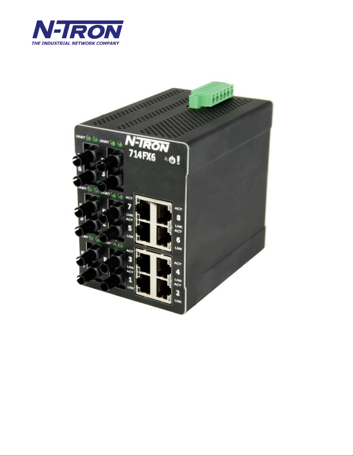
714FX6 Industrial Ethernet Switch Installation Guide
The N-TRON 714FX6 Industrial Ethernet Switch offers outstanding performance and ease of use. It is
ideally suited for connecting Ethernet enabled industrial and or security equipment and is a fully managed
switch.
(Revised 2015-09-28) Page 5 of 161
Page 6

PRODUCT FEATURES
• Full IEEE 802.3 Compliance
• Eight 10/100 BaseTX RJ-45 Ports
• Six 100BaseFX(E) Ports
• Extended Environmental Specifications (Surrounding
Air) -40 to 70 ºC Operating temperature
• ESD and Surge Protection Diodes on all Ports
• Auto Sensing 10/100BaseTX, Duplex, and MDIX
• Offers Rapid Spanning Tree Protocol
• Store & Forward Technology
• Rugged Din-Rail Enclosure
• Onboard Temperature Sensor
• Configuration Backup via optional SD Card
(NTCD-128)
• Redundant Power Inputs 10-49VDC (Regulated)
PRODUCT CONFIGURATIONS
• 714FX6-XX and 714FXE6-XX-YY
– Eight 10/100 Base-TX RJ45 Copper Ports,
Six 100BaseFX Ports,
Where: XX = ST or SC
YY = 10, 40 or 80 for Singlemode, Blank for Multimode
E = Singlemode, Blank Otherwise
MANAGEMENT FEATURES
• SNMP v1, v2, v3 and Web Browser Management
• Configuration backup via Optional Configuration Device (NTCD)
• EtherNet/IP™ CIP Messaging
• Detailed Ring Map and Fault Location Charting
• N-Ring™ Technology with ~30ms Healing
• Web Browser Management with detailed ring map and
fault location charting.
• N-View™ OPC Monitoring
• N-Link™ Redundant N-Ring Coupling
• IGMP Auto Configuration and Plug and Play Support
• 802.1Q tag VLAN and Port VLAN
• 802.1p QoS, Port QoS, and DSCP
• LLDP (Link Layer Discovery Protocol)
• Trunk with other N-Tron trunking capable switches over two ports
• Port Mirroring
• 802.1d, 802.1w, 802.1D RSTP (Rapid Spanning Tree Protocol)
• DHCP Client, Server, Option 82 relay, Option 61
• Local Port IP Addressing
• Port Security—MAC Address Based
Copyright, © N-Tron Corp., 2008-2015
(Revised 2015-09-28) Page 6 of 161
Page 7
714FX6 Industrial Ethernet Switch Accessories
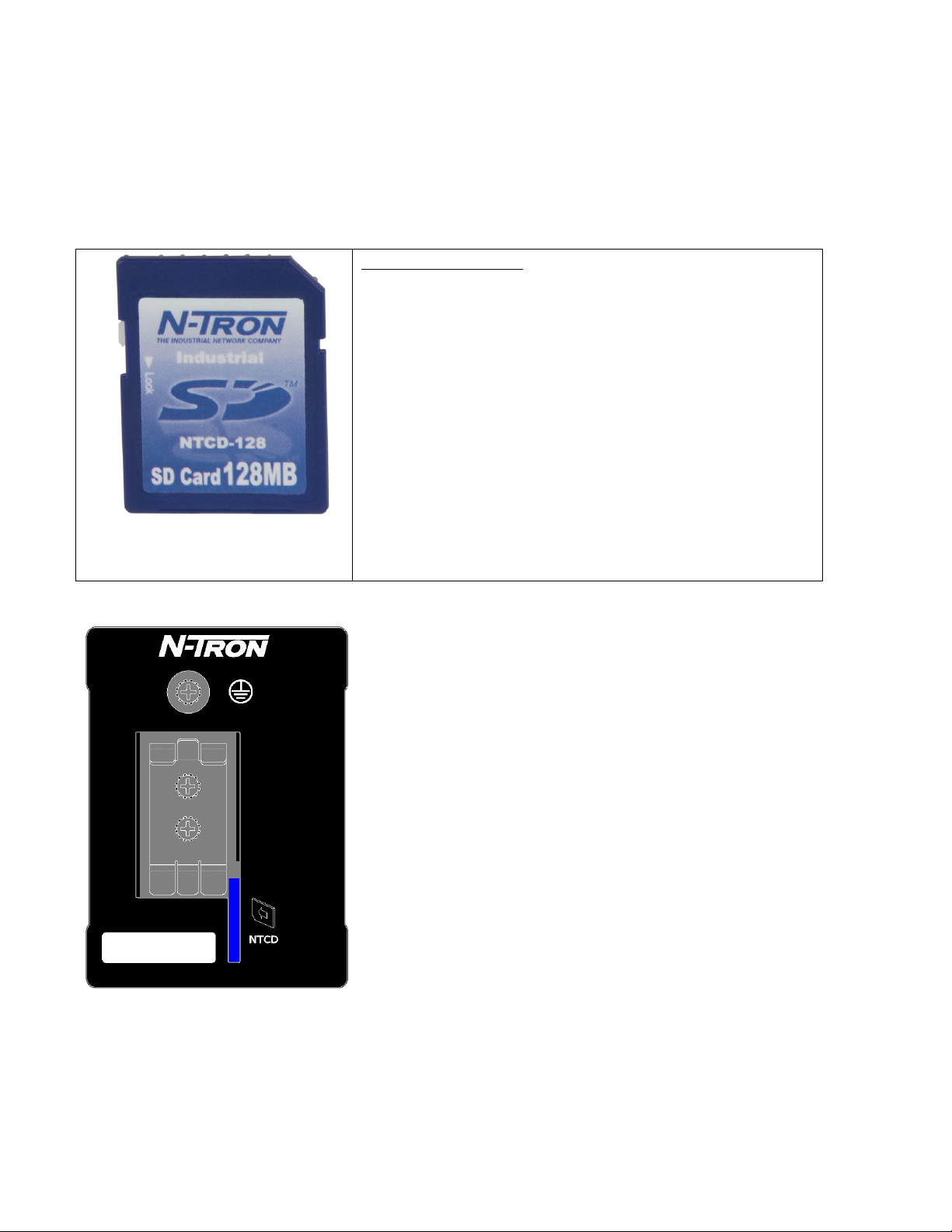
NTCD-128
Configuration Device
Ideal for saving, or restoring switch configuration
parameters quickly without the need for a computer or
software. One configuration device per switch is
recommended.
The SD and USB connectors are for temporary connection only. Do not use, connect, or disconnect unless
area is known to be non-hazardous. Connection or disconnection in an explosive atmosphere could result in
an explosion.
Les SD et USB sont pour la connexion temporaire. Ne pas utiliser, de connecter ou déconnecter sauf si la
zone est connue pour être non dangereux. Connexion ou la déconnexion dans une atmosphère explosive
pourrait entraîner une explosion.
The NTCD configuration device is inserted in the back of the 714FX6.
(Revised 2015-09-28) Page 7 of 161
Page 8

Copyright, © N-Tron Corp., 2008-2013
3101 International Drive, Building 6
Mobile, AL 36606 USA
All rights reserved. Reproduction, adaptation, or translation without prior written permission from N-Tron
Corporation is prohibited, except as allowed under copyright laws.
Ethernet is a registered trademark of Xerox Corporation. All other product names, company names, logos
or other designations mentioned herein are trademarks of their respective owners.
The information contained in this document is subject to change without notice. N-Tron Corporation makes
no warranty of any kind with regard to this material, including, but not limited to, the implied warranties of
merchantability or fitness for a particular purpose. In no event shall N-Tron Corporation be liable for any
incidental, special, indirect, or consequential damages whatsoever included but not limited to lost profits
arising out of errors or omissions in this manual or the information contained herein.
WARNING
ALERTE
Do not perform any services on the unit unless qualified to do so. Do not substitute unauthorized parts or
make unauthorized modifications to the unit.
Ne pas effectuer de services sur l'appareil s'il n'est pas qualifié pour le faire. Ne pas remplacer les pièces non
autorisées ou de modifications non autorisées de l'appareil.
Do not operate the unit with the top cover removed, as this could create a shock or fire hazard.
Ne pas faire fonctionner l'unité avec le couvercle retiré, ce qui pourrait créer une décharge électrique ou un
incendie.
Do not block the air vents on the sides or the top of the unit.
N'obstruez pas les fentes d'aération sur les côtés ou en haut de l'unité.
Do not operate the equipment in the presence of flammable gasses or fumes. Operating electrical equipment
in such an environment constitutes a definite safety hazard.
Ne pas utiliser le matériel en présence de gaz ou de vapeurs inflammables. L'utilisation de matériel électrique
dans un tel environnement constitue un danger certain.
Do not operate the equipment in a manner not specified by this manual.
Ne pas utiliser le matériel en présence de gaz ou de vapeurs inflammables. L'utilisation de matériel électrique
dans un tel environnement constitue un danger certain.
Do not service the equipment without first disconnecting the power connector.
Ne pas réparer l'équipement sans d'abord débrancher le connecteur d'alimentation.
(Revised 2015-09-28) Page 8 of 161
Page 9

SAFETY WARNINGS
AVERTISSEMENTS DE SÉCURITÉ
GENERAL SAFETY WARNINGS
GÉNÉRAL AVERTISSEMENTS DE SÉCURITÉ
WARNING: If the equipment is used in the manner not specified by N-Tron Corporation, the protection
provided by the equipment may be impaired.
ALERTE: Si l'équipement est utilisé d'une manière non spécifiée par N-Tron Corporation, la protection
fournie par l'équipement peut être compromise.
WARNING: Do not service the equipment without first disconnecting the power connector.
ALERTE: Ne pas réparer l'équipement sans d'abord débrancher le connecteur d'alimentation.
LASER SAFETY (Single Mode Fiber Models -40 and -80)
CAUTION: CLASS 1 LASER PRODUCT. Do not stare into the laser!
ATTENTION: PRODUIT LASER CLASSE 1. Ne pas regarder dans le laser!
SUPPORT:
Contact Information
N-Tron Corporation
3101 International Drive, Building 6
Mobile, AL 36606 USA
TEL: (251) 342-2164
FAX: (251) 342-6353
WEBSITE: www.redlion.net
E-MAIL: customer.service@redlion.net
ENVIRONMENTAL SAFETY
WARNING: Disconnect the power and allow to cool 5 minutes before touching.
ALERTE: Déconnectez le câble d'alimentation et laisser refroidir 5 minutes avant de la toucher.
ELECTRICAL SAFETY
Must be powered by a Class 2 source only.
Doit être alimenté par une source de Classe 2 seulement.
(Revised 2015-09-28) Page 9 of 161
Page 10

WARNING: Disconnect the power cable before removing any enclosure panel.
ALERTE: Débrancher le câble d'alimentation avant de retirer le panneau du chassis.
WARNING: Do not operate the unit with the any cover removed.
ALERTE: Ne pas utiliser l'appareil avec n'importe quel couvercle retiré.
WARNING: Properly ground the unit before connecting anything else to the unit. Units not properly
grounded may result in a safety risk and could be hazardous and may void the warranty. See the grounding
technique section of this user manual for proper ways to ground the unit.
ALERTE: Correctement à la terre de l'unité avant tout raccordement à l'unité. Unités pas correctement mise
à la terre peut entraîner un risque de sécurité et pourraient être dangereux et peut annuler la garantie. Voir la
section technique de mise à la terre de ce mode d'emploi des moyens appropriés à la masse de l'appareil.
WARNING: Never install or work on electrical equipment or cabling during periods of lightning activity.
ALERTE: Ne jamais installer ou de travailler sur un équipement électrique ou de câblage pendant les
périodes d'activité de la foudre.
WARNING: Do not perform any services on the unit unless qualified to do so.
ALERTE: Ne pas effectuer de services sur l'appareil s'il n'est pas qualifié pour le faire.
WARNING: Do not block the air vents.
ALERTE: Ne pas obstruer les bouches d'aération.
WARNING: Observe proper DC Voltage polarity when installing power input cables. Reversing voltage
polarity can cause permanent damage to the unit and void the warranty.
ALERTE: Respecter la polarité correcte de tension DC lors de l'installation des câbles d'alimentation
d'entrée. Inversion de polarité de tension peut causer des dommages permanents à l'appareil et annule la
garantie.
Hazardous Location Installation Requirements
1. This equipment is suitable for use in Class I, Div. 2, Groups A, B, C, D or non-hazardous locations
only.
Cet équipement est adapté pour une utilisation dans la classe I, Division 2, Groupes A, B, C et D ou
non dangereux endroits seulement.
2. WARNING: Explosion Hazard – Substitution of components may impair suitability for Class I,
Division 2.
ALERTE: Risque d'explosion - Remplacement d'un composant peut empêcher la conformité de
Classe I, Division 2.
3. WARNING: Explosion Hazard - Do not connect or disconnect any connections while circuit is live
unless area is known to be non-hazardous.
ALERTE: Risque d'explosion - Ne pas brancher ou débrancher les connexions lorsque le circuit est
sous tension sauf si la zone est connue pour être non dangereux.
4. WARNING: Explosion Hazard – Do not replace the device unless power has been switched off or
the area is known to be non-hazardous.
ALERTE: Risque d'explosion - Ne pas remplacer le périphérique à moins que l'alimentation a été
coupé ou que la zone est connu pour être non dangereux.
(Revised 2015-09-28) Page 10 of 161
Page 11

5. Use 90°C or higher rated Copper wire, (0.22Nm) 2lb/in tightening torque for field installed
conductors.
Utilisez 90° C ou plus classé fil de cuivre, (0.22Nm) 2lb/in couple de serrage des conducteurs
installés sur le terrain.
6. WARNING: Exposure to some chemicals may degrade the sealing properties of materials used in
the Sealed Relay Device. Relays U13 and U25.
AVERTISSEMENT: L'exposition à certains produits chimiques peut dégrader les propriétés
d'étanchéité des matériaux utilisés dans le dispositif de relais scellé. Relais U13 et U25.
Please make sure the 714FX6 Series Ethernet Switch package contains the following items:
1. 714FX6 Series Switch
2. Product CD
Contact your carrier if any items are damaged.
Installation
Read the following warning before beginning the installation:
Read the following warning before beginning the installation:
Lire l'avertissement suivant avant de commencer l'installation:
WARNING
ALERTE
Never install or work on electrical equipment or cabling during periods of lightning activity. Never connect
or disconnect power when hazardous gasses are present.
Ne jamais installer ou de travailler sur un équipement électrique ou de câblage pendant les périodes
d'activité de la foudre. Ne jamais brancher ou débrancher l'alimentation en gaz dangereux sont présents.
Disconnect the power cable before removing any enclosure panel.
Débrancher le câble d'alimentation avant de retirer le panneau du chassis.
UNPACKING
Remove all the equipment from the packaging, and store the packaging in a safe place. File any damage
claims with the carrier.
CLEANING
Clean only with a damp cloth.
(Revised 2015-09-28) Page 11 of 161
Page 12
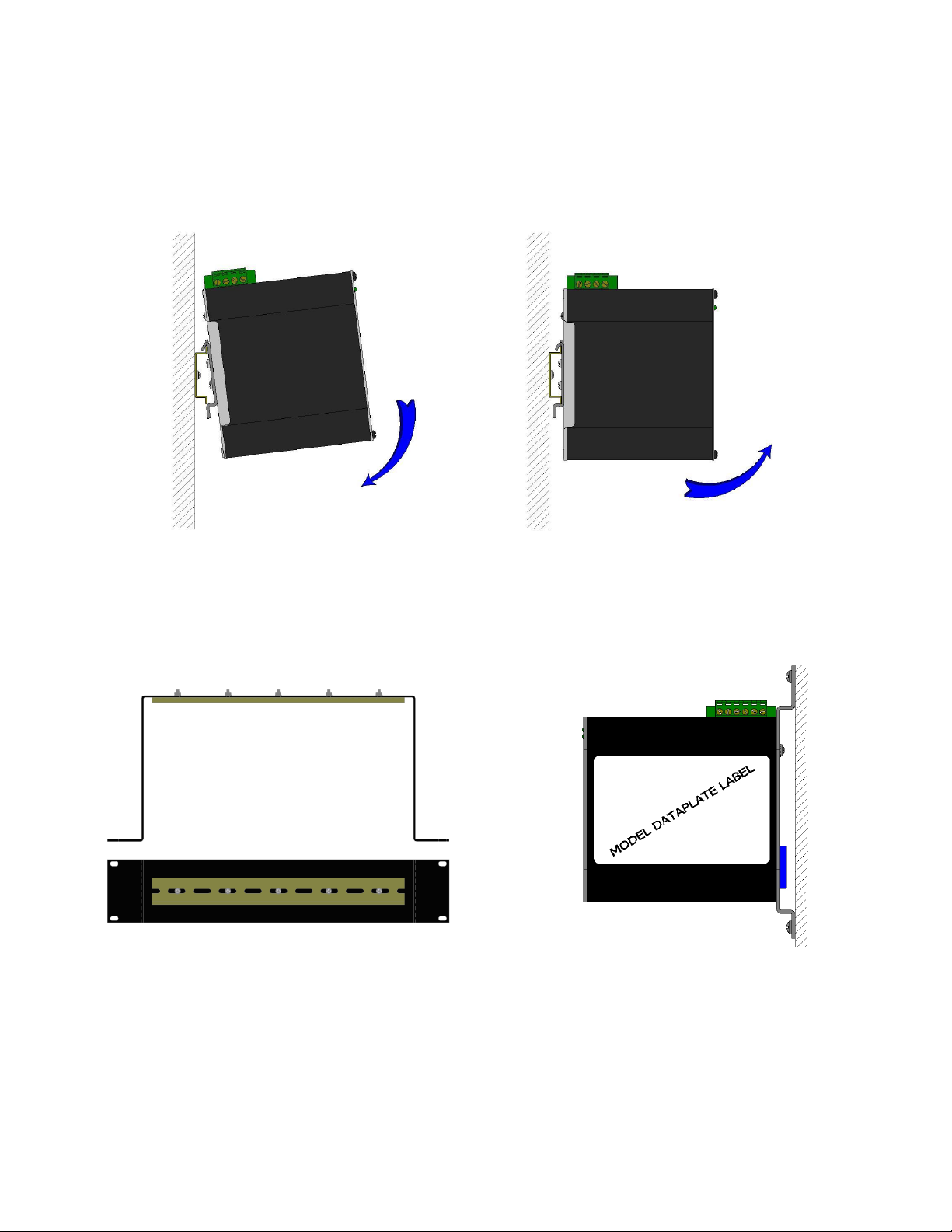
To install the unit to 35mm industrial DIN rail,
place the top edge of the included mounting
bracket on the back of the unit against the DIN rail
at a 15° angle as shown. Rotate the bottom of the
unit to the back (away from you) until it snaps into
place.
To remove the unit from the 35mm industrial
DIN rail, pull forward on the unit until it disengages
from the bottom of the DIN rail. Rotate the bottom
of the unit towards you and up at an approximate
15° upward angle to completely remove the unit.
DIN RAIL MOUNTING
Install the unit on a standard 35mm Din-Rail. Recess the unit to allow at least 3” of horizontal clearance for
copper cable bend radius. Recess the unit to allow at least 5” of horizontal clearance for fiber cable bend
radius. There should be at least 3” of clearance on both the top and bottom of the unit to allow proper
ventilation.
URMK CPMA-2
Most N-Tron™ products are designed to be mounted on industry standard 35mm DIN rail. However, DIN
rail mounting may not be suitable for all applications. Our Optional Universal Rack Mount Kit (P/N:
URMK) may be used to mount the enclosure to standard 19" racks, and our Optional Factory Installed Panel
Mount Assembly (P/N: CPMA-2) may be used to mount the enclosure to a panel or any other flat surface.
(Revised 2015-09-28) Page 12 of 161
Page 13
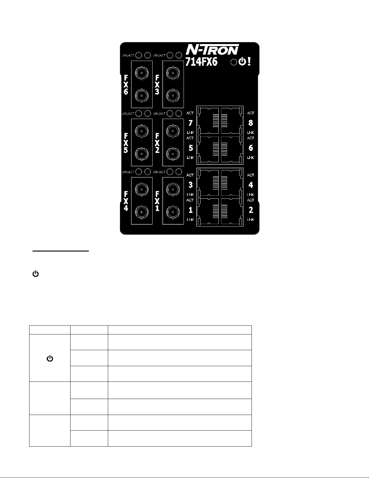
FRONT PANEL (714FX6)
LED
Color
Description
GREEN
Power is ON
RED
Power is ON and a fault condition exists
OFF
Power is OFF
LNK
GREEN
10/100Mb Link between ports
OFF
No Link between ports
ACT
GREEN
Data is active between ports
OFF
Data is inactive between ports
From Top to Left:
RJ45 Ports Auto Sensing 10/100 Base-TX Connections
Fiber Ports 100 Base-FX Connections
LED lights when Power is supplied to the unit
NOTE: The RJ45 data port has two LEDs located on each connector. The left LED indicates LINK status,
and the right LED indicates ACTIVITY.
LEDs: The table below describes the operating modes:
(Revised 2015-09-28) Page 13 of 161
Page 14
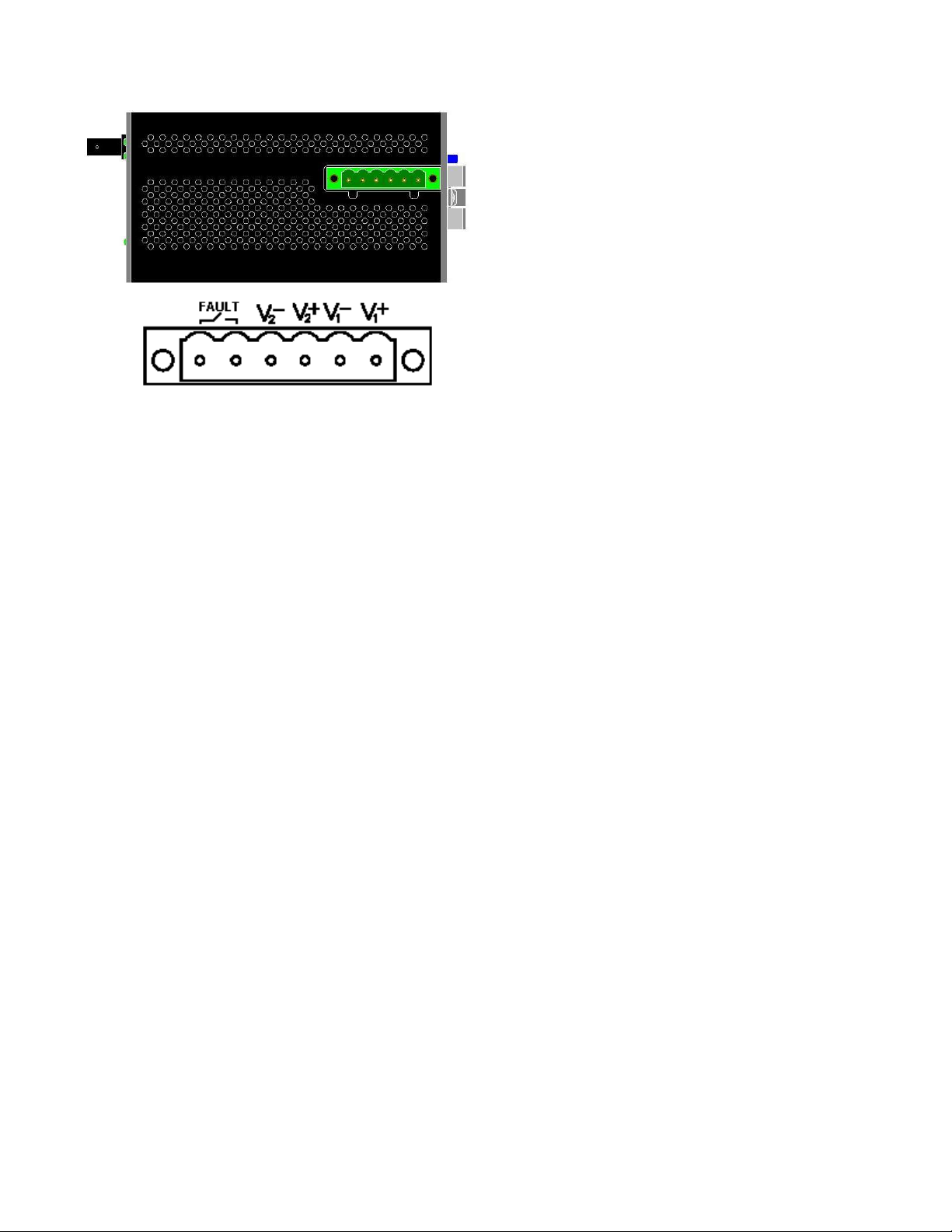
APPLYING POWER (Top View)
Input AC 115/230V
Output DC 24-28V
Output Current 1.3A @ 24V
1.0A @ 28V
Power 30W
35 mm DIN-Rail Mountable
Dimensions: 45X75X91 mm
Unscrew & Remove the DC Voltage Input
Plug from the Power Input Header
Install the DC Power Cables into the Plug
(observing polarity).
Plug the Voltage Input Plug back into the
Power Input Header.
Tightening torque for the terminal block
power plug is 0.5 Nm/0.368 Pound Foot.
Verify the Power LED stays ON (GREEN).
Notes:
Only 1 power supply must be connected to power for minimal operation. For redundant power
operation, V1 and V2 inputs must be connected to separate DC Voltage sources. This device will
draw current from both sources simultaneously. Use 16-28 gauge wire when connecting to the
power supply.
The Fault pins on the power connector can be used for an alarm contact. The current carrying
capacity is 1A at 24VDC. It is normally open and the relay closes when a fault condition occurs.
These pins can be used to connect an external warning device such as a light in order to provide an
external alarm. The conditions for generating a fault condition (closing the relay) can be configured
through software.
Recommended 24V DC Power Supplies, similar to: N-Tron’s P/N NTPS-24-1.3 (NOTE: Not appropriate
for use with M12, POE, and HV models.):
(Revised 2015-09-28) Page 14 of 161
Page 15
Connecting the Unit
For FX/FXE units, remove the dust cap from the fiber optic connectors and connect the fiber optic cables.
The TX port (located on the bottom connector) on the FX/FXE models should be connected to the RX port of the
far end station. The RX port (located on the top connector) on the FX/FXE versions should be connected to the
TX port of the far end station.
For 10/100 Base-TX ports, plug a Category 5E twisted pair cable into the RJ45 connector. Connect the
other end to the far end station. Verify that the LNK LEDs are ON once the connection has been completed.
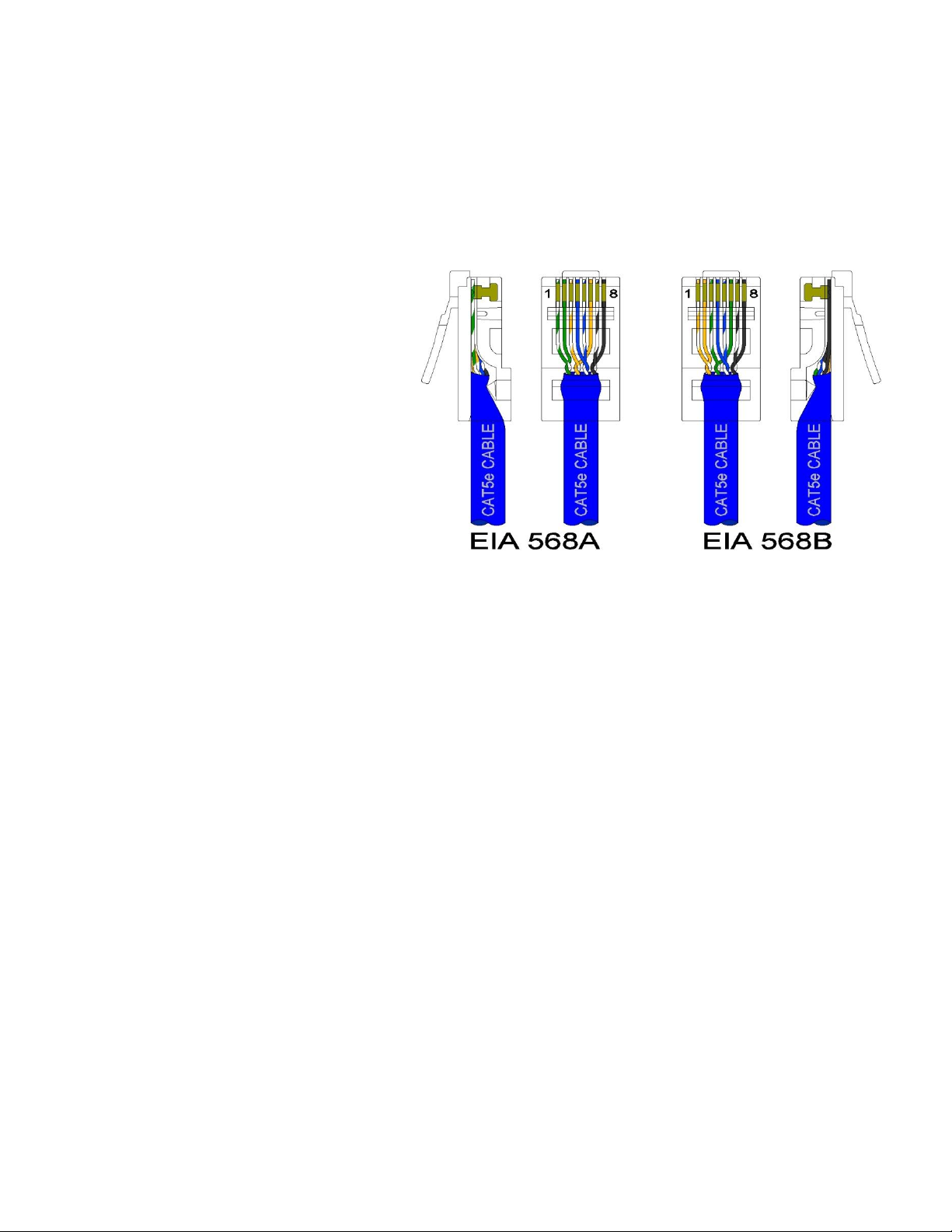
To connect any port to another device (end node, Switch or Repeater), use a standard Category 5E straight
through or crossover cable with a
minimum length of one meter and a
maximum length of 100 meters.
N-Tron recommends the use of premanufactured Cat5E cables to ensure the
best performance. If this is not an option
and users must terminate their own ends
on the Cat5E cables; one of the two color
coded standards shown to the right should
be utilized. If a user does not follow one
of these two color code standards then the
performance and maximum cable distance
will be reduced significantly, and may
prevent the switch from establishing a
link.
Warning: Creating a port to port connection on the same switch (i.e. loop) is an illegal operation and
will create a broadcast storm which will crash the network!
(Revised 2015-09-28) Page 15 of 161
Page 16
N-TRON SWITCH GROUNDING TECHNIQUES
The grounding philosophy of any control system is an integral part of the design. N-Tron switches are
designed to be grounded, but the user has been given the flexibility to float the switch when required. The
best noise immunity and emissions (i.e. CE) are obtained when the N-Tron switch chassis is connected to
earth ground via a drain wire. Some N-Tron switches have metal din-rail brackets that can ground the
switch if the din-rail is grounded. In some cases, N-Tron switches with metal brackets can be supplied with
optional plastic brackets if isolation is required.
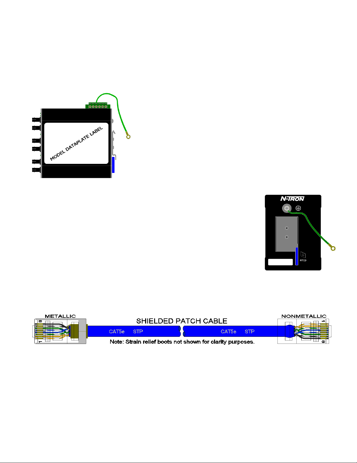
Both V- legs of the power input connector are connected to chassis
internally on the PCB. Connecting a drain wire (shown in green) to
earth ground from one of the V- terminal plugs as shown here will
ground the switch and the chassis. The power leads from the power
source should be limited to 3 meters or less in length.
As an alternate, users can run a drain wire (shown in green) & lug from any of
the Din-Rail screws or empty PEM nuts on the enclosure. When using an
unused PEM nut to connect a ground lug via a machine screw, care should be
taken to limit the penetration of the outer skin by less than 1/4 in. Failure to do
so may cause irreversible damage to the internal components of the switch.
Note: Before applying power to the grounded switch, you must use a volt meter
to verify there is no voltage difference between the power supply’s negative
output terminal and the switch chassis grounding point.
If the use of shielded cables is required, it is generally recommended to only connect the shield at one end to
prevent ground loops and interfere with low level signals (i.e. thermocouples, RTD, etc.). Cat5e cables
manufactured to EIA-568A or 568B specifications are required for use with N-Tron Switches.
In the event all Cat5e patch cable distances are small (i.e. All Ethernet devices are located in the same local
cabinet and/or referenced to the same earth ground), it is permissible to use fully shielded cables terminated
to chassis ground at both ends in systems void of low level analog signals.
(Revised 2015-09-28) Page 16 of 161
Page 17
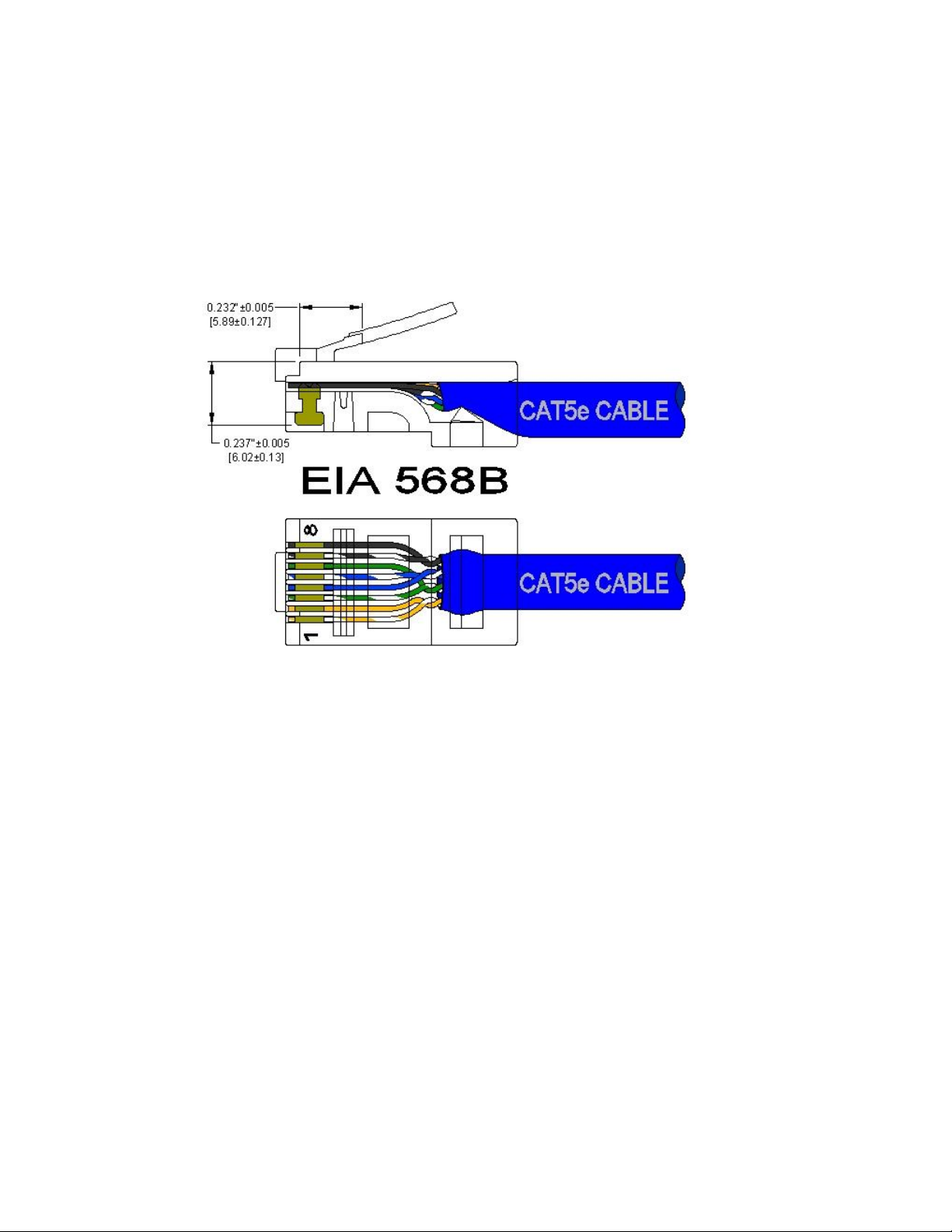
RJ45 CONNECTOR CRIMP SPECIFICATIONS
Please reference the illustration below for your Cat5 cable specifications:
(Revised 2015-09-28) Page 17 of 161
Page 18
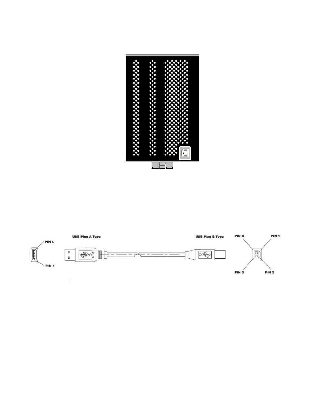
USB INTERFACE
The 714FX6 Series switches provide a USB interface accessed via the USB connector labeled as “USB” on
the unit. This is used to access the Command Line Interpreter (CLI).
The USB connector is at the bottom of the 714FX6.
USB Cable
Connect the USB port of your PC and the Switch using a standard USB cable. You will require a cable with
a Type A connector for the PC end, and a Type B connector for the Switch end.
Standard USB cables are readily available from a variety of computer stores.
HyperTerminal
The following configuration should be used in HyperTerminal:
Port Settings: 115200
Data Bits: 8
Parity: NONE
Stop bits: 1
Flow Control: NONE
(Revised 2015-09-28) Page 18 of 161
Page 19

Overview of Advanced Features
Mode of Operation
Each port on the switch can be configured into different modes of operation as shown below:
Copper Ports: 100Base Fiber Ports: 1000Base Copper/Fiber Ports:
- Half Duplex - Full Duplex - Full Duplex
- Full Duplex
- Auto Negotiation
Half Duplex
In half duplex mode, the CSMA/CD media access method is the means by which two or more stations share
a common transmission medium. To transmit, a station waits (defers) for a quiet period on the medium (that
is, no other station is transmitting) and then sends the intended message in bit-serial form. If, after initiating
a transmission, the message collides with that of another station, then each transmitting station intentionally
transmits for an additional predefined period to ensure propagation of the collision throughout the system.
The station remains silent for a random amount of time (back-off) before attempting to transmit again.
Full Duplex
Full duplex operation allows simultaneous communication between a pair of stations using point-to-point
media (dedicated channel). Full duplex operation does not require that transmitters defer, nor do they
monitor or react to receive activity, as there is no contention for a shared medium in this mode.
Auto Negotiation
In Auto Negotiation mode, the port / hardware detects the mode of operation of the station that is connected
to this port and sets its mode to match the mode of the station.
Port Mirroring
A Mirroring Port is a dedicated port that is configured to receive the copies of Ethernet frames that are being
transmitted out and also being received in from any other port that is being monitored.
Port Trunking
Port Trunking is the ability to group two network ports to increase the bandwidth between two machines
(switch or any work station). This feature allows grouping of high-speed connectivity and provides
redundant connection between switches, so that a trunk can act as a single link between the switches.
Quality of Service (QoS)
Quality of service (QoS) refers to resource reservation control mechanisms. Quality of service is the ability
to provide different priority to different applications, users, or data flows. Quality of service guarantees are
important if the network capacity is insufficient, especially for real-time streaming multimedia applications
such as voice over IP, online games and IP-TV, since these often require fixed bit rate and are delay
sensitive, and in networks where the capacity is a limited resource, for example in cellular data
communication. In the absence of network congestion, QoS mechanisms are not required.
(Revised 2015-09-28) Page 19 of 161
Page 20

Each of these three QOS methods below is included or not based on the settings on the relevant browser
page:
1) Force High Priority (Port Based),
2) IEEE802.1p (Tagged QOS), or
3) DSCP (differentiated services code points) (RFC 2474).
When Force High Priority is enabled, the port based priority is included in the decision for all ports and all
frames received on a port will use the default QOS priority for that port in the decision. For example, if it is
desired to have ingress frames on a port egress to the highest priority transmit queue regardless of other
factors, then enable Force High Priority and set the port's Default Port Priority to 7.
Virtual LAN
The switch provides support for setting up tagged Virtual LANs (Local Area Networks). A port may belong
to any number of Virtual LANs. The VLAN membership of a device is determined by the VLAN(s) that
have been defined for the port to which the device is connected. If a device should move from one port to
another, it loses its current VLAN membership and inherits that of the new port it is connected to.
VLANs facilitate easy administration of logical groups of devices that can communicate as if they
were on the same LAN. Traffic between VLANs is restricted, unless the ports are explicitly configured
as overlapping VLANs. Switches forward unicast, multicast, and broadcast traffic only on LAN segments
that serve the VLAN to which the traffic belongs.
A Default Virtual LAN (VID=1) exists to which a port, which is not a member of any other Virtual LAN,
will belong. This allows the switch to operate as a ‘normal’ switch when it is used in a network. A port is
automatically removed from the Default VLAN when it is reconfigured to belong to another Virtual LAN,
because that is the most common operation. But, if desired, the port can be included in VLAN 1 by
configuring VLAN 1 last.
If switch ports are configured to transmit and receive untagged frames, end devices are able to communicate
throughout the LAN. Using Tagged VLANs, the switch has the ability to take non-tagged packets in some
ports, add a VLAN tag to the packet and send it out tagged ports on the switch. The VLANs can also be
configured to accept tagged packets in tagged ports, strip the tags off the packets, and send the packets back
out other untagged ports. This allows a network administrator to set up the switch to support devices on the
network that do not support VLAN Tagged packets. The administrator can also set up the ports to discard
any packets that are tagged or to discard any packets that are untagged based on a hybrid VLAN of both
tagged and untagged ports, and using the VLAN Ingress Filter on the switch.
For each switch port there is one and only one PVID (port VLAN ID) setting. If an incoming frame is
untagged and untagged frames are being accepted, then that frame will inherit the tag of the PVID value for
that port. Subsequent switch routing and treatment will be in accordance with that VLAN switch map. By
configuring PVIDs properly and configuring for all frames to exit untagged, the switch can achieve a ‘port
VLAN’ configuration in which all frames in and out can be untagged, thus not requiring external devices to
be VLAN cognizant.
To understand how a VLAN configuration will perform, first look at the port on which the frame enters the
switch, then the VLAN ID (if the frame is tagged) or the PVID (if the frame is untagged). The VLAN
defined by the VID or PVID defines a VLAN group with a membership of ports. This membership
determines whether a port is included or excluded as to frame egress from the switch.
(Revised 2015-09-28) Page 20 of 161
Page 21

The 714FX6 Series switch also has the ability to allow overlapping VLANs. Overlapping VLANs give
the user the ability to have one or more ports share two or more VLAN groups. For more information and
examples on how this could be implemented, please see the ‘VLAN Configuration Examples’ in this
document, and/or our website’s technical documents. Note that RSTP on overlapping VLANs is not
supported and the system will automatically disable RSTP on all but the lowest VID VLANs that have
overlapping ports.
Rapid Spanning Tree Protocol
The Rapid Spanning Tree Protocol as specified in IEEE 802.1D-2004 is supported. One Spanning Tree per
non-overlapping VLAN is supported. The Rapid Spanning Tree Protocol (RSTP) supersedes the Spanning
Tree Protocol (STP) which was described in IEEE 802.1D-1998. The RSTP is used to configure a simply
connected active network topology from the arbitrarily connected bridges of a bridged network. Bridges
effectively connect just the LANs to which their forwarding ports are attached. Ports that are in a blocking
state do not forward frames. The bridges in the network exchange sufficient information to automatically
derive a spanning tree.
RSTP allows for much quicker learning of network topology changes than the older STP. RSTP supports
new and improved features such as rapid transition to forwarding state. RSTP also sends out new BPDUs
every hello time instead of just relaying them. RSTP interoperates with older STP switches by falling back
to the older STP when the older BPDUs are detected on bridge ports. The user can also manually configure
bridge ports to use the older STP when desired.
SNMP Traps
The 714FX6 Series switch supports up to 5 SNMP Trap Stations to which SNMP Traps will be sent. The
switch supports five standard traps; Link Up, Link Down, Cold Start, Warm Start and Authentication Errors.
SNMP Traps will be sent to all the trap stations configured on the switch when the corresponding trap is
enabled.
IGMP Snooping
IGMP Snooping is enabled by default, and the switch is Plug and Play for IGMP. IGMP snooping provides
intelligent network support for multicast applications. In particular, unneeded traffic is reduced. IGMP
Snooping is configured via the web console and if enabled, operates dynamically upon each power up.
Also, there can be manual only or manual and dynamic operation. Note that “static multicast group
address” can be used whether IGMP Snooping is enabled or not.
IGMP Snooping will function dynamically without user intervention. If some of the devices in the LAN do
not understand IGMP, then manual settings are provided to accommodate them. The Internet Group
Management Protocol (IGMP) is a protocol that provides a way for a computer to report its multicast group
membership to adjacent ‘routers’. In this case N-Tron 714FX6 series switches provide router-like
functionality. Multicasting allows one computer to send content to multiple other computers that have
identified themselves as interested in receiving the originating computer's content. Multicasting can be used
to transmit only to an audience that has joined (and not left) a multicast group membership. IGMP version 2
is formally described in the Internet Engineering Task Force (IETF) Request for Comments (RFC) 2236.
IGMP version 1 is formally described in the Internet Engineering Task Force (IETF) Request for Comments
(RFC) 1112. The 714FX6 series supports v1 and v2.
(Revised 2015-09-28) Page 21 of 161
Page 22

N-Ring
N-Ring is enabled by default, and the switch is Plug and Play for N-Ring except that initially one must
enable an N-Ring enabled device to be the N-Ring Manager for a given N-Ring. Subsequently, N-Ring
operates dynamically upon each power up. Using N-Tron's proprietary N-Ring technology offers expanded
ring size capacity, detailed fault diagnostics, and a standard healing time of 30ms. The N-Ring Manager
periodically checks the health of the N-Ring via health check packets. If the N-Ring Manager stops
receiving the health check packets, it times out and converts the N-Ring to a backbone within 30ms. When
using all N-Ring enabled switches in the ring, a detailed ring map and fault location chart is also provided
on the N-Ring Manager’s web browser. N-Ring status is also sent from the N-Ring Manager to the N-View
OPC Server to identify the health status of the ring. Up to 250 N-Ring enabled switches can participate in
one N-Ring topology. Switches that do not have N-Ring capability may be used in an N-Ring, however the
ring map and fault location chart cannot be as detailed at these locations.
N-Link
The purpose of N-Link is to provide a way to redundantly couple an N-Ring topology to one or more other
topologies, usually other N-Ring topologies. Each N-Link configuration requires 4 switches: N-Link
Master, N-Link Slave, N-Link Primary Coupler, and N-Link Standby Coupler. N-Link will monitor the link
status of the Primary and Standby Coupler links. While the Primary Coupler link is healthy, it will forward
network traffic and the Standby Coupler link will block network traffic. When a problem is detected on the
Primary Coupler link, the Primary Coupler link will block network traffic and the Standby Coupler link will
forward network traffic. While the N-Link Master and Slave are in communication via the Control link,
only one Coupler link (Primary or Standby) will forward network traffic while the other Coupler link will
block network traffic.
CIP
The CIP (Common Industrial Protocol) feature allows N-Tron switches to directly provide switch
information and configuration access to Programmable Logic Controller (PLC) and Human Machine
Interface (HMI) applications via a standardized communication protocol. For example, a PLC may be
programmed to monitor port links or N-Ring status and cause a status indicator to turn red on an HMI if a
port goes link down or if N-Ring has a fault. CIP is formally described in ODVA Publication Number
PUB00001 (Volume 1: Common Industrial Protocol (CIP™)), and Publication Number: PUB00002
(Volume 2: EtherNet/IP Adaptation of CIP). N-Tron provides EDS and ICO files. N-TRON_CIP_Tags.pdf
is for a particular environment, but reveals the tags available.
DHCP
The Dynamic Host Configuration Protocol (DHCP) provides configuration parameters to Internet hosts.
DHCP is built on a client-server model, where designated DHCP server hosts allocate network addresses
and deliver configuration parameters to dynamically configured hosts. DHCP is controlled by RFC 2131.
The N-Tron DHCP Switch can be configured to be a DHCP Client. Alternately the N-Tron DHCP switch
can be configured to be a DHCP Server, a DHCP Relay Agent, or both.
For more detailed information on N-Tron DHCP features, reference: http://www.n-tron.com/tech_docs.php.
Under ‘White papers’, see. “Using DHCP to Minimize Equipment Setup Time”. Under ‘Installation Guides
and User Manuals’ see “DHCP Technical Instructions for 708 / 716/ 7018 / 7506 Series”.
(Revised 2015-09-28) Page 22 of 161
Page 23

DHCP Client
The switch will automatically obtain an IP assignment from a DHCP Server, or optionally Fallback to a
configured IP assignment if unable to get an IP assignment from a DHCP server. Communication between
the client and server can optionally go through a DHCP Relay Agent.
DHCP Relay Agent
DHCP Relay Agent (Option 82) allows communication between the client and server to cross subnet and
VLAN boundries. It also allows for a device on a specific port to receive a specific IP address and if the
device is replaced, the replacement receives the same IP address as the original device.
DHCP Server
DHCP Server allows DHCP Client devices to automatically obtain an IP assignment. IP assignments can be
set up as a dynamic range of IP addresses available to any client device; or specific IP addresses based on
the clients MAC address, Client ID (Option 61), or Relay Agent connection (Option 82).
LLDP
Link Layer Discovery Protocol (LLDP) is a Layer 2 discovery protocol that allows devices attached to an
IEEE802 LAN to advertise to other devices the major capabilities they have and to store information they
discover in a MIB that can be accessed through SNMP. LLDP is formally described in IEEE Standard -
802.1AB.
Port Security—MAC Address Based
The Port Security feature restricts access to the switch by only accepting dynamically learned MAC
addresses and manually entered MAC addresses as authorized. Dynamically learned MAC addresses are
those that the switch detects on any port while in ‘Learning’ mode. A manually entered MAC address must
designate the ports that the address is authorized on. A non-authorized MAC address will be discarded and
will be shown on the intruder log.
(Revised 2015-09-28) Page 23 of 161
Page 24

TROUBLESHOOTING
1. Make sure the (Power LED) is ON.
2. Make sure you are supplying sufficient current for the version chosen. Note: The Inrush
current will exceed the steady state current by ~ 2X.
3. Verify that Link LEDs are ON for connected ports.
4. Verify cabling used between stations.
5. Verify that cabling is Category 5E or greater for 100Mbit operation.
SUPPORT
Contact N-Tron Corp. at:
TEL: 251-342-2164
FAX: 251-342-6353
E-MAIL: N-TRON_Support@n-tron.com
WEB: www.n-tron.com
FCC STATEMENT
This product complies with Part 15 of the FCC-A Rules.
Operation is subject to the following conditions:
(1) This device may not cause harmful Interference
(2) This device must accept any interference received, including interference that may cause
undesired operation.
NOTE: This equipment has been tested and found to comply with the limits for a Class A digital device,
pursuant to Part 15 of the FCC Rules. These limits are designed to provide reasonable protection against
harmful interference in a residential installation. This equipment generates, uses, and can radiate radio
frequency energy and, if not installed and used in accordance with the instructions, may cause harmful
interference to radio communications. Operation of this device in a residential area is likely to cause
harmful interference in which case the user will be required to correct the interference at his/her own
expense.
INDUSTRY CANADA
This Class A digital apparatus meets all requirements of the Canadian Interference Causing Equipment
Regulations. Operation is subject to the following two conditions; (1) this device may not cause harmful
interference, and (2) this device must accept any interference received, including interference that may
cause undesired operation.
Cet appareillage numérique de la classe A répond à toutes les exigences de l'interférence canadienne
causant des règlements d'équipement. L'opération est sujette aux deux conditions suivantes: (1) ce
dispositif peut ne pas causer l'interférence nocive, et (2) ce dispositif doit accepter n'importe quelle
interférence reçue, y compris l'interférence qui peut causer l'opération peu désirée.
(Revised 2015-09-28) Page 24 of 161
Page 25
Web Software Configuration
Web Management
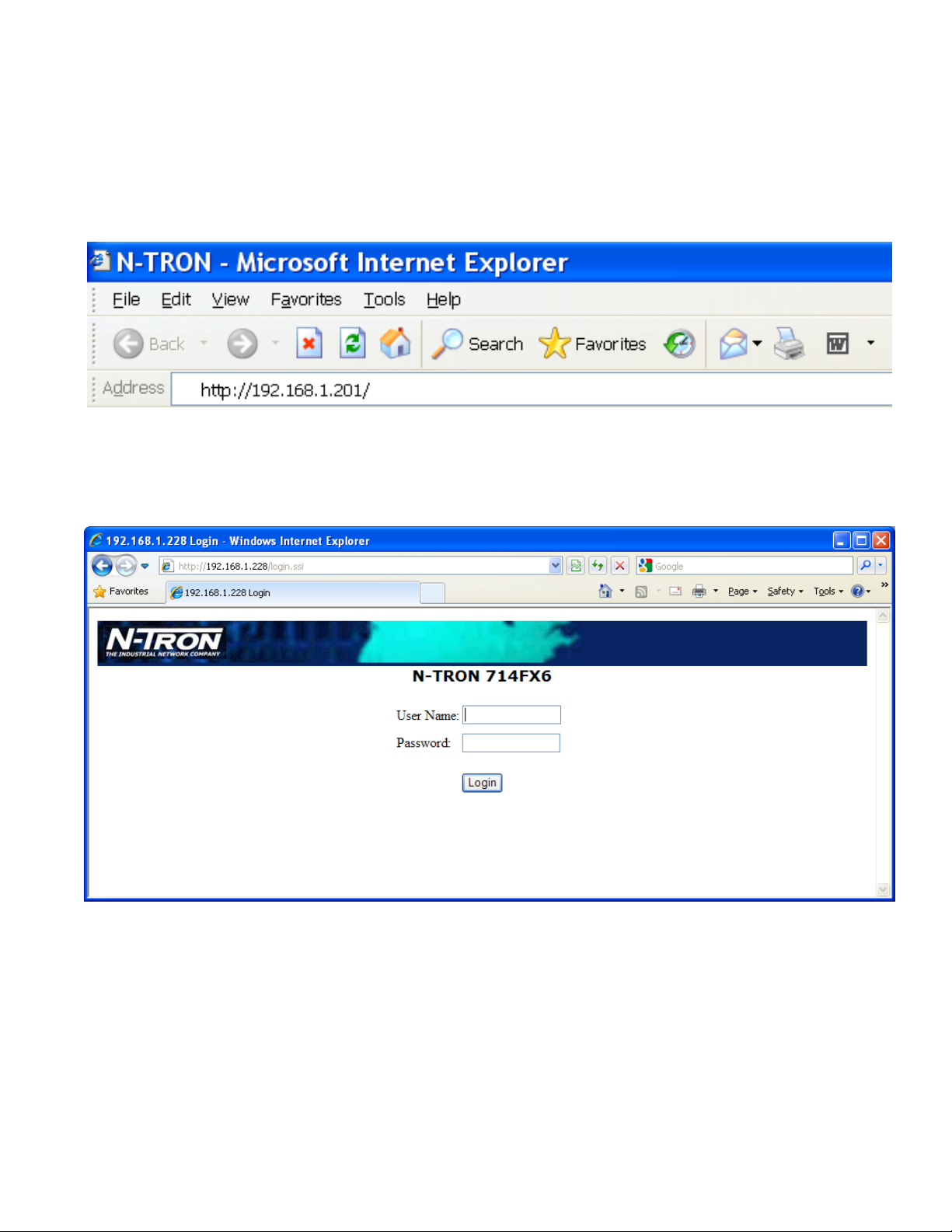
Enter the switch’s IP address in any web browser and login to the web management feature of the 714FX6
Series.
Default:
User Name: admin
Password: admin
(Revised 2015-09-28) Page 25 of 161
Page 26
Web Management - Home
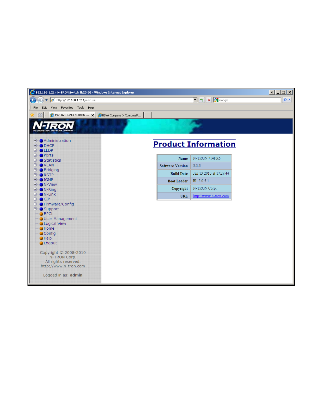
When the administrator first logs onto a 714FX6 Series switch the default home page will be displayed. On
the left hand side of the screen there is a list of configurable settings that the 714FX6 Series switch will
support. This section of the manual will go through each and every choice listed on the left hand side of the
screen and explain how to configure those settings. In the center of the main home page the administrator
can see some basic information like what firmware revision the switch is running. The firmware can be
upgraded at a later time in the field using TFTP.
(Revised 2015-09-28) Page 26 of 161
Page 27
Web Management – Menu Structure
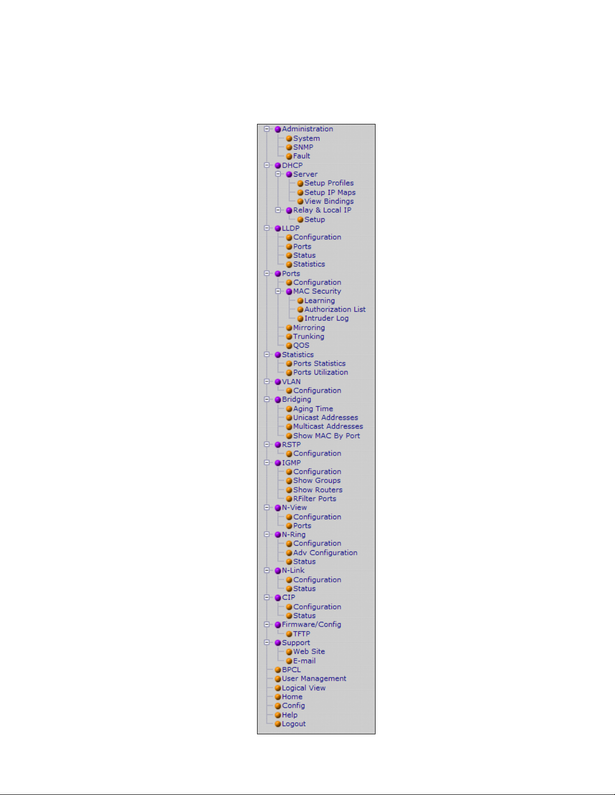
To the left, there is a menu which is shown fully opened below. The pages opened by each of the individual
selections are described in the rest of this section. The use of each of these pages is also described in this
section. In most of the descriptions, only the right side of the page is shown.
(Revised 2015-09-28) Page 27 of 161
Page 28
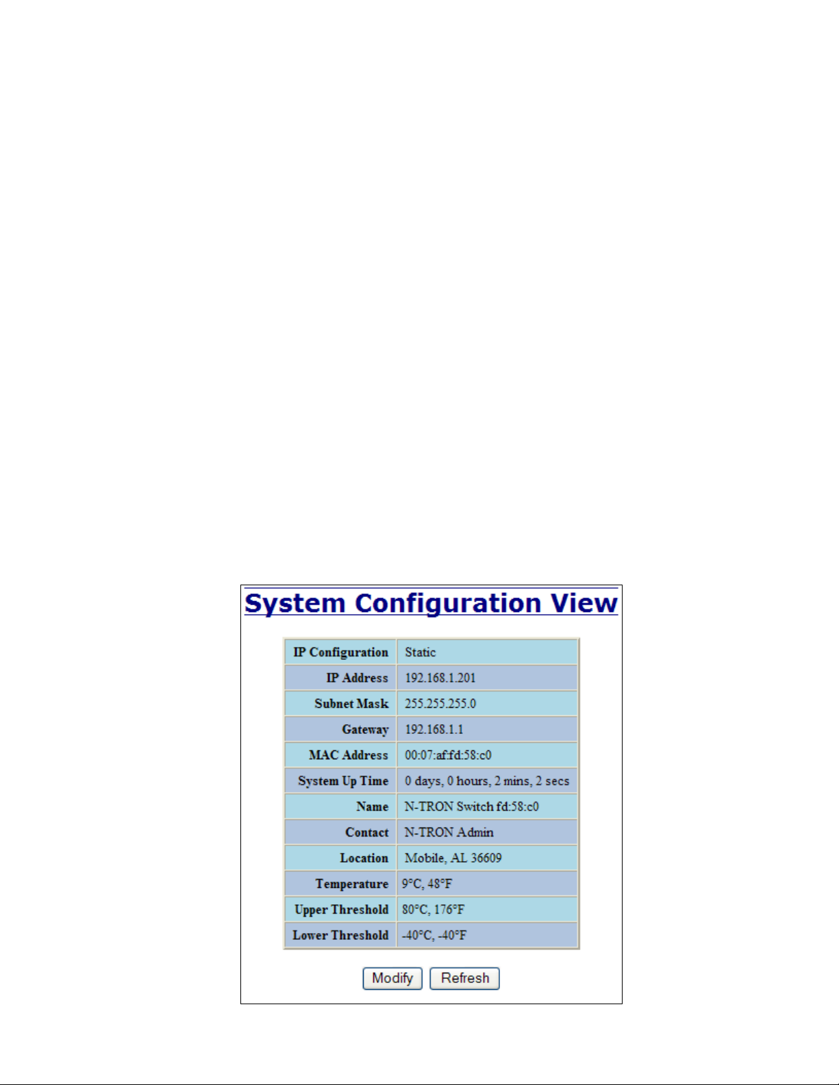
Administration – System
The System tab under the Administration category, lists various information about the switch:
When the IP Configuration is in either DHCP or Static Mode:
IP Configuration
Method used to obtain an IP Address, Subnet Mask and Gateway Address
IP Address
Contains the current IP Address of the device.
Subnet Mask
Contains the current Subnet Mask of the device.
Gateway
Contains the current Default Gateway of the device.
MAC Address
MAC Address of the device.
System Up Time
This parameter represents the total time count. This time has elapsed since the switch was turned ON or RESET.
Name
It shows the name of the product, which allows alphanumeric and special characters (#, _, -) only.
Contact
The person to contact for system issues, which should be someone within your organization.
Location
The physical location of the switch.
Temperature:
The calculated ambient temperature near the switch. This calculation is only valid after a warm-up period.
Upper Threshold:
The highest temperature for the switch without causing a fault to occur. The threshold is specified as an integer in
C degrees. The range is from -60°C to 100°C, and the default is product dependent.
Lower Threshold:
The lowest temperature for the switch without causing a fault to occur. The threshold is specified as an integer in
C degrees. The range is from -60°C to 100°C, and the default is product dependent.
(Revised 2015-09-28) Page 28 of 161
Page 29
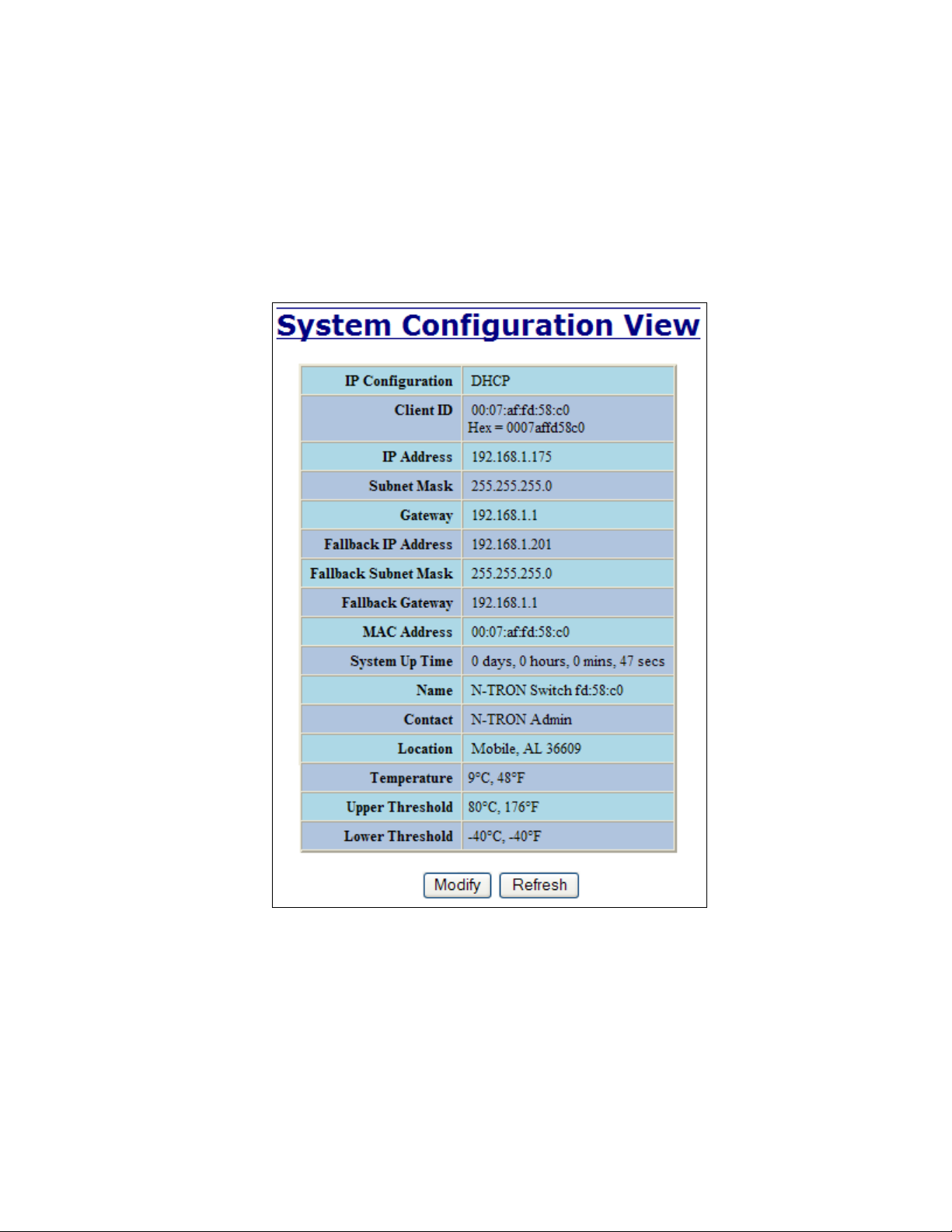
Administration – System, Continued…
When the IP Configuration is in DHCP Mode the following information is added:
Client ID
Option used by DHCP clients to specify their unique identifier. The identifier may be the MAC address,
switch name, or entered as a text string or hex characters.
Fallback IP Address
Contains the configured Fallback IP Address of the device.
Fallback Subnet Mask
Contains the configured Fallback Subnet Mask of the device.
Fallback Gateway
Contains the configured Fallback Gateway of the device.
(Revised 2015-09-28) Page 29 of 161
Page 30
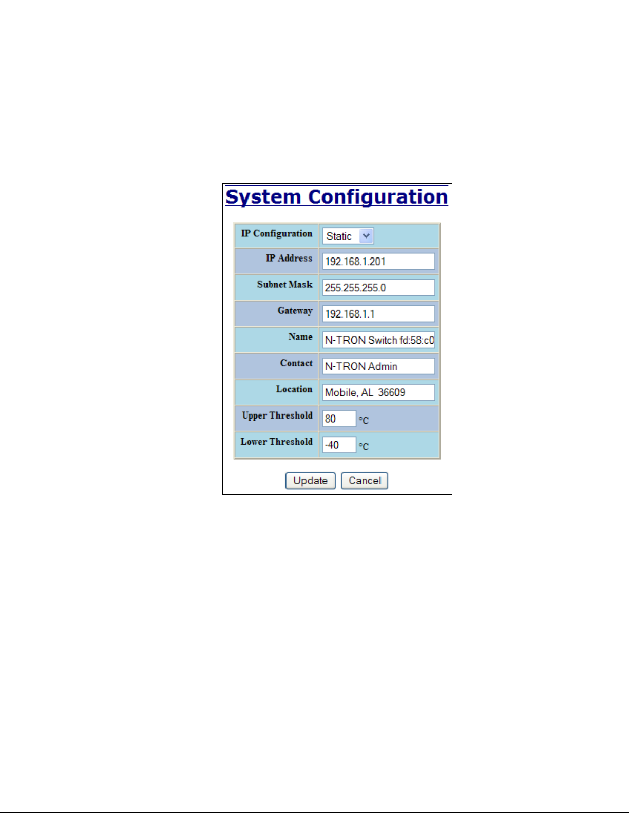
Administration – System, Continued…
By selecting the Modify button, you will be able to change the switch’s IP Configuration, Client ID, IP
Address, Subnet Mask, Gateway, Name, Contact information, and the Location of the switch through the
web management features, depending on the IP Configuration. It is recommended to change the TCP/IP
information through the Command Line Interface (CLI) initially, but it defaults to the following:
IP Configuration – Static
IP Address – 192.168.1.201
Subnet Mask – 255.255.255.0
Gateway – 192.168.1.1
(Revised 2015-09-28) Page 30 of 161
Page 31

Administration – System, Continued…
If the IP Configuration mode is set to DHCP and the Fallback IP address is changed from the default IP
address, then the switch will use the Fallback addresses if the IP configuration isn’t received from a DHCP
server in 2 minutes after initial boot. If Fallback address is used, DHCP Client will stop sending requests. If
the IP Configuration is received from a DHCP server, it will never fallback, even if the lease is lost.
(Revised 2015-09-28) Page 31 of 161
Page 32

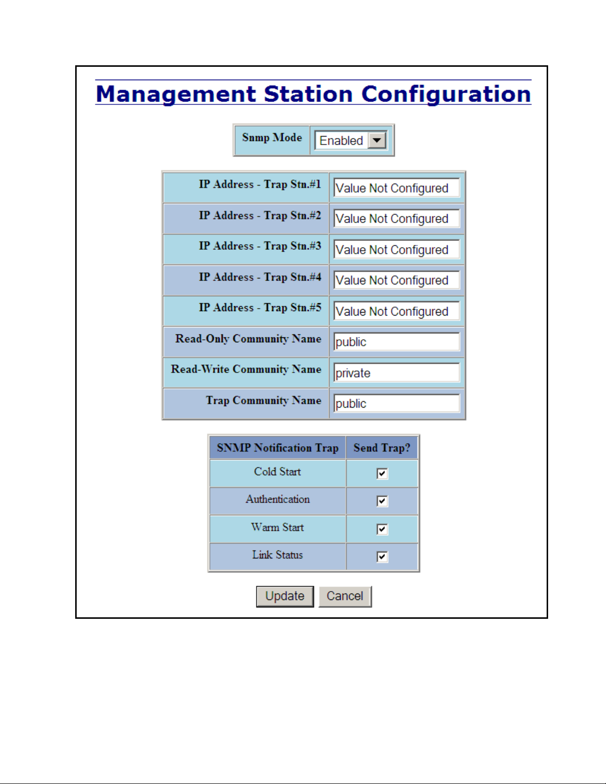
Administration – SNMP
The SNMP tab under the Administration category allows SNMP to be disabled or enabled, and shows a list
of IP Addresses that act as SNMP Traps. The Read-Only, Read-Write, and Trap Community Names are
also shown here.
By selecting the Modify button, you will be able to change any of the fields listed. This allows the user to
set an IP address for a Trap station or change the Community Names. If the SNMP Notification Trap is
enabled, systems that are listed as a Trap station will be sent the corresponding notification trap. To restore
a Trap to “Value Not Configured”, enter ‘0.0.0.0’.
(Revised 2015-09-28) Page 32 of 161
Page 33
Administration – SNMP, Continued…
(Revised 2015-09-28) Page 33 of 161
Page 34

Administration – Fault
The Fault tab under the Administration category provides configurable selections indicating the way to
notify when a Power, N-Ring Manager, N-Link fault, or Port Usage Fault occurs. The notification may
consist of any combination of the options: Show Web, Show LED, and Contact. Power signal faults consist
of V1 and V2. N-Ring Manager signal faults consist of: Broken, Partial Break (Low), Partial Break (High),
and Multiple Managers. N-Link Faults are reported by the N-Link Master and by the N-Link Slave. Port
Usage Fault, if enabled, triggers when actual usage is below the Usage Alarm Low setting, or above the
Usage Alarm High setting (see Port Configuration View and Port Utilization View).
Note: V1 and V2 Power Faults are disabled in factory defaults.
(Revised 2015-09-28) Page 34 of 161
Page 35
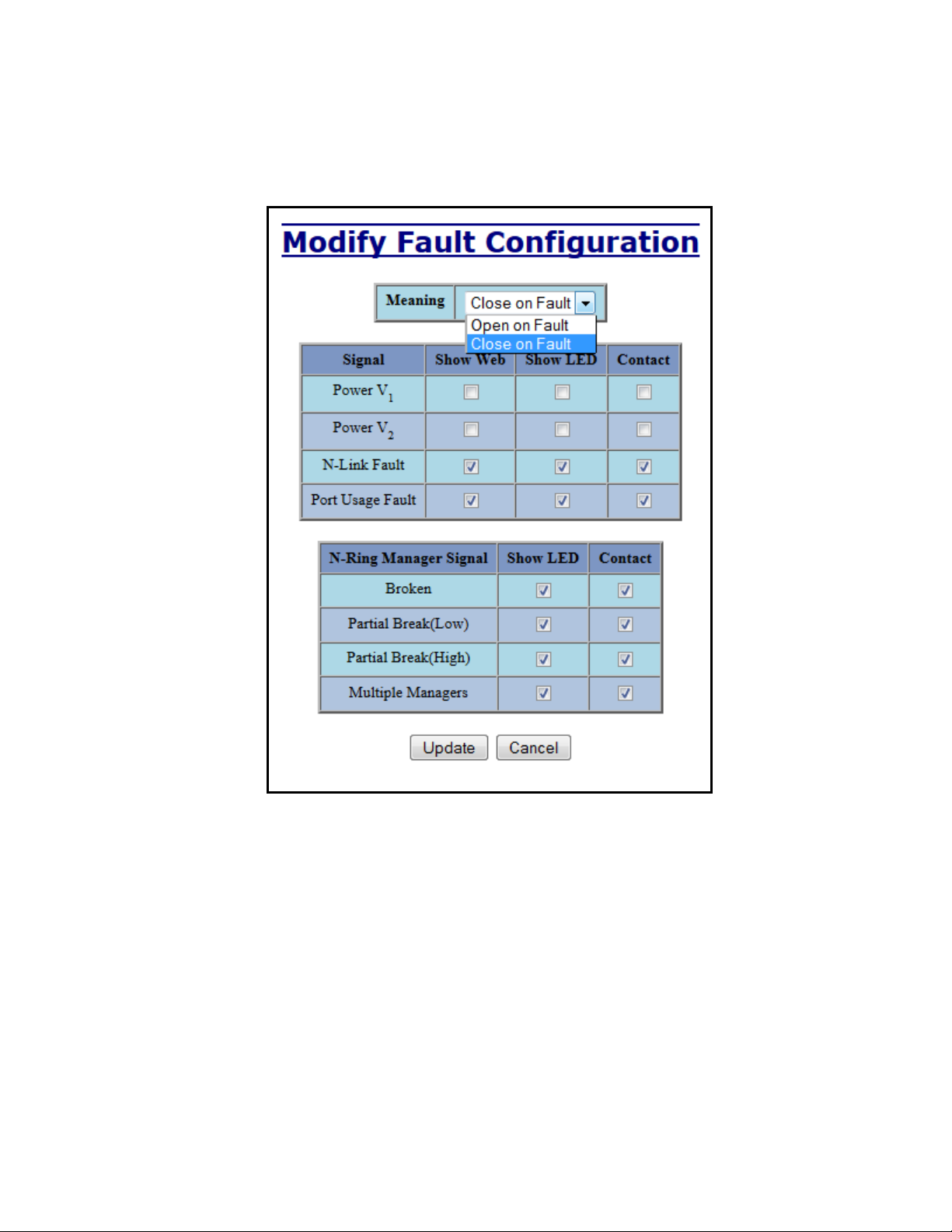
Following the Modify button, the administrator will see a list of configurable fields for the Fault
configuration. The fault relay contacts can be configured to open on fault or to close on fault, with the latter
being the default. Once these fields are filled in to meet the needs of the administrator‘s network, the
changes may be updated by clicking the Update button at the bottom of the page.
(Revised 2015-09-28) Page 35 of 161
Page 36

DHCP – Server – Setup Profiles
The Setup Profiles tab under the DHCP/Server category lists the following information about the current
state of the server and the existing network profiles:
Server Enabled
Indicates whether the DHCP server is active.
Allow Broadcast
Indicates whether the DHCP server will process broadcast messages.
Delay Broadcast (Ms)
The amount of time the DHCP server will delay processing a broadcast message.
Server ID
Descriptive name of the DHCP server.
Profile Name
Descriptive name of the network profile.
Address Pool
Range of IP addresses which the profile can use.
Subnet Address
The most restrictive subnet address calculated from the address pool range.
Subnet Mask
The most restrictive subnet mask calculated from the address pool range.
Domain Name
The domain name to be presented to the client.
Has Profile IP Maps
Indicates whether the profile has IP maps associated with it.
Delete
Deletes the profile along with all IP maps and bindings associated with it. The Default profile cannot be deleted.
(Revised 2015-09-28) Page 36 of 161
Page 37

DHCP – Server – Setup Profiles, Continued…
(Revised 2015-09-28) Page 37 of 161
Page 38

DHCP – Server – Setup IP Maps
The Setup IP Maps tab provides the way to create IP mappings with an existing network profile. There are
three types of mappings that can be created: Dynamic Range, Static Range, and Single IP.
The Dynamic Range type of mapping is used to create a range of dynamic IP addresses for requesting
clients. The following information is required:
Network Profile
An existing network profile to which the IP map applies.
Low IP
The starting IP address of a range.
High IP
The ending IP address of a range.
The Static Range type of mapping is used to create a range of static IP addresses dedicated to specific
ports on a relay agent switch. There are two different data entry formats available according to
whether the relay agent type is for an N-TRON or for a generic switch.
To create a range of static IP addresses on an N-Tron relay agent switch:
Network Profile
An existing network profile to which the IP map applies.
(Revised 2015-09-28) Page 38 of 161
Page 39

DHCP – Server – Setup IP Maps, Continued…
Relay Agent Type
Should be set to N-TRON.
Switch Model
List of N-TRON models that support this feature.
Remote ID
A unique identifier that designates the N-TRON relay agent switch.
Add
Checkbox used to add an IP map for the corresponding port.
Port No
The actual port number.
Port Name
Descriptive name of the port.
VLAN
VLAN ID that the port is a member of.
Circuit ID
Auto-generated string based on the port name and VLAN ID.
IP Address
IP address to assign to the IP map.
(Revised 2015-09-28) Page 39 of 161
Page 40

DHCP – Server – Setup IP Maps, Continued…
(Revised 2015-09-28) Page 40 of 161
Page 41

DHCP – Server – Setup IP Maps, Continued…
To create a range of static IP addresses on a generic relay agent switch:
Network Profile
An existing network profile to which the IP map applies.
Relay Agent Type
Should be set to Generic.
Port Count
The number of ports on the particular relay agent switch.
Add
Checkbox used to add an IP map for the corresponding port.
Port No
The actual port number.
Remote ID
The identifier that corresponds to an Option 82 Remote ID sub-option used by the particular relay agent switch.
Circuit ID
The identifier that corresponds to an Option 82 Circuit ID sub-option used by the particular relay agent switch.
IP Address
IP address to assign to the IP map.
(Revised 2015-09-28) Page 41 of 161
Page 42
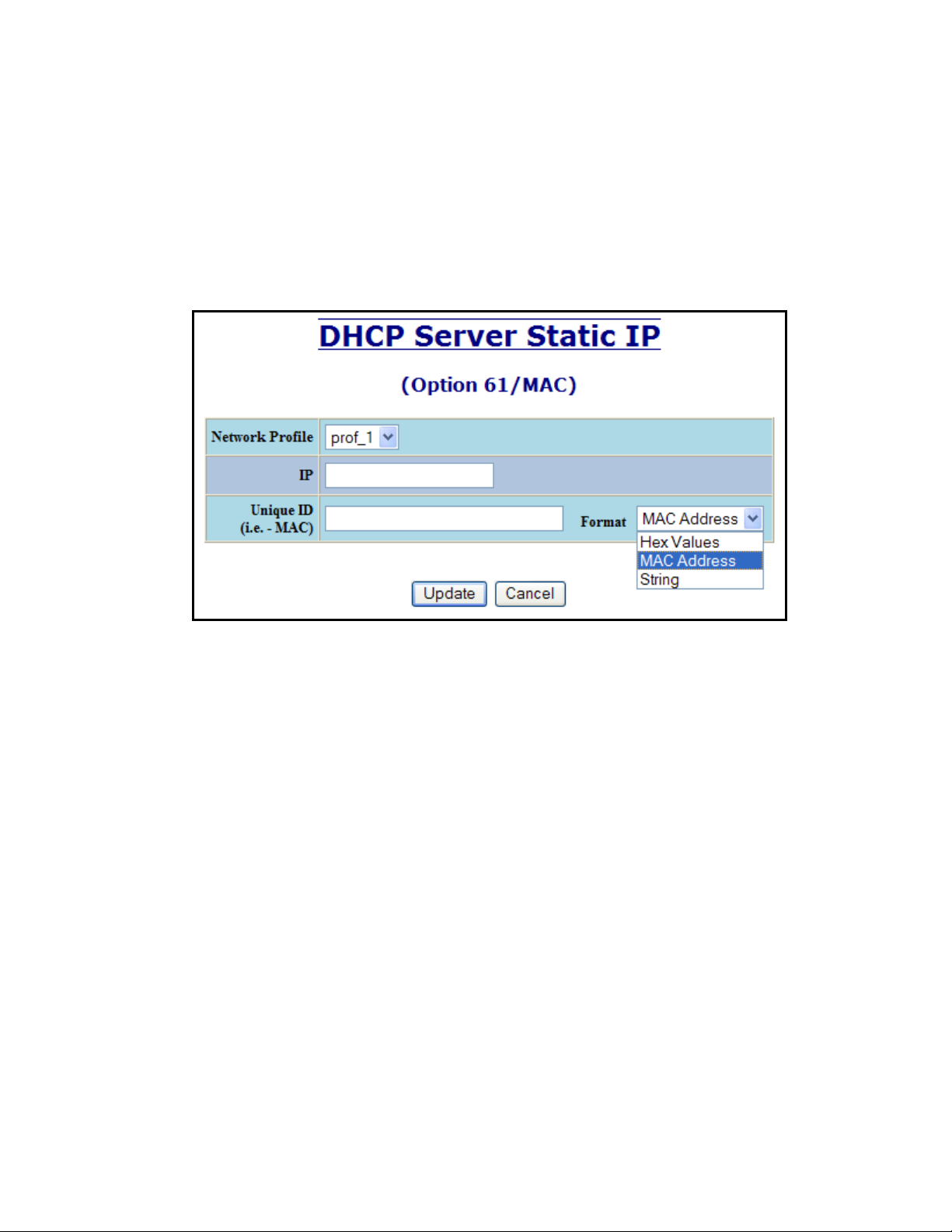
DHCP – Server – Setup IP Maps, Continued…
The Single IP type of mapping is used to create a static IP address for an individual client. The following
information is required:
Network Profile
An existing network profile to which the IP map applies.
IP
The static IP address to offer to a client.
Unique ID
The unique identifier that must match either the client identifier (Option 61) or the client’s hardware address (MAC).
Format
Designates how the Unique ID is interpreted.
(Revised 2015-09-28) Page 42 of 161
Page 43

DHCP – Server – View Bindings
The View Bindings tab lists the bindings of physical devices to IP addresses that are in use or offered:
Network Profile
The profile applied to the binding entry.
Binding Identifier
The client associated with the binding entry.
Client Hardware Address (MAC)
The client’s MAC address.
Client IP Address
The actual IP address assigned to the binding entry.
Status
Indicates the current status of the binding entry.
Release
Removes the corresponding binding.
WARNING: By releasing an IP address, it is possible to end up with two physical devices with the same IP address
which may cause network disruption to that IP address.
(Revised 2015-09-28) Page 43 of 161
Page 44

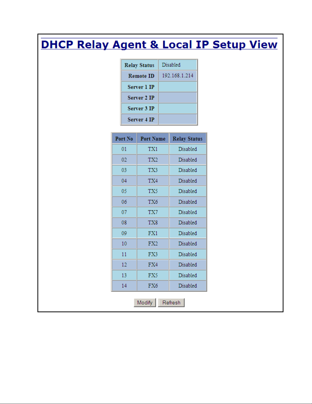
DHCP – Relay & Local IP - Setup
The Setup tab under the DHCP/Relay & Local IP category shows the current state of the relay agent.
By selecting the Modify button, you can configure general settings of the relay agent, as well as, configure
settings on a per port basis. The following describes these settings:
(Revised 2015-09-28) Page 44 of 161
Page 45

DHCP – Relay & Local IP – Setup, Continued…
Disabled
The port will function without relay agent processing.
Enabled
The port will relay DHCP client-originated broadcast packets to the DHCP servers.
Assign Local IP
The port will not relay DHCP client-originated broadcast packets. Instead the relay agent
will offer the port’s locally assigned IP address to the client.
Relay Status
Indicates whether the DHCP relay agent is active.
Remote ID
The unique identifier that designates the relay agent switch.
Server # IP
The configured IP address of the DHCP servers.
Port No
The actual port number.
Port Name
The descriptive name of the port.
Relay Status
The selection to designate whether the port will perform relay agent functionality. The choices are:
Other Data
When the Relay Status is set to Enabled, the Circuit ID for the port can be specified. When the Relay Status is set to
Assign Local IP, the IP address for the port can be specified.
(Revised 2015-09-28) Page 45 of 161
Page 46
DHCP – Relay & Local IP – Setup, Continued…
(Revised 2015-09-28) Page 46 of 161
Page 47
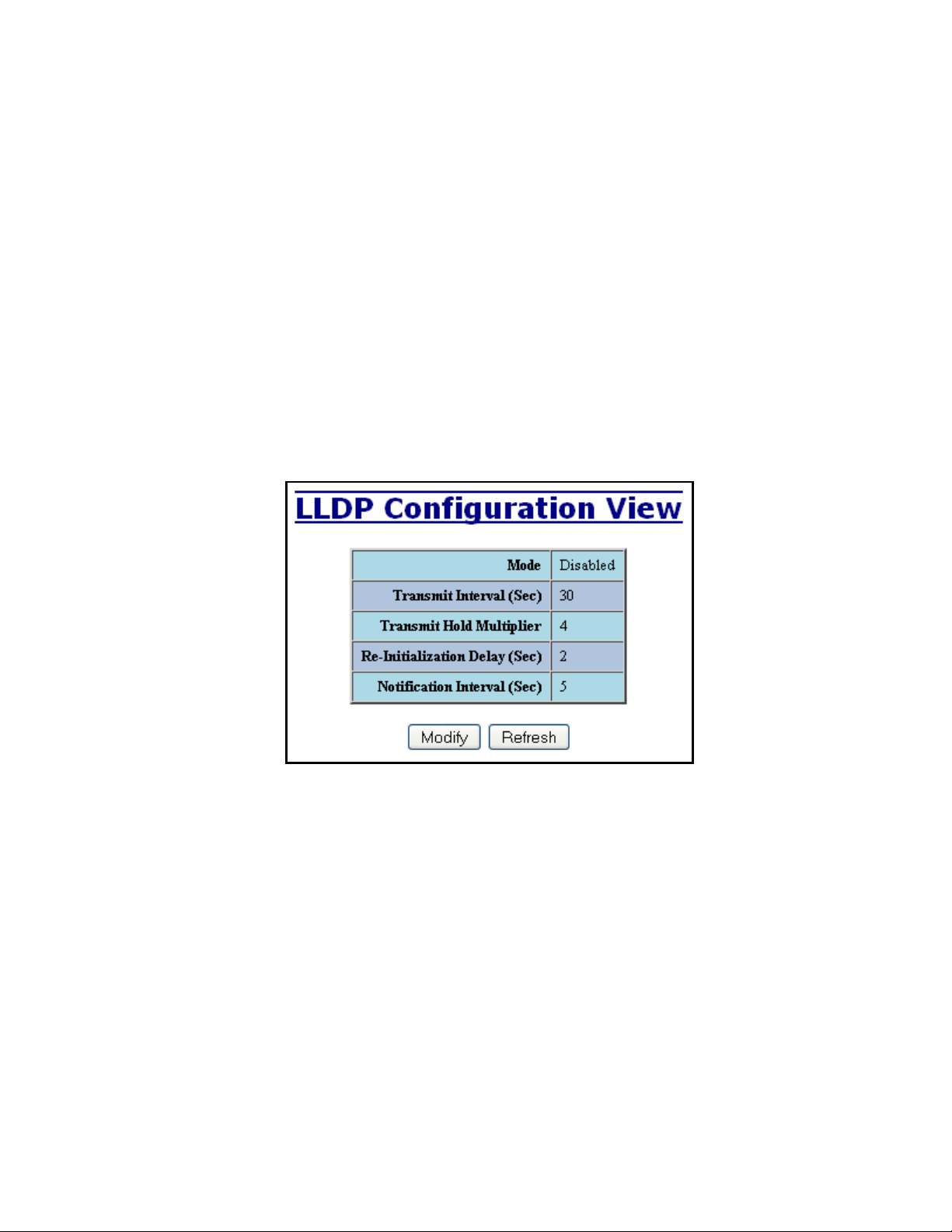
LLDP - Configuration
Mode:
Enables or Disables LLDP on the Switch. Default: Disabled
Transmit Interval:
Specifies the interval at which LLDP frames are transmitted. Default = 30 seconds.
Transmit Hold Multiplier:
Specifies a multiplier on the Transmit Interval when calculating a Time-to-Live value. Default = 4.
Re-Initialization Delay:
Specifies a minimum time an LLDP port will wait before re-initializing after setting the port to disable followed by
setting a port to Tx-Only or Tx/Rx. This prevents excessive Notifications if someone toggles between Disabled and
Enabled on LLDP Port settings. Default = 2 Seconds.
Notification Interval
Specifies the interval between successive Notifications generated by the switch. If a port sends out a notification and
another port tries to send out a notification, the notification will not be sent until the interval expires.
Default = 5 Seconds.
Note: A redundant network topology will have one or more blocking ports to prevent looping and
broadcast storms. LLDP will not receive neighbor information into a blocked port, though the
LLDP information will be transmitted out of a blocked port. Therefore, the switch that has the
blocked port will not know about the neighbor on the other side of the blocked port, but the neighbor
will know about the switch that has the blocked port.
(Revised 2015-09-28) Page 47 of 161
Page 48

LLDP - Ports
LLDP Ports View
Port Name
Descriptive name of the port on the local switch.
Transmit
Enables or Disables LLDP Transmission on the switch.
Receive
Enables or Disables Receiving of LLDP Frames from neighbor switches.
Allow Management Data
Allow the Transmission of Management type information. For example: IP Address of switch, Port Description, System
Name and Vlan information.
Allow Notifications
Notifications are transmitted when local or remote data changes.
(Revised 2015-09-28) Page 48 of 161
Page 49
LLDP - Status
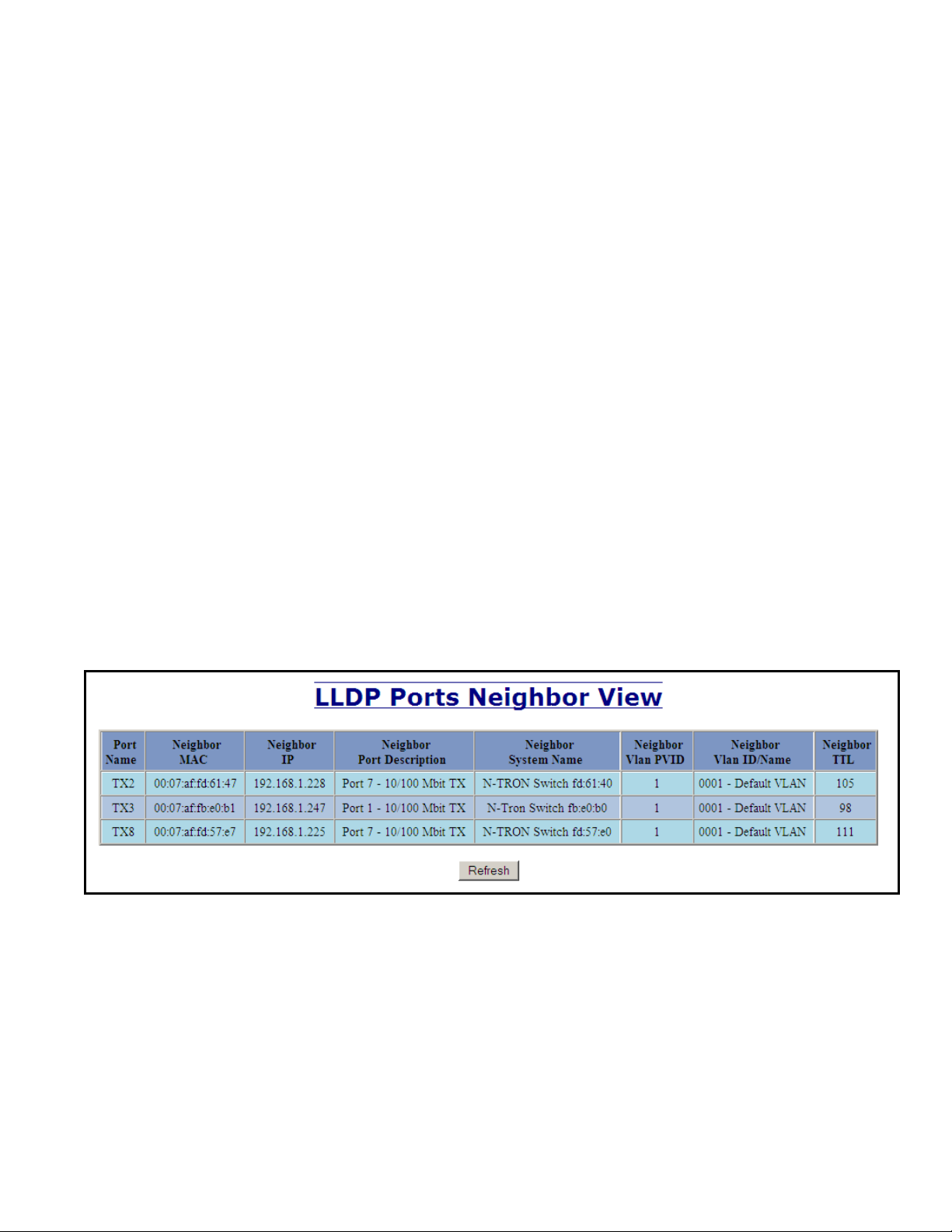
LLDP Ports Neighbor View
The Status View shows the results of LLDP discovery. The LLDP Ethernet frames received from neighboring ports are
composed of a collection of data units called TLVs. Each TLV contains a defined type of information such as the Chassis ID
described below, which contains the MAC address of the device sending the frame. The maximum number of neighbors displayed
per port is four.
Port Name
The name of the local port on which the neighbor information was received.
Neighbor MAC
MAC address of neighbor switch. Corresponds to the LLDP Chassis ID TLV.
Neighbor IP
IP address of neighbor switch. Corresponds to the LLDP Management Address TLV.
Neighbor Port Description
Description of the neighbor Port from which the LLDP frame was sent.
Neighbor System Name
The system's administratively assigned name on the neighbor switch.
Neighbor VLAN PVID
The Port VLAN identifier (PVID) associated with the neighbor port.
Neighbor VLAN ID/Name
A list of all VLAN's for which the neighbor port is a member.
Neighbor TTL
Indicates the number of seconds that the information associated with this neighbor will be valid. Time to Live (TTL)
(Revised 2015-09-28) Page 49 of 161
Page 50

LLDP - Statistics
LLDP Local Port Statistics View
Port Name
Descriptive name of the port on the local switch.
Transmitted Frames
The total number of LLDP Frames sent out from the local switch.
Received Frames
Total number of LLDP frames received by the local switch.
Discarded Frames
The total number of frames discarded due to incorrect TLV's in frame.
Error Frames
Total count of all LLDP frames received with one or more detectable errors.
Neighbor Age Outs
Total count of the times that a neighbor's information has been deleted from the switch because the
Time to Live (TTL) has expired.
LLDP Port Status
Local Port setting (Receive-Rx/Transmit-Tx/Disable).
(Revised 2015-09-28) Page 50 of 161
Page 51

Ports – Configuration
The Configuration tab under the Ports category will show a detailed overview of all the active ports on the
switch. The overview will display the following information:
Port Number
This is the port index.
Port Name
This field displays the name of the port. The designation of TX is for copper ports, and FX is for fiber optic ports.
Admin Status
This configurable field displays the existing status of the port whether it is Enabled/Disabled.
Link Status
Current Link state of the port.
Auto Negotiation State
This configurable field displays the current auto-negotiation state whether it is Enabled/Disable.
Port Speed
This configurable field displays the speed of each port 10/100/1000 Mbps.
Duplex Mode
This configurable field displays the existing mode of the port whether it is Full Duplex/Half Duplex.
Flow Control State
This configurable field displays the existing flow control status of each port. When enabled, the individual port supports
half-duplex back pressure and full-duplex flow control. The default is Disabled.
Force High Priority State
This configurable field displays the port priority status of each port. When enabled for a port all frames received on that
port will be forced to the highest priority queue regardless of 'Default Priority' setting or priority tags within the received
frames. The default is Disabled. In an untagged N-Ring configuration, the N-Ring ports on the N-Ring Manager and
active N-Ring Members will be Enabled.
Default Priority
This configurable field displays the default QoS priority for the port when an untagged frame is received. The range is
0-7.
RSTP State
The current RSTP status of a port. It may contain Disable/Discarding/Learning/Forwarding.
PVID
This configurable field displays the existing port VLAN ID setting. The allowable range is 1-4094.
Usage Alarm Low (%)
The bandwidth utilization percentage below which a fault will be triggered if enabled. For half duplex the bandwidth
utilization percentage is the sum of both RX and TX bandwidth utilization, and for full duplex this is the higher of TX or
RX bandwidth utilization. See Port Utilization View and Port Usage Fault on Fault Configuration View.
Usage Alarm High (%)
The bandwidth utilization percentage above which a fault will be triggered if enabled. For half duplex the bandwidth
utilization percentage is the sum of both RX and TX bandwidth utilization, and for full duplex this is the higher of TX or
RX bandwidth utilization. See Port Utilization View and Port Usage Fault on Fault Configuration View.
(Revised 2015-09-28) Page 51 of 161
Page 52
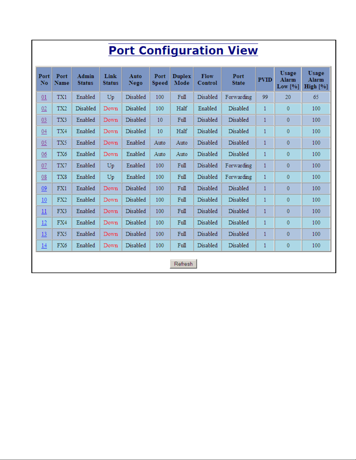
Ports – Configuration, Continued…
(Revised 2015-09-28) Page 52 of 161
Page 53

Ports – Configuration, Continued…
The User can click on the Port Number to configure each port individually. This will allow the user to
change the port’s settings for the following fields which are explained above:
Admin Status
Speed and Duplex
Flow Control
Force High Priority
Default Priority
PVID
Usage Alarm Low
Usage Alarm High
(Revised 2015-09-28) Page 53 of 161
Page 54

Ports – MAC Security – Learning
The Learning tab allows the administrator to control the learning or locking modes for the ports. ‘Locked’
is the secure mode. ‘Learning’ builds an internal list of authorized MAC addresses based on an approved
LAN. When the current mode is ‘Learning’, no ports are secured.
(Revised 2015-09-28) Page 54 of 161
Page 55

Ports – MAC Security – Learning, Continued…
In ‘Locked’ mode, ‘Secured Ports’ shows the ports that are presently secured. Note: when N-Ring and/or
N-Link are used, the N-Ring/N-Link ports will not have MAC Security enabled.
(Revised 2015-09-28) Page 55 of 161
Page 56

Ports – MAC Security – Learning, Continued…
The Modify button allows the administrator to change the current mode. When transitioning from
‘Learning’ to ‘Locked’, the Address Resolution Logic (ARL) table represents the authorized MAC
addresses, with the addition of any manually entered addresses (refer to Authorization List section below).
Transitioning from ‘Locked’ to ‘Learning’, clears the ARL for all ports.
(Revised 2015-09-28) Page 56 of 161
Page 57

Ports – MAC Security – Authorization List
The Authorization List tab allows for manual entry or deletion of authorized MAC source addresses with
associated authorized ports.
Selecting Modify displays the MAC Authorization Configuration page, which allows the administrator to
add new entries, delete existing entries, or edit authorized ports of existing entries.
Selecting Delete removes the associated entry. Selecting Add displays the MAC Authorization Entry page,
showing default values for the administrator to modify (see below). When an entry number hyperlink is
selected, this same page is displayed except it shows the associated MAC address and authorized ports.
(Revised 2015-09-28) Page 57 of 161
Page 58

Ports – MAC Security – Intruder Log
The Intruder Log tab displays a list of unauthorized MAC addresses that attempted to access the secured
device. Each intruder entry in the log is unique, and is based on the combination of MAC address, VLAN,
and port. Only the first occurrence of the intruder is listed. The log is ordered by most recent first, based on
the system time. The maximum number of entries is 100. If more than 100 intruders are detected, the
oldest entries are deleted. The log is not saved through a power cycle.
An entry can be individually removed from the log by selecting the associated Delete button. All entries or
entries specific to a port can also be removed from the log by choosing the option in the dropdown list and
then selecting the Clear button.
(Revised 2015-09-28) Page 58 of 161
Page 59

Ports – Mirroring
A mirroring port is a dedicated port that is configured to receive the copies of Ethernet frames that are being
transmitted out and also being received in from any other port that is being monitored.
The Mirroring tab under the Ports category displays the status including the list of Source Ports and the
Destination Port that the Sources are being mirrored to.
(Revised 2015-09-28) Page 59 of 161
Page 60
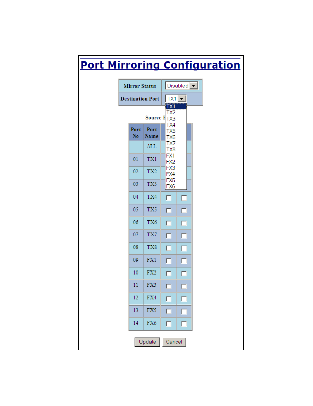
Ports – Mirroring, Continued…
Following the Modify button, you can enable the status of port mirroring and select source ports and the
destination port that the source ports will be mirrored to.
(Revised 2015-09-28) Page 60 of 161
Page 61
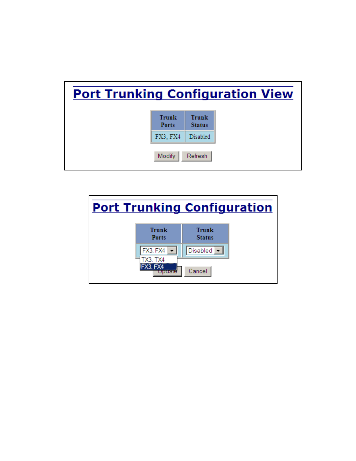
Ports – Trunking
The Trunking tab under the Ports category displays the following details:
Trunk Ports
This field displays the ports associated with the trunk.
Trunk Status
This configurable field displays the existing status of the trunk. It can be either Enabled/Disabled.
By selecting the Modify button, you can select a trunk group.
Note: RSTP must be disabled in order to use the Trunking feature.
Two ports of the same speed can constitute a valid trunk.
Only 1 Trunk per switch can be created.
All trunk ports must be at the same speed and duplex mode. If a port is not linked, there could be
difficulty as to similar speed and duplex mode. It is best to hard code speed and duplex mode for
each trunking link, at both ends.
Do not use Trunking on an N-Ring manager. Do not connect the N-Ring to actively Trunking ports
on an Auto Member.
(Revised 2015-09-28) Page 61 of 161
Page 62

Ports – QOS
The QOS decision tree chooses the highest priority Transmit Queue (TQ) of the following criteria:
Force High Priority (Port Based) TQ mapping, IEEE 8021.p TQ mapping, or DSCP TQ mapping.
The QOS tab under the Ports category displays the following details:
Port Number
This is the port index.
Port Name
This field displays the name of the port.
Include DSCP
This field displays the status of whether or not to include the RFC 2474 DSCP TOS (Type of Service) in the TQ
decision. When enabled, the DSCP TOS is included when evaluating traffic priority.
Include 802.1p
This field displays the status of whether or not to include the IEEE 802.1p COS (Class of Service) in the TQ decision.
When enabled, the IEEE 802.1p COS is included when evaluating traffic priority.
Force High Priority
This field displays the Force High Priority status. When enabled, the port based priority is included in the TQ decision
for all ports and all frames received on a port will use the default QOS priority for that port in the TQ decision.
Port Priority
This field displays the default QOS priority for that port. This is the IEEE 802.1p COS (Class of Service) assigned to all
untagged ingress frames, or all ingress frames if Force High Priority is enabled. The range is 0-7.
(Revised 2015-09-28) Page 62 of 161
Page 63

Ports – QOS, Continued…
Following the Modify button, the administrator can independently configure the ports for different QOS
functionality. Once these fields are filled in to meet the needs of the administrator’s network, the changes
may be updated by clicking the Update button at the bottom of the page.
(Revised 2015-09-28) Page 63 of 161
Page 64

Statistics – Port Statistics
The Ports Statistics tab under the Statistics category displays a list of MIB parameters. Each port has a
separate counter for each parameter. This gives users the ability to see what kind of packets are going over
which ports. At the bottom of the page for each port there are two buttons. Refresh will update the statistics
for that port number and Clear will reset all the counters for that port number.
(Revised 2015-09-28) Page 64 of 161
Page 65

Statistics – Port Utilization
The Ports Utilization tab under the Statistics category shows all the ports on the switch and will display a
bar graph showing the percentage of bandwidth being used. These figures and bars are for a general feeling
of what the bandwidth usage is. N-Tron recommends the use of N-View in order to get a more precise
bandwidth usage figure.
The scale can be adjusted for the task at hand:
(Revised 2015-09-28) Page 65 of 161
Page 66

VLAN – Configuration
Note: Consult the Table of Contents for ‘VLAN Addition and Deletion Example’, and ‘VLAN
Configuration Examples’. These are detailed examples.
Replace VID Tag with Default Port VID
Specifies whether or not to replace the incoming VID tag with the port's designated VID.
Perform Ingress Filtering
Specifies whether or not to filter out ingress frames when a VID violation is detected.
Discard Non-Tagged for Ports
Specifies whether or not non-tagged ingress frames are dropped by the selected ports.
Note that for convenience in most frequent use:
Ports are deleted from group1 as each port is added to another group.
Ports are added to group1 if a deletion leaves a port with no group.
If it is desired to have a port on group1 and also on other group(s) configure group1 last to achieve that.
Note: RSTP on overlapping VLANs is not supported and the system will automatically disable RSTP on all
but the lowest VID VLANs that have overlapping ports.
(Revised 2015-09-28) Page 66 of 161
Page 67

VLAN – Group Configuration
VLAN ID
This field displays the VLAN ID. The range should be 1-4094.
VLAN Name
This configurable field displays the name of the VLAN, which accepts alphanumeric and special characters (#, _, -, .)
only.
Allow Management
Specifies whether or not all ports in this VLAN are management ports.
Change PVID of Member Ports
Specifies whether or not the PVID of the member ports is set to this VLAN ID.
Port No
This is the port index.
Port Name
Descriptive name of the port
Group Member
Specifies whether or not the port is included in the group.
Untag on Egress
Specifies whether or not egress frames are tagged by the designated port.
(Revised 2015-09-28) Page 67 of 161
Page 68
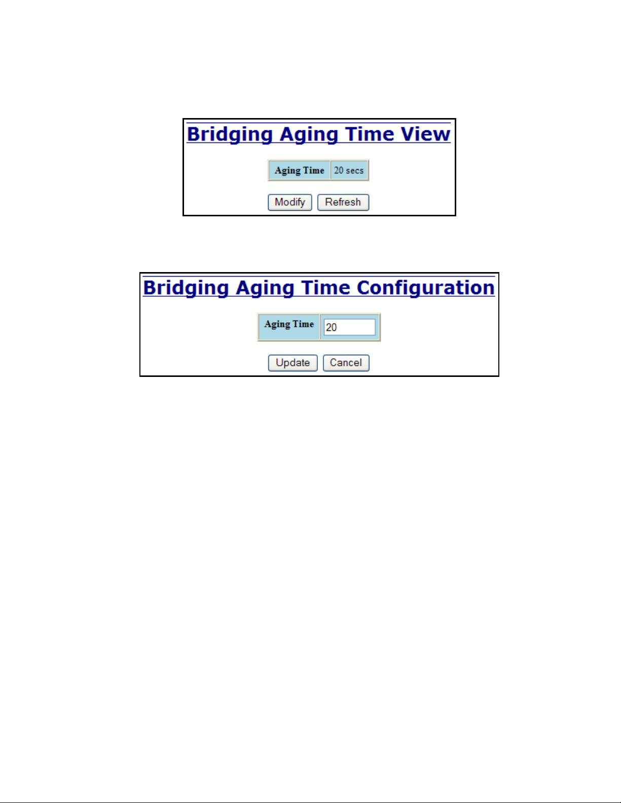
Bridging – Aging Time
The Aging Time tab under the Bridging category will display the currently configured Aging Time. This
page allows users to modify this variable to meet their needs.
After selecting the Modify button, the user will be presented with a page that allows the number to be
entered and updated. The default aging time is 20 seconds.
Note: If the switch is an active participant of an N-Ring, then the N-Ring Aging Time will be used instead
of the Bridging Aging Time.
(Revised 2015-09-28) Page 68 of 161
Page 69

Bridging – Unicast Addresses
The Unicast Addresses tab under the Bridging category will display a list of MAC addresses that are
associated with each respective port number. This can be used to statically assign a MAC address access to
a single port on the switch.
Following the Add button on the page above, the administrator must enter a valid MAC address and
associate it with a port number on the switch. Once the administrator hits the Add button, the changes will
take effect instantly.
(Revised 2015-09-28) Page 69 of 161
Page 70

Bridging – Unicast Addresses, Continued…
Once a static MAC address has been added, it will be displayed in a list on the main page under Unicast
MACs tab.
Following the Remove button on the example above, an administrator can select a static MAC address from
the list using a pull-down menu. After selecting the MAC address, the administrator needs to press the
Remove button on the page to remove the entry
(Revised 2015-09-28) Page 70 of 161
Page 71

Bridging – Multicast Addresses
The Multicast Addresses tab under the Bridging category will display a list of Multicast Group Addresses
that are associated with respective port numbers. This may be used to statically assign a Multicast Group
Address access to a group of ports on the switch.
Following the Add button on the page above, the administrator must enter a valid Multicast Group Address
and associate it with a port number or list on the switch. Once the administrator clicks on the Add button,
the changes will take effect instantly.
Note: If there are multiple ports on different VLANs, the 714FX6 will apply the static multicast address to
the lowest VLAN-ID that is associated with one of the ports assigned to the static multicast address.
So if the lowest VLAN-ID contains all the ports assigned to the static multicast address (an umbrella
VLAN), it will function for all those ports with no problems. This can be achieved with overlapping
VLANs.
(Revised 2015-09-28) Page 71 of 161
Page 72

Bridging – Multicast Addresses Continued…
After adding a Multicast Group Address, it will appear on the main list and will show the associated ports
that go along with that address.
Following the Remove button on the example above, the administrator will be presented with a list of
Multicast Group Addresses that are configured on the switch. Using the pull-down menu, the administrator
should select the desired address to be removed. Then click on the Remove button at the bottom of the
page.
Note: If there are multiple ports on different VLANs, the 714FX6 will apply the static multicast address to
the lowest VLAN-ID that is associated with one of the ports assigned to the static multicast address.
So if the lowest VLAN-ID contains all the ports assigned to the static multicast address (an umbrella
VLAN), it will function for all those ports with no problems. This can be achieved with overlapping
VLANs.
(Revised 2015-09-28) Page 72 of 161
Page 73

Bridging – Show MAC by Port
This feature shows the MAC addresses of devices connected to each switch port and the IP Addresses
associated with the MACs. The browser page ‘View MAC by Port’ shows the MAC for the device found
on each port, and the IP for the MAC presented if available. If more than one device is on that port, then the
lowest alphanumeric of those MAC addresses is shown and underlined.
The ‘Active IP Probe’ field is configurable using the ‘Modify’ button, and also displays the existing
Enabled or Disabled status of this feature. The default is disabled. When disabled the switch generates no
ethernet traffic for this purpose, but can still present some information gathered passively.
(Revised 2015-09-28) Page 73 of 161
Page 74
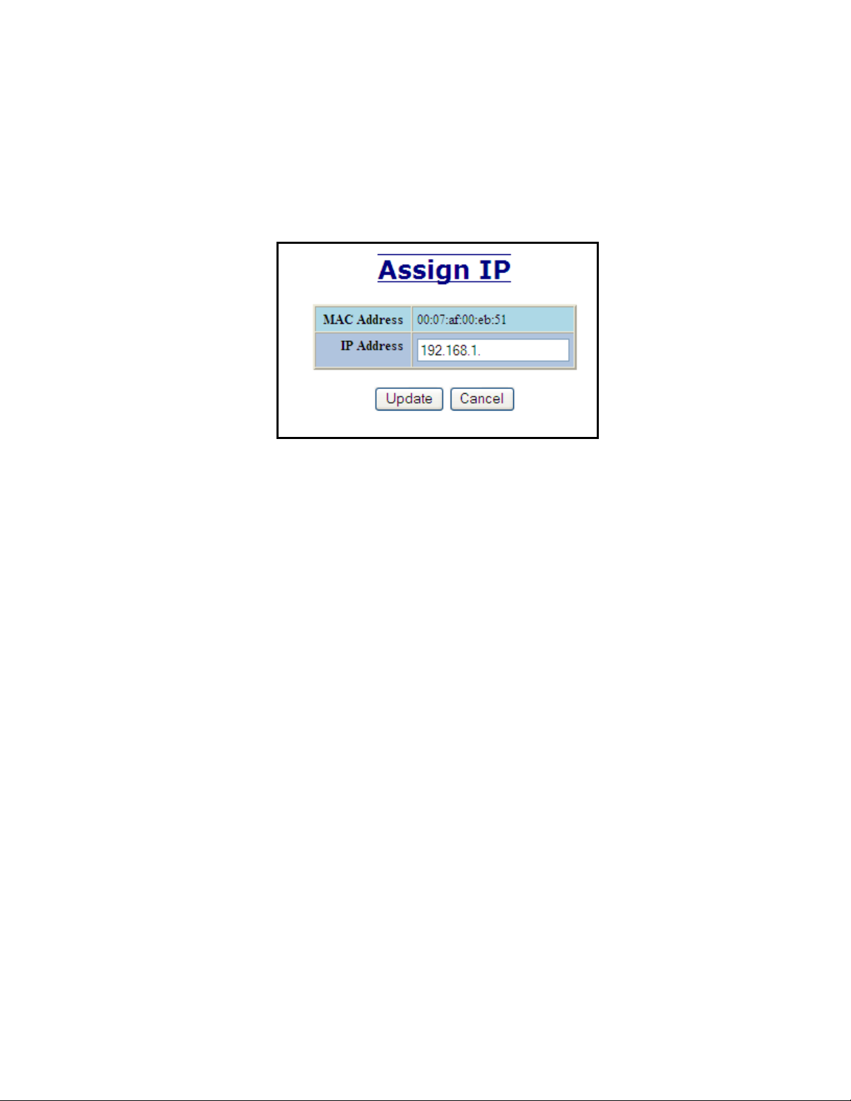
The ‘IP’ field shows an Auto-detected or manually entered IP address. If there is a MAC address for the port
and an IP address was not discovered there is an ‘Assign IP’ button to allow the user to enter an IP address.
If ‘Active IP Probe’ is enabled, manually entered IP values are underlined and validated. A validated IP for
that MAC is presented in green and if validation fails the IP will be red and underlined. Note that some
devices do not have an IP Address, and that some devices that do have an IP Address may not respond to the
methods used to detect their IP Address.
Invoking the ‘Assign IP’ button on the example above, the administrator will be presented with a form in
which to enter a manually assigned IP, as below:
When an IP has been manually entered a button is provided to ‘Delete IP’, and invoking it will allow the
administrator to delete the manual association of an IP to that MAC.
(Revised 2015-09-28) Page 74 of 161
Page 75

RSTP – Configuration
The Configuration tab under the RSTP category will display the RSTP information for the first VLAN.
Using the pull-down menu at the top of the page an administrator can choose which VLAN to configure
RSTP on. Once the VLAN is selected, the administrator may configure the bridge by clicking on the
‘Configuration’ link in the middle of the page.
(Revised 2015-09-28) Page 75 of 161
Page 76

RSTP – Configuration Continued…
The configuration screen for the VLAN that was previously selected will look like the example below. Here
the administrator can make changes such as the Hello Time, Forward Delay, Max Age, Priority, and the
Status of RSTP on that VLAN. The administrator or user can see the current RSTP status of the ports on
that VLAN by clicking on the ‘here’ link to view RSTP Port Configuration at VLAN#.
Note: It is recommended that RSTP rings consist of RSTP capable switches.
Trunking must be disabled in order to use RSTP.
Do not create redundant links unless either RSTP or N-Ring is enabled.
RSTP on overlapping VLANs is not supported and the system will automatically disable RSTP on all
but the lowest VID VLANs that have overlapping ports.
(Revised 2015-09-28) Page 76 of 161
Page 77
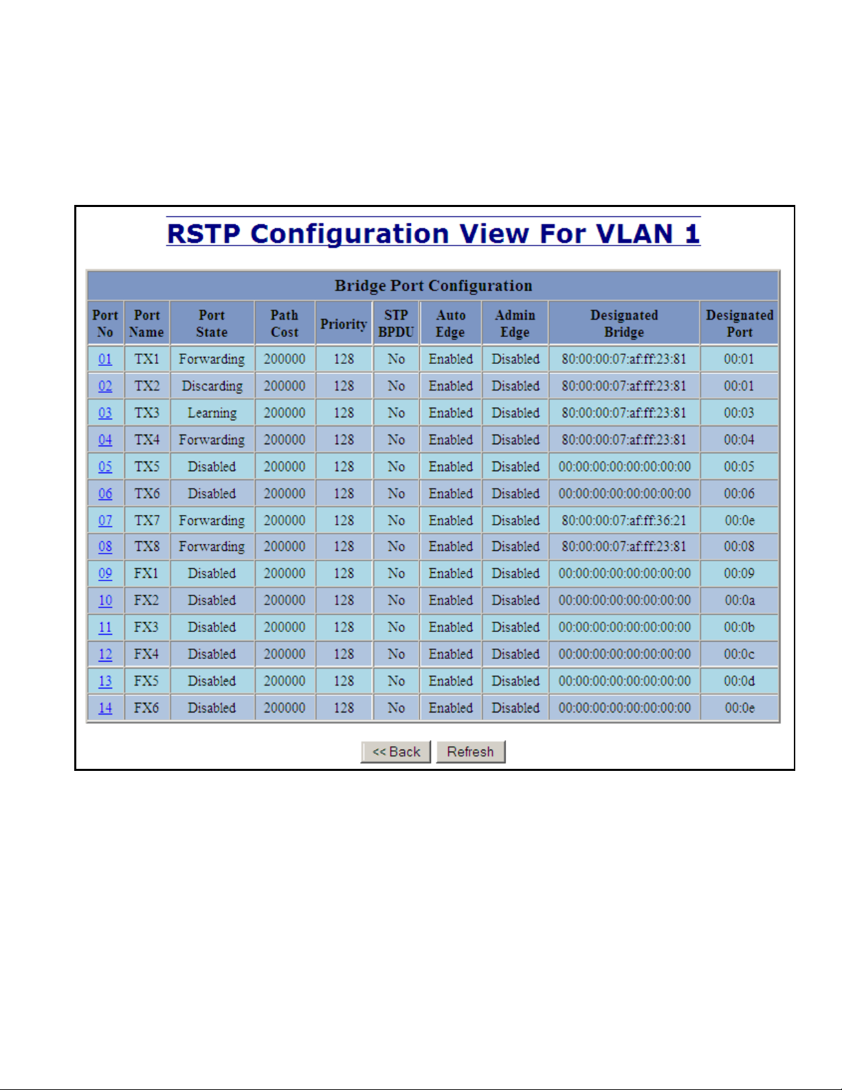
RSTP – Configuration Continued…
Following the link for the view RSTP Port Configuration at VLAN#, the administrator or user can see the
current RSTP status of the ports on that VLAN. This will show information such as the Path Cost and the
Port State. If the switch sees a redundant path it will put the port with the highest Path Cost into Blocking
mode where it will discard packets coming in on that port. In the example below, TX2 is a redundant port
with port TX1, therefore TX1 is forwarding and TX2 is discarding.
(Revised 2015-09-28) Page 77 of 161
Page 78
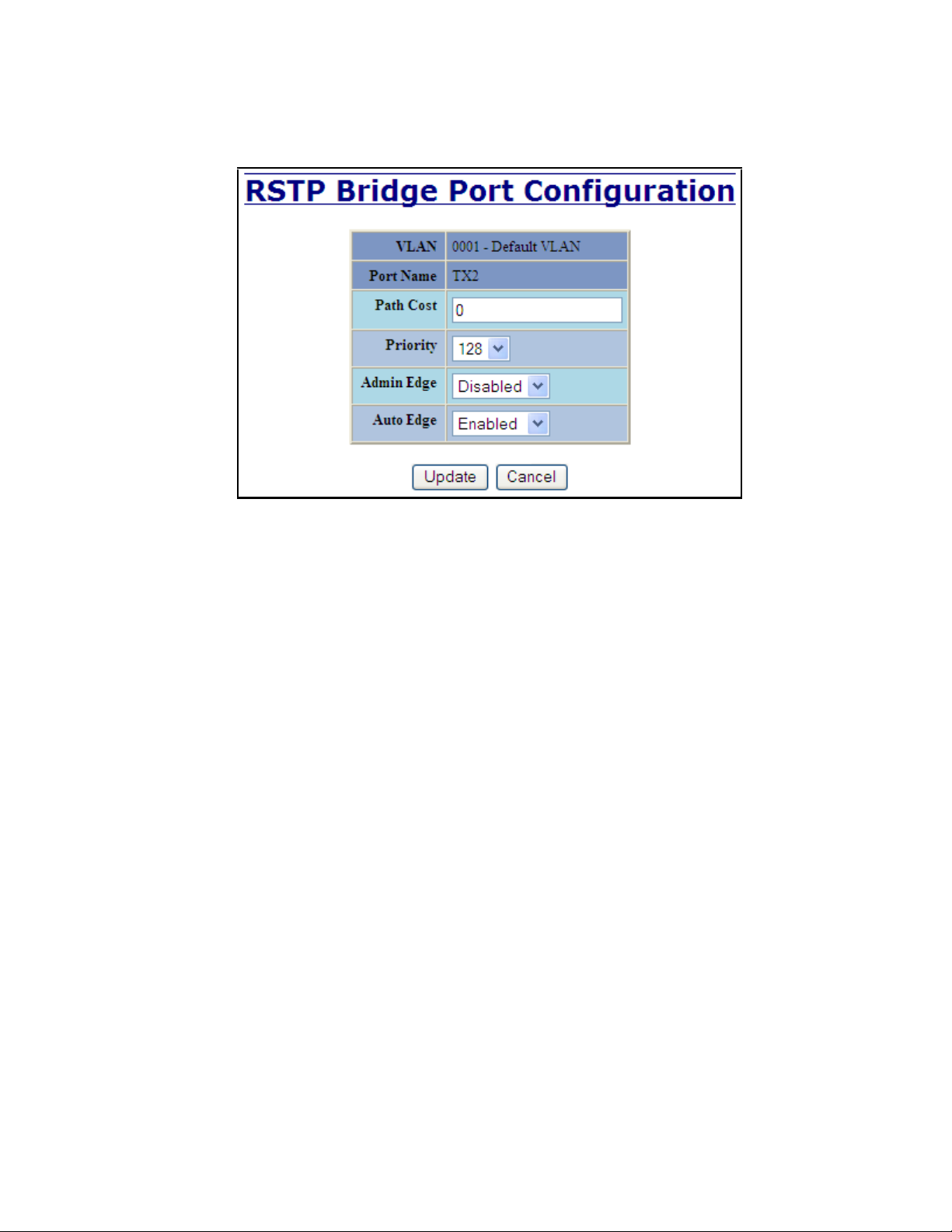
RSTP – Configuration Continued…
If the administrator selects one of the ports on the previous screen, he or she can change the Port’s Path
Cost, Priority, and the status of Admin Edge and Auto Edge.
(Revised 2015-09-28) Page 78 of 161
Page 79
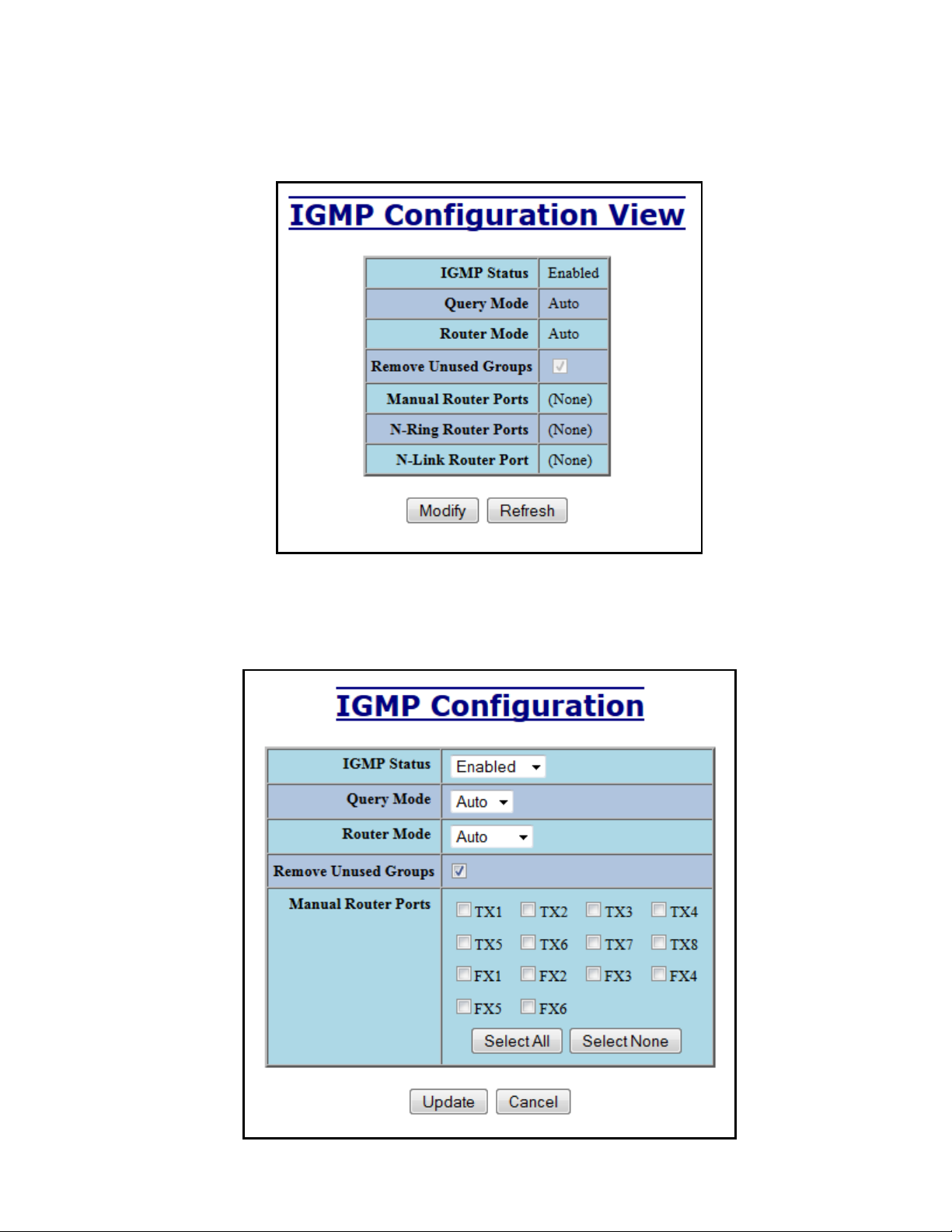
IGMP – Configuration
The Configuration tab under the IGMP category will display the IGMP basic configuration settings. By
default, IGMP is enabled.
Following the Modify button, the administrator will see a list of configurable fields for the IGMP
configuration. Once these fields are filled in to meet the needs of the administrator’s network, the changes
may be updated by clicking the Update button at the bottom of the page.
(Revised 2015-09-28) Page 79 of 161
Page 80
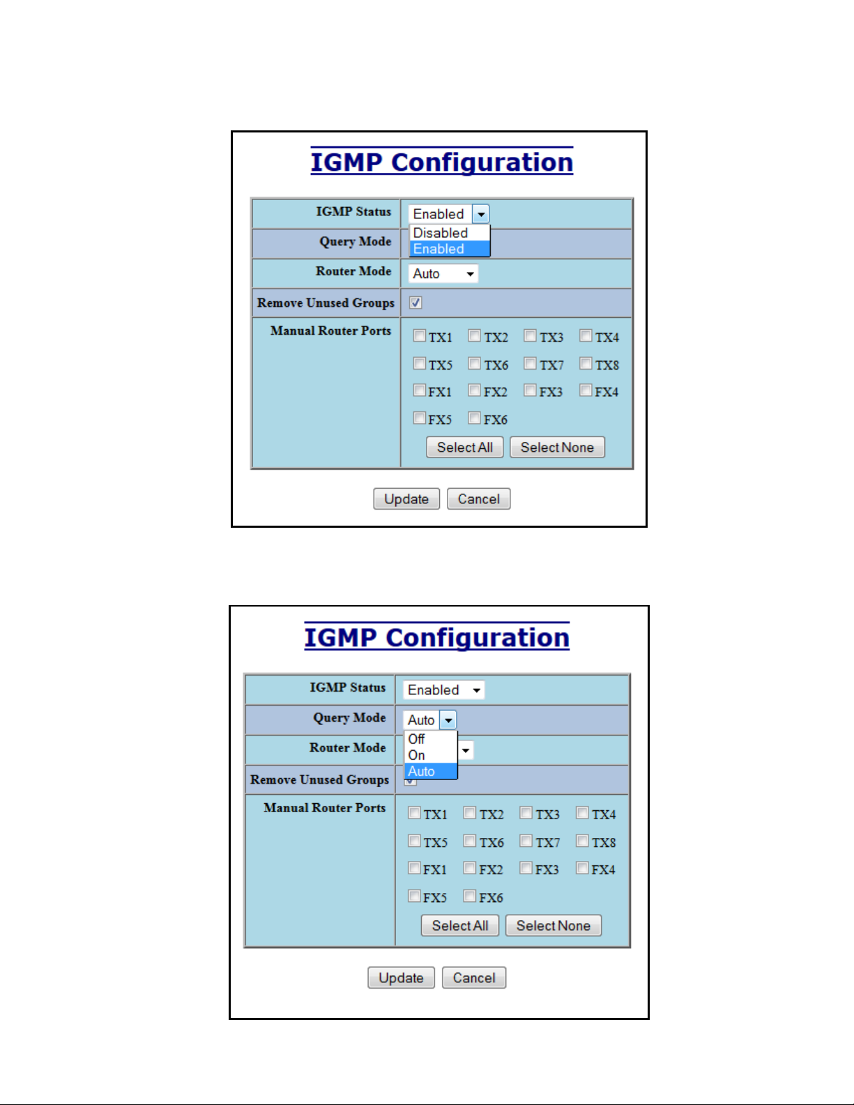
IGMP – Configuration, Continued…
The IGMP Status pull-down allows the user to enable or disable IGMP completely.
The Query Mode pull-down allows the user to set query mode for Automatic (the default), On (always), or
Off (never):
(Revised 2015-09-28) Page 80 of 161
Page 81

IGMP – Configuration, Continued…
The Router Mode pull-down allows the user to choose router mode. ‘Auto’ allows for dynamically detected
and manually set router ports. ‘Manual’ allows only for manually set router ports. ‘None’ allows no router
ports.
(Revised 2015-09-28) Page 81 of 161
Page 82

IGMP – Configuration, Continued…
If Remove Unused Groups is checked then unused IGMP Groups will be removed and traffic with those
multicast addresses will be treated as normal multicast. If unchecked, then unused IGMP Groups are not
removed and traffic with those multicast addresses will be limited. The default is checked. Note that IGMP
Groups are not retained through a power cycle.
The user can specify the manual router ports:
(Revised 2015-09-28) Page 82 of 161
Page 83

IGMP – Show Group and Show Router
The Show Groups tab under the IGMP category will display a list of IGMP groups based on the Group IP
and the port number that it is associated with.
The Show Routers tab under the IGMP category will display a list of Auto-detected Router IPs and the port
numbers that they are associated with.
(Revised 2015-09-28) Page 83 of 161
Page 84

IGMP – RFilter
The ‘rfilter’ (Router Multicast Data Filter) function allows you to choose whether or not DATA frames
with KNOWN group multicast addresses are sent to the ‘router’ ports (links to other switches). Control
packets (Join, Leave) will be sent to the router(s) regardless of this setting. “KNOWN” is known from
dynamic IGMP Snooping operations.
The factory default is that the Router Multicast Data Filter is enabled for all ports, so any router ports do
NOT get DATA frames with KNOWN multicast destination addresses unless a join to a specific multicast
address has been received on that port. Joins override an rfilter.
If rfilter is disabled, router ports do get DATA frames with KNOWN multicast destination addresses
Rfilter can be set for individual ports: any, all, or none. For each port, rfilter will have an impact only if that
port is manually or dynamically chosen as a router port.
Default configuration:
(Revised 2015-09-28) Page 84 of 161
Page 85

IGMP – RFilter, Continued…
Modifying rfilter port settings:
(Revised 2015-09-28) Page 85 of 161
Page 86
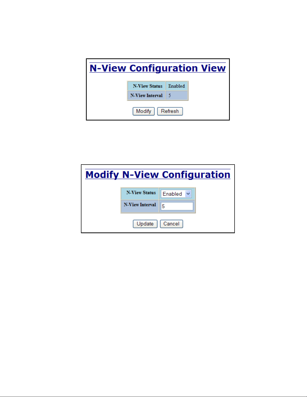
N-View – Configuration
The Configuration tab under the N-View category will display two basic variables for N-View, the status
and the interval between packets.
Following the Modify button on the above example, the administrator can modify the variable to change the
frequency with which N-View reports information. Increasing the interval will slow the update rate.
Decreasing the interval will allow N-View to report more frequently. Additionally, you may Disable or
Enable N-View altogether.
(Revised 2015-09-28) Page 86 of 161
Page 87

N-View – Ports
The Ports tab under the N-View category will display a list of all the configured ports on the 714FX6 unit
along with the ports transmitting multicast packets and MIB stats respectively.
(Revised 2015-09-28) Page 87 of 161
Page 88

N-View – Ports, Continued…
Following the Modify button on the above example, the administrator can modify these two variables to
enable or disable multicast out of the port and if MIB stats are sent out for those ports.
(Revised 2015-09-28) Page 88 of 161
Page 89

N-Ring – Configuration
The Configuration tab under the N-Ring category will display the N-Ring basic configuration settings. By
default, N-Ring is in Auto Member mode and the N-Ring Aging Time is 20 seconds.
Following the Modify button on the above example, the administrator will see a list of configurable fields
for the N-Ring configuration, as below.
The N-Ring Aging Time has a default of 20 seconds and is separate from the Bridging Aging Time. N-Ring
Aging Time is used when the switch is an N-Ring Manager or becomes an active N-Ring Member, and in
either case N-Ring status includes for example:
“Switch is currently using N-Ring Aging Time = 20 Seconds”
Once these fields are filled in to meet the needs of the administrator’s network, the changes may be saved by
clicking the Update button at the bottom of the page.
NOTES:
1. N-Ring Manager cannot have RSTP or Trunking enabled.
2. RSTP & N-Ring are different modes and cannot share links or segments along those lines.
See the examples in the RSTP configuration section.
3. Do not use Trunking on an N-Ring manager. Do not connect the N-Ring to actively Trunking
ports on an Auto Member.
4. Do not create redundant links unless either RSTP or N-Ring is enabled.
5. Any one 714FX6 can only participate in one N-Ring.
6. N-Ring copper ports must be run at 100Mb full duplex, including the default ‘autonegotiate’ as
long as all switches in the ring support 100Mb full duplex.
(Revised 2015-09-28) Page 89 of 161
Page 90

N-Ring – Configuration, Continued…
The “N-Ring Mode” is one of three, as below:
If N-Ring Mode is “Manager”, then a pull-down allows selection of available ports TX1/TX2, or FX1/FX2
(on 714FX6) as N-Ring ports.
(Revised 2015-09-28) Page 90 of 161
Page 91

N-Ring – Configuration, Continued…
If N-Ring Mode is “Manager”, then VLAN ID can be set to a unique VLAN id (1 ~ 4094). Default is 3333.
If N-Ring Mode is “Manager”, then a pull-down allows selection as to whether the N-Ring ports are
members of the VLAN’s Tagged or Untagged ports. Default is Tagged.
Once these fields are filled in to meet the needs of the administrator’s network, the changes may be saved by
clicking the Update button at the bottom of the page.
NOTES:
1. Since VLANs are implemented for security reasons as well as traffic flow, N-Ring only makes
minimal changes. It is up to the administrator to ensure that VLANs are configured correctly on the
N-Ring manager and all N-Ring members.
2. When the N-Ring manager and all N-Ring Members are in defaults, changing the N-Ring manager
to use a Tagged VLAN requires no user interaction to allow non-ring traffic to pass through the ring.
This works because changing to a Tagged VLAN does not remove the ring ports from the default
VLAN.
3. When the N-Ring manager and all N-Ring Members are in defaults, changing the N-Ring manager
to use an Untagged VLAN other than VID 1, requires the administrator to add non-ring ports to the
N-Ring VLAN to allow non-ring traffic to pass through the ring. This occurs because the N-Ring
ports must be removed from VID 1 because an untagged port may only be a member of one VLAN.
(Revised 2015-09-28) Page 91 of 161
Page 92

N-Ring – Advanced Configuration
If switch is an N-Ring Member, the following data will be shown:
N-Ring Mode
Current N-Ring mode of switch.
Keep-Alive Timeout:
Keep-Alive timeout is used when switch is active in an N-Ring. The range is 5-1000000 seconds.
If switch is an N-Ring Manager, the following advanced configuration data will be shown:
N-Ring Mode
Current N-Ring mode of switch.
Self Health Packet Interval:
The amount of time to wait in milliseconds before sending Self-Health packets. The default is 10.
Maximum Missed Packets
The number of missed Self-Health packets that constitute a fault. The default is 2.
Sign-On Delay
The amount of time to wait in milliseconds before requesting initial sign-on information from ring members. The default
is 1000.
Sign-On Match Packets
The number of times the switch count must match before starting the sign-on process. The default is 3.
Sign-On Interval
The interval of time to wait in milliseconds before requesting subsequent sign-on information from ring members when
the ring is broken. The default is 3000.
Sign-On Info Spacing Multiplier
The amount of time to wait in milliseconds, scaled by switch number, before sending information to the ring manager.
The default is 5.
Sign-On Info Retry Timeout
The amount of time the ring member will wait in milliseconds for the ring manager to acknowledge receipt of the
member's information before the member tries to re-send the information. The default is 1500.
Delay Before Re-Entering Broken State
The amount of time, in milliseconds, that must elapse before the ring is allowed to go back into the broken state. The
default is 3000.
(Revised 2015-09-28) Page 92 of 161
Page 93
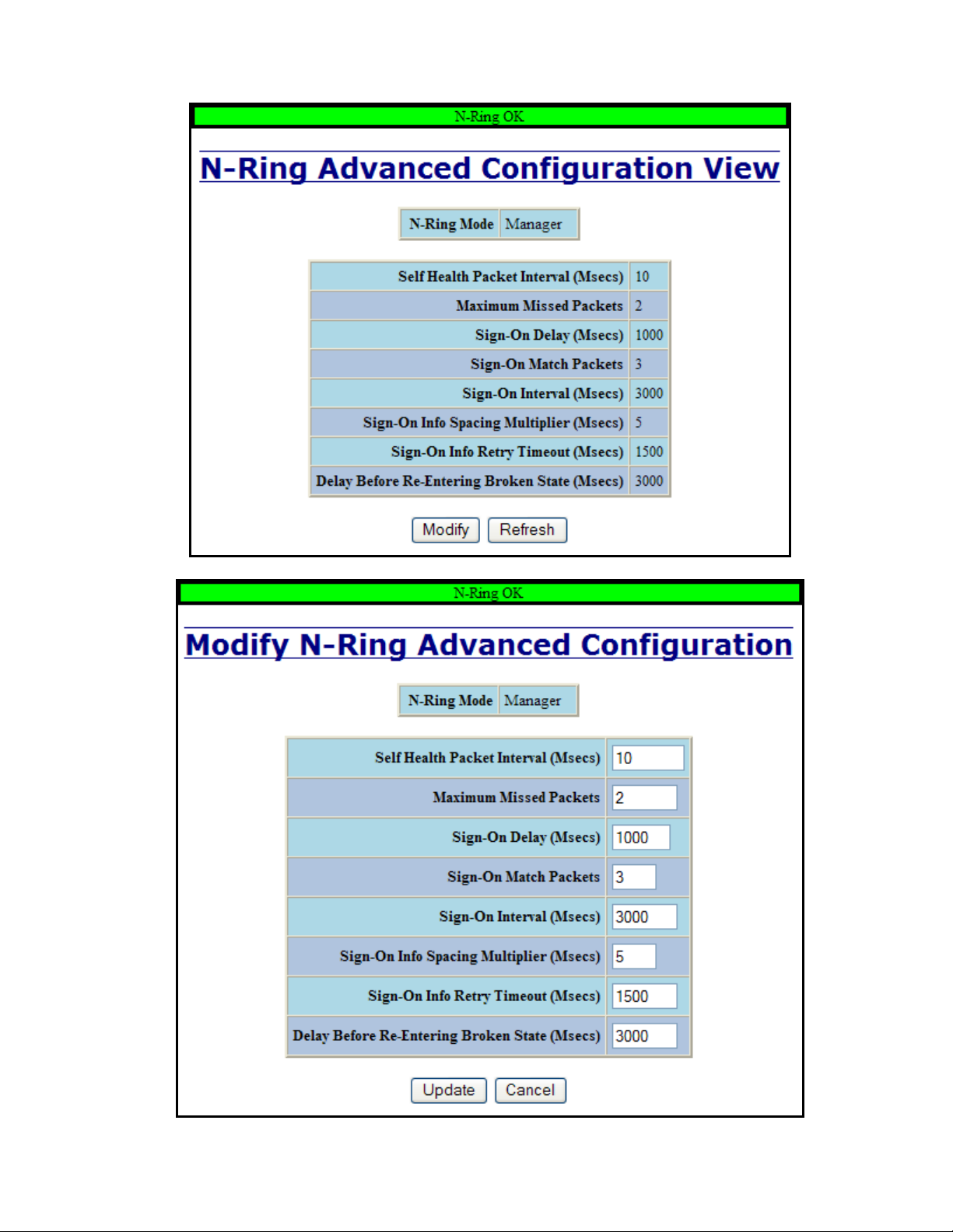
N-Ring – Advanced Configuration, Continued…
(Revised 2015-09-28) Page 93 of 161
Page 94

N-Ring – Status
The Status tab under the N-Ring category will display the N-Ring status.
Below is an example of N-Ring Status from a switch in defaults (N-Ring Auto Member) that is not an
N-Ring Manager and has not become an “Active” N-Ring Member:
Below is an example of N-Ring Status from an “Active” N-Ring Member:
(Revised 2015-09-28) Page 94 of 161
Page 95
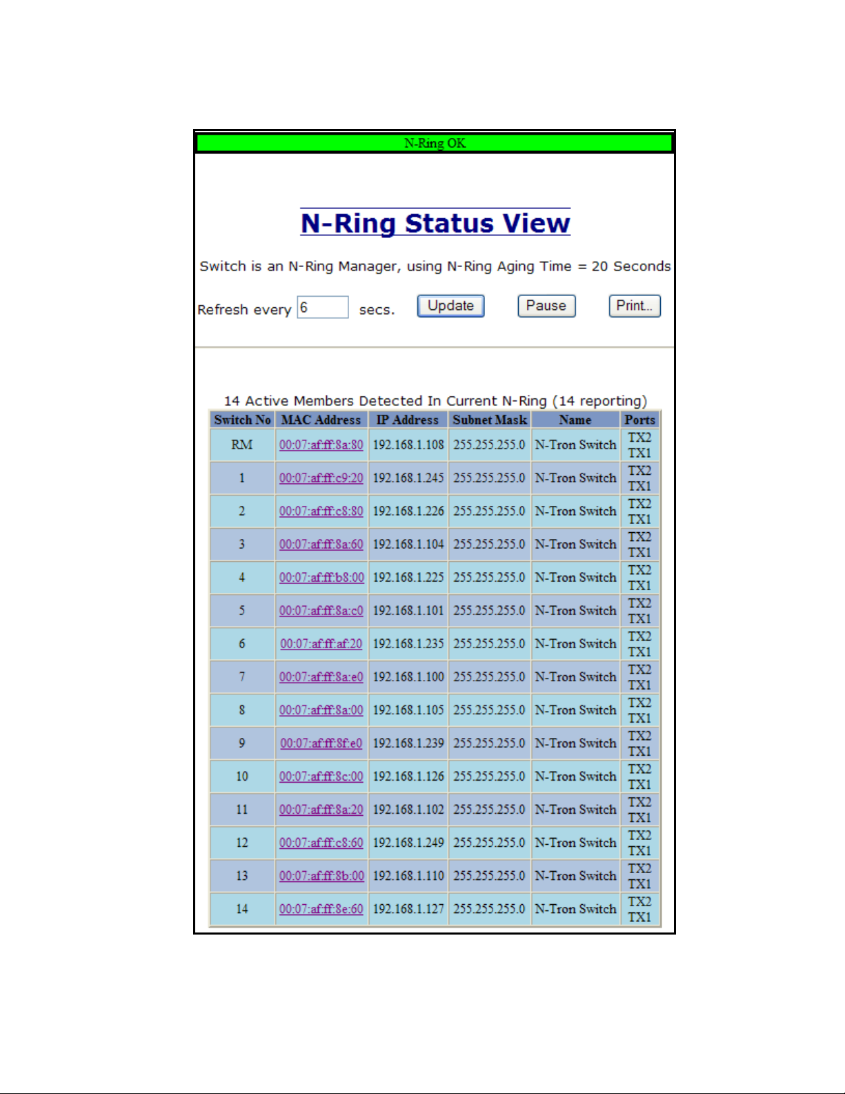
N-Ring – Status, Continued…
Below is an example of N-Ring Status from an N-Ring Manager with a healthy N-Ring:
(Revised 2015-09-28) Page 95 of 161
Page 96
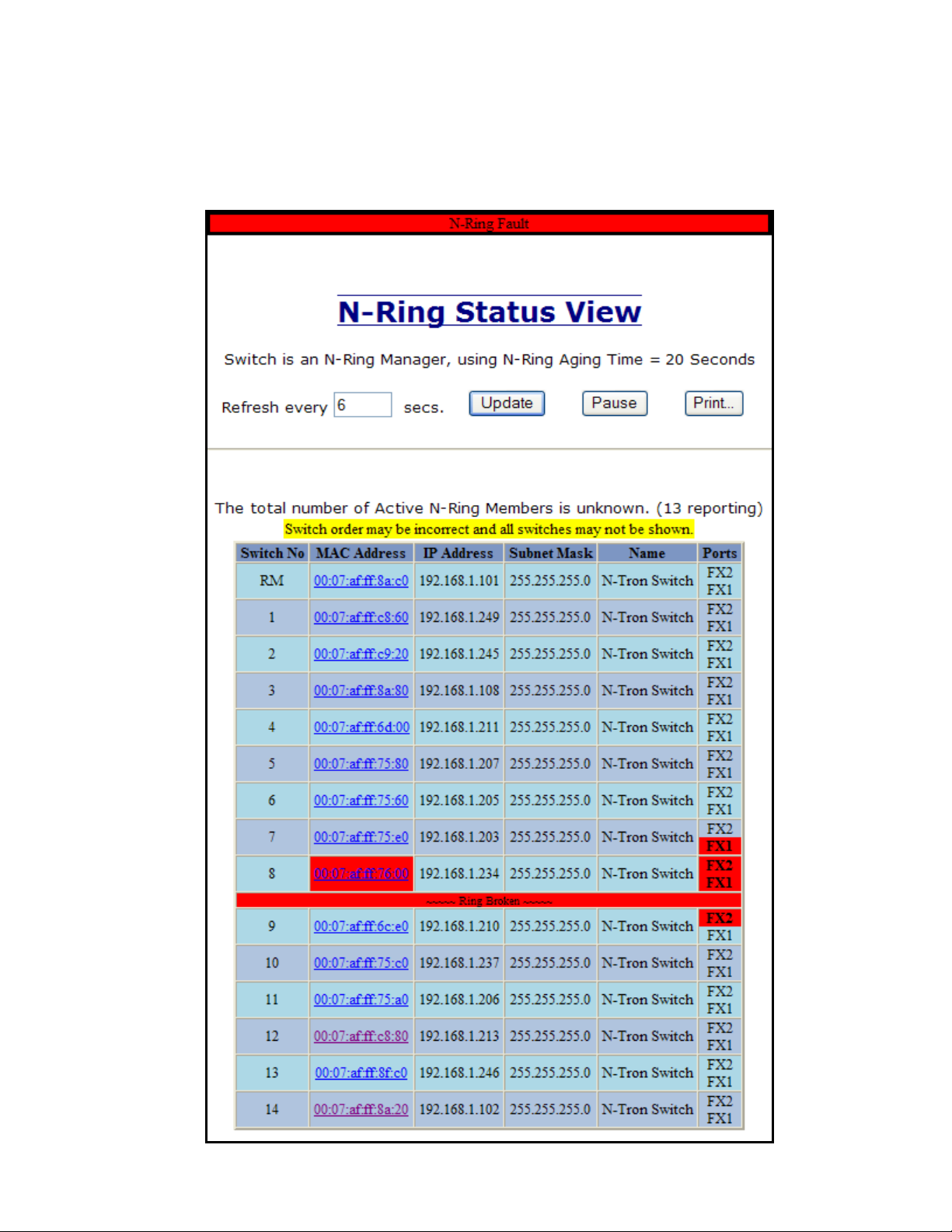
N-Ring – Status, Continued…
Below is an example of N-Ring Status from an N-Ring Manager with a faulted N-Ring. The red fields on
the N-Ring Map show problems. Ports that are red indicate that the port is not linked. MAC addresses that
are red indicate that there is no communication to that switch. The red “Ring Broken” line shows where the
N-Ring is broken.
(Revised 2015-09-28) Page 96 of 161
Page 97

N-Ring – Status, Continued…
In rare cases an N-Ring can have a “Partial Fault”. An example of this is to have a break in just one fiber in
a duplex channel fiber pair. The screenshot below shows N-Ring Manager Status when a ‘Higher’ N-Ring
Port (TX2 or FX2) is not receiving self health frames all the way around the N-Ring, though the other (low
TX1 or FX1) N-Ring port is:
The screenshot below shows N-Ring Manager Status when a ‘Lower’ N-Ring Port (TX1 or FX1) is not
receiving self health frames all the way around the N-Ring, though the other (high TX2 or FX2) N-Ring
port is:
(Revised 2015-09-28) Page 97 of 161
Page 98
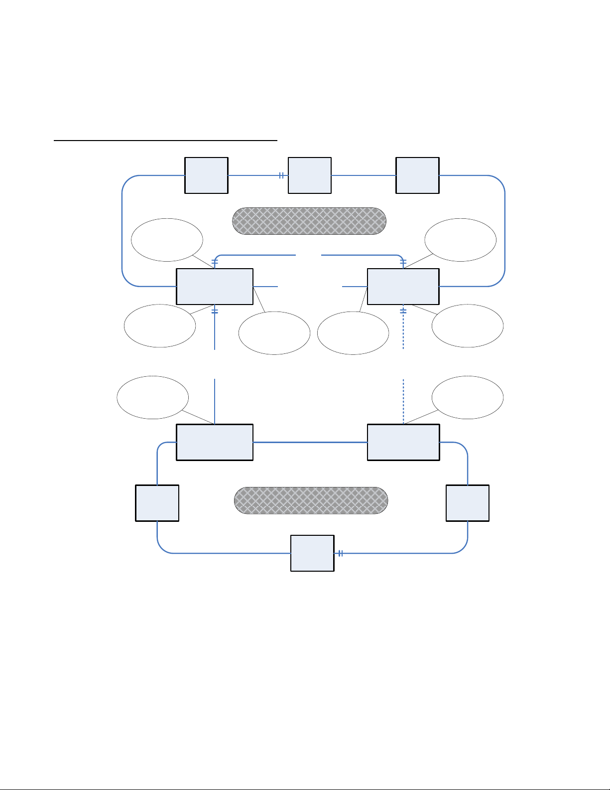
N-Link – Configuration
N-Rng
Manager
N-Ring
Auto
Member
N-Link Slave
N-Ring Member
N-Link Master
N-Ring Member
Partner Link
(N-Ring Segment)
Control
Link
N-Ring
Auto
Member
N-Rng
Manager
N-Link Coupler
N-Ring Member
N-Link Couper
N-Ring Member
N-Ring
Auto
Member
N-Ring
Auto
Member
Primary
Coupler
Link
Standby
Coupler
Link
Coupler Port
(Default: TX4)
Control Port
(Auto-Detected)
Coupler Port
(Default: TX4)
Control Port
Default: TX3
Partner Port
(Auto-Detcted)
Partner Port
(Auto-Detcted)
N-Ring #1
N-Ring #2
Coupler Port
(Auto-Detected)
Coupler Port
(Auto-Detected)
The purpose of N-Link is to provide a way to redundantly couple an N-Ring topology to one or more other
topologies, usually other N-Ring topologies. Each N-Link configuration requires 4 switches: N-Link
Master, N-Link Slave, N-Link Primary Coupler, and N-Link Standby Coupler.
Standard N-Link Configuration (Example):
For convenience, a diagram similar to the above is provided in the switch’s browser help for N-Link.
(Revised 2015-09-28) Page 98 of 161
Page 99

N-Link – Configuration, Continued…
N-Ring #1
N-Ring AM
N-Link Slave
#1
N-Ring AM
N-Link Master
#1
Partner
Link #1
Control
Link #1
N-Rng
Manager
N-Link AC
N-Ring AM
N-Link AC
N-Ring AM
N-Ring
Auto
Member
Primary
Coupler
Link #1
Standby
Coupler
Link #1
N-Ring #2
N-Ring
Auto
Member
N-Ring AM
N-Link Slave
#2
N-Ring AM
N-Link Master
#2
Partner
Link #2
Control
Link #2
N-Rng
Manager
N-Link AC
N-Ring AM
N-Link AC
N-Ring AM
N-Ring
Auto
Member
Primary
Coupler
Link #2
Standby
Coupler
Link #2
N-Ring #3
N-Ring
Auto
Member
N-Ring AM
N-Link Slave
#3
N-Ring AM
N-Link Master
#3
Partner
Link#3
Control
Link #3
N-Rng
Manager
N-Link AC
N-Ring AM
N-Link AC
N-Ring AM
N-Ring
Auto
Member
Primary
Coupler
Link #3
Standby
Coupler
Link #3
N-Ring #4
N-Ring
Auto
Member
N-Ring
Auto
Member
N-Ring
Auto
Member
N-Rng
Manager
Complex N-Link Configuration (Example):
Configuration Notes:
The Master and Slave must be part of the N-Ring topology.
If using default configuration choices, the administrator only needs to configure the N-Link Master.
The N-Link Slave and both Coupler switches will auto-detect any needed configuration.
If not using default configuration choices, the administrator may also need to configure the Default
Coupler port on the N-Link Slave.
There must be a direct link between the Master and Slave Control ports. Use of media converters or
other switches is not supported.
There must be a direct link between the Master and Slave Partner ports. Use of media converters or
other switches is not supported.
There must be at least one other switch, besides the Master and Slave, that supports N-Link on the
N-Ring.
N-Link will only support a single point of failure. Multiple points of failure and misconfiguration
are not supported and may cause a network storm under some circumstances.
Configuration Steps to redundantly couple 2 N-Ring networks:
1. Ensure the Coupler and Control cables are disconnected at this point.
2. Get Both N-Rings working with a status of OK.
3. Configure N-Link Slave: Ensure that the N-Link Slave is set to Auto Configure and select a Default
Coupler Port. Save Configuration.
4. Configure N-Link Master: Select the Control and Coupler ports. Save the Configuration.
5. Connect the Control Link cable. Ensure that the Slave switch status now shows a state of “Slave”
6. Connect the Coupler Link cables.
7. Check N-Link status by selecting the N-Link Status View page.
(Revised 2015-09-28) Page 99 of 161
Page 100

N-Link – Configuration, Continued…
The Configuration tab under the N-Link category will display the configuration settings. By default, NLink is in Auto Configure mode and will use TX4 as the Default Coupler port.
Following the Modify button on the above example, the administrator will see a list of configurable fields
for the N-Link configuration, as below.
The port configured as the Default Coupler Port will be used as the Standby Coupler port if the switch
detects an N-Link Master and becomes an N-Link Slave.
Once these fields are filled in to meet the needs of the administrator’s network, the changes may be saved by
clicking the Update button at the bottom of the page.
(Revised 2015-09-28) Page 100 of 161
 Loading...