

Page 1
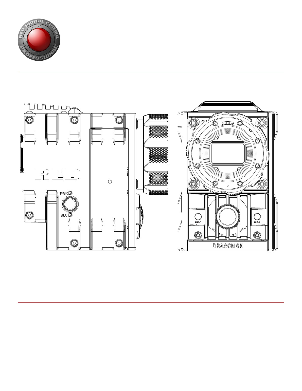
EPIC/SCARLET
OPERATION GUIDE
EPIC | SCARLET | V6.2
RED DRAGON | MYSTERIUM-X | MONOCHROME
RED.COM
Page 2

EPIC/SCARLET OPERATION GUIDE
TABLE OF CONTENTS
Disclaimer 3
Copyright Notice 3
Trademark Disclaimer 3
Compliance Statements 4
Safety Instructions 6
Battery Storage and Handling 7
Shipping Disclaimer 7
Chapter 1: Camera Introduction 8
Read Before You Shoot 9
R3D File Format and REDCODE 9
Shoot For Video and Stills 9
Post Production with REDCINE-X PRO 10
HDRx and MAGIC MOTION 10
Additional Resources 11
Chapter 2: Camera System Components 12
Additional Resources 12
BRAIN 13
Media Modules 14
REDMAG and RED MINI-MAG Systems 16
Adaptor Modules 17
Power Modules 19
RED Batteries and Chargers 20
Other Modules 20
Displays and Electronic Viewfinders 22
LEMO Adaptors 26
Camera Control Modules 27
Lens Mounts 30
Interchangeable OLPFs 31
Rails, Mounts, Tactical Gear, and Cables 31
Chapter 3: Basic Operations 32
Power Operations 32
Configure Your Camera 34
Interchangeable OLPF System 41
Use a Tripod or Monopod 45
Video Monitor Outputs 46
Record 46
Chapter 4: Basic Menus and Controls 48
GUI Menu Introduction 48
Upper Status Row (Basic Menu) 49
Live Action Area 53
Lower Status Row 54
Navigation Controls 59
Chapter 5: Advanced Menus 66
Advanced Menus 66
Settings Menu 67
Media Menu 118
Playback Menu 119
Power Menu 121
HDRX Menu 123
Focus Menu 124
Exposure Assist 129
Presets Menu 131
Chapter 6: Record and Monitor Audio 134
Overview 134
Audio Data Path 134
Set Up Audio 135
Audio Input (Source) Options 135
Audio Output Options 137
Control Headphone Volume (BRAIN) 138
Audio Meter (VU Meter) 139
Audio During Playback 140
Chapter 7: REDMOTE Operation 141
Overview 141
Controls, Connectors, and LEDs 142
REDMOTE Basics 144
REDMOTE LCD Display Menu 147
Upgrade REDMOTE Firmware 148
Chapter 8: Timecode, Genlock, Multi-Camera Setup 151
Timecode 151
Genlock 153
Master/Slave Operation 157
Set Up Stereo/3D Configuration 160
Set Up a Camera Array 161
Set Up Motion Control (MoCo) 163
Compatible Devices 165
Chapter 9: Upgrade Camera Firmware 166
Verify Current Camera Firmware 166
Upgrade Camera Firmware 166
Chapter 10: Camera System Maintenance 168
BRAIN and Accessory Exterior Surfaces 168
Clean the Camera Sensor or OLPF 169
Clean EVF Screen 169
Clean LCD Screens 170
Water Damage 170
Adjust Back Focus 171
Chapter 11: Troubleshoot Your Camera 172
Perform a Stress Test 172
General Troubleshooting 172
Appendix A: Technical Specifications 181
EPIC DRAGON 181
SCARLET DRAGON 183
EPIC MYSTERIUM-X 185
SCARLET MYSTERIUM-X 186
BRAIN Dimensions 187
Appendix B: Input/Output Connectors 197
Record/Monitor Out Ports 198
Communication Ports 199
Audio Ports 203
Power Ports 204
SSD Module Connectors 204
Appendix C: Lens Mounts and Lenses 205
Lens Mounts 205
Lenses 208
Appendix D: Default Key Functions 215
Preset Default Key Functions 218
Appendix E: Menu Map 219]
COPYRIGHT © 2016 RED.COM, INC
955-0020_V6.2, REV-J | 2
Page 3

EPIC/SCARLET OPERATION GUIDE
DISCLAIMER
RED® has made every effort to provide clear and accurate information in this document, which is provided solely for the user’s information. While thought to be accurate, the information in this document is provided strictly “as is” and RED will not be held responsible
for issues arising from typographical errors or user’s interpretation
of the language used herein that is different from that intended by
RED. All safety and general information is subject to change as a
result of changes in local, federal or other applicable laws.
RED reserves the right to revise this document and make changes
from time to time in the content hereof without obligation to notify
any person of such revisions or changes. In no event shall RED, its
employees or authorized agents be liable to you for any damages
or losses, direct or indirect, arising from the use of any technical or
operational information contained in this document.
For comments or questions about content in this document, please
send a detailed email to [email protected].
COPYRIGHT NOTICE
COPYRIGHT© 2016 RED.COM, INC.
All trademarks, trade names, logos, icons, images, written material,
code, and product names used in association with the accompanying product are the copyrights, trademarks, or other intellectual
property owned and controlled exclusively by RED.COM, INC.
TRADEMARK DISCLAIMER
All other company, brand, and product names are trademarks or
registered trademarks of their respective holders. RED has no affiliation to, is not associated with or sponsored by, and has no express rights in third-party trademarks. Adobe and Adobe Premiere
Pro are registered trademarks of Adobe Systems Incorporated. AJA
is a registered trademark of AJA Video Systems, Inc. Cooke and
S4/i are registered trademarks of Cooke Optics Limited. DaVinci
is a registered trademark of Blackmagic Design in the U.S. and
other countries. Distagon, Makro-Planar, and Otus are registered
trademarks of Carl Zeiss AG. Fujinon is a registered trademark of
FUJIFILM CORPORATION. HDMI is a registered trademark of HDMI
Licensing LLC in the United States and other countries. Leica is a
registered trademark of Leica Microsystems. Loctite is a registered
trademark of Henkel AG & Company KGaA. Nikkor and Nikon are
registered trademarks of Nikon Corporation. Canon is a registered
trademark of Canon, U.S.A. Apple, Macintosh, Final Cut Pro, and
QuickTime are registered trademarks of Apple Inc. in the U.S. and
other countries. Windex is a registered trademark of S. C. Johnson
& Son, Inc. Windows is a registered trademark of Microsoft Corporation. LEMO is a registered trademark of LEMO USA. Sony is
a registered trademark of Sony Corporation. TORX is a registered
trademark of Acument Intellectual Properties, LLC in the United
States or other countries. IOS is a registered trademark of Cisco
in the U.S. and other countries. Avid is a registered trademark of
Avid Technology, Inc. DaVinci Resolve is a registered trademark of
Blackmagic Design in the U.S. and other countries. EDIUS Pro is
a registered trademark of Grass Valley. Vegas Pro is a registered
trademark of Sony Creative Software. IDX is a registered trademark
of IDX Company, Ltd.
COPYRIGHT © 2016 RED.COM, INC 955-0020_V6.2, REV-J | 3
Page 4
EPIC/SCARLET OPERATION GUIDE
COMPLIANCE STATEMENTS
INDUSTRIAL CANADA EMISSION COMPLIANCE STATEMENTS
This device complies with Industry Canada license-exempt RSS
standards RSS 139 and RSS 210. Operation is subject to the following two conditions: (1) this device may not cause interference, and
(2) this device must accept any interference, including interference
that may cause undesired operation of the device.
This Class B digital apparatus complies with Canadian ICES-003.
Le présent appareil est conforme aux CNR d’Industrie Canada ap-
plicables aux appareils radio exempts de licence. L’exploitation est
autorisée aux deux conditions suivantes : (1) l’appareil ne doit pas
produire de brouillage, et (2) l’utilisateur de l’appareil doit accepter
tout brouillage radioélectrique subi, même si le brouillage est susceptible d’en compromettre le fonctionnement.Cet appareil numérique de la classe B est conforme à la norme NMB-003 du Canada.
FEDERAL COMMUNICATIONS COMMISSION (FCC) STATEMENTS
This equipment has been tested and found to
comply with the limits for a Class B digital device, pursuant to part 15 of the FCC Rules.
These limits are designed to provide reasonable protection against harmful interference
in a residential installation. This equipment
generates, uses and can radiate radio fre-
quency energy and, if not installed and used
in accordance with the instructions, may cause harmful interference
to radio communications. However, there is no guarantee that interference will not occur in a particular installation. If this equipment
does cause harmful interference to radio or television reception,
which can be determined by turning the equipment off and on, the
user is encouraged to try to correct the interference by one or more
of the following measures:
Reorient or relocate the receiving antenna.
Increase the separation between the equipment and receiver.
Connect the equipment into an outlet on a circuit different from
that to which the receiver is connected.
Consult the dealer or an experienced radio/TV technician for
help.
In order to maintain compliance with FCC regulations, shielded
cables must be used with this equipment. Operation with non-approved equipment or unshielded cables is likely to result in interference to radio and TV reception. The user is cautioned that changes
and modifications made to the equipment without the approval of
manufacturer could void the users authority to operate this equipment.
NOTE: This device complies with Part 15 of the FCC Rules.
Operations subjected to the following two conditions (1) this device
may not cause harmful interference, and (2) this device must accept
any interference received, including that may cause undesirable interference.
CAUTION: Exposure to Radio Frequency Radiation.
CAUTION: Regulations of the FCC and FAA
prohibit airborne operation of radio-frequency
wireless devices because there signals could
interfere with critical aircraft instruments.
CAUTION: If the device is changed or modified
without permission from RED, the user may
void his or her authority to operate the equipment.
AUSTRALIA AND NEW ZEALAND STATEMENTS
RED declares that the radio equipment described in this document
comply with the following international standards.
IEC 60065 - Product Safety
ETSI EN 300 328 - Technical requirement for radio equipment
RED declares digital devices described in this document comply
with the following Australian and New Zealand standards.
AS/NZS CISPR 22 – Electromagnetic Interference
AS/NZS 61000.3.2 – Power Line Harmonics
AS/NZS 61000.3.3 – Power Line Flicker
JAPAN STATEMENTS
This is a Class B product based on the
standard of the Voluntary Control Council
for Interference (VCCI) for information technology equipment. If this equipment is used
near a radio or television receiver in a domestic environment, it may cause radio interference. Install and use the equipment
according to the instruction manual.
EUROPEAN UNION COMPLIANCE STATEMENTS
RED declares that the radio
equipment described in this
document comply with the
R&TTE Directive (1999/5/
EC) issued by the Commission of the European Community.
Compliance with this directive implies conformity to the following
European Norms (in brackets are the equivalent international standards).
EN 60065 (IEC 60065) – Product Safety
ETSI EN 300 328 Technical requirement for radio equipment
ETSI EN 301 489 General EMC requirements for radio equip-
ment.
The device shall be used in such a manner that the potential for human contact is minimized
This equipment complies with FCC radiation exposure limits set
forth for an uncontrolled environment. This equipment should be
installed and operated with a minimum distance of 20 cm between
the radiator and your body.
COPYRIGHT © 2016 RED.COM, INC
955-0020_V6.2, REV-J | 4
Page 5

EPIC/SCARLET OPERATION GUIDE
INFORMATION
Products with the CE marking comply with the EMC Directive
(2004/108/EC) and the Low Voltage Directive (2006/95/EC) issued
by the Commission of the European Community. Compliance with
these directives implies conformity to the following European Product Family Standards.
EN 55022 (CISPR 22) – Electromagnetic Interference
EN 55024-1 (CISPR 24) – Electromagnetic Immunity
EN 61000-3-2 (IEC610000-3-2) – Power Line Harmonics
EN 61000-3-3 (IEC610000) – Power Line Flicker
EN 60065 (IEC60065) – Product Safety
WASTE ELECTRICAL AND ELECTRONIC EQUIPMENT (WEEE)
The Waste Electrical and Electronic Equip-
ment (WEEE) mark applies only to countries
within the European Union (EU) and Norway.
This symbol on the product and accompany-
ing documents means that used electrical
and electronic products should not be mixed
with general household waste. For proper
treatment, recovery and recycling, please
take this product to designated collection
points where it will be accepted free of
charge. Alternatively, in some countries you
may be able to return your products to your
local retailer upon purchase of an equivalent
new product.
Disposing of this product correctly will help save valuable resources
and prevent any potential negative effects on human health and the
environment, which could otherwise arise from inappropriate waste
handling. Please contact your local authority for further details of
your nearest designated collection point. Penalties may be applicable for incorrect disposal of this waste, in accordance with you
national legislation.
For business users in the European Union, if you wish to discard
electrical and electronic equipment, please contact your dealer or
supplier for further information.
NORWAY
This subsection does not apply for the geographical area within a
radius of 20 km from the centre of Ny-Ålesund
Dette gjelder ikke for det geografiske området innenfor en radius av
20 km fra sentrum av Ny-Ålesund
RESPONSIBLE PARTY
RED Digital Cinema
34 Parker
Irvine, CA 92618
USA
USAGE RESTRICTIONS FOR PRODUCTS THAT INCORPORATE
REDLINK
Products that fall into this category are denoted
by inclusion of the Class 2 identifier symbol (exclamation mark in a circle) accompanying the CE
Mark on the products regulatory label, example to
the left.
FRANCE
Usage Restrictions - Geographic Area Where Restriction Applies :
France
For mainland France
2.400 - 2.4835 GHz (Channels 1-16) authorized for indoor use
2.400 - 2.454 GHz (Channels 1-10) authorized for outdoor use
Restrictions d’utilisation - Zone géographique où les restrictions
s’appliquent : France
Pour la France métropolitaine
2.400 - 2.4835 GHz (Canaux 1 à 16) autorisé en usage intérieur
2.400 - 2.454 GHz (canaux 1 à 10) autorisé en usage extérieur
COPYRIGHT © 2016 RED.COM, INC 955-0020_V6.2, REV-J | 5
Page 6
EPIC/SCARLET OPERATION GUIDE
SAFETY INSTRUCTIONS
DO NOT use the camera or accessories near water. Avoid ex-
posing your camera to moisture. The unit is not waterproof,
so contact with water could cause permanent damage to the
unit as well as electric shock and serious injury to the user. DO
NOT use the camera in the rain or under other conditions with
high moisture without appropriate protection, and immediately
remove power source if camera or accessories are exposed to
moisture.
WARNING: To reduce the risk of fire or electric shock, do not expose the camera to
rain or moisture.
DO NOT expose the camera to laser beams, as laser beams
may damage the sensor.
DO NOT expose your camera to excessive vibration or impact
(shock). Be careful not to drop your camera. Internal mechanisms may be damaged by severe shock. Mechanical alignment
of optical elements may be affected by excessive vibration.
ELECTROMAGNETIC INTERFERENCE: The use of devices us-
ing radio or other communication waves may result in the malfunction or interference with the unit and/or with audio and
video signals.
Clean only using a dry cloth. When cleaning your camera, re-
member that it is not waterproof and moisture can damage
electronic circuitry. DO NOT rinse or immerse any element
of the camera, lens or other accessory, keep them dry at all
times. DO NOT use soaps, detergents, ammonia, alkaline
cleaners, and abrasive cleaning compounds or solvents. These
substances may damage lens coatings and electronic circuitry.
Maintain sufficient ventilation—DO NOT block any ventilation
openings or obstruct cooling fan airflow.
CAUTION: Proper camera ventilation requires a minimum 0.5" (1.25 cm) clearance
between the camera ventilation openings
and external surfaces. Verify that objects
that can block the fan intake and exhaust ports do not impede airflow. Failure
to permit adequate airflow may result in
overheating of the camera, degraded operation and in extreme situations, damage
to the camera.
DO NOT operate or store near any heat sources such as radia-
tors, heat registers, stoves, or any other apparatus that produce heat. Store in a protected, level and ventilated place.
Avoid exposure to temperature extremes, damp, severe vibration, strong magnetic fields, direct sunlight or local heat sources during storage. Remove any batteries from the camera before storage. Recommended storage and usage temperatures
for your camera, lenses and other accessories are:
‒ Operating range: 0°C to 40°C (32°F to 104°F)
‒ Storage range: –20°C to 50°C (–4°F to 122°F)
If there are any performance issues with your camera or accessories when operating within this temperature range, please
file a support ticket on https://support.red.com.
Modules and lens mounts are NOT HOT SWAPPABLE, meaning
you cannot remove or install these items while the camera is
turned on. Before installing or removing these items, you MUST
turn off the camera. Failure to do so may result in damage to
the item or camera that is not covered under warranty.
DO NOT bypass the third prong of the grounding-type plug on
the power cord of the DSMC AC Power Adaptor. A groundingtype plug has two blades and a third “grounding” prong. The
third prong is provided for your safety. A grounding-type plug
shall be connected to an outlet with a protective earthen connection. If the grounding-type plug does not fit into your outlet,
do not attempt to modify the plug or outlet, consult a qualified
electrician.
Protect all power cords from being pinched, walked on or
driven over by a vehicle. Replace any power cords suspected
of sustaining damage due to crushing or other forms physical
damage.
Products marked with this symbol are
class 2 devices. These devices are not
provided with a grounding type plug.
CAUTION: The power cord plug for the
DSMC AC Power Adaptor is used as the
power disconnect. To disconnect all power
from the DSMC AC Power Adaptor, unplug
the power cord plug from the wall outlet.
During use, the power cord plug should
remain easily accessible at all times.
Lithium-ion batteries may be subject to special handling re-
quirements pursuant to federal and local laws. Please refer to
specific shipping instructions included with your battery regarding proper transport of your battery. Do not handle your
battery if it is damaged or leaking. Disposal of batteries must
be in accordance with local environmental regulations. For
example, California law requires that all rechargeable batteries must be recycled by an authorized recycle center. Storing
batteries fully charged or in high temperature conditions may
permanently reduce the life of the battery. Available battery
capacity may also be temporarily lessened after storage in low
temperature conditions.
WARNING: DO NOT expose the battery to
excessive heat.
WARNING: Danger of explosion if an incorrect battery is charged with the RED Charger or is used to power the camera and
accessories. Replace only with the same
or equivalent type battery.
CAUTION: Refer all service and repair to
qualified RED service personnel. To reduce
the risk of electric shock, and damage to
the camera or accessories, DO NOT attempt to perform any servicing other than
any procedures that are recommended in
the operating instructions.
INDOOR USE ONLY: Products marked with
this symbol are designed for use indoors
only.
COPYRIGHT © 2016 RED.COM, INC
955-0020_V6.2, REV-J | 6
Page 7
EPIC/SCARLET OPERATION GUIDE
BATTERY STORAGE AND HANDLING
WARNING: Failure to read, understand, and fol-
low these instructions may result in overheating, chemical leakage, smoke emission, fire, or
other potentially harmful results.
Always follow proper battery handling and storage practices. Improper handling and/or failure to abide by proper storage instructions may cause permanent damage to batteries, or degrade battery
charge holding capacity. Improper handling practices or failure to
comply with instructions may also put you at risk.
Lithium-Ion batteries, like the REDVOLT
®
, self-discharge over time. When storing for long periods
BRICK
of time, store batteries separately from the camera or charger and
remember to charge batteries to a capacity level of 40% to 60%. If
batteries will be stored for long periods of time, RED recommends
that you check the charge level at least once every six (6) months,
and recharge batteries to a capacity level of 40% to 60%.
When not in use, remove the battery from the camera or charger and
store the battery in a cool, dry place. Avoid extreme hot temperatures (such as inside a hot car), corrosive gas, and direct sunlight.
The optimal storage temperature for batteries is between –20°C to
20°C (–4°F to 68°F).
WARNING: Batteries stored in a discharged state
for long periods of time may self-discharge and
lose the ability to hold a charge.
WARNING: If recharging operation fails to complete even when a specified recharging time
has elapsed, immediately stop further recharging.
DO NOT store batteries in a fully charged state for extended
DO NOT store batteries in a fully charged state for extended
periods of time.
DO NOT store batteries in a fully discharged state for extended
periods of time.
DO NOT store batteries in the camera, in a camera module, or
in a charger for extended periods of time.
DO NOT use batteries for purposes other than their intended
use.
DO NOT store batteries in extreme hot or cold temperatures.
DO NOT store batteries in direct sunlight.
DO NOT use third-party chargers with your RED batteries.
DO NOT disassemble or modify the battery.
DO NOT overcharge batteries. Overcharging may increase in-
ternal temperature beyond the recommended limits and cause
permanent damage to the battery.
DO NOT connect the positive (+) and negative (–) terminals to
a metal object such as a wire.
DO NOT transport or store the battery together with metal ob-
jects such as jewelry, hairpins, etc. as they may generate heat
if they come into contact with the battery.
DO NOT discard the battery into fire or heat.
DO NOT store, use, or recharge the battery near a heat source
such as a fire or a heater.
DO NOT allow the battery to get wet.
®
, REDVOLT XL, and RED
DO NOT pierce the battery with pointed or other sharp objects.
DO NOT step on, throw, or strike the battery with a hammer.
DO NOT use a battery that appears to be deformed or dam-
aged.
DO NOT directly solder the battery.
DO NOT put the battery into a microwave oven or a pressur-
ized container.
DO NOT use or subject the battery to intense sunlight or hot
temperatures such as in a car in hot weather.
DO NOT use it in a location where static electricity may be
present.
DO NOT exceed the recharging temperature range of 0˚C to
40˚C (32˚F to 104˚F).
RED recommends that you only use RED chargers to recharge
RED batteries.
Store the battery in a location where children cannot reach it.
If the battery leaks or gives off a bad odor, discontinue use
immediately.
If the battery gives off an odor, generates heat, becomes dis-
colored or deformed, or in any way appears abnormal dur-
ing use, recharging or storage, immediately remove it from the
equipment or battery charger and discontinue use.
If electrolyte begins leaking from the battery and comes into
contact with your skin or clothing, immediately wash it away
with running water. Failure to do this may result in skin inflam-
mation.
If the battery leaks and the electrolyte reaches the eyes, do
not rub them. Instead, rinse the eyes with clean running water
and immediately seek medical attention. Failure to do this may
result in eye injury.
If you find discoloration, a bad odor due to leakage, overheat-
ing and/or other irregularities when using the battery for the
first time, contact your Bomb Squad representative immedi-
ately.
NOTE: For more information regarding RED battery charging and instructions for care, please
refer to our Terms and Conditions.
SHIPPING DISCLAIMER
Shipment of Lithium Ion cells and batteries is subject to national
and international shipping requirements. A Class 9 Certified shipper
is required to transport these products within the United States.
REDVOLT, REDVOLT XL, and RED BRICK batteries are considered
Dangerous Goods. Other products such as REDVOLT AA and RED
Li 7.2V batteries may also be classified as Dangerous Goods when
purchased in bulk. Applicable laws prohibit the shipping of batteries
that are physically damaged. We urge you to look into the formal
rules and regulations of shipping Class 9 Dangerous Goods prior to
preparing your shipment. For more information on these regulations,
please visit www.iata.org and www.dot.gov.
For more information, see our FAQs for Regulated Items (Dangerous
Goods.
COPYRIGHT © 2016 RED.COM, INC 955-0020_V6.2, REV-J | 7
Page 8
EPIC/SCARLET OPERATION GUIDE
CAMERA
01
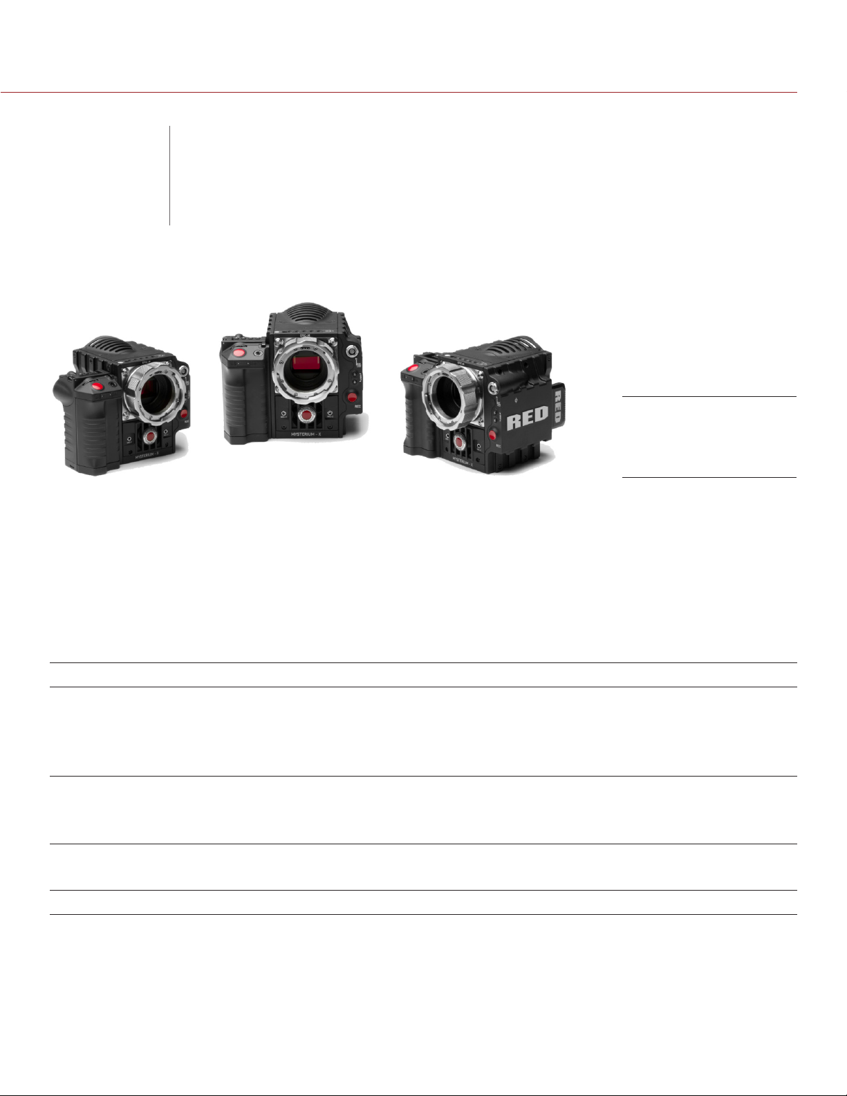
The EPIC and SCARLET cameras are part of the RED® Digital Still and Motion Camera (DSMC®) system. The
DSMC family includes EPIC, SCARLET®, WEAPON, SCARLET-W, and RED RAVEN cameras. With an ultra-high
megapixel count, high frame rate, significant processing power, high dynamic range, and the advantages of a
raw file format, each camera offers the ability to simultaneously capture video and stills.
This guide is for EPIC and SCARLET only. This section introduces the imaging capabilities and advanced
features of the EPIC and SCARLET system. For information about camera systems, see the following operation
guide:
WEAPON/SCARLET-W Operation Guide, available at www.red.com/downloads.
The EPIC and SCARLET system includes the following cameras (organized by sensor type):
INTRODUCTION
EPIC Digital Still
and Motion Cameras
(DSMC)
SENSOR TYPE CAMERA
®
RED DRAGON
MYSTERIUM-X® EPIC-M MYSTERIUM-X
Monochrome EPIC-M Monochrome
RED DRAGON Monochrome EPIC-M RED DRAGON Monochrome
COPYRIGHT © 2016 RED.COM, INC
EPIC-M RED DRAGON (Carbon Fiber)
EPIC-M RED DRAGON
EPIC-X RED DRAGON
SCARLET DRAGON
EPIC-X MYSTERIUM-X
SCARLET-X® MYSTERIUM-X
EPIC-X Monochrome
®
955-0020_V6.2, REV-J | 8
Page 9

EPIC/SCARLET OPERATION GUIDE
READ BEFORE YOU SHOOT
Read this operation guide carefully and in its entirety before assembling or operating your camera or other RED
accessories. In addition to this document, RED offers the following operation guides for the camera system:
DSMC Power Operation Guide
DSMC Media Operation Guide
To download RED operation guides, visit the RED downloads page at www.red.com/downloads.
R3D FILE FORMAT AND REDCODE
All videos and frames are recorded to the R3D® file format. The R3D file format was developed by RED to
provide an efficient and manageable RAW video data format that promotes advanced post production editing
capabilities. In the R3D file format, the digital image received from the sensor is formatted as a pixel-defect
corrected (but in all other aspects unprocessed) 16-bit per pixel RAW data frame. Each RAW frame, or sequence
of RAW frames in a clip, is compressed using a proprietary wavelet based REDCODE® RAW compression, then
stored to a RED MINI-MAG® or REDMAG™ 1.8" SSD.
RAW data is recorded independently of any RGB domain color processing such as ISO, White Balance, or
other RGB color space settings. Instead, color parameters are saved as reference metadata; that is, color is
not burned into the recorded RAW data. This recording technique promotes flexibility in RGB color processing,
which can be deferred to post production or adjusted in the field, without affecting the recorded RAW data
image quality or dynamic range.
REDCODE is a visually lossless, wavelet-based compression codec that reduces R3D RAW files into a
manageable size, allowing longer recording times on media. The ability to compress RAW data is one of the
significant technologies that RED has brought to the industry.
For more information, see the DSMC Media Operation Guide, available at www.red.com/downloads.
NOTE: REDCINE-X PRO® can create and export .RMD “Look” files which may then be imported as camera
monitor path color processing presets. This information is stored as reference metadata, so that these color
processing choices can be the default values used in post production. For more information, go to “Looks” on
page 111.
SHOOT FOR VIDEO AND STILLS
High resolution video, such as the digital footage captured by the camera, has surpassed the detail necessary
to produce professional full-sized prints. Because of the ability to record at high frame rates and resolution, the
camera is ideally suited to capture video and still images, simultaneously.
The camera is equipped with a Stills mode that makes it easier to capture stunning images. With presets
optimized for stills and Swipe-Up Shortcuts for the RED Touch display, switching from Motion mode to Stills
mode is seamless. Using REDCINE-X PRO, or other editing applications supporting the RED SDK, you can pull
full resolution still images from R3D files.
NOTE: Stills mode is compatible with v6.0 firmware or later.
COPYRIGHT © 2016 RED.COM, INC 955-0020_V6.2, REV-J | 9
Page 10
EPIC/SCARLET OPERATION GUIDE
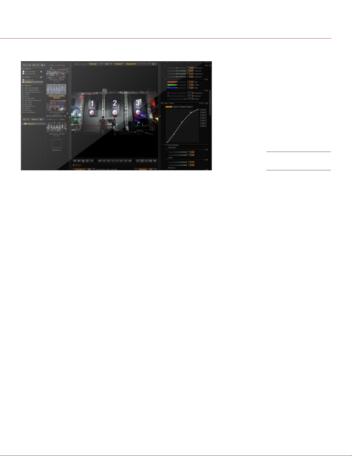
POST PRODUCTION WITH REDCINE-X PRO
REDCINE-X PRO
REDCINE-X PRO is a professional one-light coloring toolset, equipped with an integrated timeline and a post
effects software collection that provides the ideal environment to review recorded footage, edit metadata,
organize projects, and prepare your R3D files. Use either REDCINE-X PRO or a compatible third-party nonlinear editing (NLE) application to edit R3D files. For more information, see the REDCINE-X PRO Operation
Guide, available at www.red.com/downloads.
RED TETHER, included in REDCINE-X PRO, allows you to record footage from your camera directly to a
computer or an external drive. Using tethering bypasses the need to record to an SSD and offload to a
computer later, saving you time.
The latest version of REDCINE-X PRO is available for download at www.red.com/downloads.
NOTE: RED TETHER is included in REDCINE-X PRO build 35 or later.
HDRX AND MAGIC MOTION
HDRX
HDRx extends dynamic range up to six (6) stops by simultaneously capturing two (2) images of identical resolution
and frame rate. The first image is a normally exposed track (A-track), while the second is an underexposed
track (X-track) with an exposure value that reflects the additional stops of highlight protection. These tracks are
“motion-conjoined” during recording, leaving no time gap between the two (2) exposures. This is different from
traditional alternating exposures, which have small gaps between tracks, producing unwanted motion tracks.
MAGIC MOTION
MAGIC MOTION is a post production method that combines two (2) HDRx tracks to create an image with both
natural motion blur (from the A-track) and sharper reference (the X-track). MAGIC MOTION produces an image
with an extraordinary dynamic range that is not available with any other motion capture camera.
Shooting at 24 fps with a 180° (1/48 sec) shutter on traditional film or digital cameras produces motion blur
throughout, which is not the way the human eye observes motion. For example, ask someone to swing their
arm. What you would observe in a traditional recording of this action is constant motion blur until the arm stops.
However, what your eye sees is both motion blur and a sharper reference of the arm throughout the motion
path. MAGIC MOTION creates an image that matches the natural motion observed by the human eye.
COPYRIGHT © 2016 RED.COM, INC
955-0020_V6.2, REV-J | 10
Page 11

EPIC/SCARLET OPERATION GUIDE
ADDITIONAL RESOURCES
The following resources offer additional information about RED, the camera system, and the RED community:
RED.com: Check the official RED website for the latest information about RED products.
RED Learn Articles: RED offers in-depth technical articles about RED cameras, post production, and digital
cinematography.
RED.com/downloads: Go to the RED Downloads page to download the latest firmware, operation guides,
and post production software.
DSMC Toolkit: Go to the RED Downloads page to find the DSMC Toolkit, which offers many helpful tools and
resources to customize and improve your camera workflow.
Support.red.com: Check the RED SUPPORT site for FAQs, or to file a support ticket.
Bomb Squad Support: For more information, contact your Bomb Squad representative.
In-Camera Help: Select the Help button on an in-camera screen to open up the help for that screen.
Reduser.net: Discuss all things RED on the REDUSER third-party forum.
COPYRIGHT © 2016 RED.COM, INC 955-0020_V6.2, REV-J | 11
Page 12
EPIC/SCARLET OPERATION GUIDE
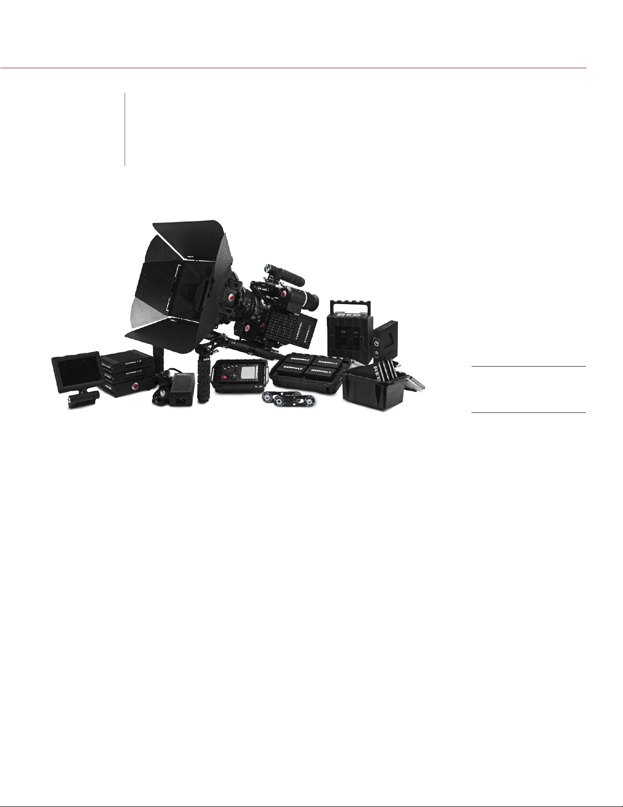
CAMERA SYSTEM
02
This section provides an overview of the camera system components, including:
“BRAIN” on page 13
“Media Modules” on page 14
“REDMAG and RED MINI-MAG Systems” on page 16
“Adaptor Modules” on page 17
“RED Batteries and Chargers” on page 20
“Other Modules” on page 20
“Displays and Electronic Viewfinders” on page 22
“LEMO Adaptors” on page 26
“Camera Control Modules” on page 27
“Lens Mounts” on page 30
“Interchangeable OLPFs” on page 31
“Rails, Mounts, Tactical Gear, and Cables” on page 31
WARNING: Modules and lens mounts are NOT HOT SWAPPABLE, meaning you cannot remove or install these
items while the camera is turned on. Before installing or removing these items, you MUST turn off the camera.
Failure to do so may result in damage to the item or camera that is not covered under warranty.
NOTE: Availability of components listed in this chapter is subject to change at any time.
COMPONENTS
EPIC-M RED
DRAGON Kit
ADDITIONAL RESOURCES
For more information on power and media, see the following guides, available at www.red.com/downloads:
DSMC Power Operation Guide
DSMC Media Operation Guide
COPYRIGHT © 2016 RED.COM, INC
955-0020_V6.2, REV-J | 12
Page 13
EPIC/SCARLET OPERATION GUIDE
BRAIN
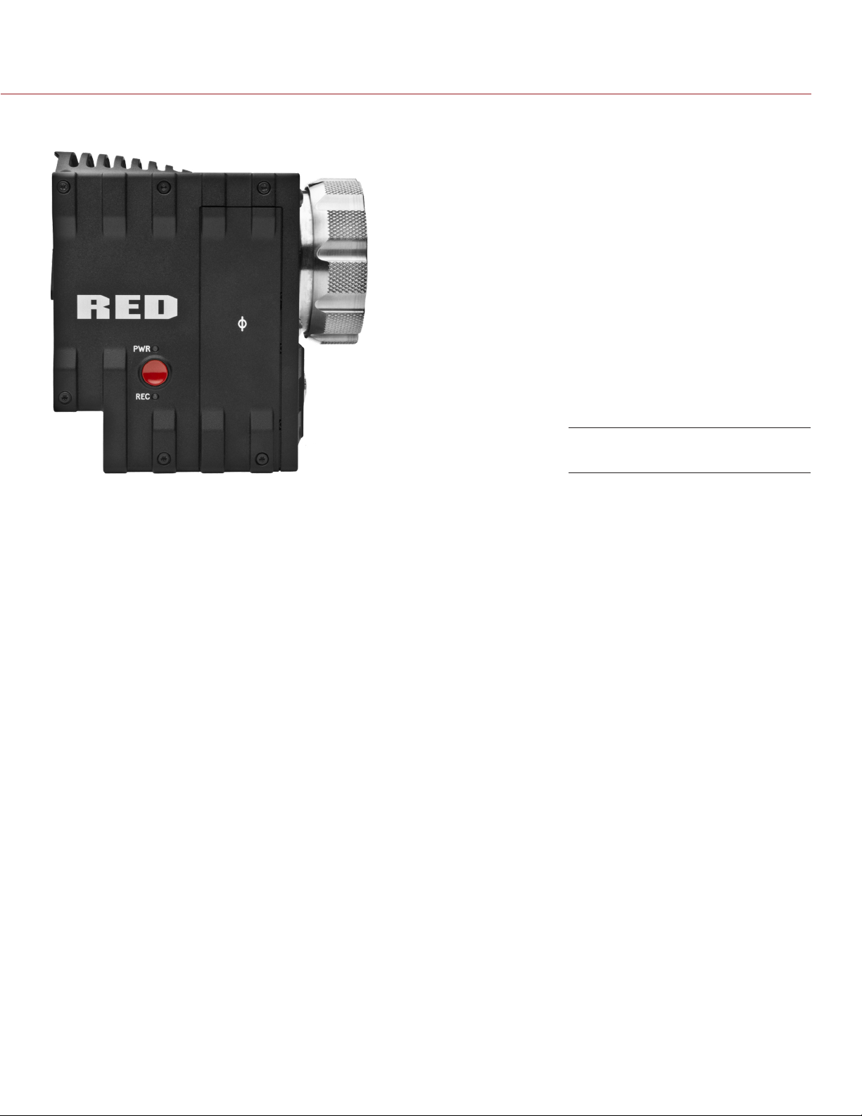
EPIC BRAIN (Side)
The DSMC BRAIN® is the image processing center of the camera system and supports power, media, and other
modules.
BRAIN CONTROL: PWR/REC KEY
Fully press and hold the PWR/REC key for two (2) seconds to turn on/off.
When the camera is on, fully press and then release the PWR/REC key to toggle record start/stop.
COPYRIGHT © 2016 RED.COM, INC 955-0020_V6.2, REV-J | 13
Page 14

EPIC/SCARLET OPERATION GUIDE
BRAIN LEDS
This section describes the LED functions for the camera.
LED COLOR/FLASHING DESCRIPTION
Power Status LED
(PWR)
Record Status LED
(REC)
Power Status LED (PWR)
and Record Status LED (REC)
Off No power present
Green Power present; camera on
Amber flashing Power present; 5–10 min of battery time
available
Amber Power present; camera booting
Red flashing Power present; ≤ 5 min of battery time
available
Red Power present; camera off
Off No media present
Green Ready to record
Amber Finalizing
Red flashing (slow) Media mounted with > 5% and ≤ 10% of media
space available
Red flashing (fast) Media mounted with 5% of media space
available
Red Recording
Both green flashing Firmware update in progress
Both red flashing Firmware update error
MEDIA MODULES
This section describes the media modules. RED offers the following media modules:
ITEM PART NUMBER
DSMC 1.8" SSD Side Module 720-0013
DSMC 1.8" SSD Side Module (DRAGON)
Carbon Fiber DSMC 1.8" SSD Side Module (DRAGON)
®
RED MINI-MAG
Carbon Fiber RED MINI-MAG Side SSD Module
Rear SSD Module 720-0009
1. The DSMC 1.8" SSD Side Module (DRAGON) is only available with the purchase of a RED DRAGON sensor-based BRAIN.
2. Carbon fiber side SSD modules are only available with the purchase of a carbon fiber BRAIN.
Side SSD Module 720-0021
1
2
2
N/A
N/A
N/A
COPYRIGHT © 2016 RED.COM, INC
955-0020_V6.2, REV-J | 14
Page 15
EPIC/SCARLET OPERATION GUIDE
SIDE SSD MODULES
RED MINI-MAG Side SSD
Module
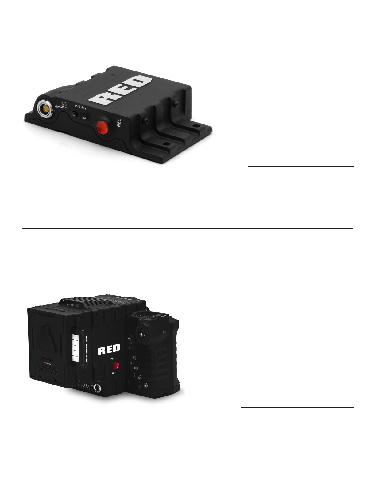
Media modules attach to the camera to enable the use of RED MINI-MAG or REDMAG™ 1.8" SSD media. Both
side SSD module systems have the same EVF/LCD LEMO® connector, user keys, and REC button.
For more information, see the DSMC Media Operation Guide, available at www.red.com/downloads.
SIDE SSD MODULE CONNECTOR
CONNECTOR CONNECTOR TYPE CONNECTOR FUNCTION
EVF/LCD N/A Power and external monitoring support for an electronic
viewfinder or display
SIDE SSD MODULE CONTROLS
REAR SSD MODULE
Rear SSD Module
The Rear SSD Module secures to the back of a Module Adaptor or a +1 Adaptor Module to serve as a rear
location for recording to a REDMAG 1.8" SSD.
For more information, see the DSMC Media Operation Guide, available at www.red.com/downloads.
COPYRIGHT © 2016 RED.COM, INC 955-0020_V6.2, REV-J | 15
Page 16
EPIC/SCARLET OPERATION GUIDE
REDMAG AND RED MINI-MAG SYSTEMS
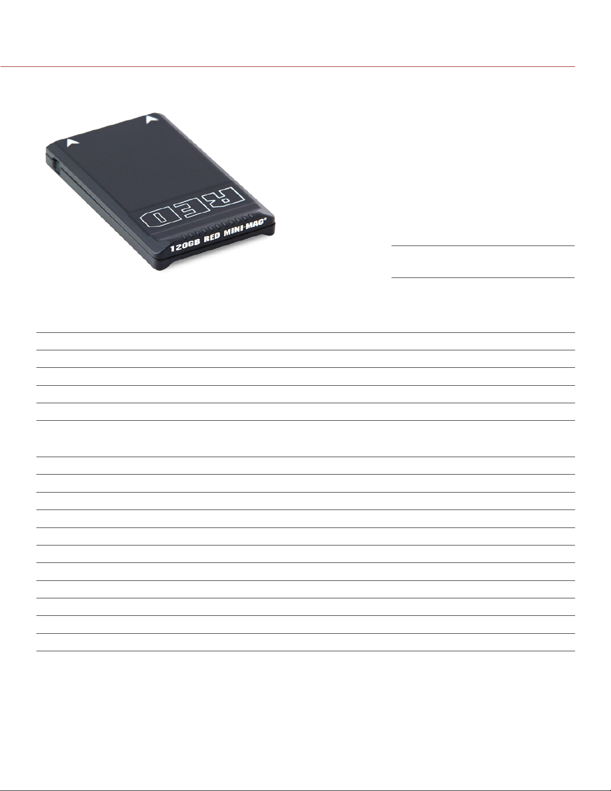
RED MINI-MAG (120GB)
REDMAG 1.8" SSDs and RED MINI-MAG® SSDs deliver fast and reliable recording options for your camera. A
RED STATION® enables you to connect media to your computer for offloading and editing.
RED offers the following RED MINI-MAG SSDs:
ITEM PART NUMBER REQUIRED FIRMWARE
RED MINI-MAG (120GB) 750-0075 v5.3.47 or later; or v6.0.40 or later
RED MINI-MAG (240GB) 725-0082 v5.1.47 or later
RED MINI-MAG (512GB) 725-0078 v5.1.34 or later
1
RED MINI-MAG (1TB)
1. The RED MINI-MAG 1TB can take up to 20 seconds to mount to a computer or a camera.
725-0081 v5.3.34 or later
RED offers the following REDMAG 1.8" SSDs and compatible RED STATIONS:
ITEM PART NUMBER
REDMAG 1.8" SSD (48GB) 750-0044
REDMAG 1.8" SSD (64GB) 750-0025
REDMAG 1.8" SSD (128GB)
REDMAG 1.8" SSD (240GB)
REDMAG 1.8" SSD (256GB)
REDMAG 1.8" SSD (512GB)
1
2
1
1
750-0021
750-0061
750-0026
750-0037
RED STATION REDMAG 1.8" 750-0006
RED STATION REDMAG 1.8" (MINI)–ESATA 750-0035
RED STATION REDMAG 1.8" (MINI)–USB 3.0 750-0036
RED STATION REDMAG 2.5" 750-0007
1. These REDMAG 1.8" SSDs are no longer available for purchase at red.com, but are still supported by RED.
2. The REDMAG 1.8" SSD (240GB) requires that your camera is on firmware v5.1.44 or later.
For more information, see the DSMC Media Operation Guide, available at www.red.com/downloads.
COPYRIGHT © 2016 RED.COM, INC
955-0020_V6.2, REV-J | 16
Page 17
EPIC/SCARLET OPERATION GUIDE
ADAPTOR MODULES
This section describes the adaptor modules.
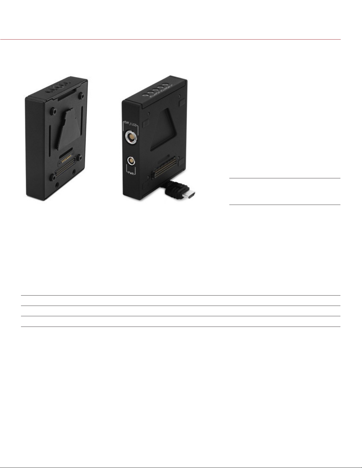
Module Adaptor (left) and
+1 Adaptor Module (right)
Adaptor modules enable you to connect other modules to the camera for expandable functionality. The +1
Adaptor Module provides an auxiliary power port for accessories and an additional EVF/LCD port for additional
monitor viewing and output.
Both adaptor modules also offer additional 1/4-20 mounting points on top for configuration support. Most
modules require a Module Adaptor or +1 Adaptor Module to attach to your camera.
For more information, go to “Configure Your Camera” on page 30.
WARNING: The Module Adaptor is NOT compatible with the +1 Adaptor Module.
WARNING: The +1 Adaptor Module IS NOT compatible with the Module Adaptor.
WARNING: DO NOT use the EVF/LCD port if a Pro I/O Module is connected to the camera.
RED offers the following adaptor modules:
ITEM PART NUMBER
Module Adaptor 720-0008
+1 Adaptor Module
1. The +1 Adaptor Module requires that your camera is on firmware v4.08 or later.
1
720-0018
COPYRIGHT © 2016 RED.COM, INC 955-0020_V6.2, REV-J | 17
Page 18
EPIC/SCARLET OPERATION GUIDE
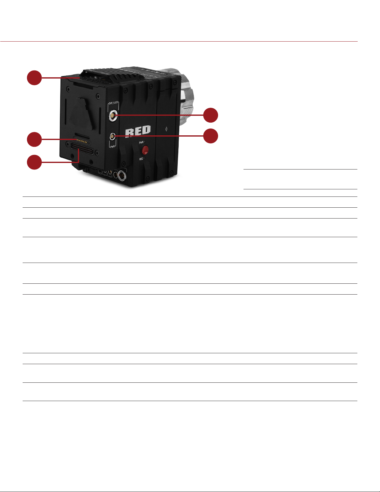
+1 ADAPTOR MODULE CONNECTIONS
1
2
4
3
5
+1 Adaptor Module
# CONNECTOR CONNECTOR TYPE CONNECTOR FUNCTION
1 Mounting 1/4-20 mounting Supports bolt-on auxiliary equipment
2 EVF/LCD
3 Auxiliary power
out (PWR)
4 REDMOTE
connector
5 Dock connector SEARAY connector Supports power and communication with modules
1. WARNING: DO NOT use the EVF/LCD connector if a Pro I/O Module is connected to the camera.
NOTE: The default auxiliary power output setting is on. To toggle the power setting on/off, go to Menu > Power >
Power Out > +1 PWR. The last power output setting is saved until a firmware upgrade or a factory reset.
1
®
dock
N/A Custom digital video and power interconnection between the
camera and RED EVF or RED LCD; Pinout not published
4-pin 0B LEMO Supplies unregulated (+) 11.5 to 17 V battery pass-through;
Connect to 2-pin LEMO accessories with the RED 4-Pin to
2-Pin Adaptor Cable; Max sustained current is 2 A
8-point POGO
connector
Power and support for the REDMOTE
+1 ADAPTOR MODULE ACCESSORIES
For more information, as well as a full list of EVF/LCD cables and other accessory cables, visit www.red.com.
ACCESSORY CONNECTOR TYPE CONNECTOR FUNCTION PART NUMBER
4-Pin To 2-Pin
Adaptor Cable
Micro HDMI-toHDMI Adaptor
1. The 4-Pin to 2-Pin Adaptor Cable converts 4-pin power into a 2-pin female LEMO connection, enabling support for 2-pin based accessories from the +1 Adaptor Module or Pro I/O Module.
2. The Micro HDMI-to-HDMI Adaptor is field-replaceable.
COPYRIGHT © 2016 RED.COM, INC
4-pin 0B to 2-pin 0B
1
LEMO
Micro HDMI to
2
Standard HDMI
Power support for 2-pin based accessories 790-0334
HDMI video connection from the camera to
support auxiliary EVF/LCD attachment
955-0020_V6.2, REV-J | 18
N/A
Page 19
EPIC/SCARLET OPERATION GUIDE
POWER MODULES
This section describes the power modules for the camera.
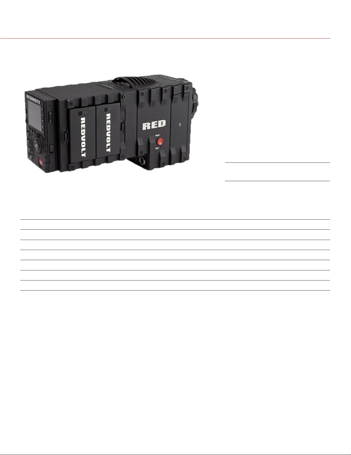
Pro Battery Module (Quad)
Power modules attach to a Module Adaptor or +1 Adaptor Module to provide the camera with flexible power
options for REDVOLT®, REDVOLT XL, and RED BRICK® batteries. When used in combination with a DSMC AC
Power Adaptor or DSMC Side Handle, you can hot-swap batteries without interrupting recording.
RED offers the following power modules:
ITEM PART NUMBER
Pro Battery Module (Dual) 720-0005
Pro Battery Module (Quad) 720-0006
REDVOLT XL Module
Quickplate Module 790-0343
Backpack Quickplate (Short) 790-0342
RED Quickplate 790-0008
1. The REDVOLT XL Module requires that your camera is on firmware v5.1.29 or later.
For more information, see the DSMC Power Operation Guide, available at www.red.com/downloads.
1
740-0031
COPYRIGHT © 2016 RED.COM, INC 955-0020_V6.2, REV-J | 19
Page 20
EPIC/SCARLET OPERATION GUIDE
RED BATTERIES AND CHARGERS
This section describes the RED lithium-ion batteries and charger solutions.
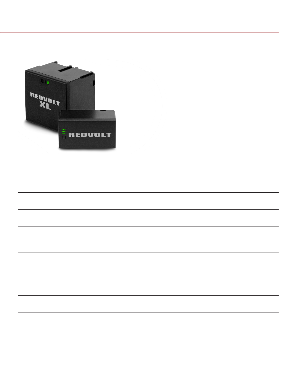
REDVOLT XL (left) and REDVOLT
(right)
The REDVOLT, REDVOLT XL, and RED BRICK are lightweight, rechargeable lithium-ion battery cells that provide
sustained power to the camera. These batteries provide long-term mobile power and attach to the camera via
a power module or other RED accessory, such as the DSMC Side Handle. RED chargers replenish lost capacity
for REDVOLT, REDVOLT XL, and RED BRICK batteries.
RED offers the following batteries and chargers:
ITEM PART NUMBER
REDVOLT 740-0020
REDVOLT XL 740-0021
RED BRICK 740-0002
REDVOLT Travel Charger 790-0134
REDVOLT Charger (Quad) 740-0015
RED CHARGER 740-0006
For more information, see the DSMC Power Operation Guide, available at www.red.com/downloads.
OTHER MODULES
This section describes other modules. RED offers the following miscellaneous modules:
ITEM PART NUMBER
Pro I/O Module 720-0004
REDCAST Module
1. The REDCAST Module requires that your camera is on firmware v5.2.28 or later.
1
720-0025
COPYRIGHT © 2016 RED.COM, INC
955-0020_V6.2, REV-J | 20
Page 21
EPIC/SCARLET OPERATION GUIDE
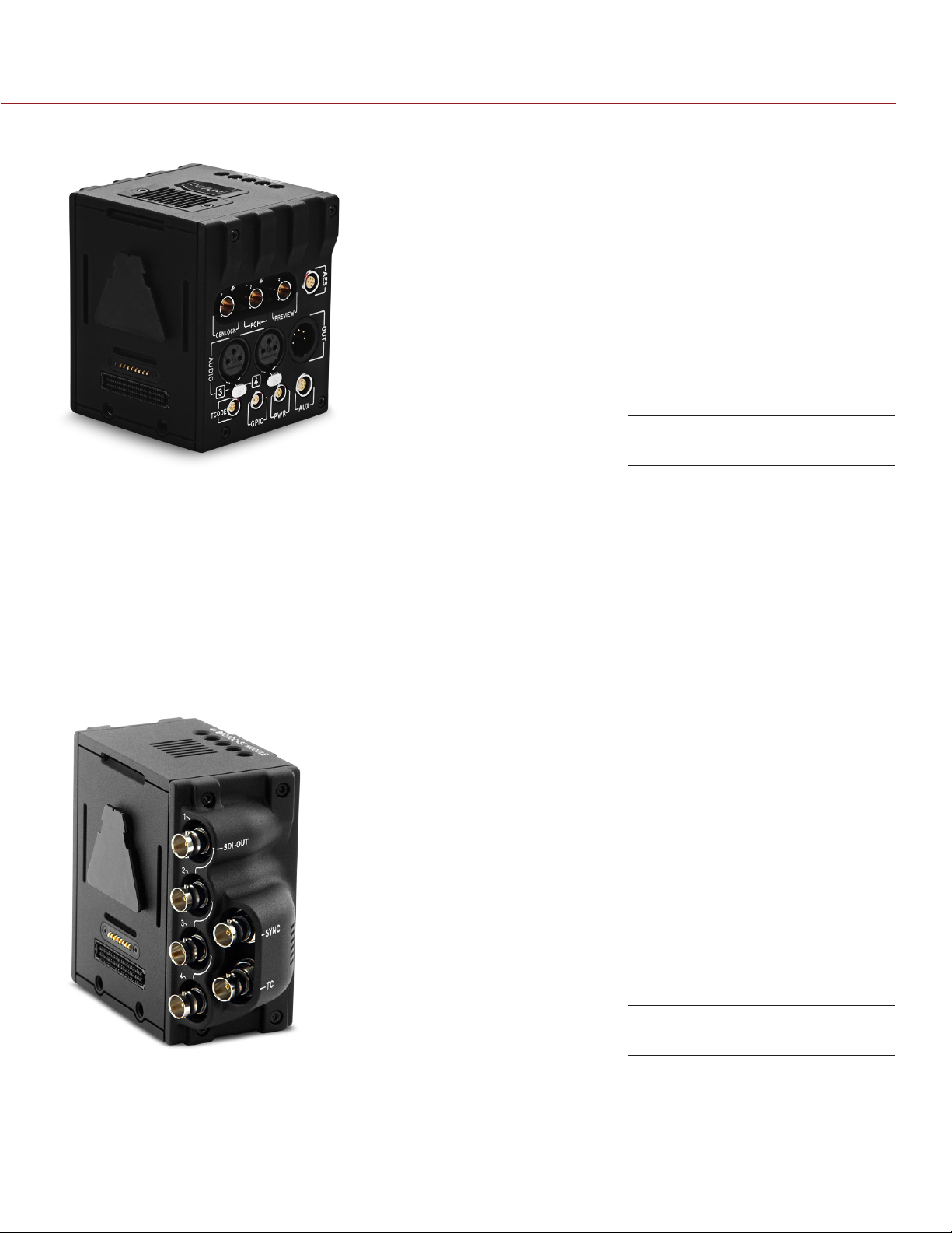
PRO I/O MODULE
Pro I/O Module
The Pro I/O Module brings together the essential input and output (I/O) connections in one (1) module, providing
a central hub for professional audio and video components. The Pro I/O Module offers the following features:
Centralized ports that make it easy to manage connections and cables.
LCD/EVF port that allows you to connect an additional RED LCD or EVF.
Customizable triggers that interface with third-party GPIO and RS232 control devices using Pro I/O cables.
Mounting points for an additional module or a REDMOTE.
Internal cooling system that maintains an appropriate operating temperature.
For more information, see the Pro I/O Module Operation Guide, available at www.red.com/downloads.
REDCAST MODULE
REDCAST Module
The REDCAST™ Module allows for live 4K streaming, enabling you to capture and view action in real-time.
Compatible with both EPIC DRAGON and SCARLET DRAGON cameras, the REDCAST Module uses four (4)
3G-SDI output connections to broadcast 4K video at up to 60 frames per second. Five (5) 1/4-20 mounting
holes are built into the top of the module, allowing for various mechanical peripherals to be attached.
For more information, see the REDCAST Module Operation Guide, available at www.red.com/downloads.
COPYRIGHT © 2016 RED.COM, INC 955-0020_V6.2, REV-J | 21
Page 22
EPIC/SCARLET OPERATION GUIDE
DISPLAYS AND ELECTRONIC VIEWFINDERS
RED offers the following displays and electronic viewfinders (EVFs):
NOTE: RED offers multiple mounting solutions for each camera type.
ITEM RESOLUTION PART NUMBER
DSMC2 RED Touch 7.0" LCD (Woven CF)
DSMC2 RED Touch 7.0” LCD (Aluminum)
DSMC2 RED Touch 4.7" LCD
RED Touch 5.0" LCD
RED Touch 7.0" LCD
RED Touch 9.0" LCD
RED PRO LCD 7"
2
2, 3
2
2
DSMC2 RED EVF (OLED)
®
BOMB EVF
(LCOS)
BOMB EVF (OLED)
1. Using this display with an EPIC or SCARLET camera requires a DSMC2 LEMO Adaptor B.
2. Using this display with a WEAPON, SCARLET-W, or RAVEN camera requires a DSMC2 LEMO Adaptor A.
3. The RED Touch 7.0" LCD requires that your camera is on firmware v5.2.38 or later.
2
2
2
2
1
1
For a full list of LCD and EVF user keys and default actions, go to “Default Key Functions” on page 188.
1920 x 1136 730-0018
1920 x 1136 730-0024
1280 x 720 730-0019
800 x 400 730-0008
1920 x 1136 730-0007
1280 x 768 730-0011
1024 x 600 730-0009
1920 x 1080 730-0021
1280 x 784 730-0004
1280 x 1024 730-0010
RED LCDS
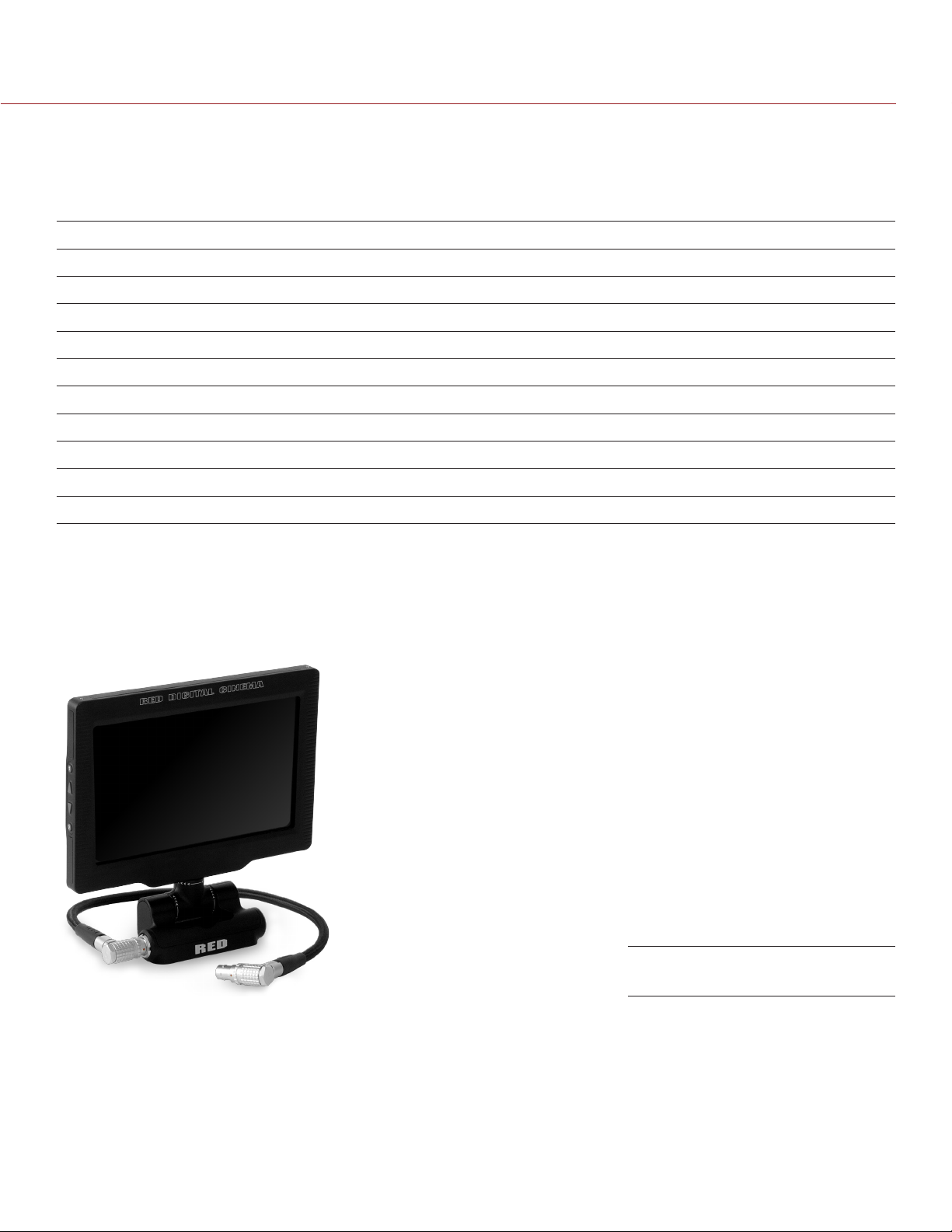
RED Touch 7.0" LCD
RED displays provide important camera parameters on the graphical user interface (GUI) and offer a variety of
monitor viewing options. RED touchscreen displays enable you to use gestures to navigate menus and adjust
camera parameters. RED displays feature 8-bit RGB, 4:4:4 progressive scan, providing up to 16.7 million colors
and up to 70% NTSC color gamut.
LCD PRECAUTIONS
WARNING: DO NOT use a RED display as a handle to lift or carry the camera. Damage to a RED display or other
components of the camera system caused by using the display as a handle are not covered under warranty.
COPYRIGHT © 2016 RED.COM, INC
955-0020_V6.2, REV-J | 22
Page 23

EPIC/SCARLET OPERATION GUIDE
WARNING: DO NOT use the threaded holes in the RED Touch LCD base to mount the display to the camera.
Damage to a RED display or other components of the camera system caused by using these threaded holes
is not covered under warranty.
IMPORTANT: The RED Touch LCD swivel axis has a total adjustment range of approximately 360˚ (180˚ clockwise
or counterclockwise from the nominal “rear-facing” orientation). The tilt axis range of adjustment is approximately
180˚. Damage to a RED display or other camera components caused by excessive force is not covered under
warranty.
IMPORTANT: The DSMC2 RED Touch 4.7" LCD has a tilt axis range of approximately 240˚ (90˚ forward and 150˚
backward). Damage to a RED display or other camera components caused by excessive force is not covered
under warranty.
BOMB EVFS
The BOMB EVF (LCOS) and BOMB EVF (OLED) deliver specialized viewing solutions for the camera. The BOMB
EVF (LCOS) is a high-definition, lightweight, and low-profile viewfinder. The BOMB EVF (OLED) uses OLED
technology, providing deeper blacks and more color accurate images.
ITEM CONTRAST RATIO DIOPTER RANGE
BOMB EVF (LCOS)
BOMB EVF (OLED)
1. Using these displays with a WEAPON, SCARLET-W, or RAVEN camera requires a DSMC2 LEMO Adaptor A.
WARNING: DO NOT point the BOMB EVF (OLED) eyepiece at direct sunlight. Continued exposure to direct
sunlight may damage the EVF. Point the eyepiece away from sunlight when not in use. Damage to the BOMB
EVF (OLED) caused by continued exposure to direct sunlight is not covered under warranty.
1
1
1000:1 typical 2.0 to –5.0.1
>10,000:1 typical 2.0 to –5.0.1
COPYRIGHT © 2016 RED.COM, INC 955-0020_V6.2, REV-J | 23
Page 24
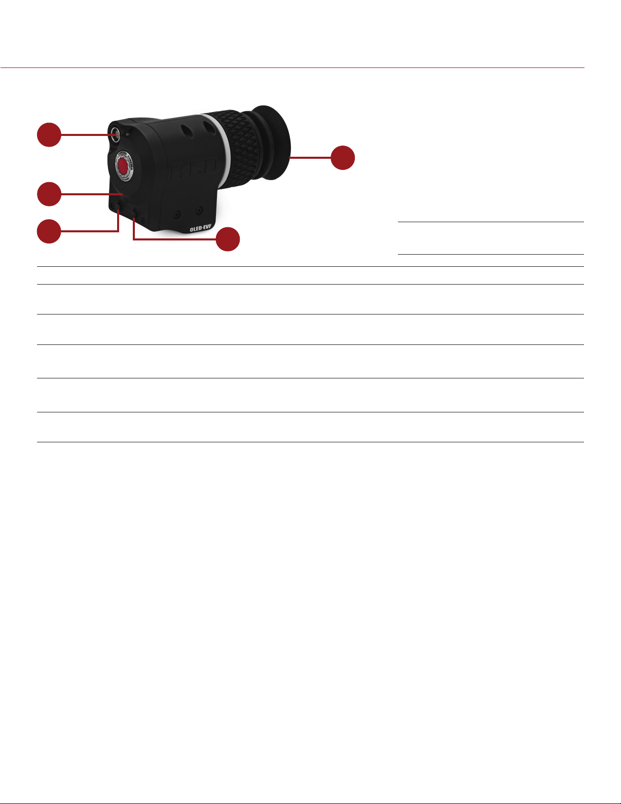
EPIC/SCARLET OPERATION GUIDE
BOMB EVF FEATURES
1
5
2
3
# FEATURE DESCRIPTION
1 EVF connector Custom digital video and power interconnection between the camera and
RED EVF; Pinout not published
2 EVF Tally LED When enabled, the LED illuminates red when recording; For more information,
go to “Indicator” on page 80
3 Key 1 Programmable key
Magnify: Toggle
4 Key 2 Programmable key
Exposure Check: Toggle
5 Eyepiece heater The integrated eyepiece heater automatically heats the eyepiece when the
EVF detects a low ambient temperature
4
BOMB EVF (OLED)
DSMC2 RED EVF
The DSMC2 RED EVF (OLED) is a high definition electronic viewfinder designed as the ideal single-viewer
monitoring solution. Featuring the latest OLED technology, this EVF provides an unmatched personal viewing
experience with a 1080p OLED micro-display, and improved color accuracy with 30-bit RGB color represenation.
View and monitor your RED footage as it is intended with truer colors and deeper blacks in a larger field of view.
Engineered with OBSOLESCENCE OBSOLETE® in mind, the DSMC2 RED EVF (OLED) is perfect for use with
WEAPON, SCARLET-W, RAVEN, EPIC, or SCARLET cameras. RED offers multiple mounting solutions for each
camera type.
WARNING: DO NOT point the DSMC2 RED EVF (OLED) eyepiece at direct sunlight. Continued exposure to direct
sunlight may damage the EVF. Point the eyepiece away from sunlight when not in use. Damage to the DSMC2
RED EVF (OLED) caused by continued exposure to direct sunlight is not covered under warranty.
COPYRIGHT © 2016 RED.COM, INC
955-0020_V6.2, REV-J | 24
Page 25
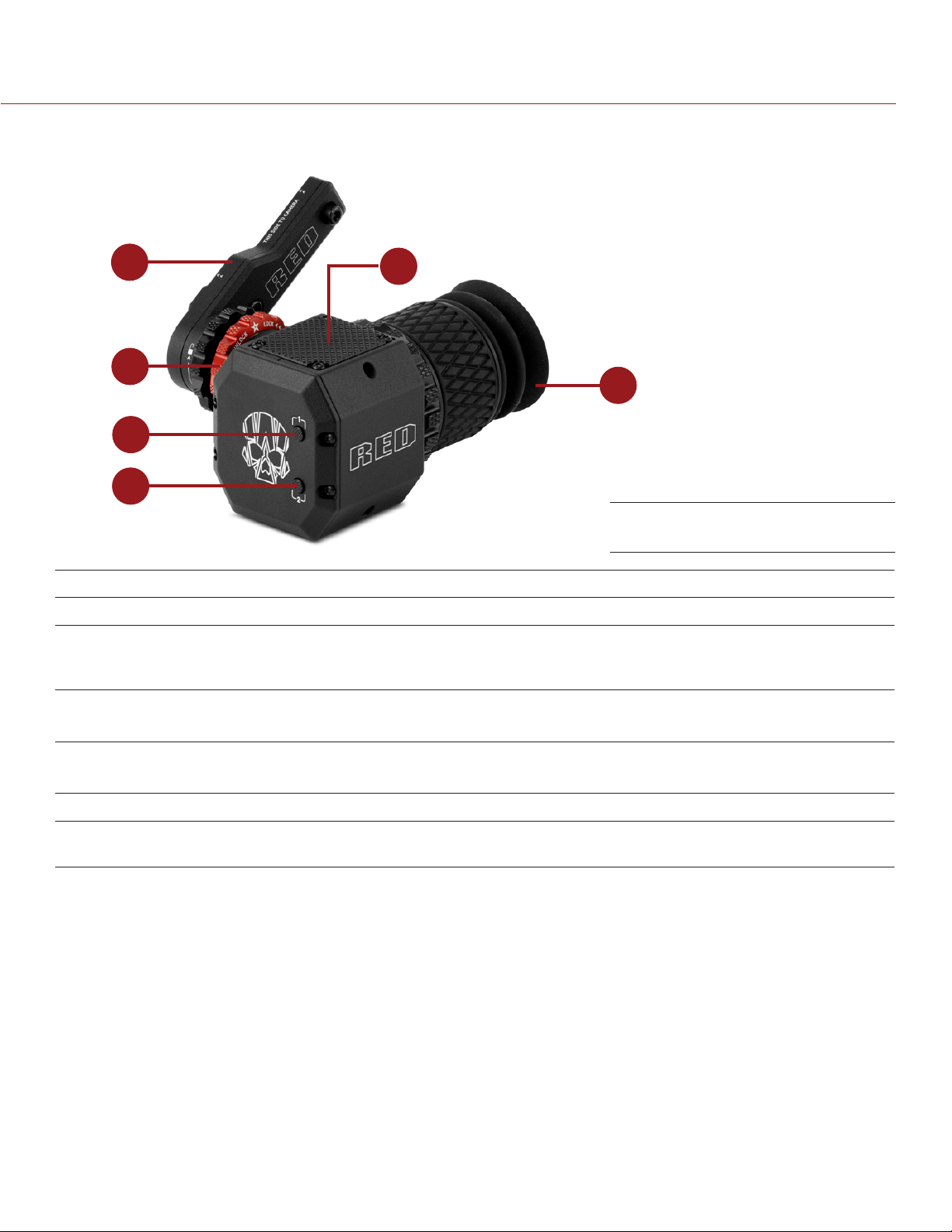
EPIC/SCARLET OPERATION GUIDE
DSMC2 RED EVF FEATURES
1
5
2
3
4
# FEATURE DESCRIPTION
1 DSMC2 RED EVF Mount The DSMC2 RED EVF Mount
2 EVF connector
3 Key 1 Programmable key
1
Custom digital video and power interconnection between the EVF and
other RED devices; Pinout not published; compatible with standard RED
EVF/LCD LEMO cables
Magnify: Toggle
6
DSMC2 RED EVF
4 Key 2 Programmable key
Exposure Check: Toggle
5 Mounting point Mounting point for the DSMC2 RED EVF Mounting Plate (Top)
6 DSMC2 RED EVF
Modular Optical Block
1. Not visible. Shown with the DSMC2 RED EVF Mount attached.
COPYRIGHT © 2016 RED.COM, INC 955-0020_V6.2, REV-J | 25
Fully coated with a > 32° field of view
Page 26
EPIC/SCARLET OPERATION GUIDE
LEMO ADAPTORS
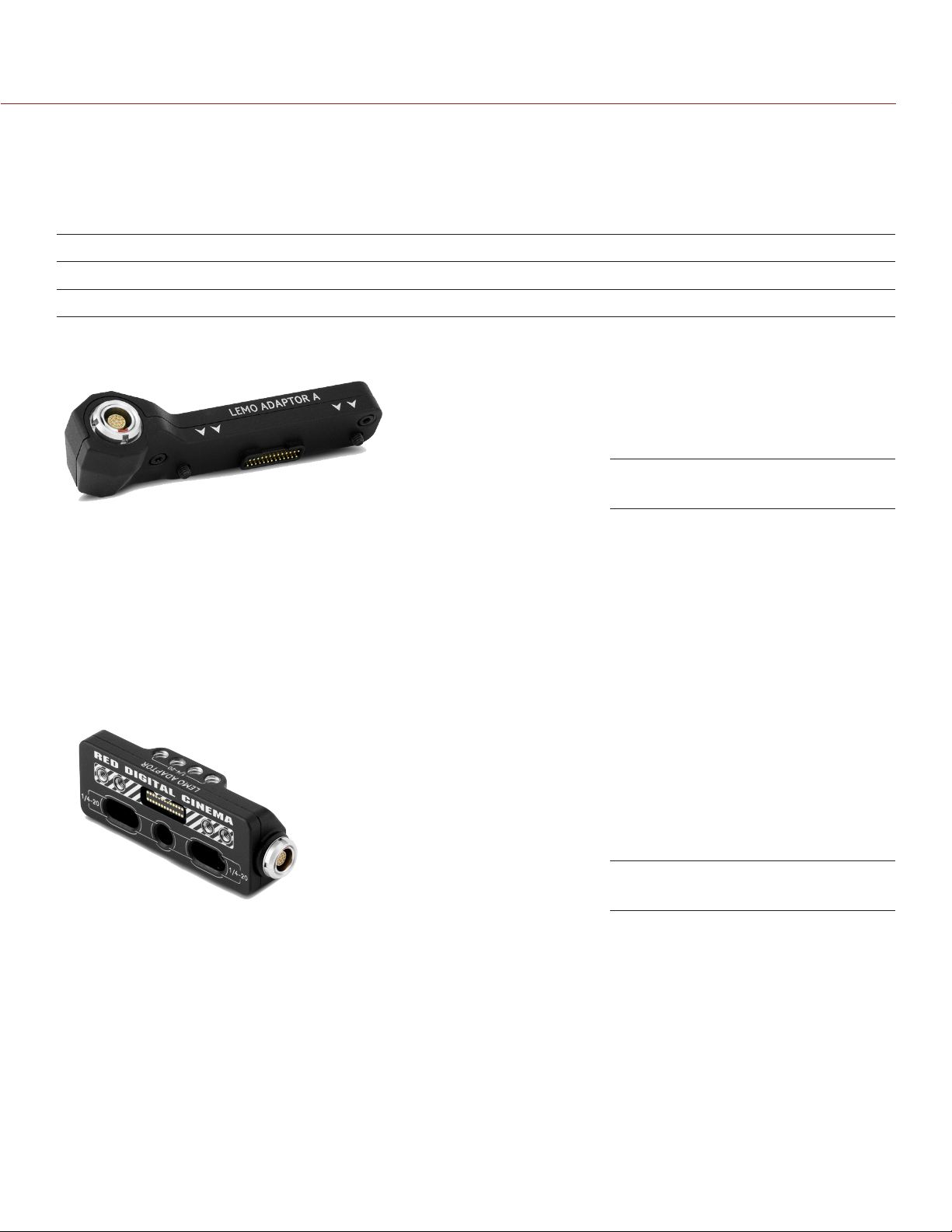
This section describes the DSMC2 LEMO Adaptor A and the DSMC2 LEMO Adaptor B. These adaptors enable
you to use EPIC/SCARLET displays with your DSMC2 camera and use DSMC2 displays with your EPIC/SCARLET
camera. For more information on available displays, go to “Displays and Electronic Viewfinders” on page 22.
ITEM PART NUMBER
DSMC2 LEMO Adaptor A 720-0037
DSMC2 LEMO Adaptor B 720-0038
LEMO ADAPTOR A
DSMC2 LEMO Adaptor A
The DSMC2 LEMO Adaptor A makes your existing RED Touch and RED PRO displays, as well as RED EVFs,
fully compatible with the DSMC2 camera system. The DSMC2 LEMO Adaptor A converts the pogo connection
on the DSMC2 camera to a legacy EVF/LCD LEMO port. The DSMC2 LEMO Adaptor A is designed to attach to
the primary (top), or the secondary (side) EVF/LCD port on the DSMC2 camera.
When used along with the DSMC2 LEMO Adaptor B, this adaptor enables you to mount a DSMC2 RED Touch
LCD away from the camera—to a NOGA arm or other stable mounting point.
The DSMC2 LEMO Adaptor A is compatible with the BOMB EVF, (LCOS) and (OLED) models, or later.
LEMO ADAPTOR B
DSMC2 LEMO Adaptor B
The DSMC2 LEMO Adaptor B enables you to use a DSMC2 RED Touch LCD with your existing EPIC or SCARLET
camera. The DSMC2 LEMO Adaptor B converts the display signal from a pogo connection to a legacy EVF/
LCD LEMO port. The DSMC2 LEMO Adaptor B is designed to mount to your EPIC or SCARLET camera using
standard 1/4-20 mounting holes.
When used along with the DSMC2 LEMO Adaptor A, this adaptor enables you to mount a DSMC2 RED Touch
LCD away from the camera—to a NOGA arm or other stable mounting point.
COPYRIGHT © 2016 RED.COM, INC
955-0020_V6.2, REV-J | 26
Page 27
EPIC/SCARLET OPERATION GUIDE
CAMERA CONTROL MODULES
This section describes the camera control modules. These devices provide a wide array of programmable
buttons, controls, and other features to interact with the camera.
RED offers the following remotes and controls:
ITEM PART NUMBER
DSMC Side Handle 720-0012
RED Switchblade-M
REDMOTE 770-0006
®
REDLINK
1. The RED Switchblade-M requires that your camera is on firmware v5.2.28 or later. Full functionality requires firmware v5.3 or later.
2. The REDLINK Bridge requires that your camera is on firmware v5.2.28 or later.
Bridge (REDLINK Development Kit) 720-0028
1
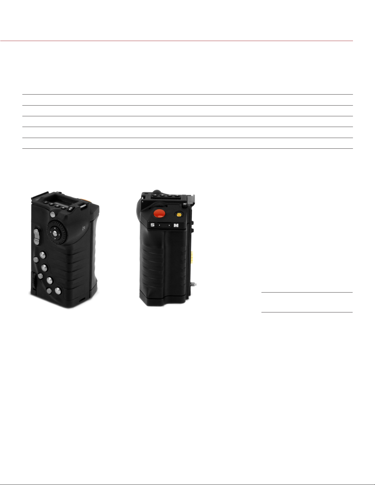
DSMC SIDE HANDLE
720-0026
DSMC Side Handle
The DSMC Side Handle provides programmable menu controls and a battery compartment that holds one (1)
REDVOLT battery. The DSMC Side Handle LCD display shows camera parameter values and illuminates for
operation in dark environments. When a REDVOLT is installed in the DSMC Side Handle, batteries connected
to other power modules may be hot-swapped, providing uninterrupted operation.
For a full list of DSMC Side Handle user keys and default actions, go to “Default Key Functions” on page 188.
NOTE: Upgrading your camera to v5.3 also upgrades the DSMC Side Handle. During the upgrade, you will be
instructed to shut down the camera twice so that the firmware upgrades successfully. Any DSMC Side Handle
that is upgraded to v5.3 can only be used with cameras running v5.2 or later. To use a DSMC Side Handle with
v5.1 after you have upgraded it to v5.3, first downgrade to v5.2, and then downgrade to v5.1.
COPYRIGHT © 2016 RED.COM, INC 955-0020_V6.2, REV-J | 27
Page 28
EPIC/SCARLET OPERATION GUIDE
RED SWITCHBLADE-M
RED Switchblade-M
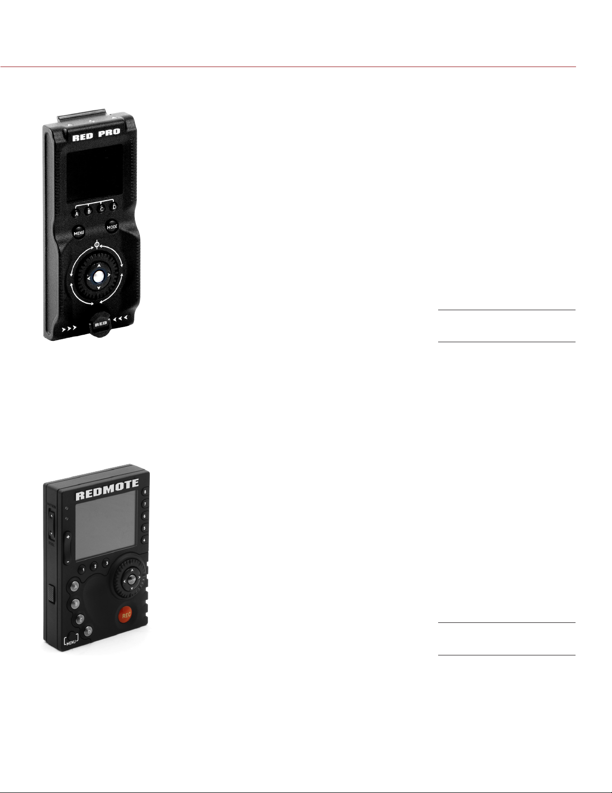
The RED Switchblade-M is a low-profile and lightweight interface solution that mounts to the side of the
camera. With a 1.7” OLED display and full navigation controls, the RED Switchblade-M grants full access to
menus while optimizing the size and weight of y our camera configuration.
For a full list of RED Switchblade-M user keys and default actions, go to “Default Key Functions” on page 188.
NOTE: The RED Switchblade-M requires camera firmware v5.2.28 or later. Full functionality requires camera
firmware v5.3 or later.
REDMOTE
REDMOTE
The REDMOTE is a remote camera control unit that attaches to the rear of the camera or rearmost expansion
module. The REDMOTE may be detached from the camera or rearmost module and provide wireless remote
control of the camera over the proprietary REDLINK protocol.
For a full list of REDMOTE user keys and default actions, go to “Default Key Functions” on page 188.
For more information, go to “REDMOTE Operation” on page 146.
IMPORTANT: To operate properly, upgrade both REDMOTE and camera firmware to the most recent version.
COPYRIGHT © 2016 RED.COM, INC
955-0020_V6.2, REV-J | 28
Page 29
EPIC/SCARLET OPERATION GUIDE
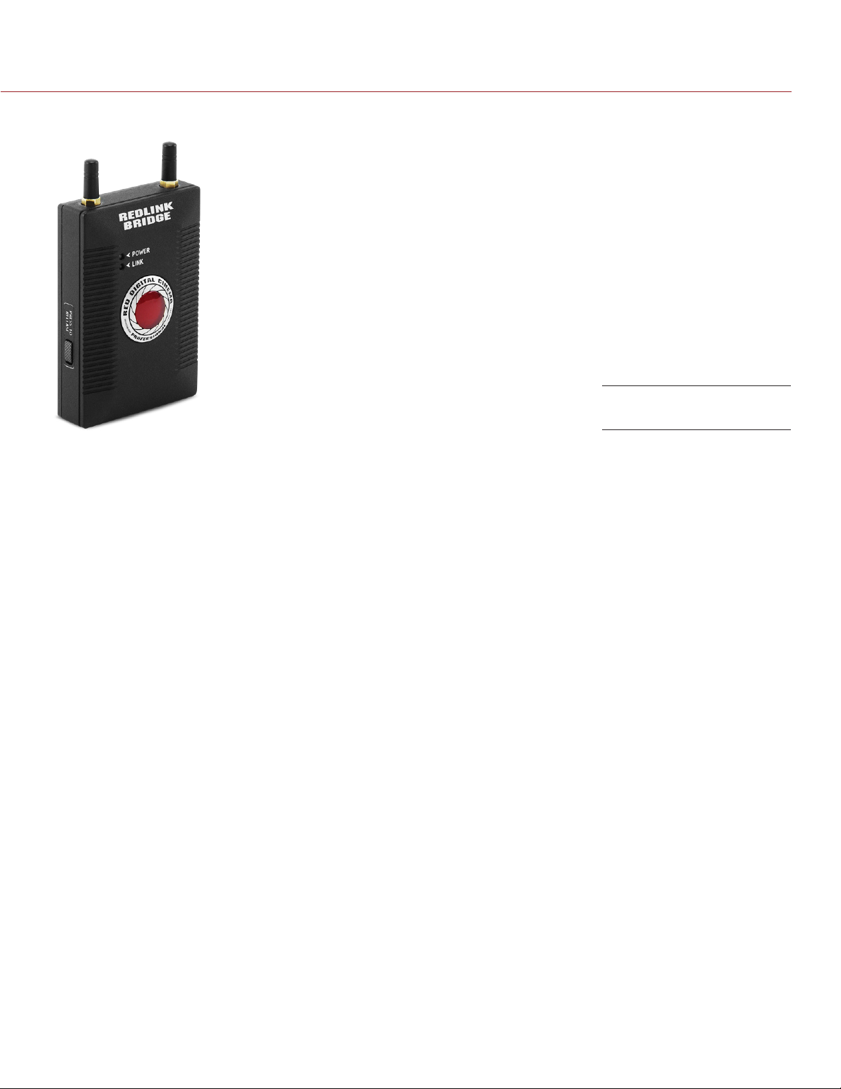
REDLINK BRIDGE
REDLINK Bridge
The REDLINK Bridge is a wireless module that provides communication support for third-party app development.
The REDLINK Bridge attaches to the rear of the camera or other compatible rear module. The REDLINK Bridge
is part of the REDLINK Development Kit and uses the REDLINK Command Protocol (RCP) to communicate
information between the camera and your application.
For more information, see the REDLINK Bridge Operation Guide, available at www.red.com/downloads.
NOTE: The REDLINK Bridge requires camera firmware v5.2.8 or later.
COPYRIGHT © 2016 RED.COM, INC 955-0020_V6.2, REV-J | 29
Page 30
EPIC/SCARLET OPERATION GUIDE
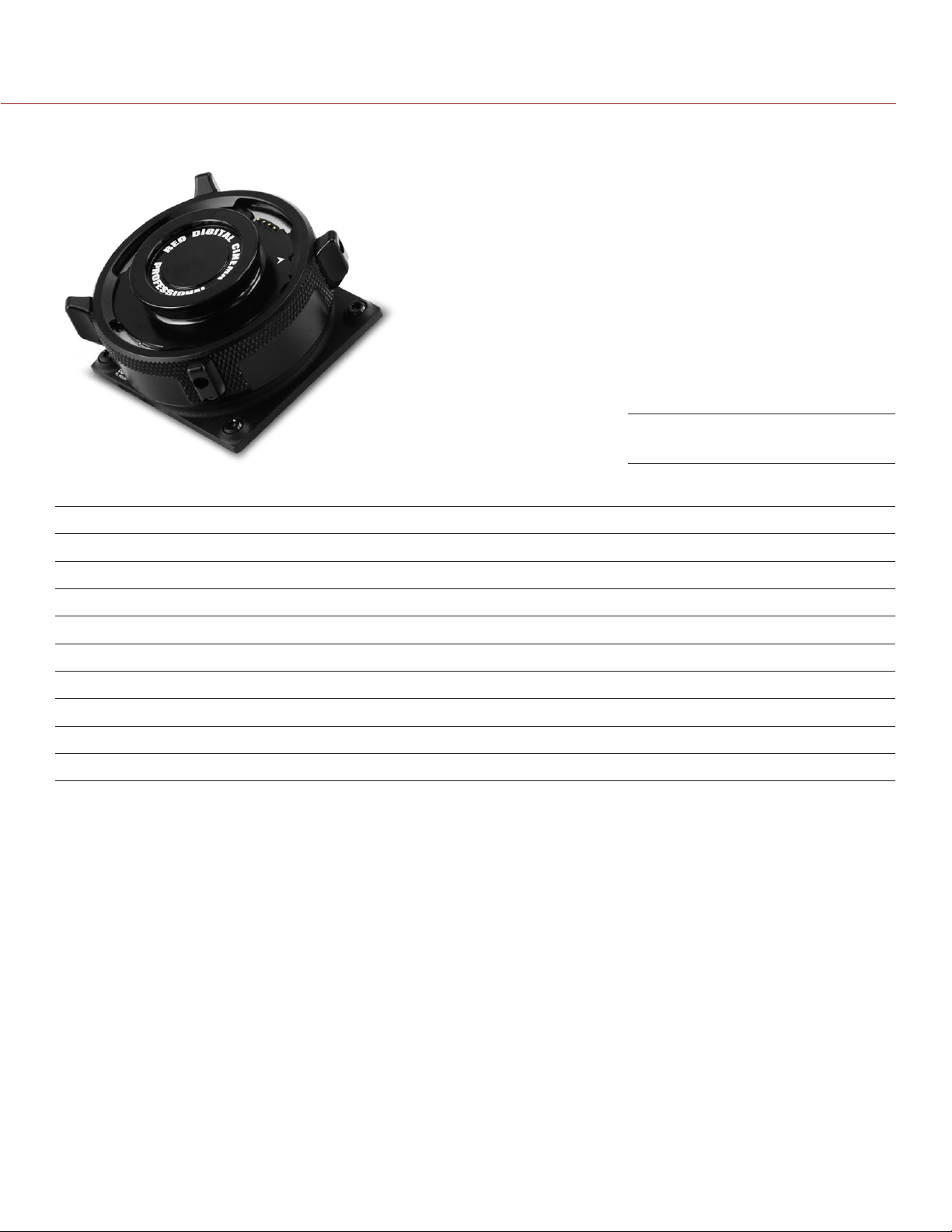
LENS MOUNTS
DSMC Mg PL Mount 2.0
RED offers the following lens mounts:
ITEM PART NUMBER
DSMC Mg PL Mount 2.0
1
725-0024
DSMC Ti PL Mount 725-0022
DSMC Al Canon Mount 725-0026
DSMC Ti Canon Mount 725-0005
DSMC Al Nikon Mount 725-0006
DSMC Ti Nikon Mount 725-0007
DSMC Al Leica-M Mount 725-0008
DSMC MOTION MOUNT Ti PL
DSMC MOTION MOUNT Ti Canon
1. For EPIC and SCARLET cameras, the DSMC Fan 2.0 (Bottom) and the DSMC Mg PL Mount 2.0 are not natively compatible with each
other, since the fan grill prevents the lens mount locking ring from rotating. To use these devices together, remove the lower tabs from the
locking ring using a T8 TORX® driver.
2. The DSMC RED MOTION MOUNT requires that your camera is on firmware v5.1.14 or later.
2
2
725-0012
725-0014
COPYRIGHT © 2016 RED.COM, INC
955-0020_V6.2, REV-J | 30
Page 31
EPIC/SCARLET OPERATION GUIDE
INTERCHANGEABLE OLPFS
This section describes the interchangeable optical low pass filter (OLPF) system and modular OLPFs.
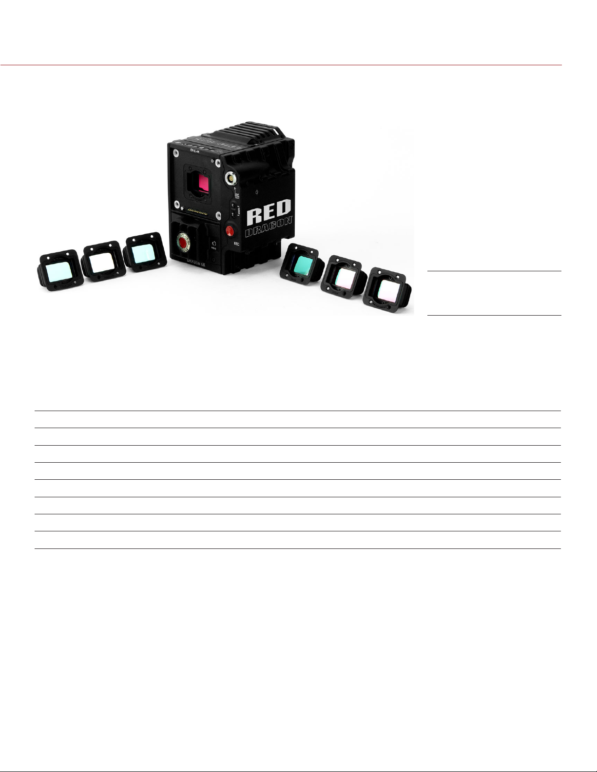
DSMC Interchangeable
OLPF System
NOTE: The DSMC interchangeable OLPF system is only compatible with the DRAGON sensor.
The DSMC interchangeable OLPF system is an upgrade to the optical low-pass filter (OLPF) in your EPIC
DRAGON or SCARLET DRAGON. The modular mounting system enables you to remove and replace OLPFs to
achieve optimal color reproduction in any lighting and environment.
For more information, go to “Use a Tripod or Monopod” on page 45.
RED offers the following modular DSMC interchangeable OLPFs for EPIC DRAGON and SCARLET DRAGON:
ITEM LABEL
DSMC Skin Tone-Highlight OLPF S 790-0461 v5.2.28 or later
DSMC Low Light Optimized OLPF L 790-0462 v5.2.28 or later
DSMC H
DSMC Standard OLPF D 790-0517 v6.0.37 or later
DSMC IR Pass OLPF (Color) I 790-0473 v5.3.33 or later
DSMC Monochrome OLPF
DSMC IR Pass OLPF (Monochrome)
1. Visible on the top inside part of the OLPF assembly.
2. Monochrome OLPFs are for use with the DRAGON Monochrome sensor ONLY.
O OLPF H 790-0472 v5.3.29 or later
2
2
2
1
PART NUMBER REQUIRED FIRMWARE
M 790-0481 v5.2.9 or later
I 790-0474 v5.3.33 or later
RAILS, MOUNTS, TACTICAL GEAR, AND CABLES
RED offers a wide variety of support gear, mounting platforms, cables, accessories, and other equipment. For
more information, visit the RED Store at www.red.com/store.
COPYRIGHT © 2016 RED.COM, INC 955-0020_V6.2, REV-J | 31
Page 32
EPIC/SCARLET OPERATION GUIDE
BASIC
03
OPERATIONS
POWER OPERATIONS
This section describes the basic power operations of the camera system.
For more information, see the DSMC Power Operation Guide, available at www.red.com/downloads.
WARNING: Modules and lens mounts are NOT HOT SWAPPABLE, meaning you cannot remove or install these
items while the camera is turned on. Before installing or removing these items, you MUST turn off the camera.
Failure to do so may result in damage to the item or camera that is not covered under warranty.
WARNING: While third-party batteries may be mechanically compatible with the camera system, the manufacturer
is responsible for the performance and stability of third-party options, not RED. Damage to the camera system
or third-party devices caused by using third-party power options is not covered under warranty. The camera
may be unable to determine and display the voltage or remaining battery capacity of third-party power options.
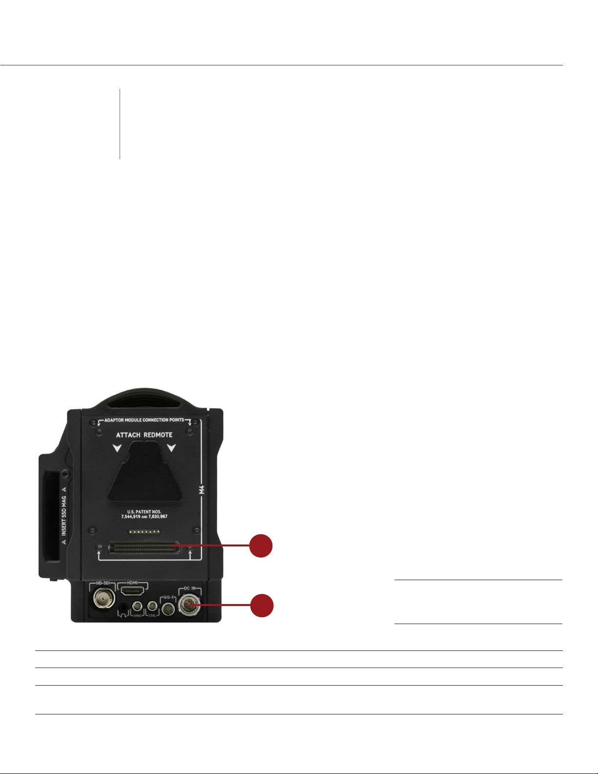
POWER INPUTS
1
SEARAY Connector (top) and
2
There are two (2) primary power inputs that provide power to the camera:
# POWER INPUT DESCRIPTION
1 SEARAY power connector Provides power to the camera from attached modules
2 DC IN connector Provides power to the camera using a DSMC Power Adaptor or certain
battery modules, such as the Backpack Quickplate
®
NOTE: Additionally, one (1) REDVOLT
short term power and support hot-swapping of other power sources.
COPYRIGHT © 2016 RED.COM, INC
battery may be used in conjunction with the DSMC Side Handle to provide
DC IN Connector (bottom)
955-0020_V6.2, REV-J | 32
Page 33

EPIC/SCARLET OPERATION GUIDE
POWER PRIORITY
When multiple power sources are connected to the camera, power consumption is prioritized in this sequence:
1. DC power supply (DC IN connector)
1. Attached RED BRICK
2. Battery module batteries (SEARAY connector; lowest state of charge first)
3. REDVOLT battery in an attached DSMC Side Handle
POWER CONSUMPTION
The camera draws approximately 60 W when recording in 5K resolution, at 24 fps.
Under typical conditions batteries provide the following operating time:
REDVOLT: Powers the camera and accessories for approximately 30 minutes.
REDVOLT XL: Powers the camera and accessories for approximately 90 minutes.
REDBRICK: Powers the camera and accessories for approximately 120 minutes.
RED BRICK: Powers the camera and accessories for approximately 120 minutes.
POWER STATUS
The power status of the current primary power source displays in the Lower Status Row of the graphical user
interface (GUI). Navigate to the Power In menu at Menu > Power > Power In for the status of all connected power
sources. For more information, go to “Power Menu” on page 101.
®
(Lowest state of charge first)
APPROVED EXTERNAL DC POWER
The camera accepts input voltages of 11.5 V to 17 V DC, and can draw a maximum current of 12 A. The camera
can be powered continuously by connecting one (1) of the following to the DC IN port on the camera:
DSMC AC Power Adaptor
RED BRICK Charger: Requires a 2B-to-1B Power Adaptor Cable.
RED BRICK: Requires a Backpack Quickplate or Battery Belt Clip (DSMC). Also supported by a RED Quickplate
or RED Cradle using a 2B-to-1B Power Adaptor Cable.
XLR DC power source: Requires an XLR Power Cable.
TURN ON THE CAMERA
1. Attach a power source to the camera.
The Power Status LED illuminates red, indicating that an appropriate power source is connected.
2. Press and release the PWR/REC key on the right side of the camera.
The Power Status LED turns off, and within five (5) seconds illuminates yellow as the camera turns on.
The Power Status LED then illuminates green to confirm that the camera is turned on and ready to use.
NOTE: The Power Status LED flashes red when there is less than five (5) minutes of operating time remaining.
TURN OFF THE CAMERA
Use one of the following methods to turn off the camera:
Go to Menu > Power and select Shutdown.
Press and hold PWR/REC until the Shutting Down... notification shows on the display.
NOTE: The camera turns off automatically if the supply voltage drops to 11.5 V.
COPYRIGHT © 2016 RED.COM, INC 955-0020_V6.2, REV-J | 33
Page 34
EPIC/SCARLET OPERATION GUIDE
CONFIGURE YOUR CAMERA
This section describes common options for configuring your camera system.
INSTALL THE DSMC SIDE HANDLE
WARNING: Before installing or removing the DSMC Side Handle, you MUST turn off the camera.
REQUIRED TOOL: T10 TORX
1. Turn off the camera.
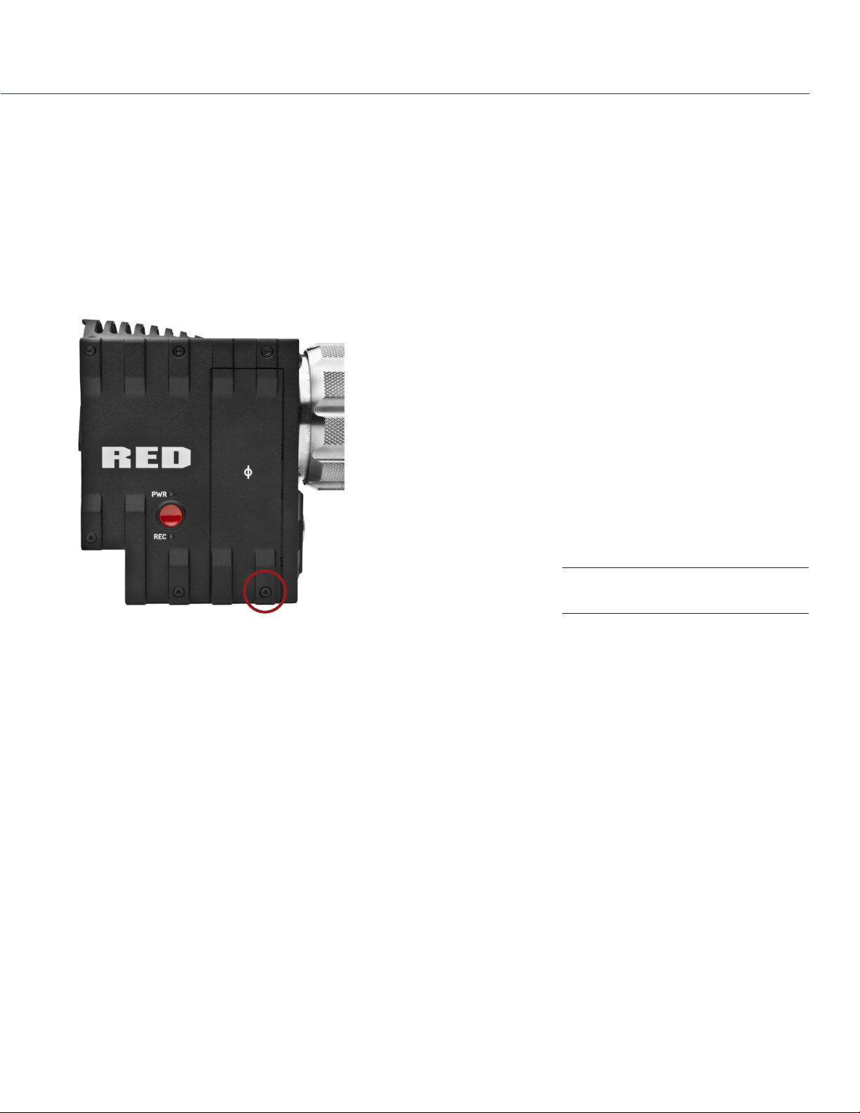
2. Use a T10 TORX driver to remove the single screw located at the bottom of the BRAIN side plate (if the
side plate is installed).
®
driver
Remove the BRAIN Side Plate
3. Rotate the BRAIN side plate upwards to disengage the lip at the top of the side plate from the camera, and
remove the BRAIN side plate.
4. Insert the lip on the DSMC Side Handle into the slot where the lip of the BRAIN side plate was installed.
5. Press the DSMC Side Handle down flush along the side of the camera.
6. Rotate the thumbscrew upward while applying steady pressure until tight.
REMOVE THE DSMC SIDE HANDLE
WARNING: Before installing or removing the DSMC Side Handle, you MUST turn off the camera.
REQUIRED TOOL: T10 TORX driver
1. Turn off the camera.
2. Rotate the thumbscrew downward until the DSMC Side Handle detaches from the camera body.
3. Disengage the tension lip on the DSMC Side Handle by pulling the bottom away from the camera.
4. Insert the tension lip on the BRAIN side plate into the recess on the side of the camera.
5. Install the appropriate screw at the bottom of the BRAIN side plate using a T10 TORX driver. DO NOT
exceed 70 in-oz, or damage may occur.
‒ EPIC side plate screw: M3x0.5 x 8 mm
‒ SCARLET side plate screw: M3x0.5 x 5.5 mm
WARNING: DO NOT OVERTIGHTEN.
COPYRIGHT © 2016 RED.COM, INC
955-0020_V6.2, REV-J | 34
Page 35

EPIC/SCARLET OPERATION GUIDE
INSTALL THE RED SWITCHBLADE-M
WARNING: Before installing or removing the RED Switchblade-M, you MUST turn off the camera.
REQUIRED TOOL: T10 TORX driver
1. Turn off the camera.
2. Use a T10 TORX driver to remove the single screw located at the bottom of the BRAIN side plate (if the
side plate is installed).
3. Rotate the BRAIN side plate upwards to disengage the lip at the top of the side plate from the camera, and
remove the BRAIN side plate.
4. Insert the lip on the RED Switchblade-M into the slot where the lip of the BRAIN side plate was installed.
5. Press the Switchblade-M down flush along the side of the camera.
6. Tighten the thumbscrew until finger-tight, then enage the thumbscrew mechanism.
REMOVE THE RED SWITCHBLADE-M
WARNING: Before installing or removing the RED Switchblade-M, you MUST turn off the camera.
REQUIRED TOOL: T10 TORX driver
1. Turn off the camera.
2. Disengage the thumbscrew mechanism.
3. Loosen the thumbscrew until the Switchblade-M detaches from the camera.
4. Pull the bottom of the RED Switchblade-M away from the camera to disengage the tension lip.
5. Remove the RED Switchblade-M from the camera.
6. Insert the tension lip on the BRAIN side plate into the recess on the side of the camera.
7. Install the appropriate screw at the bottom of the BRAIN side plate using a T10 TORX driver. DO NOT
exceed 70 in-oz, or damage may occur.
‒ EPIC side plate screw: M3x0.5 x 8 mm
‒ SCARLET side plate screw: M3x0.5 x 5.5 mm
WARNING: DO NOT OVERTIGHTEN.
COPYRIGHT © 2016 RED.COM, INC 955-0020_V6.2, REV-J | 35
Page 36
EPIC/SCARLET OPERATION GUIDE
INSTALL THE MODULE ADAPTOR
You must install an adaptor module on the back of the camera before you install a module.
REQUIRED TOOL: T20 TORX driver
1. Turn off the camera.
2. Remove the REDMOTE, if attached.
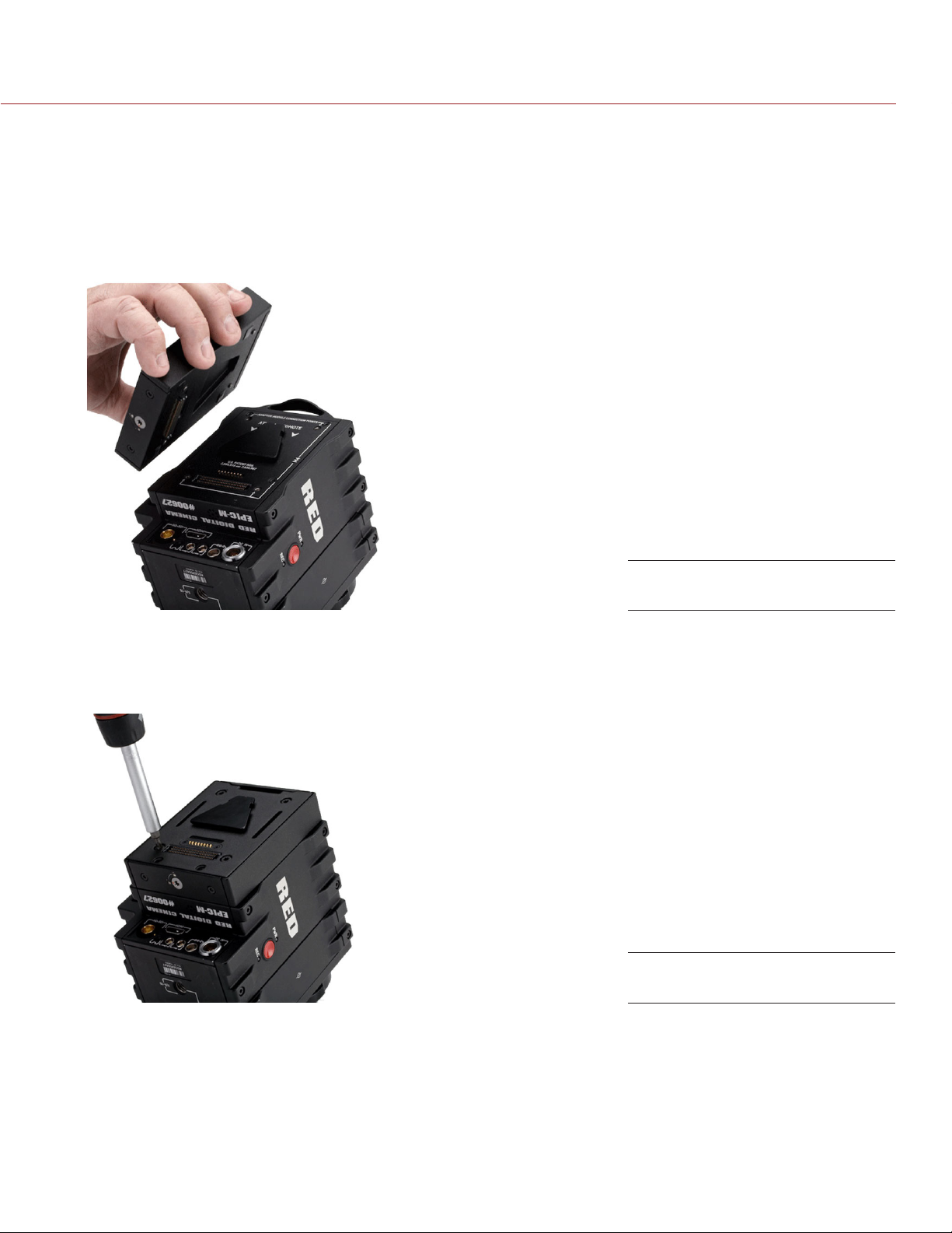
3. Position the Module Adaptor over the V-mount on the rear of the camera.
Install Module Adaptor
4. Apply pressure and tighten the four (4) captive screws in a cross pattern (“X” pattern) approximately two (2)
turns each using a T20 TORX driver. DO NOT FULLY TIGHTEN.
5. Fully tighten the four (4) screws in a cross pattern (“X” pattern) using a T20 TORX driver.
WARNING: DO NOT OVERTIGHTEN.
Tighten screws
COPYRIGHT © 2016 RED.COM, INC
955-0020_V6.2, REV-J | 36
Page 37
EPIC/SCARLET OPERATION GUIDE
REMOVE THE MODULE ADAPTOR
REQUIRED TOOL: T20 TORX driver
1. Turn off the camera.
2. Use a T20 TORX driver to loosen the screws attaching the Module Adaptor to the camera.
3. Remove the Module Adaptor from the camera.
INSTALL THE +1 ADAPTOR MODULE
REQUIRED TOOL: T20 TORX driver
1. Turn off the camera.
2. Remove the REDMOTE, if attached.
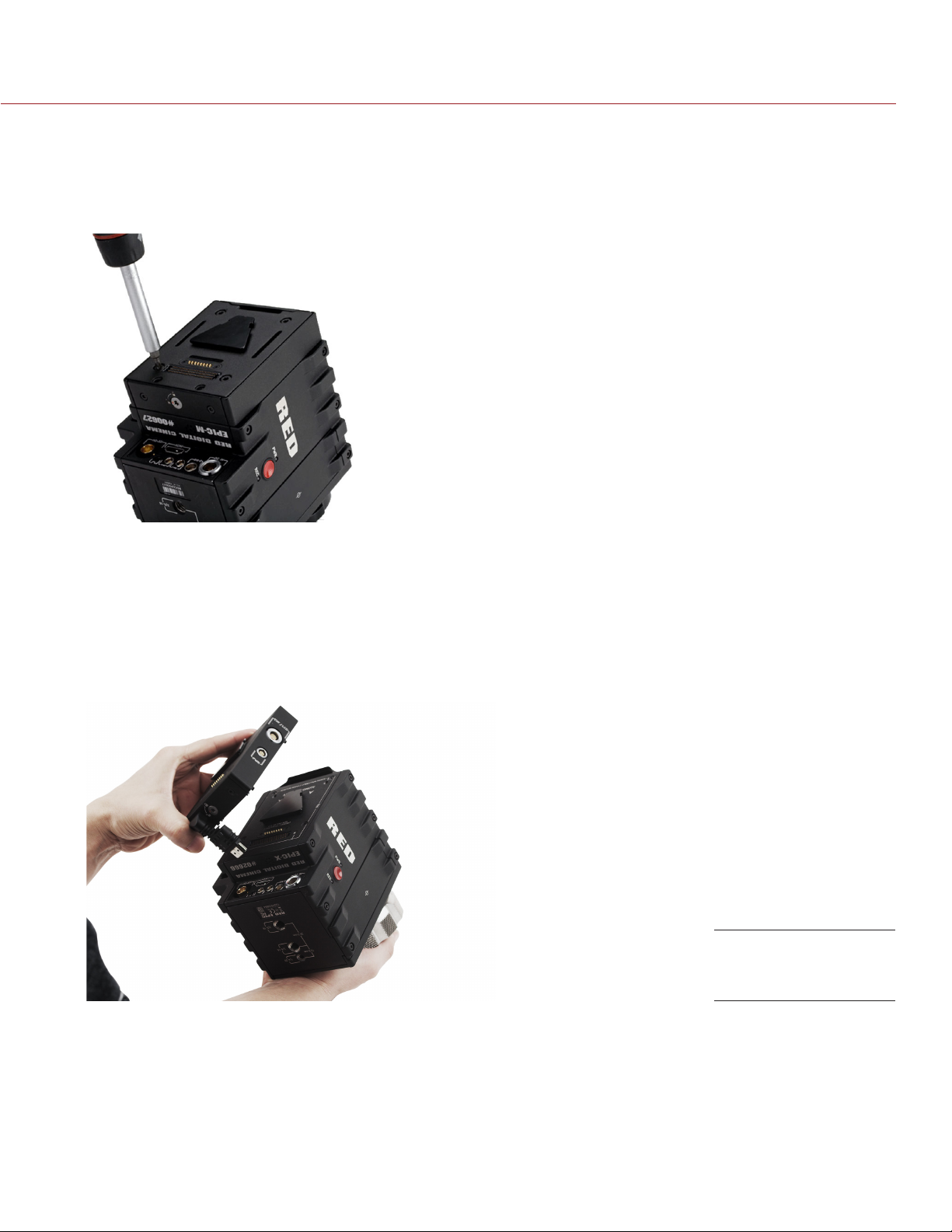
3. Position the +1 Adaptor Module over the V-mount on the rear of the camera.
Install the +1 Module
Adaptor
COPYRIGHT © 2016 RED.COM, INC 955-0020_V6.2, REV-J | 37
Page 38
EPIC/SCARLET OPERATION GUIDE
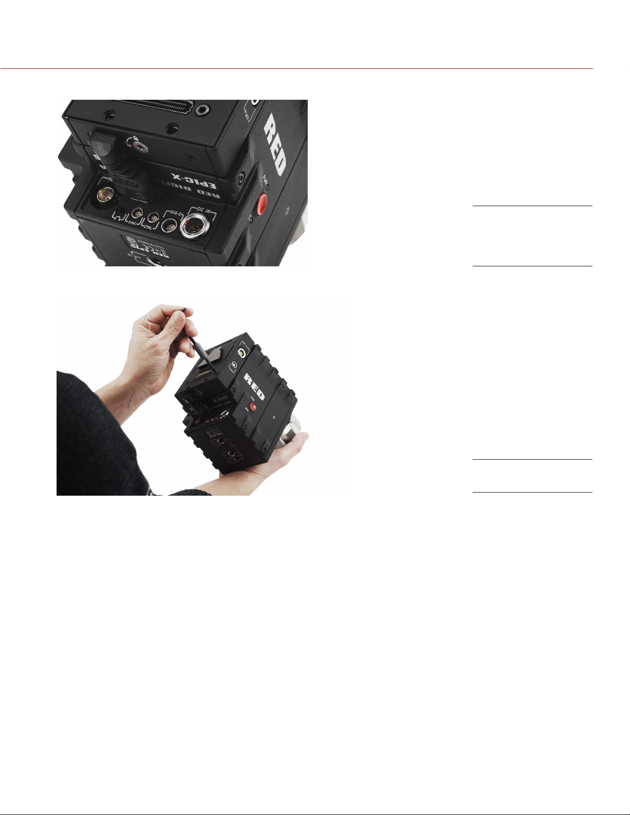
4. Insert the HDMI connector into the HDMI port on the camera.
Insert the HDMI
connector to the
BRAIN
5. Apply pressure and tighten the four (4) captive screws in a cross pattern (“X” pattern) approximately two (2)
turns each using a T20 TORX driver. DO NOT FULLY TIGHTEN.
Tighten screws
6. Fully tighten the four (4) screws in a cross pattern (“X” pattern) using a T20 TORX driver.
WARNING: DO NOT OVERTIGHTEN.
REMOVE THE +1 ADAPTOR MODULE
REQUIRED TOOL: T20 TORX driver
1. Turn off the camera.
2. Loosen the four (4) captive mounting screws in a cross pattern (“X” pattern) using a a T20 TORX driver.
3. Disconnect the HDMI connector from the camera.
4. Remove the +1 Adaptor Module from the camera.
COPYRIGHT © 2016 RED.COM, INC
955-0020_V6.2, REV-J | 38
Page 39
EPIC/SCARLET OPERATION GUIDE
ATTACH A MODULE
REQUIRED TOOL: T20 TORX driver
1. Turn off the camera.
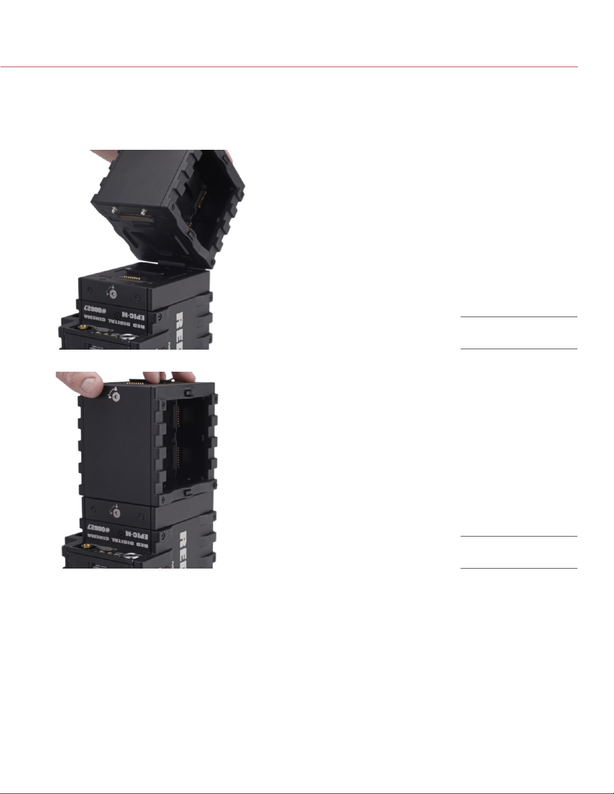
2. Insert the lip at the top of the module into the recess at the top of the adaptor module.
Insert module lip
3. Rotate the module down flush with the rear of the adaptor module.
Press module flush
4. Apply pressure and use a T20 TORX driver to turn the lock on the bottom of the adaptor module clockwise
into the Lock position.
REMOVE A MODULE
REQUIRED TOOL: T20 TORX driver
1. Turn off the camera.
2. Use a T20 TORX driver to turn the lock on the adaptor module counter-clockwise to the Unlock position.
3. Rotate the module upwards and away from the adaptor module to disengage.
4. Remove the module.
COPYRIGHT © 2016 RED.COM, INC 955-0020_V6.2, REV-J | 39
Page 40
EPIC/SCARLET OPERATION GUIDE
REPLACE THE HOOD SCOOP
REQUIRED TOOL: T8 TORX driver
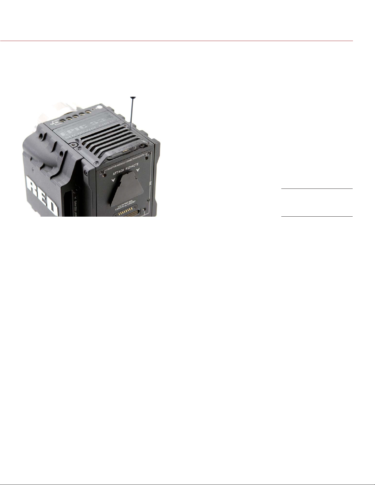
The hood scoop on some EPIC-X and EPIC-M models extends beyond the rear plane of the camera. RED offers
shorter hood scoops so that you can attach an LCD or other accessory to the mounting locations on the top
of the +1 Adaptor Module.
Replace the hood
scoop
To replace fan hood scoop, follow the instructions below:
1. Turn off the camera.
2. Remove the four (4) M3x0.5 x 6 mm screws holding the hood scoop using a T8 TORX driver.
3. Remove the hood scoop.
4. Position the replacement hood scoop on the camera.
5. Align the hood scoop screw holes with the threaded holes.
6. Insert and tighten the four (4) M3x0.5 x 6 mm screws in a cross pattern (“X” pattern) using a T8 TORX driver.
DO NOT FULLY TIGHTEN.
7. Fully tighten the four (4) M3x0.5 x 6 mm cap screws evenly in a cross pattern (“X” pattern). DO NOT exceed
30 in-oz, or damage may occur.
WARNING: DO NOT OVERTIGHTEN.
COPYRIGHT © 2016 RED.COM, INC
955-0020_V6.2, REV-J | 40
Page 41
EPIC/SCARLET OPERATION GUIDE
INTERCHANGEABLE OLPF SYSTEM
This section describes the process for swapping an interchangeable OLPF.
WARNING: Read these instructions carefully and in their entirety before removing or installing an interchangeable
OLPF. Damage caused to the OLPF module, camera, or sensor due to improper handling or use is not covered
under warranty.
WARNING: Once an interchangeable OLPF is removed from the camera, the sensor is exposed. Improper handling
of the OLPF modules or camera during this procedure may compromise the installation or cause irreparable
damage to your camera or sensor.
WARNING: DO NOT allow any dirt or debris to enter the optical cavity.
WARNING: This procedure is ONLY applicable to DRAGON sensor cameras that are compatible with the DSMC
Interchangeable OLPF system.
WARNING: Use only DSMC OLPFs. DO NOT use DSMC2 OLPFs. For any questions about OLPF compatibility,
please contact your Bomb Squad representative.
SWAP AN INTERCHANGEABLE OLPF
REQUIRED TOOLS: T20 TORX driver, T6 TORX driver
1. Turn off the camera.
2. Remove any modules, cables, or other accessories that may interfere with operations.
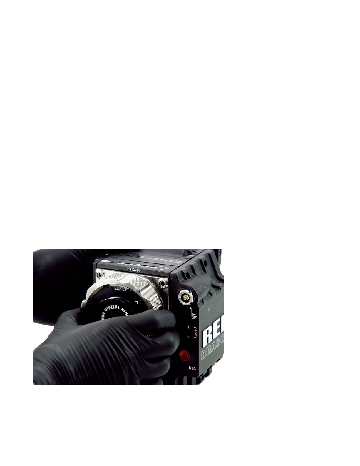
3. Loosen and remove the four (4) M4x0.7 x 8 mm lens mount screws in a cross pattern (“X” pattern) using a
T20 TORX driver.
NOTE: The DSMC Mg PL Mount 2.0 has captive screws that are not removable from the mount.
NOTE: Screw removal may require a large handle T20 TORX driver and additional leverage.
4. Remove the lens mount.
Remove Lens Mount
5. Use a damp, lint-free cloth to gently wipe down the area around the lens mount and OLPF module. Remove
as much dust and debris as possible.
COPYRIGHT © 2016 RED.COM, INC 955-0020_V6.2, REV-J | 41
Page 42
EPIC/SCARLET OPERATION GUIDE
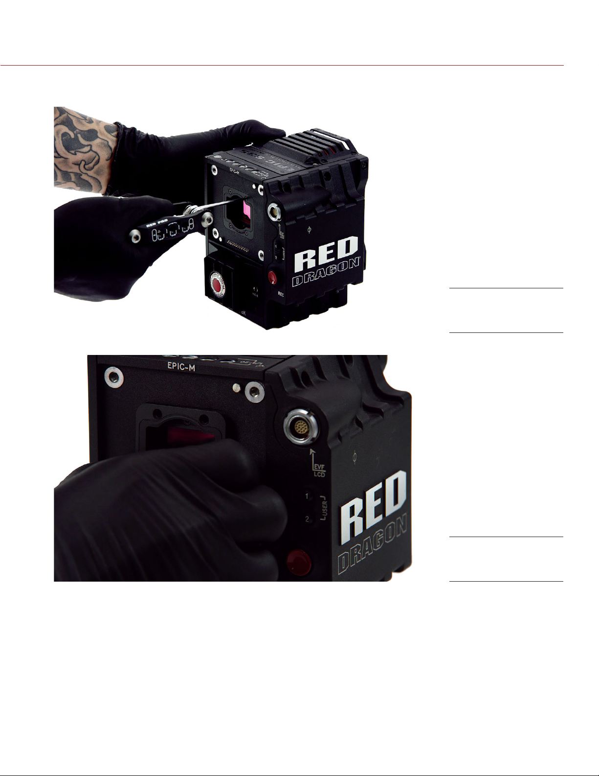
6. Remove the four (4) M2x0.4 x 4 mm OLPF module screws (P/N 600-0224) in a cross pattern (“X” pattern)
using a T6 TORX driver.
Remove OLPF
module screws
7. Remove the OLPF module and place it in its protective case.
Remove the OLPF
module
COPYRIGHT © 2016 RED.COM, INC
955-0020_V6.2, REV-J | 42
Page 43
EPIC/SCARLET OPERATION GUIDE
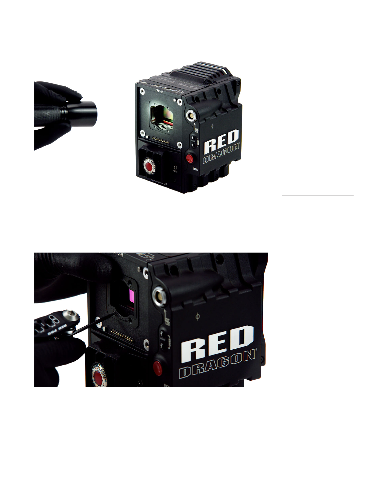
8. Use an LED light to ensure that the optical cavity is clean and free from dust or debris.
Ensure optical cavity
is clean and free of
debris
9. Ensure the new OLPF module is clean and free of debris.
10. Install the new OLPF module straight into the optical cavity, keeping the front face of the OLPF module
parallel to the front of the camera.
NOTE: Inserting the OLPF module at an angle may cause it to not seat properly.
11. Replace and loosely tighten the four (4) M2x0.4 x 4 mm OLPF module screws (P/N 600-0224) in a cross
pattern (“X” pattern) using a T6 TORX driver. DO NOT FULLY TIGHTEN.
Replace the OLPF
module and screws
12. Fully tighten the four (4) OLPF module screws in a cross pattern (“X” pattern) using a T6 TORX driver. DO
NOT exceed 30 in-oz, or damage may occur.
WARNING: DO NOT OVERTIGHTEN.
13. Replace the lens mount.
COPYRIGHT © 2016 RED.COM, INC 955-0020_V6.2, REV-J | 43
Page 44
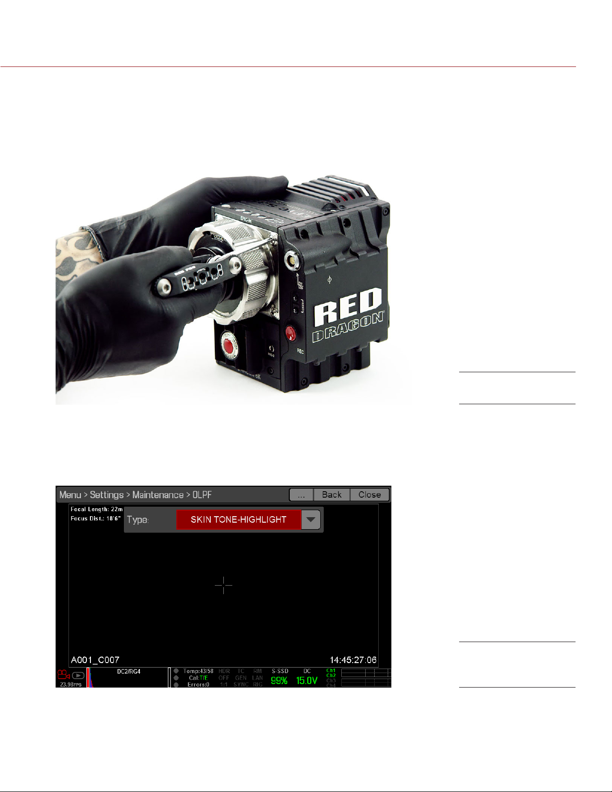
EPIC/SCARLET OPERATION GUIDE
14. Replace and loosely tighten the four (4) M4x0.7 x 8 mm lens mount screws in a cross pattern (“X” pattern)
using a T20 TORX driver. DO NOT FULLY TIGHTEN.
NOTE: The DSMC Mg PL Mount 2.0 has captive screws that are not removable from the mount.
15. Fully tighten the four (4) lens mount screws in a cross pattern (“X” pattern) using a T20 TORX driver. DO
NOT exceed 350 in-oz, or damage may occur.
NOTE: DO NOT OVERTIGHTEN.
Replace Lens Mount
16. Turn on the camera.
17. Go to Menu > Settings > Maintenance > OLPF.
18. Select the installed OLPF from the Type drop-down menu.
IMPORTANT: Ensure the correct OLPF type is selected from the drop-down menu. Failure to select the
correct OLPF type will affect color accuracy. For more information, go to “OLPF” on page 114.
OLPF Type menu
selection
COPYRIGHT © 2016 RED.COM, INC
955-0020_V6.2, REV-J | 44
Page 45
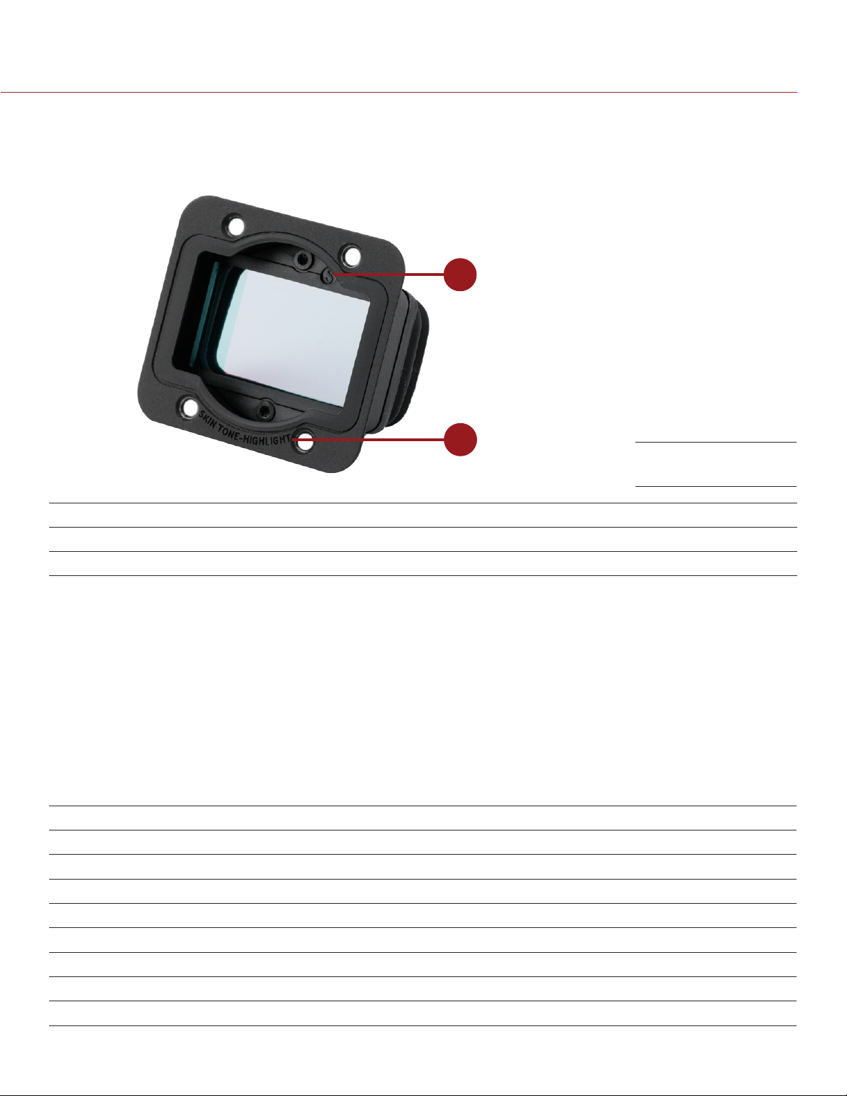
EPIC/SCARLET OPERATION GUIDE
VERIFY INSTALLED OLPF
You can see which DSMC interchangeable OLPF is installed even when a lens mount is attached. The OLPF
type is labeled in two (2) locations on each DSMC interchangeable OLPF.
1
2
OLPF Type Labels
# LOCATION ON ASSEMBLY LABEL VISIBLE WITH
1 Top inside Identifier symbol, such as (S) PL mounts
2 Front bottom OLPF type All mounts
USE A TRIPOD OR MONOPOD
This section describes the camera mounting points and mounting equipment for use with a tripod or monopod.
The camera is equipped with two (2) 3/8-16 mounting holes and one (1) 1/4-20 mounting hole on the bottom
of the camera. These mounting points are designed for use with a variety of mounting plates and hardware, to
support tripods and other support systems.
WARNING: Ensure that the tripod, monopod, or support system is designed and rated to handle the weight of
your camera configuration. RED is not responsible for any damage caused by using a tripod, monopod, mount,
or support system that does not provide sufficient support.
WARNING: DO NOT use excessive force to mount a support accessory, as this may damage the screw threading.
RED offers the following products for use with tripods and other support systems:
ITEM PART NUMBER
Mounting Plate (DSMC) 790-0094
DSMC Modular Assault Plate Pack 790-0224
DSMC Quick Release Platform Pack 790-0183
Quick Release Platform Pack (Bolt-On) 790-0078
Quick Release Platform (Dovetail) 790-0079
Quick Release Platform (Mini) 790-0390
Dovetail Mounting Plate (Long) 790-0083
Dovetail Mounting Plate (Short) 790-0084
For more information, visit the RED store at www.red.com/store.
COPYRIGHT © 2016 RED.COM, INC 955-0020_V6.2, REV-J | 45
Page 46

EPIC/SCARLET OPERATION GUIDE
VIDEO MONITOR OUTPUTS
The monitoring path converts RAW sensor data to a white balanced 12-bit depth 1920 x 1080 pixel RGB 4:4:4
video signal. The signal may be modified using ISO, White Balance, or other RGB color space adjustments. The
signal is then scaled and gamma-corrected to provide monitor outputs at 10-bit depth in 4:2:2 YCC or 8-bit
depth in 4:4:4 RGB.
The camera offers the following monitor outputs:
EVF/LCD: Supports a RED EVF or LCD display.
HD-SDI: Provides a 720p or 1080p output suitable for monitoring or recording to an external VTR or DDR
device. It may be configured for 10-bit LIN (VIDEO) or 10-bit LOG (FILM) encoded data.
HDMI: Provides a 480p, 720p, or 1080p output suitable for monitoring via a Windows® monitor or most
HDTVs.
VIDEO MONITOR CATEGORIES
Video monitor outputs are separated into three (3) categories:
VIEWFINDER: The Upper Status Row, Live Action Area, and Lower Status Row display. Default output is the
EVF/LCD connector located on the front face of the side SSD module. If an EVF or LCD is not connected,
you can transfer the VIEWFINDER output to either the HDMI or 3G-SDI (HD-SDI) output from the camera.
PROGRAM/Clean: None of the graphic overlays display.
PREVIEW: The Live Action Area and associated graphic overlays display.
For more information about changing the video monitor category of your monitor, go to “Monitor Control” on
page 57.
RECORD
Perform one of the following actions to begin recording:
Press PWR/REC on the camera.
Press REC on an attached side SSD module.
Press REC on an attached DSMC Side Handle.
Double-tap the right 25% on an attached touchscreen display (when enabled).
NOTE: To enable Double-Tap Right 25% to Record, go to Menu > Settings > Display > Monitor Control > Advanced
> Gestures.
RECORD VIA HD-SDI OR HDMI
This section describes how to record via HD-SDI or HDMI through simultaneous record (recording to an SSD
and an external recorder at the same time) or external record only. For more information on how to enable
default menus for a external recorder, go to “Cannot Use Touchscreen or DSMC2 Sidekick” on page 151.
SIMULTANEOUS RECORD
You can record simultaneously to an external recorder and a RED SSD. To record simultaneously, follow the
instructions below:
1. Connect the camera to an external recorder with an HD-SDI or HDMI cable.
2. Ensure an SSD is inserted in the camera and formatted.
3. Begin recording.
COPYRIGHT © 2016 RED.COM, INC
955-0020_V6.2, REV-J | 46
Page 47

EPIC/SCARLET OPERATION GUIDE
EXTERNAL RECORD
You can record to an external recorder without recording to an SSD. To record to an external device only, follow
the instructions below:
1. Connect the camera to an external recorder with an HD-SDI or HDMI cable.
2. Ensure the SSD is ejected.
3. Go to Menu > Settings > Recording > Mode.
4. Select External from the Storage drop-down menu.
5. Begin recording.
COPYRIGHT © 2016 RED.COM, INC 955-0020_V6.2, REV-J | 47
Page 48
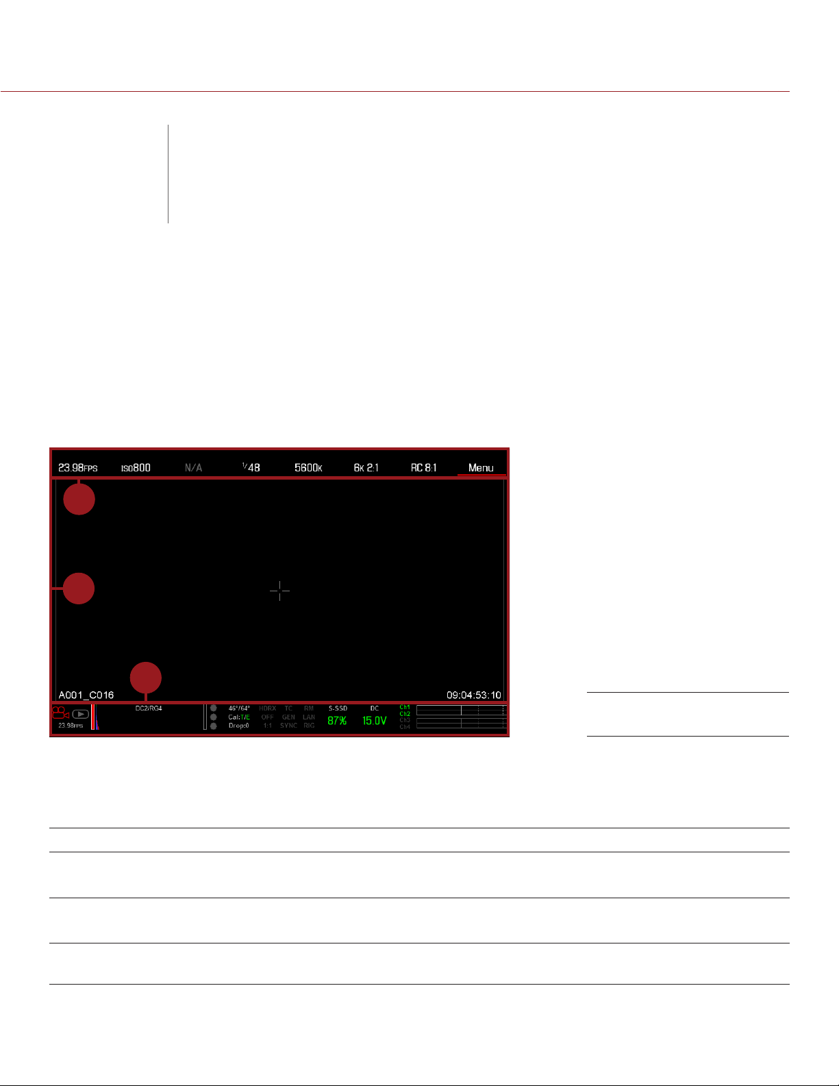
EPIC/SCARLET OPERATION GUIDE
BASIC MENUS
04
This chapter describes the Basic Menus and controls, including:
“Upper Status Row (Basic Menu)” on page 49
“Live Action Area” on page 53
“Lower Status Row” on page 54
“Navigation Controls” on page 59
AND CONTROLS
GUI MENU INTRODUCTION
1
2
3
GUI Control Menu
This section describes the structure and layout of the graphical user interface (GUI) that overlays the video
monitor signal. Advanced GUI menu controls enable convenient access to menus, overlays, and other critical
camera information. Functionality varies based on monitor output type and firmware version.
The GUI menu is separated into three (3) main sections:
# ITEM DESCRIPTION
1 Upper Status Row
(Basic Menu)
2 Live Action Area Live camera recording view, overlays, guides, and more.
3 Lower Status Row Critical camera parameters, record/playback modes, media and power status,
COPYRIGHT © 2016 RED.COM, INC
Easy access to primary camera capture parameters.
Go to “Upper Status Row (Basic Menu)” on page 49.
Go to “Live Action Area” on page 53.
and audio meter. Go to “Lower Status Row” on page 54.
955-0020_V6.2, REV-J | 48
Page 49
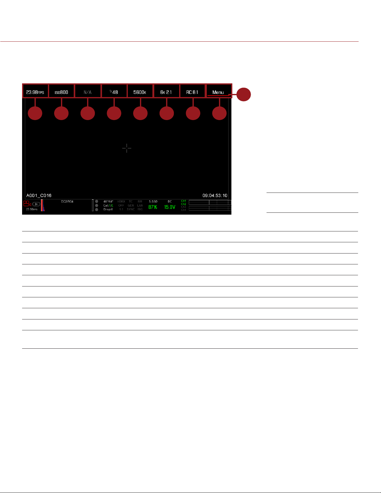
EPIC/SCARLET OPERATION GUIDE
UPPER STATUS ROW (BASIC MENU)
The Upper Status Row displays basic project parameters. The currently selected parameter in the Upper Status
Row is underlined with a red bar. The Upper Status Row is also known as the Basic Menu.
9
1 52 8763 4
Upper Status Row
The Upper Status Row includes the following GUI elements:
# ITEM DESCRIPTION FOR MORE INFORMATION, GO TO...
1 Frame Rate (fps) Recording frame rate “Frame Rate” on page 69
2 ISO Camera sensitivity “ISO” on page 65
3 Aperture Lens aperture (F stop) information “Aperture” on page 52
4 Exposure (Shutter) Integration time or shutter angle “Exposure” on page 84
5 Color Temperature White balance “Color Temperature” on page 68
6 Resolution Record resolution “Format” on page 71
7 REDCODE
8 Menu Access advanced settings “Advanced Menus” on page 53
9 Cursor Indicates currently selected Upper
®
REDCODE compression setting “REDCODE” on page 52
N/A
Status Row element
COPYRIGHT © 2016 RED.COM, INC 955-0020_V6.2, REV-J | 49
Page 50
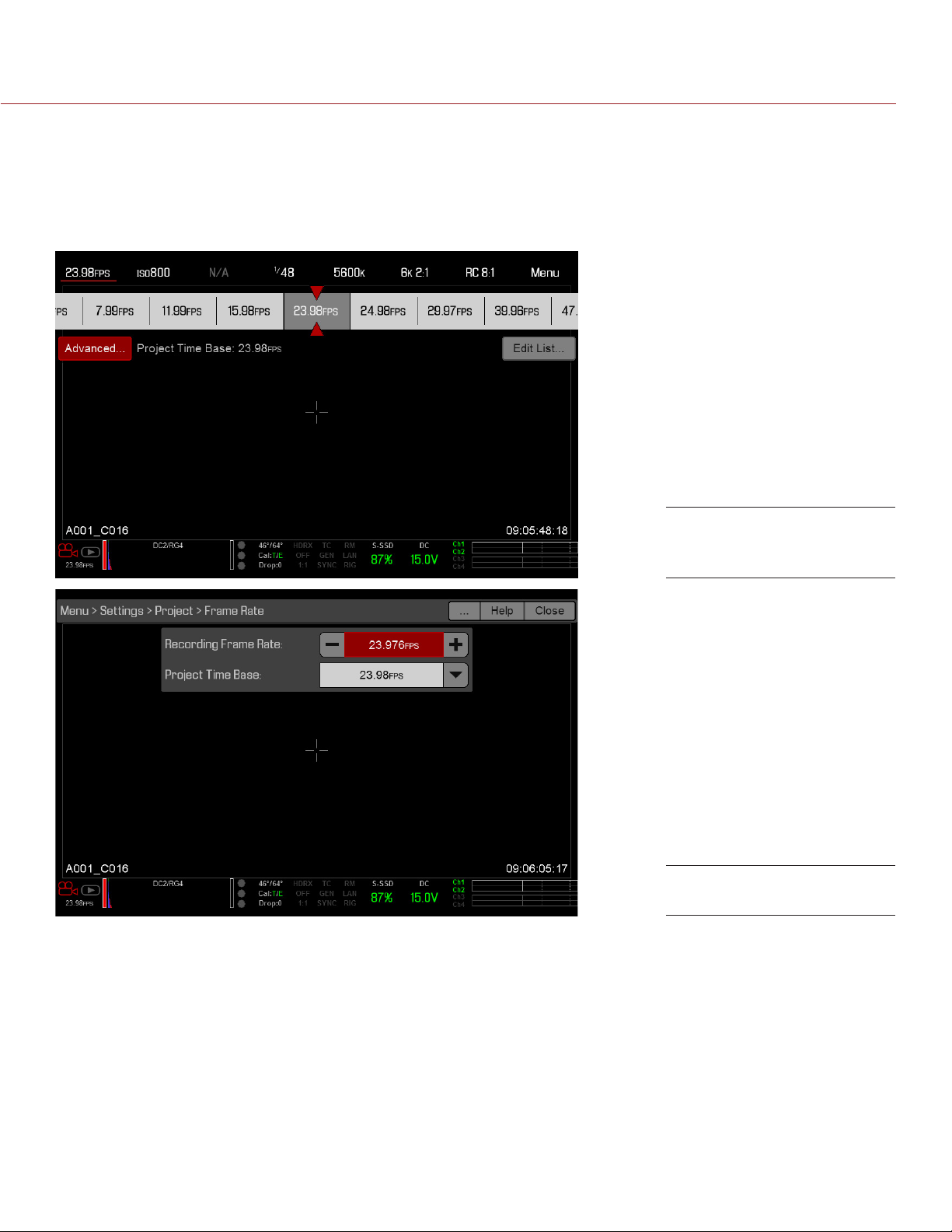
EPIC/SCARLET OPERATION GUIDE
ACCESS ADVANCED MENUS
For every Upper Status Row item, you can select the Advanced... button to access the related menu in the
Advanced Menus.
For example, select Advanced... in the Frame Rate menu to open Menu > Settings > Project > Frame Rate.
For more information about Advanced Menus, go “Advanced Menus” on page 66.
Select “Advanced...”
Button
“Advanced...” Menu
COPYRIGHT © 2016 RED.COM, INC
955-0020_V6.2, REV-J | 50
Page 51
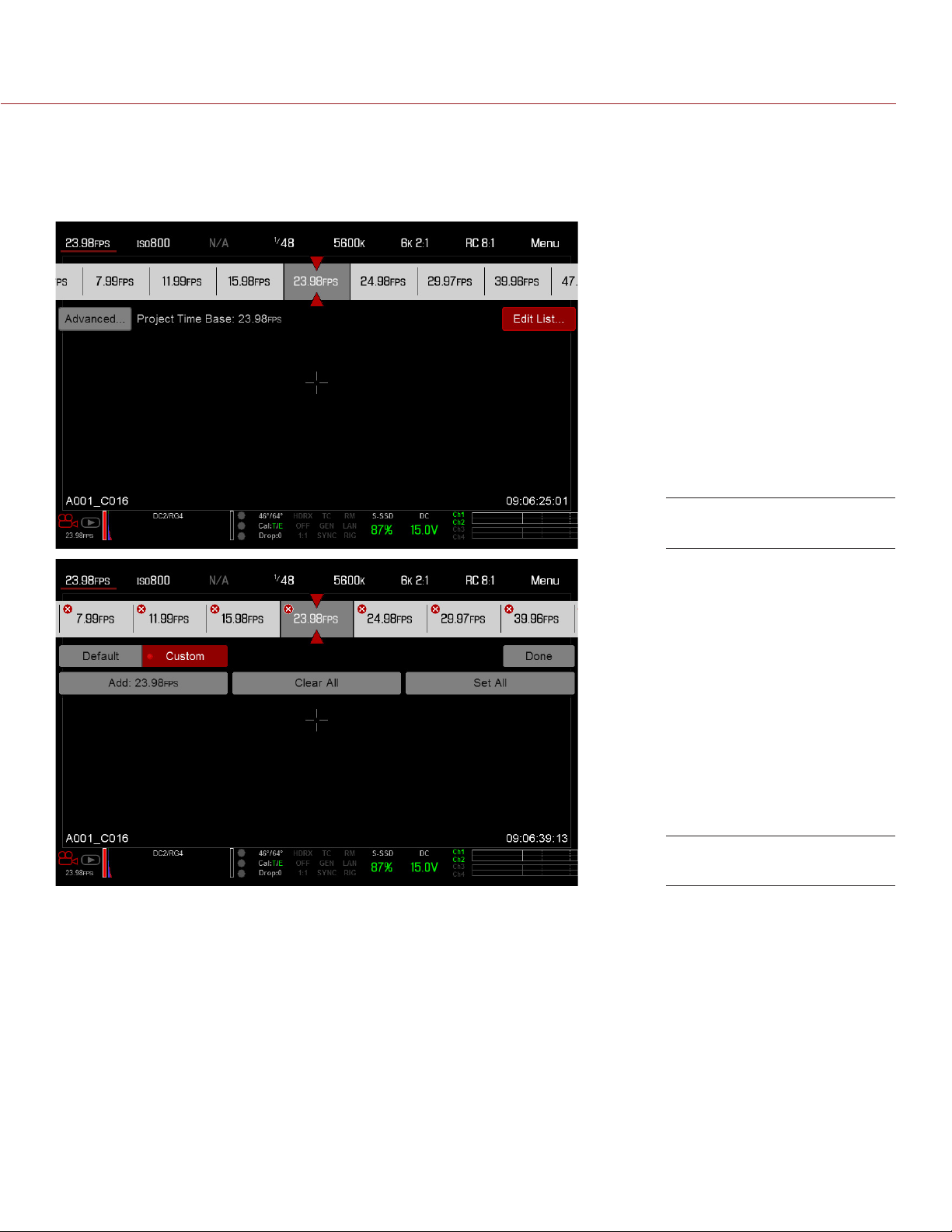
EPIC/SCARLET OPERATION GUIDE
FEATURE: EDIT LIST
Select the Edit List... button in the Upper Status Row menus to change the values that display for each setting.
For example, if you open the Frame Rate menu and select Edit List..., the camera lets you add or remove values
to available frame rates.
Select “Edit List...” Button
“Edit List...” Menu
COPYRIGHT © 2016 RED.COM, INC 955-0020_V6.2, REV-J | 51
Page 52

EPIC/SCARLET OPERATION GUIDE
APERTURE
The aperture (also known as the T stop or F stop) parameter displays when a compatible mount and lens are
installed. The aperture controls the depth of field of the image and, in combination with the shutter speed/angle
setting, controls the amount of light that reaches the sensor (exposure).
Increasing the aperture to a higher number increases the depth of field, but reduces the exposure (brightness).
Decreasing the aperture to a lower number decreases the depth of field, but increases the exposure
(brightness).
RED DSMC PL MOUNT INSTALLED
The current aperture of the attached lens displays when a DSMC® PL mount is installed and a supported lens
equipped with Cooke® S4/i® system is attached.
DSMC NIKON MOUNT AND CANON MOUNTINSTALLED
The Aperture menu is visible when a DSMC Nikon® Mount, DSMC Canon® Mount, or DSMC RED® MOTION MOUNT
Ti Canon is installed and a supported lens is attached. This enables you to adjust the aperture of the attached
lens.
Select the Advanced... button to access the Menu > Settings > Setup > Lens screen. For more information, go to
“Autofocus Modes” on page 104.
REDCODE
Select the target REDCODE compression ratio for your project.
If the camera is able to achieve the target compression ratio, the compression ratio displays in white. If the
camera is unable to achieve the target compression ratio, the compression ratio displays in yellow.
The current compression ratio is automatically recalculated when changes are made to the project resolution,
aspect ratio, anamorphic setting, frame rate, HDRx mode, media, or the target REDCODE compression ratio.
The RECODE compression affects the overall quality of the footage. A lower compression (for example: 2:1)
increases the quality of the footage, while a higher compression (for example: 22:1) lowers the quality.
For more information, go to “R3D File Format and REDCODE” on page 8.
MYSTERIUM-X: Range is 3:1 to 18:1. Default is 8:1.
RED DRAGON: Range is 2:1 to 22:1. Default is 8:1.
For maximum available REDCODE values, see the DSMC Media Operation Guide at www.red.com/downloads.
COPYRIGHT © 2016 RED.COM, INC
955-0020_V6.2, REV-J | 52
Page 53

EPIC/SCARLET OPERATION GUIDE
LIVE ACTION AREA
The Live Action Area contains the recorded image area plus Surround View look around area, plus overlays
for Frame Guides, Safe Action/Safe Title, Clip Name, and Timecode values. The color of each overlay can be
customized to maximize the contrast between the guide(s) and scene being captured.
1
3
5
The Live Action Area includes the following GUI elements:
# ITEM DESCRIPTION FOR MORE INFORMATION, GO TO...
1 Lens Information Lens information when using supported
2 AF Status Currently selected auto focus mode “Focus Menu” on page 102
3 Center Crosshair and
Spot Focus Guide
2
4
6
Canon, Nikon, or Cooke lenses
Crosshair: Center of selected guide
Reference guides: Safe Action/Safe Title,
Picture Center, Grid Overlay
Live Action Area
“Lens Information” on page 53
“General Tab” on page 64
4 Frame Guides Record or sensor projection area “Guides” on page 63
5 Clip Filename Filename of the clip being recorded, or
filename of the next clip to be recorded
6 Timecode Value Current timecode value “Timecode” on page 71
DSMC Media Operation Guide
LENS INFORMATION
This section describes the lens information displays when a supported lens is attached.
PL LENSES
Displays the focal length and focal distance when a DSMC PL mount is installed and a lens with the Cooke S4/i
system (or equivalent) is attached. For more information, go to “Lens Tab” on page 63.
COPYRIGHT © 2016 RED.COM, INC 955-0020_V6.2, REV-J | 53
Page 54
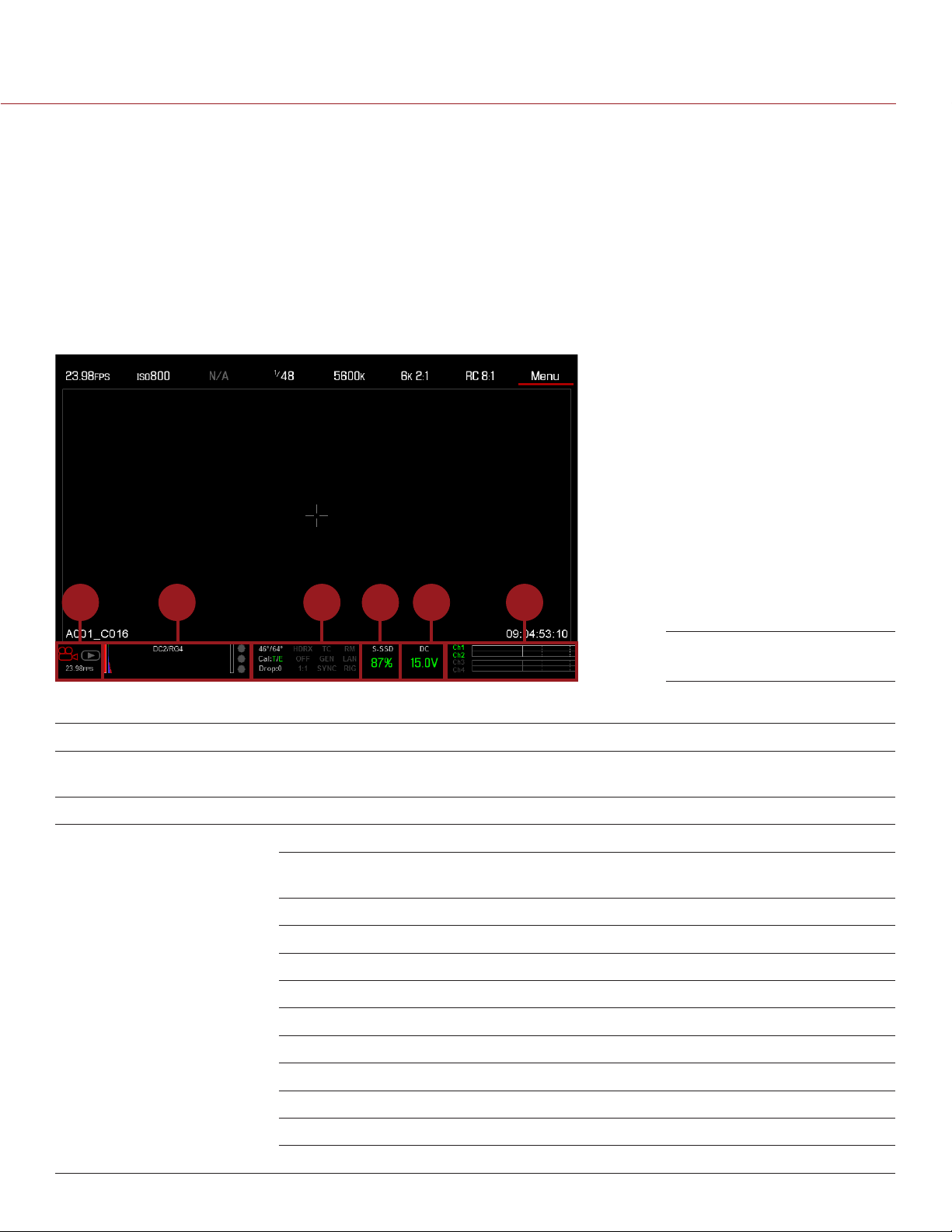
EPIC/SCARLET OPERATION GUIDE
CANON AND NIKON LENSES
The camera displays the focal length and focal distance when a DSMC Canon Mount or a DSMC Nikon Mount
is installed and an electronically supported lens is attached. When AF is set to Manual or Confirm mode, the
focus distance displays as a pair of Near–Far distances. When in AF mode, a single estimated focus distance
displays.
The focal length and focal distance values and range vary depending on the attached lens. When the focal
length of the lens changes, the current values displays. For more information, go to “Lens Tab” on page 63.
LOWER STATUS ROW
The Lower Status Row provides access to key system information and camera values.
1 3 5 62
4
Lower Status Row: Motion
The Lower Status Row in Motion mode provides key system information and camera values, including:
# LOWER STATUS ROW ITEM SUB-ITEM/DESCRIPTION FOR MORE INFORMATION, GO TO...
1 Camera Mode Swipe up to toggle Motion/Stills/Playback
modes
2 Histogram Histogram; tap to access the Tools menu “Histogram” on page 56
3 System Status
Indicators
Tap to access the System Status menu “System Status” on page 96
Temperature: Camera sensor and core
temperature, respectively
Cal: T/E “CAL: T/E Indicator” on page 57
HDR: Displays when HDRx mode is on “HDRX Menu” on page 102
False Color Mode: Displays modes “False Color Modes” on page 54
Magnify: Tallies 1:1 if magnify is selected “Magnify” on page 56
Timecode “Timecode” on page 135
Genlock “GEN Indicator” on page 57
“Camera Mode” on page 55
“Sensor Calibration” on page 90
COPYRIGHT © 2016 RED.COM, INC
Sync “SYNC Indicator” on page 57
RM: Indicates link to REDMOTE “REDMOTE Operation” on page 146
LAN “LAN Indicator” on page 58
RIG: Indicates 3D rig metadata is present N/A
955-0020_V6.2, REV-J | 54
Page 55

EPIC/SCARLET OPERATION GUIDE
4 Media Status Media location and remaining media
capacity; tap to access the Media Menu
5 Power Status DC voltage in or % of remaining battery
capacity; tap to access the Power menu
6 Audio Meter Audio input selection and levels;
tap to access the Audio menu
“Media Menu” on page 96
“Power Status” on page 58
“Audio Meter Levels” on page 134
CAMERA MODE
The Camera Mode allows you to seamlessly toggle between Motion mode, Stills mode, and Playback. To select
a camera mode, select the Camera Mode icon in the Lower Status Bar, swipe up, and select a camera mode.
NOTE: Setting adjustments made in Stills mode do not affect the settings in Motion mode, and vice versa.
NOTE: You can also switch between Stills and Motion mode by using the Motion/Stills switch on the DSMC Side
Handle and REDMOTE.
You can select the following camera modes:
“Motion Mode” on page 55
“Stills Mode” on page 56
“Playback Menu” on page 97
MOTION MODE
Motion mode optimizes your camera settings for capturing motion. This mode defaults the camera to Continuous
Record. Motion mode includes the following features:
Motion recording modes:
‒ “Continuous Record” on page 73
‒ “Internal Timelapse Timer” on page 73
‒ “Frame Trigger” on page 73
‒ “Speed Ramp Mode” on page 74
‒ “REDCODE Burst” on page 74
Swipe-Up Shortcuts
‒ Camera Mode
‒ Tools
‒ Media
‒ Power
NOTE: For more information, go to “Swipe-Up Menu” on page 60.
Default Motion Preset (RED)
NOTE: For more information, go to “Default Key Functions” on page 188.
COPYRIGHT © 2016 RED.COM, INC 955-0020_V6.2, REV-J | 55
Page 56
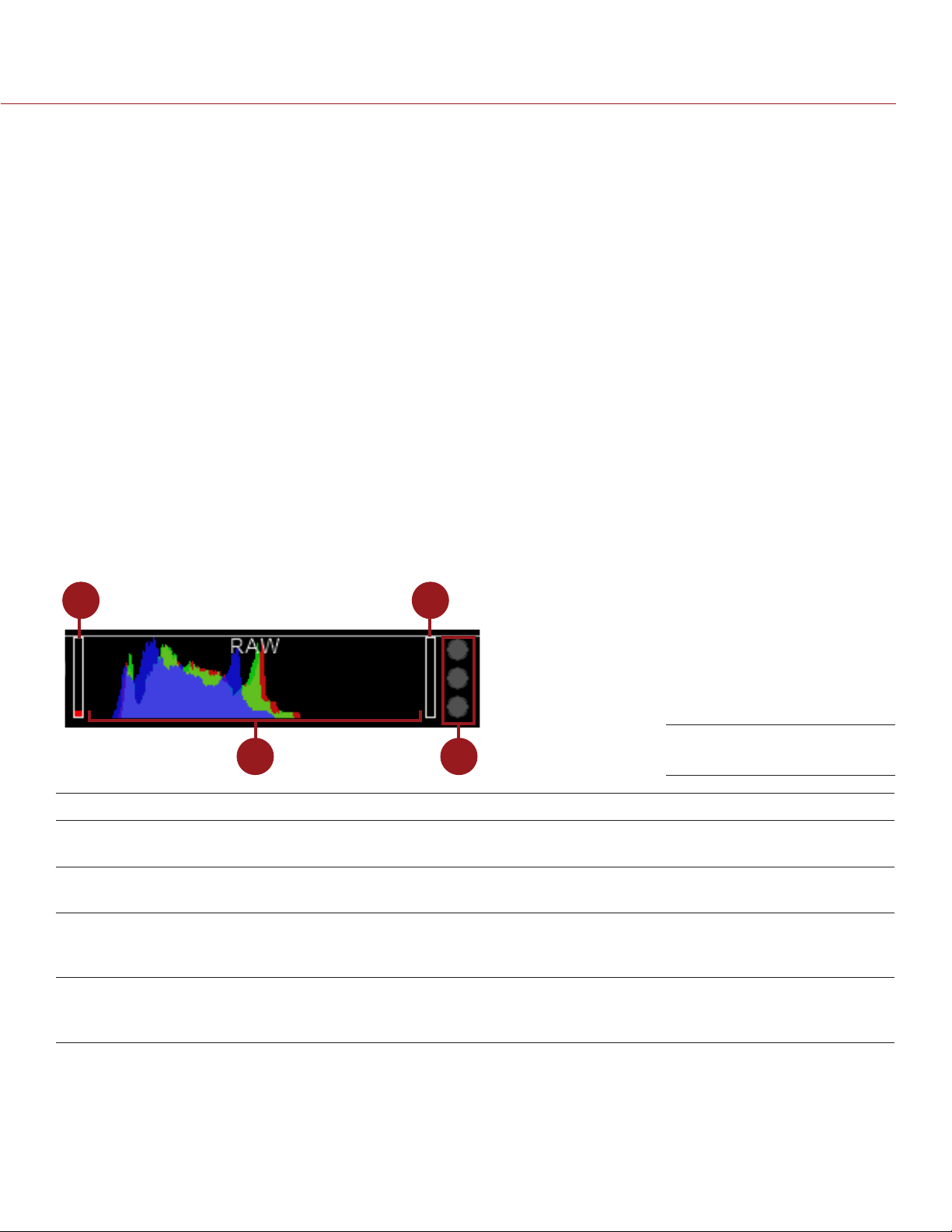
EPIC/SCARLET OPERATION GUIDE
STILLS MODE
Stills mode optimizes your camera settings for capturing stills. In Stills mode, the camera defaults to 6K 3:2,
REDCODE 3:1, Auto Exposure Single Shot, and Multi-Shot mode. Stills mode includes the following features:
Stills recording modes:
‒ “Multi-Shot” on page 75
‒ “Motion + Stills” on page 76
Swipe-Up Shortcuts:
‒ Auto Exposure
‒ Auto Focus
‒ Record Mode
NOTE: For more information, go to “Swipe-Up Menu” on page 60.
Default Stills Preset (RED)
NOTE: For more information, go to “Preset Default Key Functions” on page 219.
HISTOGRAM
This section describes the elements that comprise the Histogram section in the Lower Status Row. This section
of the GUI helps ensure that recorded footage is properly exposed.
Tap the Histogram in the Lower Status Row to access the Tools menu. For more information, go to “Tools” on
page 54.
1
3
# ITEM DESCRIPTION
1
1 RAW Level Bar (left)
2 RAW Level Bar (right)
3 RGB Histogram Provides a visual representation of exposure and sensor data levels for Red,
4 RAW Clip Meter Also known as “traffic lights”. Provides a visual representation of exposure and
1. The RAW Level Bars display the amount of pixels in the image that are noisy or clipped in relation to the total number of pixels in the
image. For example, if the left RAW Level Bar is 1/8 of the total height, that means that approximately 1/8 of the total pixels in the total
image are at an exposure level that is at risk of displaying noise when pushed to higher ISO or FLUT® values in post production.
Also known as a “goal post”. Displays the amount of pixels in the image that
are underexposed (noise)
1
Also known as a “goal post”. Displays the amount of pixels in the image that are
overexposed (clipping)
Green, and Blue channels; meter is affected by White Balance, ISO, and VIEW/
LOOK settings
sensor data levels for Red, Green, and Blue channels; Circles (traffic lights) will
light up when clipping occurs
2
4
Histogram (Exposure)
COPYRIGHT © 2016 RED.COM, INC
955-0020_V6.2, REV-J | 56
Page 57

EPIC/SCARLET OPERATION GUIDE
SYSTEM STATUS INDICATORS
This section describes the colors and behavior of the System Status indicators in the Lower Status Row. Tap
the System Status indicators in the Lower Status Row to access the System Status menu. For more information,
go to “System Status” on page 96.
CAL: T/E INDICATOR
The CAL: T/E indicator shows changes to temperature (T) or exposure (E) in relation to the active calibration
map. If the temperature or exposure change significantly, black shade the camera at the desired temperature
and exposure. Failure to properly calibrate the sensor may reduce image quality.
Green: Sensor temperature or exposure are properly calibrated for current settings.
Yellow: Slight change in sensor temperature or exposure.
Red: Significant change in sensor temperature or exposure.
The – and + indicate whether the sensor temperature or exposure has decreased or increased, respectively.
NOTE: T and E indicators change colors independently of each other.
TC INDICATOR
The TC indicator shows the current timecode status.
Grey: No analog timecode is detected.
Red: Analog timecode is detected but not enabled.
Green: Analog timecode is used to jam the time of day timecode.
For more information, go to “Timecode, Genlock, Multi-Camera Setup” on page 135.
GEN INDICATOR
The GEN indicator shows the current genlock status.
Grey: No genlock signal is detected, or the signal cannot cross-lock to project (24.00 fps vs. 23.98 fps).
Red: During process of sync, or genlock is lost while recording.
Green: A genlock signal matching the current HD-SDI monitor rate is locked.
Yellow: Timing is cross-locked to compatible but not matching monitor rate. For example, genlock is 24.00
fps, and HD-SDI monitor rate is 25.00 fps.
NOTE: When the GEN indicator is yellow, DO NOT perform 3D operation. This warns that genlock source
settings and camera settings are not aligned, so phasing of the sync between cameras is not guaranteed.
For more information, go to “Timecode, Genlock, Multi-Camera Setup” on page 135.
SYNC INDICATOR
The SYNC indicator shows the current sensor sync status, based on genlock.
Grey: The sensor sync mode is not set to genlock.
Red: The sensor sync mode is set to genlock, but is not locked to a genlock signal. This may occur if
genlock or sensor sync is lost while recording.
Green: The sensor sync mode and HD-SDI monitor rate are locked to a compatible genlock signal.
For more information, go to “Timecode, Genlock, Multi-Camera Setup” on page 135.
COPYRIGHT © 2016 RED.COM, INC 955-0020_V6.2, REV-J | 57
Page 58

EPIC/SCARLET OPERATION GUIDE
LAN INDICATOR
The LAN indicator shows the current status of an external LAN connection through the Gig-E port.
Grey: External control of the camera is not enabled.
Yellow: If the LAN indicator is yellow, external camera control is not possible. For more information, go to
“Cannot Control Camera Externally” on page 149.
NOTE: The Yellow LAN indicator only applies to EPIC-X MYSTERIUM and EPIC-M MYSTERIUM-X.
Green: Ethernet is enabled.
POWER STATUS
The Power Status element displays the current supply voltage or remaining battery capacity. Tap the Power
Status element to access the Power menu. For more information, go to “Power Menu” on page 101.
DC IN SUPPLY VOLTAGE
When powering the camera via DC power, the current voltage displays. When powering the camera using
batteries, the remaining battery capacity displays. The remaining capacity is indicated by the following colors:
Green: 12.0 V and up
Yellow: 11.8 V to 11.9 V
Red: 11.6 V to 11.7 V
NOTE: The camera turns off automatically if the supply voltage drops to 11.5 V.
BATTERY TIME REMAINING
When using a REDVOLT or REDVOLT XL battery, the power status displays the location of the power source
(example: SH: DSMC Side Handle; RM: Rear Module) and the remaining battery capacity. When using a RED
BRICK battery connected to DC IN, the power status displays BRICK and the remaining battery capacity.
The color of the displayed battery capacity represents the amount of time remaining:
Green: >10 minutes
Yellow: 5 to 10 minutes
Red: <5 minutes
COPYRIGHT © 2016 RED.COM, INC
955-0020_V6.2, REV-J | 58
Page 59
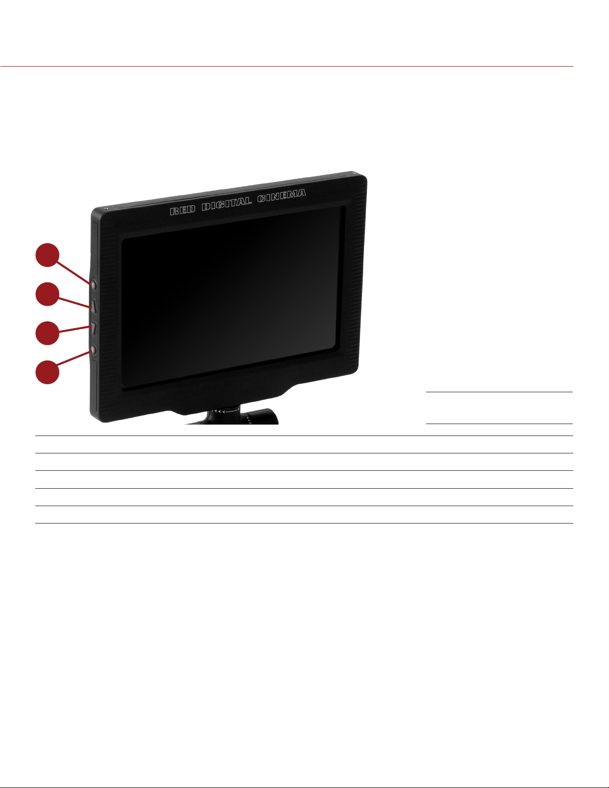
EPIC/SCARLET OPERATION GUIDE
NAVIGATION CONTROLS
This section describes basic controls for navigating the camera menus.
TOUCHSCREEN NAVIGATION
RED Touch displays offer intuitive menu control and four (4) programmable buttons.
1
2
3
4
RED Touch 7.0" LCD
# RED TOUCH BUTTON DESCRIPTION
1 User Key 1 Toggle 1:1 Magnify on/off
2 Up Button Increase display brightness
3 Down Button Decrease display brightness
4 User Key 2 Toggle Exposure Mode on/off
NOTE: RED Touch display keys are programmable. For more information, go to “Key Mapping” on page 80.
Navigate the menus using a touchscreen by using the following gestures:
Tap: Tap has many functions:
‒ Tap to select a Basic Menu, submenu, or button.
‒ If a menu is open, tap anywhere outside the menu to save any changes and close the menu.
‒ Tap the right or left regions of the touchscreen to access the programmable soft keys.
Swipe: Swipe to select different values in spinners or drop-down menus. For more information, go to
“Swipe-Up Menu” on page 60.
Double-Tap: If the monitor is in Clean mode, changes to Overlay mode.
Hold: Tap and hold an icon to bring up an advanced interface display.
Pinch: Move two (2) fingers apart/together to increase/decrease the size of the image. By default, this
gesture is disabled.
For more information, go to “Gestures” on page 61.
COPYRIGHT © 2016 RED.COM, INC 955-0020_V6.2, REV-J | 59
Page 60
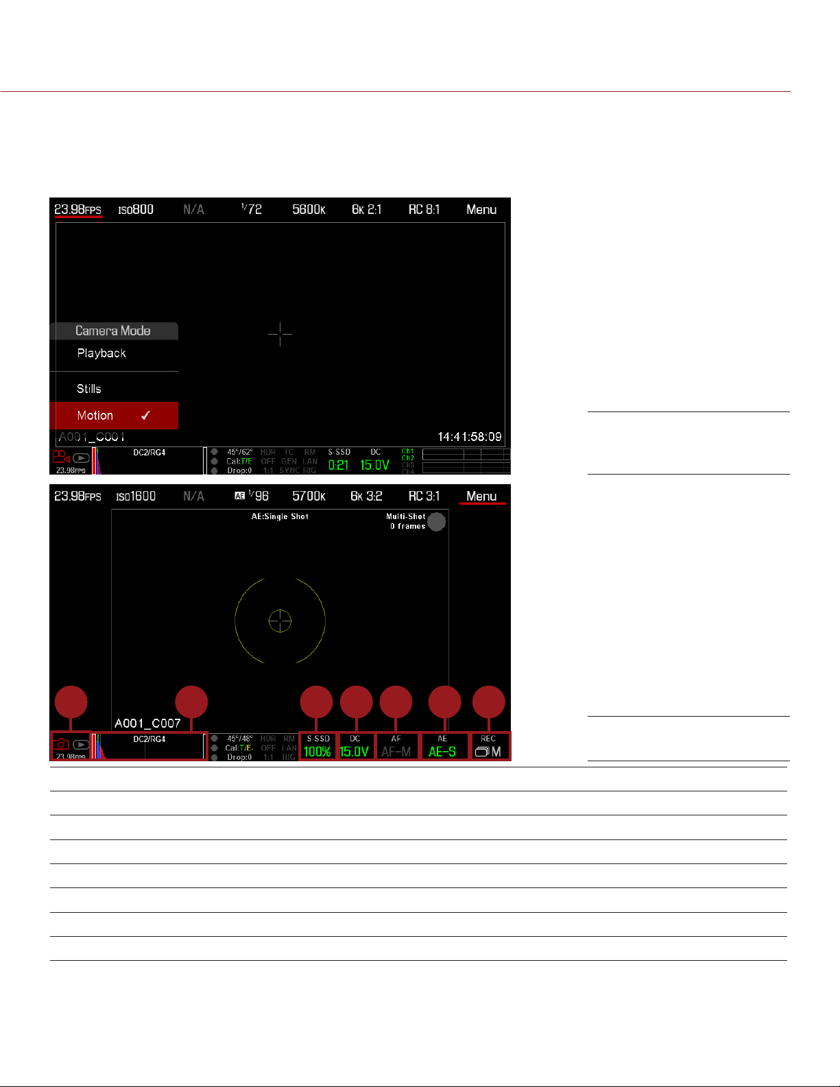
EPIC/SCARLET OPERATION GUIDE
SWIPE-UP MENU
The Swipe-Up Menu is available in the Lower Status Row on RED Touch displays and provides Swipe-Up
Shortcuts for Motion mode, Stills mode, and Playback.
For example, select the Camera Mode icon in the Lower Status Bar, swipe up, and select a Camera Mode.
Swipe Up to Select a
Camera Mode
1 42 3 5 6 7
Stills Mode
# SWIPE-UP SHORTCUT DESCRIPTION
1 Camera Mode
2 Tools Set Horizon, RAW, Magnify, Zebras, and False Color
3 Media View as Percentage or Time Remaining, eject media, view clip thumbnails
4 Power View as Percentage or Time Remaining
5 Auto Focus
6 Auto Exposure
7 Record Mode
1. For more information about Stills mode and Motion mode, go to “Camera Mode” on page 55.
2. Shortcuts only available in Stills Mode.
COPYRIGHT © 2016 RED.COM, INC
1
2
2
2
Select Playback, Motion, or Stills
Set Zone, Size, and Mode
Set Exp Comp, Speed, Metering, Priority, and Mode
Select Multi-Shot or Motion + Stills
955-0020_V6.2, REV-J | 60
Page 61
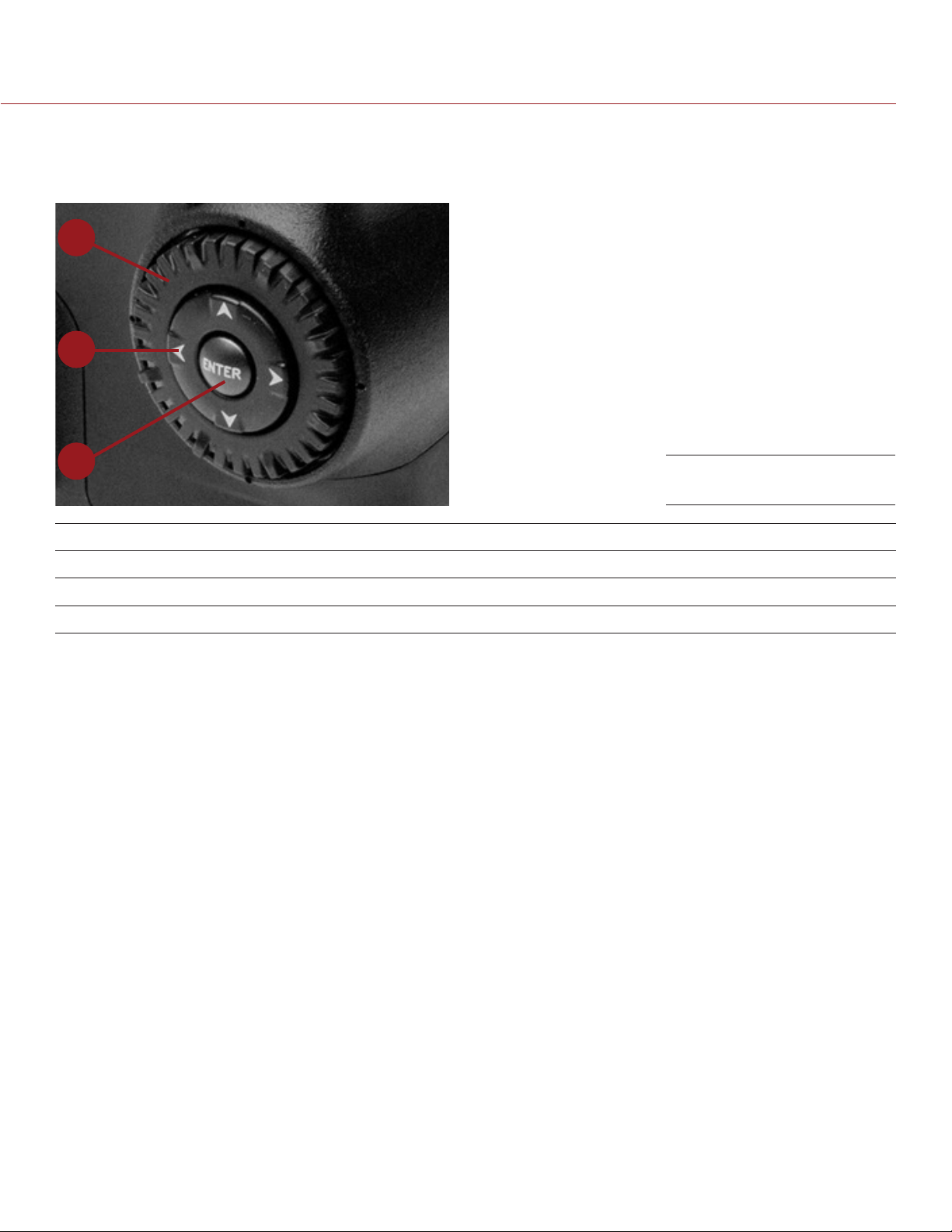
EPIC/SCARLET OPERATION GUIDE
NAVIGATION GROUP
The Navigation Group is the primary control interface on the DSMC Side Handle, RED Switchblade-M, and
REDMOTE
1
2
3
Navigation Group
# NAVIGATION GROUP ELEMENT DESCRIPTION
1 Scroll Wheel Select and adjust the value of a selected setting
2 Directional Keys (D-Pad) Navigate menus and menu items
3 ENTER key Press ENTER to confirm a setting or access the selected menu
Navigate the menus using a DSMC Side Handle, RED Switchblade-M, or REDMOTE using the following controls:
Press ENTER to open the menu, then rotate the Scroll Wheel clockwise to move right, counterclockwise to
move left to highlight the desired menu or parameter. Press ENTER to select.
Press the Up Navigation Key to open the related Advanced Settings menu, if one (1) is available.
For more information, go to “Default Key Functions” on page 188.
For more information on the REDMOTE, go to “REDMOTE Operation” on page 146.
COPYRIGHT © 2016 RED.COM, INC 955-0020_V6.2, REV-J | 61
Page 62
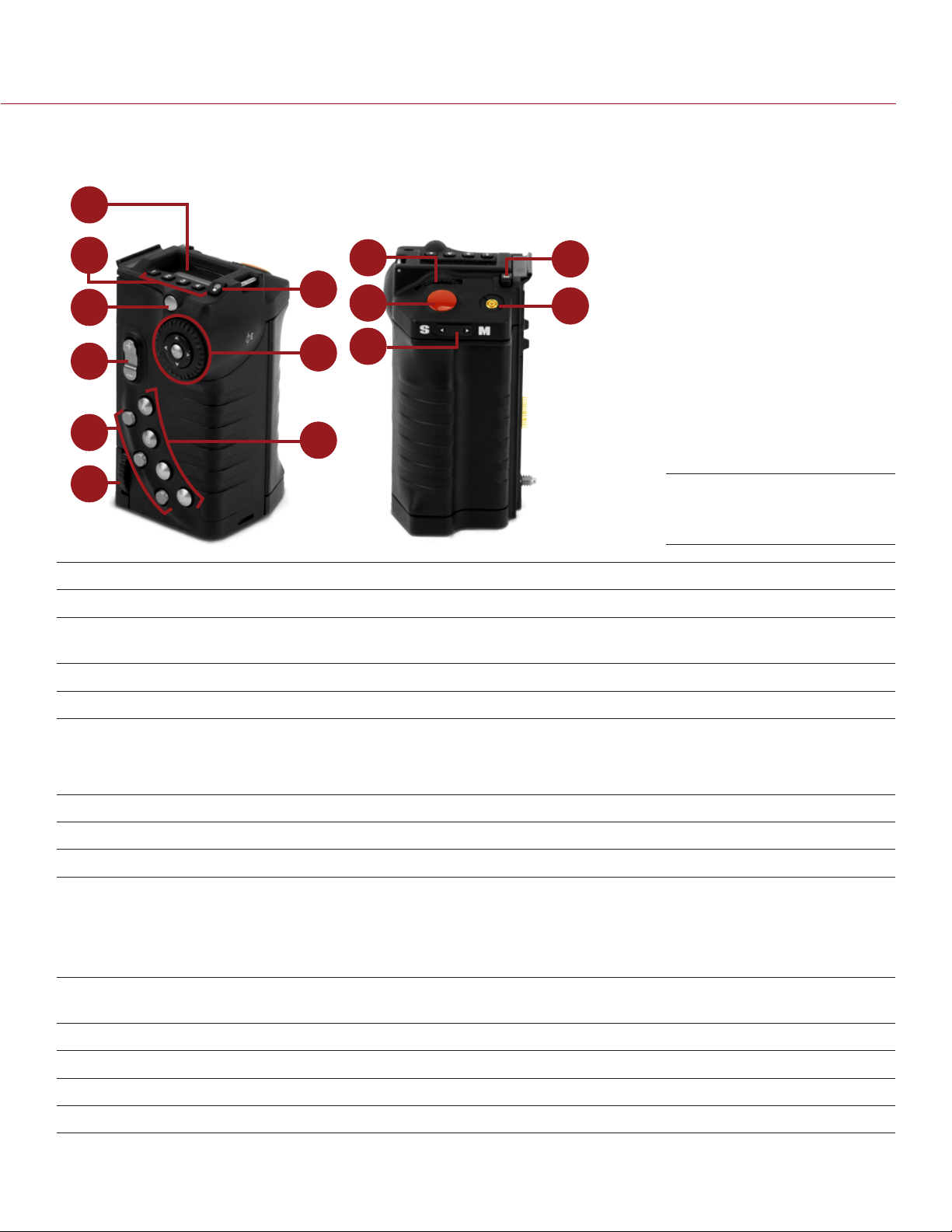
EPIC/SCARLET OPERATION GUIDE
DSMC SIDE HANDLE
This section describes the controls and display of the DSMC Side Handle.
1
2
10
13
7
3
4
5
11
12
8
9
14
6
# CONTROL/ITEM DESCRIPTION
1 LCD Display Go to “DSMC Side Handle Display” on page 63
2 User Keys (1–4)
3 Menu Button Access menus or exit currently selected menu
4 Rocker Switch Open (Up)/Close (Down) Iris
1
User 1-4 keys are used to select a slot on the DSMC Side Handle Display. The
front rotary then adjusts the value of the selected slot.
DSMC Side Handle
Controls
5 User Keys (5–7) 5: Toggle Exposure Mode on/off
6: Key Disabled
7: Eject Media
6 Thumbwheel Lock Install and remove the DSMC Side Handle
7 LCD Backlight Button Toggles LCD backlight illumination
8 Navigation Group Navigate menus and menu items; go to “Navigation Group” on page 61
9 User Keys (A–D) A: Cycle Auto-Focus Mode
B: Auto White Balance
C: Toggle 1:1 Magnify on/off
D: Toggle Exposure Mode on/off
10 Rotary Dial Adjust camera parameter values based on the underlined value on the
DSMC Side Handle LCD Display
11 Focus/Record Button Half-press for auto-focus; full press to Start/Stop Record
12 Stills/Motion Mode Switch Toggles between Stills/Motion Mode, enabled in v6.0 firmware or later
13 Battery Door Release Press to open the battery door
14 PC Sync Port Triggers external flashes or strobes
1. Press User Keys 1 + 4 simultaneously to lock/unlock DSMC Side Handle buttons to prevent inadvertent menu changes.
NOTE: DSMC Side Handle keys are programmable. For more information, go to “Key Mapping” on page 80.
COPYRIGHT © 2016 RED.COM, INC
955-0020_V6.2, REV-J | 62
Page 63
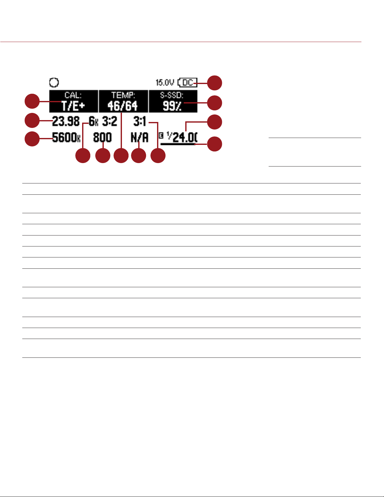
EPIC/SCARLET OPERATION GUIDE
DSMC SIDE HANDLE DISPLAY
The DSMC Side Handle displays Basic Menu parameters and other system status information.
12
1
2
11
10
3
9
4
The DSMC Side Handle displays the following camera parameters:
# DISPLAY ITEM DESCRIPTION
1 Calibration Indicator of relative change in sensor temperature and exposure since
2 Recording Frame Rate Current recording frame rate
3 White Balance Color temperature
4 Resolution Recording resolution
5 ISO Camera sensor sensitivity
6 Temperature Displays camera sensor and core temperature, respectively
7 Lens Information Displays aperture when a supported Canon, Nikon, or Cooke lens is
5
7
6
last calibration
attached
8
DSMC Side Handle
Display
8 REDCODE REDCODE compression setting
9 Cursor User 1-4 keys are used to move the cursor to select a slot. The front rotary
then adjusts the value of the selected slot.
10 Shutter Speed Integration time or shutter angle
11 Media Status Displays media location and remaining media capacity
12 Power Status Indicates DC supply voltage or % of remaining battery capacity including
current supply voltage
COPYRIGHT © 2016 RED.COM, INC 955-0020_V6.2, REV-J | 63
Page 64
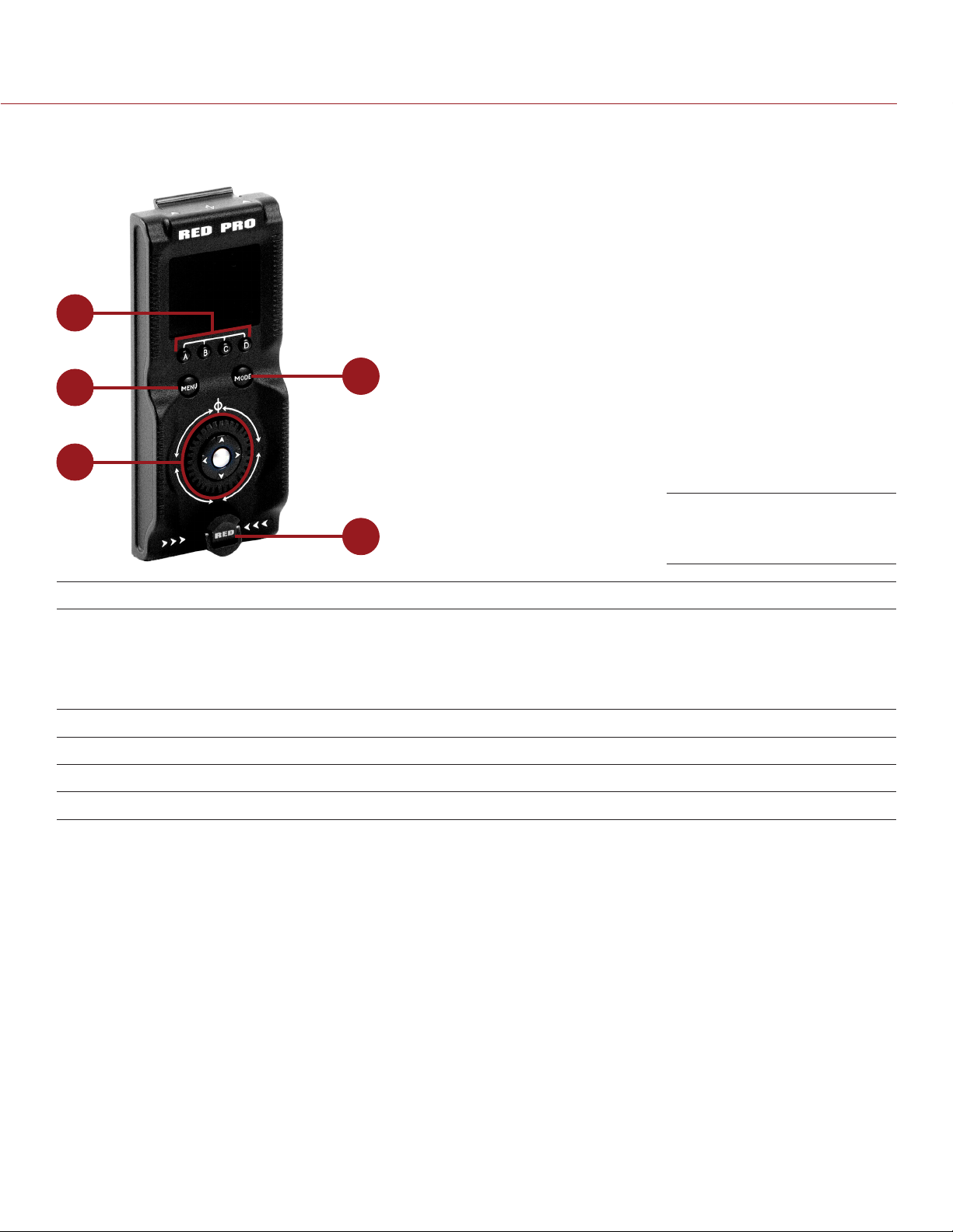
EPIC/SCARLET OPERATION GUIDE
RED SWITCHBLADE-M
This section describes the controls and display of the RED Switchblade-M.
1
2
3
4
RED Switchblade-M
5
# CONTROL/ITEM DESCRIPTION
1 User Keys (A–D)
2 MENU Button
3 MODE Button Toggle RED Switchblade-M between Remote and Local Modes
4 Navigation Group Navigate menus and menu items; Go to “Navigation Group” on page 61
5 Mounting Thumbscrew Install and remove the RED Switchblade-M
1. Press User Keys A + D simultaneously to lock/unlock RED Switchblade-M buttons to prevent inadvertent menu changes.
2. MODE Button functionality requires camera firmware v5.3 or later.
NOTE: RED Switchblade-M keys are programmable. For more information, go to “Key Mapping” on page 80.
1
2
A: Cycle Auto-Focus Mode
B: Auto White Balance
C: Toggle 1:1 Magnify
D: Toggle Exposure Mode
Access menus or exit currently selected menu
Controls
OPERATION MODES
The RED Switchblade-M OLED display reflects the currently selected mode. Use the Scroll Wheel and Directional
Keys to navigate menus. Press MENU to access the Advanced Menu.
Press MODE to toggle between the following modes:
Remote Mode: Navigate with RED Switchblade-M controls, using an attached LCD, EVF, or other monitor as
a reference. The RED Switchblade-M displays the primary control screen.
Local Mode: Navigate using the RED Switchblade-M controls and display. User Keys A-D are inactive.
KEY LOCK/UNLOCK
Lock the keys on the RED Switchblade-M to prevent inadvertent button presses and menu changes.
Lock: Press A + D simultaneously.
Unlock: Press A + D simultaneously. Alternatively, press and hold ENTER while keys are locked.
COPYRIGHT © 2016 RED.COM, INC
955-0020_V6.2, REV-J | 64
Page 65
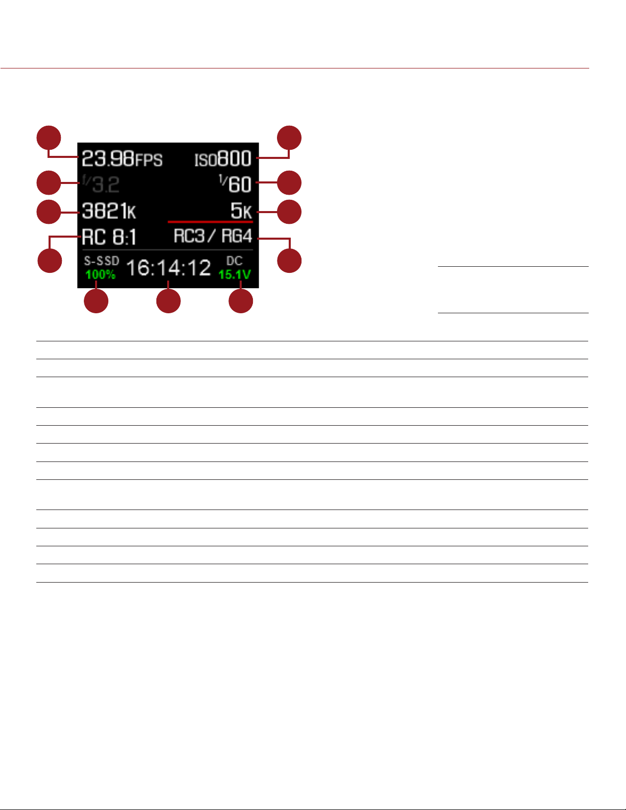
EPIC/SCARLET OPERATION GUIDE
RED SWITCHBLADE-M DISPLAY
The RED Switchblade-M OLED display provides basic camera parameters during operation.
1
2
3
4
5 6 7
The RED Switchblade-M displays the following camera parameters:
# DISPLAY ITEM DESCRIPTION
1 Frame Rate Current Recording Frame Rate
2 Lens Information Displays aperture when a supported Canon, Nikon, or Cooke lens is
attached
3 White Balance Color temperature
4 REDCODE REDCODE compression setting
11
10
9
8
RED Switchblade-M OLED
(Local Mode)
5 Media Status Displays media location and remaining media capacity
6 Timecode Current timecode value
7 Power Status Indicates DC supply voltage or % of remaining battery capacity including
current supply voltage
8 Color and Gamma Space Currently selected RED color and gamma space settings
9 Resolution Recording resolution
10 Shutter Speed Integration time or shutter angle
11 ISO Camera sensor sensitivity
725-0003
COPYRIGHT © 2016 RED.COM, INC 955-0020_V6.2, REV-J | 65
Page 66
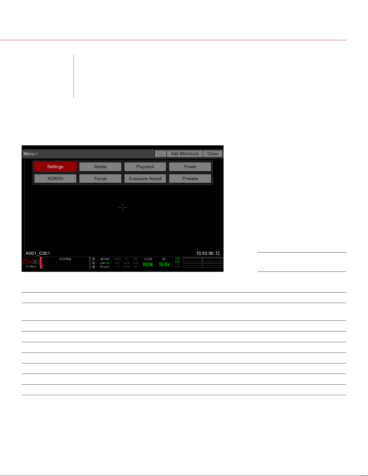
EPIC/SCARLET OPERATION GUIDE
ADVANCED
05
MENUS
ADVANCED MENUS
Advanced Menu
b nvvb
The Advanced Menus include:
ADVANCED MENU DESCRIPTION FOR MORE INFORMATION, GO TO...
Settings Camera settings including: Display, Look, Project,
Audio, Recording, Setup, and Maintenance
Media SSD operations including: format, eject, and more “Media Menu” on page 118
Playback View clips recorded to the attached SSD “Playback Menu” on page 119
Power Power sources, settings, status, and shutdown “Power Menu” on page 121
HDRX HDRx mode and settings “HDRX Menu” on page 123
Focus Focus modes, features, settings, and rack focus “Focus Menu” on page 124
Exposure Assist Automatic exposure settings and controls “Exposure Assist” on page 129
Presets Adjust Looks, key mappings, I/O, and more “Presets Menu” on page 131
“Settings Menu” on page 67
ACCESS THE ADVANCED MENUS
Tap the Menu button on the DSMC® Side Handle or REDMOTE® .
Tap the Menu icon on the touchscreen.
Select the Advanced... button in any menu from the Upper Status Row.
COPYRIGHT © 2016 RED.COM, INC
955-0020_V6.2, REV-J | 66
Page 67
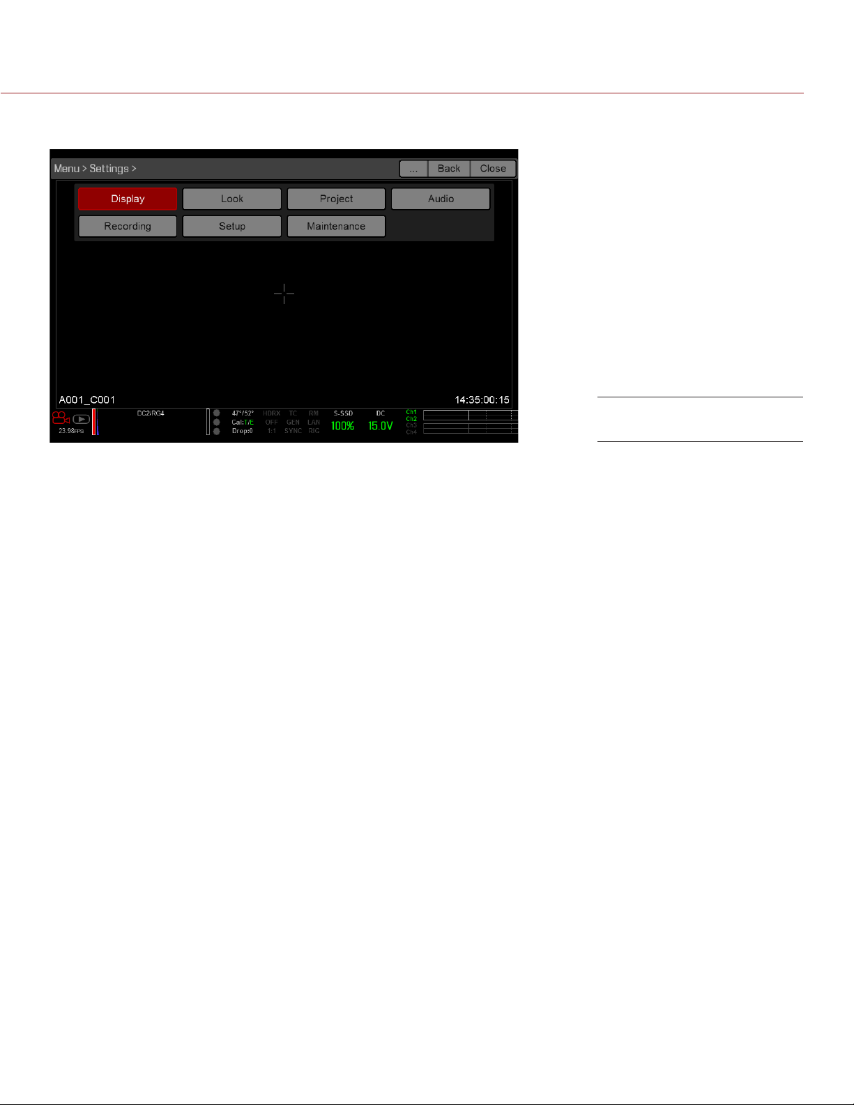
EPIC/SCARLET OPERATION GUIDE
SETTINGS MENU
Settings Menu
The Settings menu includes: Display, Look, Project, Audio, Recording, Setup, and Maintenance.
DISPLAY
The Display menu includes: Tools, Zebra, Monitor Control, Modes, Guides, Test Signal, and REDCAST™ (the
REDCAST menu is only accessible when a REDCAST Module is installed).
TOOLS
The Tools menu provides access to false color and display modes.
For more information, see the Exposure with RED Cameras: False Color & Zebra Tools article, available at www.
red.com/learn/red-101/exposure-false-color-zebra-tools.
FALSE COLOR MODES
False color modes include: Off, Exposure, Video, Focus, Edge, and Gio Scope.
NOTE: Only monitors with the Tools check box selected in the Monitor Control menu show the false colors. For
more information, go to “Motor Control” on page 104.
NOTE: False color modes affect video recorded through HDMI® or HD-SDI to an external recorder if the Tools
check box is selected in the Monitor Control menu. When recording through HDMI or HD-SDI, use false color
modes only to help configure project settings, and then disable the mode before recording.
OFF
Disables all false color modes.
EXPOSURE
Displays color overlay on top of a desaturated image that allows you to check for proper exposure. When
enabled, the “E√” indicator displays in the Lower Status Row.
The Exposure meter colors indicate the following information:
Purple: Underexposed; indicates sensor exposure levels that may be noisy if gained up in post production.
Green: IRE 41–48; based on the RGB levels of the video out signal and not the RAW data.
Red: Overexposed; indicates sensor exposure levels that are clipping.
Purple (underexposure) and red (overexposure) are based on RAW data and show areas that are clipping or
close to clipping. The RGB settings (settings in the Look menu) DO NOT affect the Exposure indicators.
COPYRIGHT © 2016 RED.COM, INC 955-0020_V6.2, REV-J | 67
Page 68

EPIC/SCARLET OPERATION GUIDE
VIDEO
Displays a color overlay that indicates the video level of the RGB monitor path (calibrated to the SMPTE test
signal). When enabled, the “V√” indicator displays in the Lower Status Row.
Colors are based on the RGB levels of the video out signal (that is, the “cooked” look, and not RAW data). The
RGB settings (settings in the Look menu) affect the Video indicators.
The Video indicators represent the following IRE values (at all other values, the desaturated image represents
the luminance value of the ISO adjusted image):
Purple: IRE 0–4
Blue: IRE 5
Teal: IRE 10–12
Green: IRE 41–48
Pink: IRE 61–70
Straw: IRE 92–93
Yellow: IRE 94–95
Orange: IRE 96–98
Red: IRE 99–100
FOCUS
Emphasizes contrast and edges in the image without changing brightness or image content making it easier to
judge focus. Adjust zoom and focus to easily see which objects are coming into focus. When enabled, the “F√”
indicator displays in the Lower Status Row.
EDGE
Shows the edges/outlines of objects that are in focus. When enabled, the “F√” indicator displays in the Lower
Status Row.
NOTE: The Edge setting may interfere with recordings done via HDMI or HD-SDI in Clean mode.
GIO SCOPE
Displays a color overlay on top of a desaturated image, identifying the 16 stops of light within the full dynamic
range of the RED DRAGON® sensor.On cameras with the MYSTERIUM-X® sensor, you can still select up to 16
stops. However, the camera will not detect the top and bottom stops.
When enabled, the “G√” indicator displays in the Lower Status Row. The Gio Scope indicators are based on
RAW data. The RGB settings (settings in the Look menu) DO NOT affect the indicators.
Each number indicates a different stop of light.
11: Represents mid-grey.
16: Represents the top stop, and is broken up into 1/8th increments to show highlight roll-off. Each 1/8th
stop is represented by a different shade of red, ranging from light red (less light) to dark red (most light).
DISPLAY MODES
Display mode options include: Magnify, RAW, and Horizon.
COPYRIGHT © 2016 RED.COM, INC
955-0020_V6.2, REV-J | 68
Page 69

EPIC/SCARLET OPERATION GUIDE
MAGNIFY
Displays the central region of the sensor in 1:1 pixel resolution. When enabled, the 1:1 text in the Lower Status
Row turns green, and the AF Window and the magnified region display. The AF Window determines the center
point of the magnified region. If the lens or lens mount is not capable of autofocus with the camera, use Confirm
mode to turn on the AF Window. Sharpening is disabled when 1:1 magnify is enabled. The camera automatically
exits magnify mode when recording begins.
The Magnify tool magnifies a 1920 x 1020 region, centered on a 1920 x 1080 display. If the resolution is lower
than 1920 x 1020, the image border cannot be magnified. Use the following equations to determine the area of
the image border that will not be magnified:
Border width: (1920 – W) / 2
Border height: (1020 – H) / 2
NOTE: Frame rate and resolution cannot be modified in Magnify mode.
RAW
When enabled, the camera displays images unaffected by the RGB settings (settings in the Look menu). RAW
affects the video recorded via HDMI or HD-SDI to an external recorder. RAW image parameters DO NOT affect
image metadata; the parameters only affect the monitor output. The word RAW displays in the Histogram in the
Lower Status Row.
The RAW image parameters are:
Color Space: REDcolor2
Gamma Space: REDlogFilm
White Balance: 5600K
ISO: 800 ISO
Tint: 0 Tint
NOTE: In RAW mode, the following controls are disabled on all cameras: color temperature, tint, saturation,
RGB gains, ISO, contrast, brightness, shadow, flut, exposure compensation, LGG controls, RGB curves, and
luma curve.
HORIZON
Displays an overlay that provides a reference to the position of the horizon. The Horizon overlay consists of two
(2) short side-bars that are always horizontally centered on the monitor, and a single longer horizon-line that
adjusts to the horizon based on the orientation of the camera.
The side-bars are green if the pitch is within +/– 1° of the calibrated zero position, otherwise they are red. The
horizon-line is green if the roll is within +/– 1° of the calibrated zero position, otherwise it is red.
To add numerical values for the pitch and roll to the Horizon overlay, follow the instructions below:
1. Go to Menu > Settings > Display > Monitor Control > Overlay.
2. Select Create..., Clone..., or Edit..., respectively, for the desired overlay action.
3. Select a location on the interface to add the numerical data for the Horizon overlay.
4. Select Motion: Gyro Data (GYRO) from the Item drop-down menu.
5. Select the desired text size.
6. Select Add.
7. Select Save.
8. Go to Menu > Settings > Display > Monitor Control > Monitor, and select the overlay from the Overlay drop-
down menu.
NOTE: The internal gyroscope and accelerometer must be calibrated for the Horizon overlay to function properly.
For more information, go to “Gyroscope and Accelerometer Calibration” on page 107.
COPYRIGHT © 2016 RED.COM, INC 955-0020_V6.2, REV-J | 69
Page 70

EPIC/SCARLET OPERATION GUIDE
ZEBRA
Use Zebra mode to enable and adjust the upper and lower values for two (2) independent zebra indicators. Use
Zebra 1 for highlight exposure, and use Zebra 2 for mid-tones or shadows. Zebras are visible in Magnify mode
and are disabled by default.
The camera offers two (2) zebra types:
Video: IRE-based mode; evaluates based on the current ISO and Look settings, and not the RAW image.
RAW: Evaluates based on the RAW image.
For more information, see the Exposure with RED Cameras: False Color & Zebra Tools article, available at www.
red.com/learn/red-101/exposure-false-color-zebra-tools.
ENABLE ZEBRA INDICATORS
1. Go to Menu > Settings > Display > Zebra.
2. Select a Zebra check box.
‒ Zebra 1:
‒ Video: Areas of the image exposed within the IRE range are indicated by red diagonal lines at –45°.
Default is 98 to 100 IRE.
‒ RAW: Areas of the image exposed within the range of stops are indicated by solid red. Default is
15.80 to 16.00 stops.
‒ Zebra 2:
‒ Video: Areas of the image exposed within the IRE range are indicated by green diagonal lines at
45°. Default is 41 to 48 IRE.
‒ RAW: Areas of the image exposed within the range of stops are indicated by solid purple. Default
is 0.00 to 4.00 stops.
MONITOR CONTROL
Use the Monitor Control menu to configure monitor and overlay settings, control surface priorities, brightness,
and gestures.
MONITOR
Select the monitor to configure from the drop-down menu at the top of the menu. The other settings on the
menu are applicable to the selected monitor.
NOTE: Changes to Monitor Control settings take effect when you close the menu.
MODE
Determines the elements displayed on the monitor:
Clean: Only the video displays. The Upper Status Row, Lower Status Row, and overlays do not display.
Overlay: The overlay displays. Overlays include the Upper Status Row and the Lower Status Row.
Mirror: The monitor mirrors another screen at the same resolution. You cannot mirror a screen that is set
to Clean. The Mirror option is available based on the settings of the other attached monitors, and includes
the name of the monitor that can be mirrored.
NOTE: You can set a maximum of four (4) monitors to Overlay at a time. To assign additional monitors to Overlay,
mirror a monitor with the same resolution that is set to Overlay.
NOTE: When two (2) touchscreens are attached to the camera with the same resolution and one (1) is currently
the control surface, set the other to mirror it and give the effect of having two (2) control surfaces.
OVERLAY
Select which overlay shows on top of the video. RED® provides preset overlays, which have “(RED)” in the
overlay name. Create custom overlays in the Overlay tab. For more information, go to “Overlays” on page 72.
COPYRIGHT © 2016 RED.COM, INC
955-0020_V6.2, REV-J | 70
Page 71

EPIC/SCARLET OPERATION GUIDE
RESOLUTION
Select the output resolution for monitors (you cannot select a resolution for LCDs and EVFs, since the resolution
is determined automatically). For more information about available HD-SDI and HDMI resolutions, go to “3G-SDI
(HD-SDI) Out” on page 169 and “HDMI Out” on page 171.
FREQUENCY
Determines the monitor frequency. Available frequencies depend on the selected monitor. The LCD resolution
defaults to 60.00 Hz, which is the optimal refresh rate for the RED LCDs.
For HD-SDI monitors, the frequency depends on the project time base. For more information, go to “3G-SDI
(HD-SDI) Out” on page 169 and “HDMI Out” on page 171.
HD-SDI Auto: Sets the frequency equal to the Project Time Base, except when the Project Time Base is
47.95/48 fps. When the Project Time Base is 47.95/48 fps, the frequency is half that rate (23.98/24 Hz).
TOOLS
Enables the false color modes on the monitor. For more information, go to “Tools” on page 67.
UI FLIP/MIRROR
NOTE: This setting is NOT available on the RED Touch 7.0" LCD. For more information, go to “Flip/Mirror” on
page 71.
Flip the graphical user interface (GUI) vertically and mirror horizontally (not rotated). Use this setting when
mounting a monitor upside down. This setting only affects the monitor, and does not affect captured footage.
FLIP VIDEO
NOTE: This setting is NOT available on the RED Touch 7.0" LCD. For more information, go to “Flip/Mirror” on
page 71.
Flip footage horizontally, so that it is upside down. This setting only affects the monitor, and does not affect
captured footage.
FLIP/MIRROR
NOTE: This setting is ONLY available on the RED Touch 7.0" LCD.
Mirror and flip (invert) the graphical user interface (GUI) and footage, effectively rotating the entire displayed
image 180°. Use this setting when mounting a monitor or the entire camera rig upside down. This setting only
affects the monitor, and does not affect captured footage.
FRAMED OVERLAY
The video display is scaled down on the monitor so that the overlay items fit outside of the video area rather
than over it. This setting only affects the monitor, and does not affect captured footage.
AUTO HIDE MENUS
Hides the Upper Status Row and Lower Status Row. When this option is disabled, the video is scaled so that
the menus are not overlaid on the video. When this option is enabled, the video is not scaled. This option
creates a control surface on a monitor without scaling the video. This setting only affects the monitor, and does
not affect captured footage.
To toggle display/hide the menus when Auto Hide Menus is enabled, perform either of the following actions:
Press the Menu button on the DSMC Side Handle or RED Switchblade-M.
Tap the touchscreen.
NOTE: Enabling this option on a non-control surface results in the menus never displaying on that monitor.
COPYRIGHT © 2016 RED.COM, INC 955-0020_V6.2, REV-J | 71
Page 72
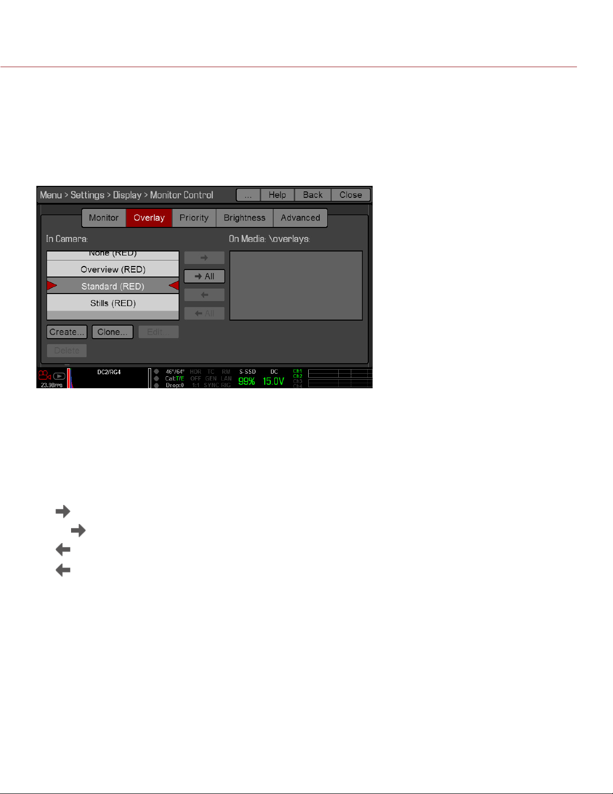
EPIC/SCARLET OPERATION GUIDE
OVERLAYS
Create custom overlays that include specific items. Overlays can be stored on the camera or transferred to SSD
to be shared with other cameras.
Camera: Overlays saved internally on the camera display in the Overlay drop-down menu on the Monitor
Control > Monitor tab.
Media: Overlays saved to an SSD can be found at On Media: \overlays:.
NOTE: Overlays that end with (RED) are provided by default and cannot be edited, deleted, or exported.
OVERLAY ACTIONS
Create...: Create a new custom overlay using a blank overlay template in the Overlay Editor.
Clone...: Create a new custom overlay using the selected camera overlay as a template in the Overlay Editor.
Edit...: Edit the selected camera overlay in the Overlay Editor.
Delete: Delete the selected camera overlay.
EXPORT AND IMPORT OVERLAYS
: Export selected overlay from camera to SSD.
All : Export all overlays from camera to SSD.
: Import selected overlay from SSD to camera.
All: Import all overlays from SSD to camera.
CREATE AND EDIT OVERLAYS
1. Go to Menu > Settings > Display > Monitor Control > Overlay.
2. Select Create, or select an existing overlay and select Clone or Edit.
3. If creating a new overlay, enter a name for the overlay and select OK.
4. Select any of the following check boxes to add the corresponding guides to the overlay:
‒ Frame Guide
‒ Action Guide
‒ Title Guide
5. Select a button on the matrix to add a user interface element to that position on the matrix.
By default, the Magnify indicator (MI) is on the top left, the Record indicator (REC) is on the top right, the
Clip Name (CLIP) is on the bottom left, and the Timecode (TC) is on the bottom right.
COPYRIGHT © 2016 RED.COM, INC
955-0020_V6.2, REV-J | 72
Page 73
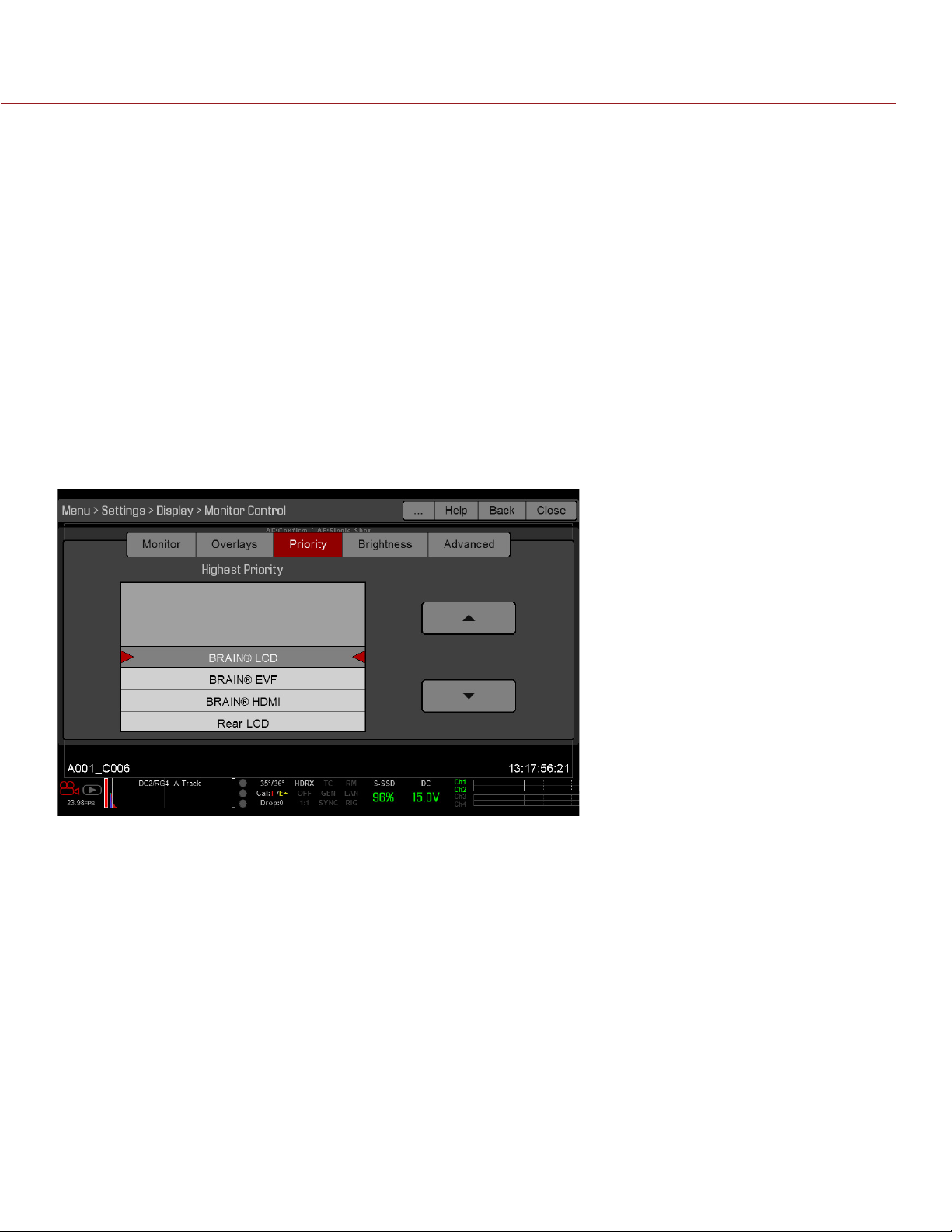
EPIC/SCARLET OPERATION GUIDE
6. Selecting one (1) of the buttons opens a new dialog that lets you choose a user interface element.
7. Select the Item that you want to add.
8. Select the Size of the item.
9. If adding a Custom Label (LBL), enter the Custom Text for that item.
10. Select Add to return to the previous screen.
11. Add all of the items to the overlay.
12. Select Create or Save.
The new overlay displays in the Camera list.
NOTE: Except for the Custom Label (LBL), you can only add each element once. If you add an element you have
already added to the overlay, the element moves to the new position.
LUTS
The LUTs menu is only accessible when a REDCAST Module is installed. For more information, see the REDCAST
Module Operation Guide, available at www.red.com/downloads.
PRIORITY
The camera can only have one (1) control monitor for interacting with camera settings. The Priority tab determines
the order in which a monitor becomes the control monitor. If you plan on removing or adding monitors during a
shoot, set up the priority list ahead of time.
For a monitor to become the control monitor, the following must occur:
The monitor must be set to Overlay mode in the Monitor Control menu.
Each monitor that has higher priority on the list must be either detached or not set to Overlay mode.
EXAMPLE
By default, the monitor priority is:
1. BRAIN LCD
2. BRAIN EVF
3. BRAIN HDMI
If you remove an LCD when an EVF is attached, then the EVF becomes the control monitor. If you then remove
the EVF when an HDMI monitor is attached, the HDMI monitor becomes the control monitor. If you then reattach the LCD, then the LCD is the control monitor again.
COPYRIGHT © 2016 RED.COM, INC 955-0020_V6.2, REV-J | 73
Page 74
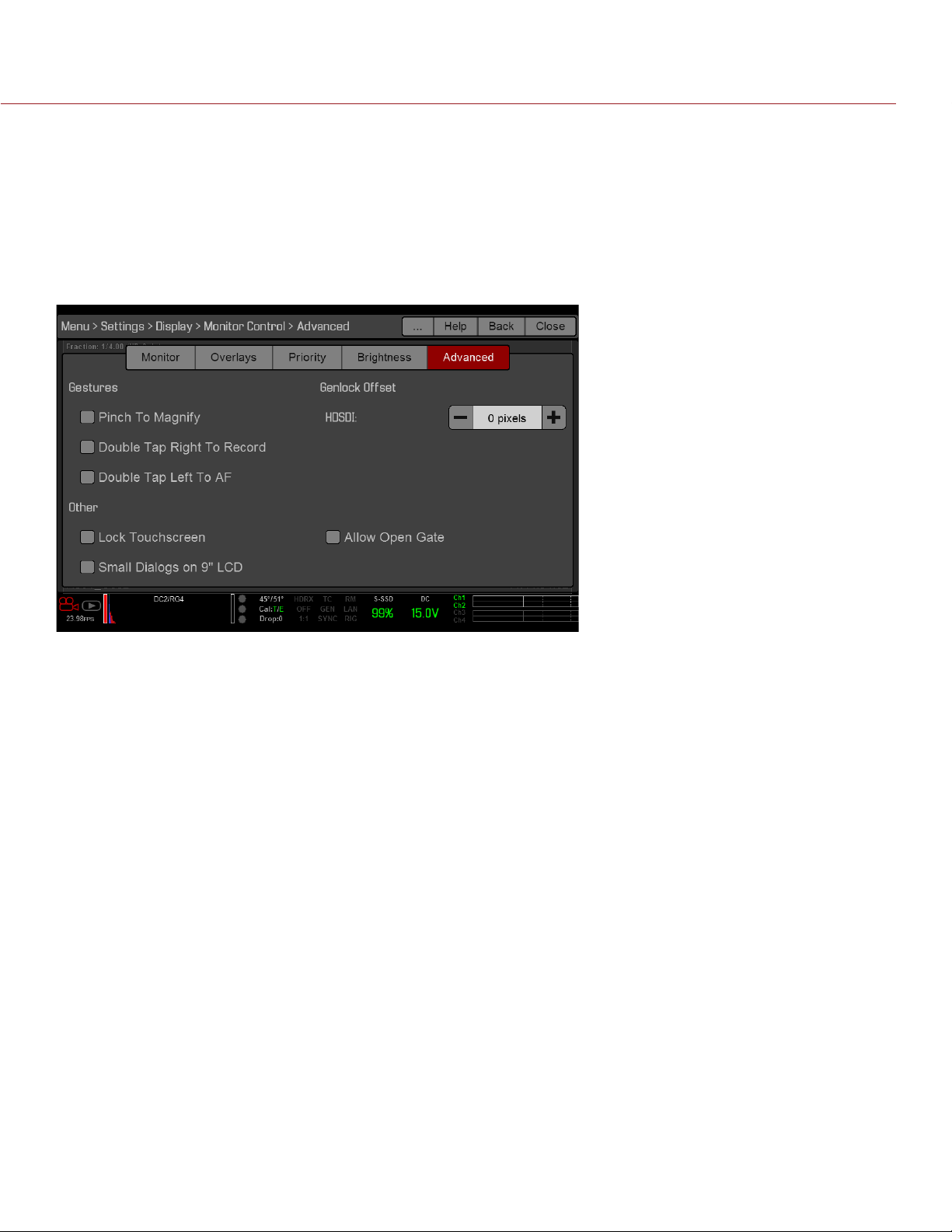
EPIC/SCARLET OPERATION GUIDE
BRIGHTNESS
Control the brightness of each LCD and EVF. Move to the right for a brighter display; move to the left for a
dimmer display. Side UI LCD controls the brightness of the Switchblade-M LCD.
NOTE: A rear LCD/EVF is an LCD/EVF that is plugged into any rear RED module, such as the +1 Adaptor Module
or the Pro I/O Module.
ADVANCED
Provides access to additional monitor settings.
GESTURES
Pinch to Magnify: Move two (2) fingers apart or together to toggle 1:1 Magnify. For more information, go to
“Magnify” on page 69.
Double-Tap Right 25% to Record: Double-tap the right 25% of the video area on the LCD to toggle record.
Double-Tap Left 25% to Start AF: Double-tap the left 25% of the video area on the LCD to start autofocus
when compatible lenses are used.
For a list of compatible lenses, go to “Lenses” on page 178.
OTHER
Lock Touch Screen: Touchscreen control is locked. To unlock, tap the screen and follow the on-screen
instructions.
Use Small Dialogs on 9" LCD: The dialogs on the RED Touch 9.0" LCD are smaller than the default dialogs.
GENLOCK OFFSET
Offset the video of the HDSDI out or REDCAST Module to align it with the genlock signal:
Negative offset: Advances the video, so the video reaches the switcher earlier than it would otherwise.
Positive offset: Advances the video, so the video reaches the switcher later than it would otherwise.
COPYRIGHT © 2016 RED.COM, INC
955-0020_V6.2, REV-J | 74
Page 75
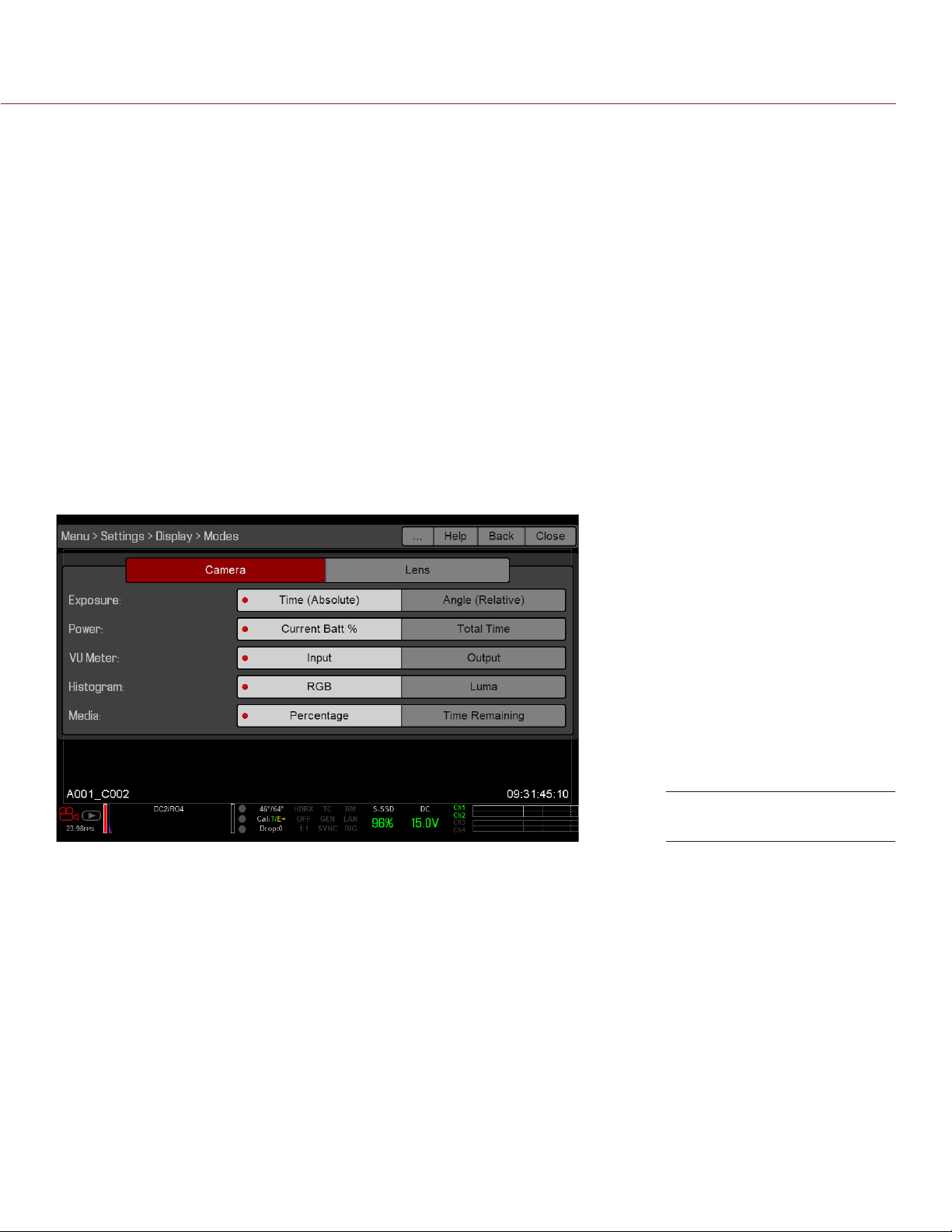
EPIC/SCARLET OPERATION GUIDE
ALLOW OPEN GATE
Open Gate allows the camera to preview images at a refresh rate that is twice the project time base. For
example, if the project time base is 23.98 FPS or 24.00 FPS, enabling Open Gate causes the LCD or EVF to
have a refresh rate of 48 Hz (50 Hz).
NOTE: You cannot use Open Gate when:
Varispeed is enabled.
Speed Ramp mode is enabled.
Genlock is enabled.
The shutter angle is 180° or greater.
NOTE: When you disable Open Gate mode, the image on the EVF may be disrupted for up to three (3) seconds.
MODES
Use the Modes menu to determine how the following settings display:
Camera
Lens
CAMERA TAB
Display Mode: Camera
EXPOSURE
Time (Absolute): Displays the exposure time in seconds (1/xx sec). When you change the frame rate in this
mode, the shutter time stays the same, but the shutter angle changes. Time (Absolute) is the default.
Angle (Relative): Displays the exposure as an angle (1–360°). When you change the frame rate in this mode,
the shutter angle stays the same, but the exposure time changes.
POWER
Current Batt %: Displays the remaining percentage of active battery. (Default)
Total Time: Displays the total run-time left of battery power, taking into account all available batteries.
VU METER
Input: Displays levels of audio inputs (pre-mixer). (Default)
Output: Displays levels of audio outputs (post-mixer).
COPYRIGHT © 2016 RED.COM, INC 955-0020_V6.2, REV-J | 75
Page 76
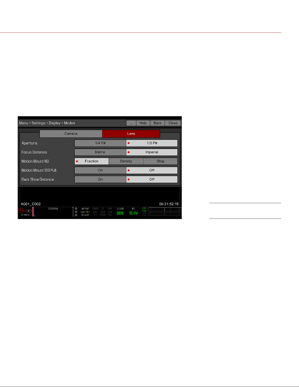
EPIC/SCARLET OPERATION GUIDE
HISTOGRAM
NOTE: The Histogram setting is not accessible on cameras with Monochrome or RED DRAGON Monochrome
sensors.
RGB: Displays red, green, and blue channels on histogram. (Default)
Luma: Displays luma channel on histogram.
MEDIA
Percentage: Displays media space remaining as a percentage. (Default)
Time Remaining: Displays media space remaining as time in hours and minutes (HHH:MM).
LENS TAB
Display Mode: Lens
APERTURE
1/4 F#: Aperture increments in 1/4 stops.
1/3 F#: Aperture increments in 1/3 stops. (Default)
FOCUS DISTANCE
Metric: Displays lens focus distances in meters.
Imperial: Displays lens focus distances in feet and inches. (Default)
MOTION MOUNT ND AND MOTION MOUNT ISO PULL
Only applicable when using a DSMC RED MOTION MOUNT®. For more information, see the RED MOTION MOUNT
Operation Guide, available at www.red.com/downloads.
RACK SHOW DISTANCE
On: Displays the focus distance of each rack point on the Live Action Area when rack focus is enabled. For
more information, go to “Set Up Rack Focus” on page 127.
Off: Does not display the focus distance of rack points when rack focus is enabled. (Default)
GUIDES
Use the Guides menu to configure the Frame Guide, Action Guide, and Title Guide.
COPYRIGHT © 2016 RED.COM, INC
955-0020_V6.2, REV-J | 76
Page 77

EPIC/SCARLET OPERATION GUIDE
MODE
Off: Disable all guides.
Full: Guide has the same aspect ratio as the record format.
4:3, 16:9, 1.85:1, 1.9:1, 2.4:1: Guide has the selected aspect ratio.
User: Select an aspect ratio from the drop-down menu that displays when you select this option.
Absolute: Guide is defined by absolute pixel dimensions rather than aspect ratio and scale. When you select
Absolute, the Width/Height fields replace the Scale field.
SCALE
Percentage to scale guide from its maximum possible size. Available range is 0–100%.
WIDTH/HEIGHT
The Width/Height fields replace the Scale field when you select Absolute from the Mode drop-down menu.
Select the values for the width and height of the guide in pixels.
OFFSET X/Y
Percentage to offset guide from its default centered position. Available range is 0–100%.
100%: Right-aligned (for X offset) and bottom-aligned (for Y offset).
-100%: Left-aligned (for X offset) and top-aligned (for Y offset).
APPEARANCE
Line Style: Select one of the following line styles: Solid, Dashed, or Bracket.
Color: Select the color that has the highest contrast to the scene. The default is White.
Opacity: Set the guide opacity. Available options are 0%, 25%, 50%, 75% and 100%.
RELATIVE TO FRAME GUIDE
Select the Relative to Frame Guide check box to size and position the guide relative to (and have it bounded by)
the Frame Guide instead of the record format.
NOTE: The Relative to Frame Guide check box is available on the Action Guide and Title Guide tabs.
GENERAL TAB
Enable/Disable and select the location (Relative To), color, and opacity of the following elements:
Center: The center crosshair.
Grid: Rule-of-thirds grid.
Shading: The shaded region outside of the area of interest.
TEST SIGNAL
Use the Test Signal menu to replace the video monitor outputs with one of the following video test patterns:
Chip Chart
SMPTE Bars
Luma
To enable a test signal, select the test signal box. To exit, tap the touchscreen or press the Enter or Menu button
on the DSMC Side Handle or REDMOTE. If needed, enable an Audio Tone.
NOTE: Test signals are not recordable; they are provided to help align external HD-SDI and HDMI monitors.
COPYRIGHT © 2016 RED.COM, INC 955-0020_V6.2, REV-J | 77
Page 78

EPIC/SCARLET OPERATION GUIDE
REDCAST
The REDCAST menu is only accessible when a REDCAST Module is installed. For more information, see the
REDCAST Module Operation Guide, available at www.red.com/downloads.
LOOK
The Look menu includes: Color, Gain, ISO/FLUT, Sharpness, Curves, Video, Color Temperature, and LGG (Lift,
Gamma, Gain).
The Look settings affect the look of the monitor path, but do not affect the recorded RAW data.
COLOR
Saturation: Adjusts color saturation. Range is 0.0 (monochrome) to 4.0 (super color). Default is 1.0.
Contrast: Adjusts the overall contrast of the image. Range is –1.0 (flat) to 1.0 (max contrast). Default is 0.0.
Brightness: Adjusts brightness without crushing highlights. Available range is –10.0 to 10.0. Default is 0.0.
Exp Comp: Adjusts exposure compensation. Available range is –7.0 to 7.0. Default is 0.0.
NOTE: Saturation is disabled on all Monochrome cameras.
GAIN
Adjust the Red channel, Blue channel, and Green channel individually. The range for each is 0.0 (none of the
color) to 10.0, and the default for each is 1.0.
ISO/FLUT
Use the ISO/FLUT menu to adjust ISO, FLUT, and Shadow. For more information, see the following articles:
Exposure with RED Cameras: Strategy, available at www.red.com/learn/red-101/exposure-with-red-
cameras
ISO Speed Revisited, available at www.red.com/learn/red-101/iso-speed-revisited
ISO
Select the camera ISO rating. The sensitivity value increments in 1/3 stops. When the ISO rating is adjusted,
the camera logs the change as metadata and the monitor path reacts accordingly. Higher ISO values lead to
brighter images in the monitor path, and vice versa.
RED recommends setting the ISO to the default, then adjust the aperture, lighting, and ND filters to match. The
ISO can later be adjusted around one (1) stop for fine-tuning.
Range is ISO 250 to 12,800. Default is ISO 800.
NOTE: For Monochrome and RED DRAGON Monochrome, the default is ISO 2000.
FLUT
Floating Point Lookup Table (FLUT) is an exposure control exclusive to RED. FLUT works like a traditional
ISO setting, but can be fine-tuned in post production to any level of exposure precision. FLUT automatically
protects highlights and shadows, even when changed substantially.
The FLUT setting is expressed in terms of relative exposure value (EV), where each unit represents a 1-stop
change in midtone exposure level. Range is –8.0 to 8.0. Default is 0.0.
SHADOW
Shadow adjusts the toe value of the FLUT (the tone near black). Increasing the Shadow value raises the video
level of near blacks. Lowering the Shadow value crushes the video level of near blacks. Range is –2.0 to 2.0.
Default is 0.0.
COPYRIGHT © 2016 RED.COM, INC
955-0020_V6.2, REV-J | 78
Page 79

EPIC/SCARLET OPERATION GUIDE
SHARPNESS
Control the sharpness of each monitor output. Move to the left for a sharper image; move to the right for a less
sharp image.
CURVES
Define the individual curves for the Luma, Red, Green, and Blue channels. You can only adjust one (1) curve at
a time. Select Reset Curve to reset a curve.
NOTE: Luma is the only channel on cameras with Monochrome or RED DRAGON Monochrome sensors.
VIDEO
Use the Video menus to adjust the color space and gamma space for each monitor output. All settings in the
Video menus affect metadata only, and can be changed in REDCINE-X PRO®.
NOTE: Selecting options in the Video menu may make the menu lighter or darker. The camera applies the color
and gamma spaces after rendering the user interface, so changing these settings affects the user interface.
NOTE: RED recommends using the most recently released Color Space and Graded Gamma settings. Use
legacy settings (such as REDcolor2) only if you need to record footage to match footage that you recorded with
that legacy setting.
VIDEO SOURCE
1. Select a source from the Video Source drop-down menu:
‒ Graded: Select this to choose a color space and graded gamma space.
‒ Graded (ACES): Select this to output a graded ACES proxy.
‒ Graded (ACEScc): Select this to output a graded ACEScc proxy.
‒ RLF: Select this to output REDLogFilm. Then choose a color space and graded gamma space. Select-
ing RLF allows you to apply a neutral look to recorded files, while applying a graded look to monitors.
‒ LOG3G12: Select this to output LOG3G12. Then choose a color space and graded gamma space.
‒ ACES: Select this to output a graded ACES proxy. Then choose a graded gamma space. Selecting ACES
allows you to apply a neutral look to recorded files, while applying a graded look to monitors.
‒ ACEScc: Select this to output a graded ACEScc proxy. Then choose a graded gamma space.
2. Graded and RLF: Select a color space from the Color Space drop-down menu.
3. Graded, RLF, and ACES: Select a graded gamma space from the Graded Gamma Space drop-down menu.
COPYRIGHT © 2016 RED.COM, INC 955-0020_V6.2, REV-J | 79
Page 80
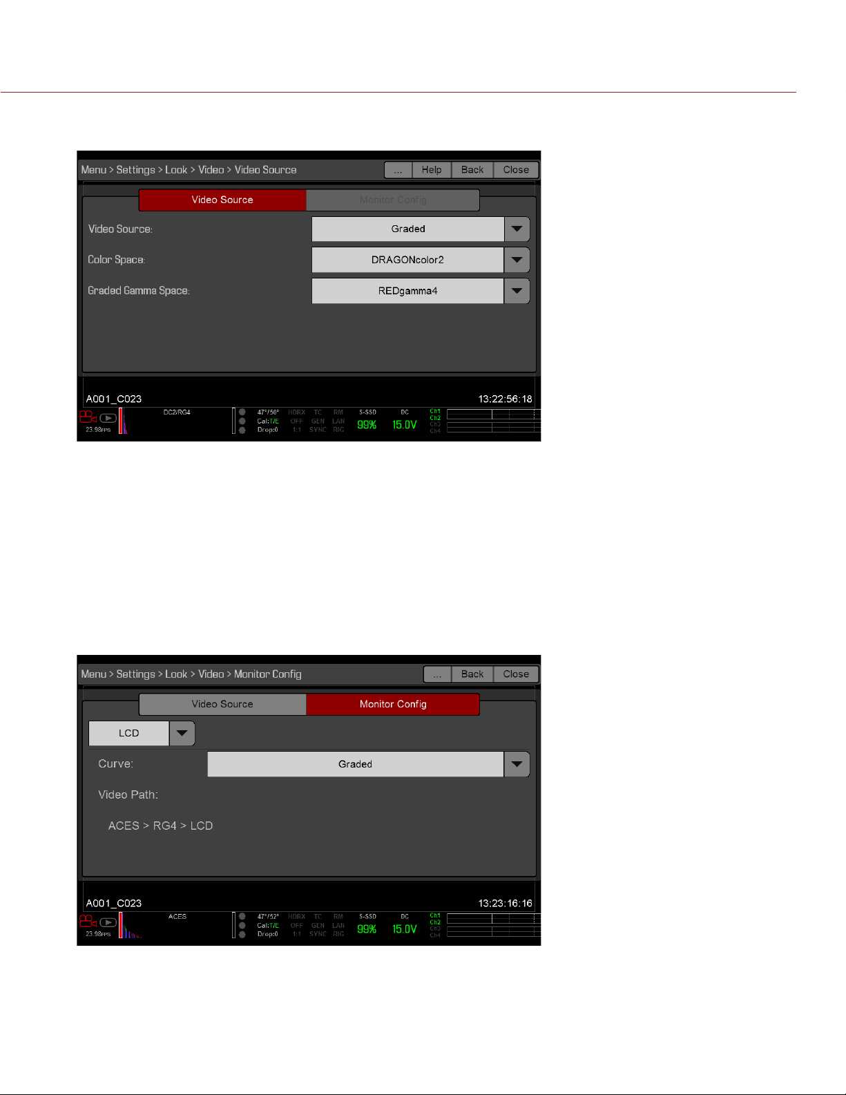
EPIC/SCARLET OPERATION GUIDE
4. IRLF and ACES: Set up the Monitor Configuration. For more information, go to “Monitor Config (Monitor
Configuration)” on page 80.
MONITOR CONFIG (MONITOR CONFIGURATION)
The Monitor Configu menu is available if the Video Source is set to RLF or ACES. For more information, go to
“Video Source” on page 74.
Use the Monitor Config menu to apply a curve to each monitor output.
1. Select the monitor to configure from the drop-down menu at the top of the menu.
2. Select a curve from the Curve drop-down menu:
‒ Neutral: The camera does not apply a graded gamma space to the monitor output.
‒ Graded: The camera applies a graded gamma space to the monitor output.
The Video Path displays the video source and graded gamma space applied to the monitor.
COPYRIGHT © 2016 RED.COM, INC
955-0020_V6.2, REV-J | 80
Page 81

EPIC/SCARLET OPERATION GUIDE
COLOR TEMPERATURE
Select a color temperature. The range is 1700 to 10,000 KELVIN, and the default is 5600 KELVIN.
NOTE: Color temperature is disabled on all Monochrome cameras.
NOTE: The Color Temperature settings are not accessible on cameras with Monochrome or RED DRAGON
Monochrome sensors.
TINT
Color temperature calculations assume a pure light source that may not be true in the specific scene the
camera is imaging. To compensate for any residual colorcast, the Tint parameter adjusts the RGB color balance
with a compensating magenta-green color component. Tint range is –100 to 100, with a default of 0.000.
NOTE: Selecting Auto White Balance calculates a new Tint value. The value does not change if you adjust the
color temperature manually. Selecting a preset resets Tint to 0.000.
NOTE: Tint is disabled on all Monochrome cameras.
PRESETS
Each preset has 0.000 Tint. Available preset options are:
Incandescent: 2800 K
Tungsten: 3200 K
Fluorescent: 4500 K
Flash: 5500 K
Daylight: 5600 K
Cloudy: 7500 K
Shade: 9000 K
AUTO WHITE BALANCE
Auto white balance analyzes the central 25% of the image visible in the monitor to calculate a color temperature
that will render a white object as white.
To use auto white balance, follow the instructions below:
1. Place a white or grey object under the ambient light.
2. Go to Menu > Settings > Look > Color Temp.
Alternatively, select Color Temperature > Advanced... from the Upper Status Row.
3. Select Auto White Balance.
LGG (LIFT, GAMMA, GAIN)
Adjust the lift, gamma, and gain for the Red channel, Blue channel, and Green channel individually.
PROJECT
The Project menu includes: Frame Rate, Exposure, Timecode, Slate, Format, and Sensor.
COPYRIGHT © 2016 RED.COM, INC 955-0020_V6.2, REV-J | 81
Page 82

EPIC/SCARLET OPERATION GUIDE
FRAME RATE
RECORDING FRAME RATE
Select the recording frame rate (also referred to as the capture frame rate). The recording frame rate is the
number of frames per second (fps) that are recorded. The recording frame rate is different from the project time
base, which is the rate at which the footage will be played back.
The default recording frame rate is 23.98 fps. If you change the project time base, the recording frame rate
automatically changes its value to match the project time base.
The maximum frame rate for each format is determined by several factors, including project time base,
REDCODE, and Lookaround. For more information about the maximum REDCODE settings for each common
recording frame rate, see the DSMC Media Operation Guide, available at www.red.com/downloads.
PROJECT TIME BASE
Select the project time base, which is the rate at which the footage will be played back. The project time base
displays in the lower left corner of the display.
The following project time bases are available:
23.98 fps (Default)
24.00 fps
25.00 fps
29.97 fps
47.95 fps
48.00 fps
50.00 fps
59.94 fps
VARISPEED
When a recording frame rate other than the current project time base is selected, the fps text turns yellow and
the word Varispeed replaces the Audio Meter in the lower right corner of the display.
Audio is not recorded in Varispeed mode.
EXPOSURE
Select the exposure (shutter speed) of each frame. You can change exposure while recording.
Decreasing shutter speed increases the amount of time that light hits the sensor, which increases exposure and
motion blur of moving objects. Increasing shutter speed decreases the amount of time that light hits the sensor,
which decreases exposure and motion blur of moving objects.
The Upper Status Row displays the exposure as either shutter speed or shutter angle. For more information,
go to “Exposure” on page 67.
If the camera is able to achieve the target exposure, the exposure value displays in white. If the camera is
unable to achieve the target exposure, the exposure value displays in yellow, and the camera uses the closest
available exposure.
NOTE: If using speed ramp mode, select an exposure that is valid for each ramp target frame rate. If the camera
ramps to a frame rate that is incompatible with the current exposure, the exposure changes to the longest
exposure possible for the frame rate. For more information, go to “Speed Ramp Mode” on page 93.
NOTE: You cannot change the exposure when HDR is enabled.
COPYRIGHT © 2016 RED.COM, INC
955-0020_V6.2, REV-J | 82
Page 83

EPIC/SCARLET OPERATION GUIDE
INTEGRATION TIME
Enter the exposure value as a shutter speed (1/xx sec).
MYSTERIUM-X: Slowest speed is 1/recording frame rate. For 24 fps, the slowest speed is 1/24 sec.
RED DRAGON: Slowest speed is 1/8 sec, regardless of the recording frame rate.
The fastest speed is 1/131,579 sec. Default is 1/48 sec.
SHUTTER ANGLE
Enter the exposure value as a shutter angle (xx°). Range is 1.000–360.000°. Default is 180.000°.
EXPOSURE CONVERSIONS
The table below lists common shutter speed and shutter angle equivalents.
SHUTTER SPEED (1/XX SEC) SHUTTER ANGLE (°) SHUTTER SPEED (1/XX SEC) SHUTTER ANGLE (°)
1/32 270 1/120 72
1/48 180 1/192 45
1/50 172.8 1/348 22.5
1/60 144 1/696 11
1/96 90 1/1000 8.6
CONVERT SHUTTER SPEED TO SHUTTER ANGLE
Shutter Angle = (Shutter Speed x Frame Rate x 360)
Example: (1/48 x 24 x 360) = 180
CONVERT SHUTTER ANGLE TO SHUTTER SPEED
Shutter Speed = 1/(Frame Rate x 360/Angle)
Example: 1/(24 x 360/180) = 1/48
TIMECODE
For more information about timecode, go to “Timecode, Genlock, Multi-Camera Setup” on page 135.
TIMECODE SOURCE MODE DESCRIPTION
User Provided (Internal) Use Real Time Clock
(RTC)
Set Manually Define a custom value as the timecode counter seed. Set
External: BRAIN Varies by device Uses the timecode from an external device connected to
Uses the internal Real Time Clock as the timecode counter
source. You can set the hours, minutes, and seconds in the
numerical boxes on the screen.
the hours, minutes, and seconds in the numerical boxes on
the screen.
the timecode connector on the camera.
External: Rear Module Varies by device Uses the timecode from an external device connected to a
Pro I/O Module or a REDCAST Module.
COPYRIGHT © 2016 RED.COM, INC 955-0020_V6.2, REV-J | 83
Page 84

EPIC/SCARLET OPERATION GUIDE
LTC OUT
The LTC Out (linear timecode out) check box is only available when a Pro I/O Module is attached. Select the
LTC Out check box to output the linear timecode signal generated by the camera through the timecode (TCODE)
port on the Pro I/O Module.
NOTE: If jamming camera timecode to a timecode device, ensure that LTC Out is disabled.
SLATE
Use the Slate menu to add metadata to clips. After configuring the following fields, the information populates
in the Media menu when formatting media:
Cam ID
Cam Pos
NOTE: The scene name is limited to eight (8) characters.
AUTO-INCREMENT TAKE
To automatically increment the take number when the camera stops recording, follow the instructions below:
1. Go to Menu > Settings > Project > Slate > Scene.
2. Enter a value in the Take box.
AUTO SLATE
Frame values for Auto Head Frames and Auto Tail Frames on the Auto Slate tab, these values only show in-camera.
The Auto Head Frames and Auto Tail Frames metadata values are currently disabled in REDCINE-X PRO.
FORMAT
Use the Format menu to select the resolution, aspect ratio, anamorphic setting, and lookaround setting. The
available aspect ratios are determined by the selected resolution.
After selecting format settings, select Set Format.
When you lower the resolution on a camera, only a portion of the sensor is used. The camera does not
downscale from full frame when recording RAW.
COPYRIGHT © 2016 RED.COM, INC
955-0020_V6.2, REV-J | 84
Page 85

EPIC/SCARLET OPERATION GUIDE
EPIC DRAGON FORMATS
The table below describes the formats that are available for EPIC DRAGON.
Default for EPIC DRAGON is 6K 2:1.
The table below omits rows for the anamorphic formats, since the pixel dimensions for each anamorphic format
and the corresponding non-anamorphic format are the same. For more information, go to “Anamorphic” on
page 89.
Using a 6:5 aspect ratio at 2x anamorphic gives you a 2.4:1 aspect ratio.
RESOLUTION DIMENSIONS (PIXELS) DIMENSIONS (MM)
WIDTH HEIGHT WIDTH HEIGHT DIAGONAL
6K FF 6144 3160 30.72 15.80 34.55
6K 2:1 6144 3072 30.72 15.36 34.35
6K 2.4:1 (WS) 6144 2592 30.72 12.96 33.34
6K 16:9 (HD) 5568 3132 27.84 15.66 31.94
6K 3:2 4752 3160 23.76 15.80 28.53
6K 6:5 3792 3160 18.96 15.80 24.68
6K 4:1 6144 1536 30.72 7.68 31.67
6K 8:1 6144 768 30.72 3.84 30.96
5.5K FF 5632 2948 28.16 14.74 31.78
5.5K 2:1 5632 2816 28.16 14.08 31.48
5.5K 2.4:1 (WS) 5632 2376 28.16 11.88 30.56
5.5K 16:9 (HD) 5376 3024 26.88 15.12 30.84
5.5K 4:1 5632 1408 28.16 7.04 29.03
5.5K 8:1 5632 704 28.16 3.52 28.38
5K FF 5120 2700 25.60 13.50 28.94
5K 2:1 5120 2560 25.60 12.80 28.62
5K 2.4:1 (WS) 5120 2160 25.60 10.80 27.78
5K 16:9 (HD) 4800 2700 24.00 13.50 27.54
5K 6:5 3240 2700 16.20 13.50 21.09
5K 4:1 5120 1280 25.60 6.40 26.39
5K 8:1 5120 640 25.60 3.20 25.80
4.5K FF 4608 2412 23.04 12.06 26.01
4.5K 2:1 4608 2304 23.04 11.52 25.76
4.5K 2.4:1 (WS) 4608 1944 23.04 9.72 25.01
4.5K 16:9 (HD) 4224 2376 21.12 11.88 24.23
4.5K 3:2 4320 2880 21.60 14.40 25.96
4.5K 4:1 4608 1152 23.04 5.76 23.75
4.5K 8:1 4608 576 23.04 2.88 23.22
4K FF 4096 2160 20.48 10.80 23.15
4K 2:1 4096 2048 20.48 10.24 22.90
COPYRIGHT © 2016 RED.COM, INC 955-0020_V6.2, REV-J | 85
Page 86

EPIC/SCARLET OPERATION GUIDE
RESOLUTION DIMENSIONS (PIXELS) DIMENSIONS (MM)
WIDTH HEIGHT WIDTH HEIGHT DIAGONAL
4K 2.4:1 (WS) 4096 1728 20.48 8.64 22.23
4K 16:9 (HD) 3840 2160 19.20 10.80 22.03
4K 6:5 2592 2160 12.96 10.80 16.87
4K 3:2 3840 2560 19.20 12.80 23.08
4K 4:3 3840 2880 19.20 14.40 24.00
4K 5:4 3840 3072 19.20 15.36 24.59
4K 4:1 4096 1024 20.48 5.12 21.11
4K 8:1 4096 512 20.48 2.56 20.64
3.5K FF 3584 1876 17.92 9.38 20.23
3.5K 2:1 3584 1792 17.92 8.96 20.04
3.5K 2.4:1 (WS) 3584 1512 17.92 7.56 19.45
3.5K 16:9 (HD) 3456 1944 17.28 9.72 19.83
3.5K 3:2 3360 2240 16.80 11.20 20.19
3.5K 4:3 3360 2520 16.80 12.60 21.00
3.5K 5:4 3360 2688 16.80 13.44 21.51
3.5K 4:1 3584 896 17.92 4.48 18.47
3.5K 8:1 3584 448 17.92 2.24 18.06
3K FF 3072 1620 15.36 8.10 17.36
3K 2:1 3072 1536 15.36 7.68 17.17
3K 2.4:1 (WS) 3072 1296 15.36 6.48 16.67
3K 16:9 (HD) 2880 1620 14.40 8.10 16.52
3K 6:5 1944 1620 9.72 8.10 12.65
3K 3:2 2880 1920 14.40 9.60 17.31
3K 4:3 2880 2160 14.40 10.80 18.00
3K 5:4 2880 2304 14.40 11.52 18.44
3K 4:1 3072 768 15.36 3.84 15.83
3K 8:1 3072 384 15.36 1.92 15.48
2.5K FF 2560 1340 12.80 6.70 14.45
2.5K 2:1 2560 1280 12.80 6.40 14.31
2.5K 2.4:1 (WS) 2560 1080 12.80 5.40 13.89
2.5K 16:9 (HD) 2304 1296 11.52 6.48 13.22
2.5K 3:2 2400 1600 12.00 8.00 14.42
2.5K 4:3 2400 1800 12.00 9.00 15.00
2.5K 5:4 2400 1920 12.00 9.60 15.37
2.5K 4:1 2560 640 12.80 3.20 13.19
2.5K 8:1 2560 320 12.80 1.60 12.90
COPYRIGHT © 2016 RED.COM, INC
955-0020_V6.2, REV-J | 86
Page 87

EPIC/SCARLET OPERATION GUIDE
RESOLUTION DIMENSIONS (PIXELS) DIMENSIONS (MM)
WIDTH HEIGHT WIDTH HEIGHT DIAGONAL
2K FF 2048 1080 10.24 5.40 11.58
2K 2:1 2048 1024 10.24 5.12 11.45
2K 2.4:1 (WS) 2048 864 10.24 4.32 11.11
2K 16:9 (HD) 1920 1080 9.60 5.40 11.01
2K 3:2 1920 1280 9.60 6.40 11.54
2K 4:3 1920 1440 9.60 7.20 12.00
2K 5:4 1920 1536 9.60 7.68 12.29
2K 6:5 1296 1080 6.48 5.40 8.44
2K 4:1 2048 512 10.24 2.56 10.56
2K 8:1 2048 256 10.24 1.28 10.32
SCARLET DRAGON FORMATS
The table below describes the formats that are available for SCARLET DRAGON.
SCARLET DRAGON offers a 6:5 aspect ratio for each resolution. Using a 6:5 aspect ratio at 2x anamorphic
gives you a 2:40:1 aspect ratio.
RESOLUTION DIMENSIONS (PIXELS) DIMENSIONS (MM)
WIDTH HEIGHT WIDTH HEIGHT DIAGONAL
6K 6144 3160 30.72 15.80 34.55
6K 3:2 4752 3160 23.76 15.80 28.53
6K 6:5 3792 3160 18.96 15.80 24.68
5K 5120 2700 25.60 13.50 28.94
5K 2:1 5120 2560 25.60 12.80 28.62
5K 2.4:1 (WS) 5120 2160 25.60 10.80 27.78
5K 16:9 (HD) 4800 2700 24.00 13.50 27.54
5K 6:5 3240 2700 16.20 13.50 21.09
4K 4096 2160 20.48 10.80 23.15
4K 2:1 4096 2048 20.48 10.24 22.90
4K 2.4:1 (WS) 4096 1728 20.48 8.64 22.23
4K 16:9 (HD) 3840 2160 19.20 10.80 22.03
4K 6:5 2592 2160 12.96 10.80 16.87
3K 3072 1620 15.36 8.10 17.36
3K 2:1 3072 1536 15.36 7.68 17.17
3K 2.4:1 (WS) 3072 1296 15.36 6.48 16.67
3K 16:9 (HD) 2880 1620 14.40 8.10 16.52
3K 6:5 1944 1620 9.72 8.10 12.65
2K 2048 1080 10.24 5.40 11.58
COPYRIGHT © 2016 RED.COM, INC 955-0020_V6.2, REV-J | 87
Page 88

EPIC/SCARLET OPERATION GUIDE
RESOLUTION DIMENSIONS (PIXELS) DIMENSIONS (MM)
WIDTH HEIGHT WIDTH HEIGHT DIAGONAL
2K 2:1 2048 1024 10.24 5.12 11.45
2K 2.4:1 (WS) 2048 864 10.24 4.32 11.11
2K 16:9 (HD) 1920 1080 9.60 5.40 11.01
2K 6:5 1296 1080 6.48 5.40 8.44
EPIC MYSTERIUM-X AND SCARLET MYSTERIUM-X FORMATS
The table below describes the formats that are available for EPIC MYSTERIUM-X and SCARLET MYSTERIUM-X.
EPIC MYSTERIUM-X: Default is 5K 2:1.
SCARLET MYSTERIUM-X: Default is 4K.
The table below omits rows for the anamorphic formats, since the pixel dimensions for each anamorphic format
and the corresponding non-anamorphic format are the same. For more information, go to “Anamorphic” on
page 89.
RESOLUTION DIMENSIONS (PIXELS) DIMENSIONS (MM)
WIDTH HEIGHT WIDTH HEIGHT DIAGONAL
5K FF 5120 2700 27.65 14.58 31.26
5K 2:1 5120 2560 27.65 13.82 30.91
5K 2.4:1 (WS) 5120 2160 27.65 11.66 30.01
5K 16:9 (HD) 4800 2700 25.92 14.58 29.74
5K 1.22:1 3300 2700 17.80 14.58 23.01
4K FF 4096 2160 22.12 11.66 25.01
4K 2.4:1 (WS) 4096 1708 22.12 9.22 23.96
4K 16:9 (HD) 3840 2160 20.74 11.66 23.79
3K FF 3072 1620 16.59 8.75 18.75
3K 2.4:1 (WS) 3072 1284 16.59 6.93 17.98
3K 16:9 (HD) 2880 1620 15.55 8.75 17.84
2K FF 2048 1080 11.06 5.83 12.50
2K 2.4:1 (WS) 2048 854 11.06 4.61 11.98
2K 16:9 (HD) 1920 1080 10.37 5.83 11.90
1K 16:9 (HD) 1280 720 6.91 3.89 7.93
1K 2.4:1 (WS) 1280 480 6.91 2.59 7.38
COPYRIGHT © 2016 RED.COM, INC
955-0020_V6.2, REV-J | 88
Page 89
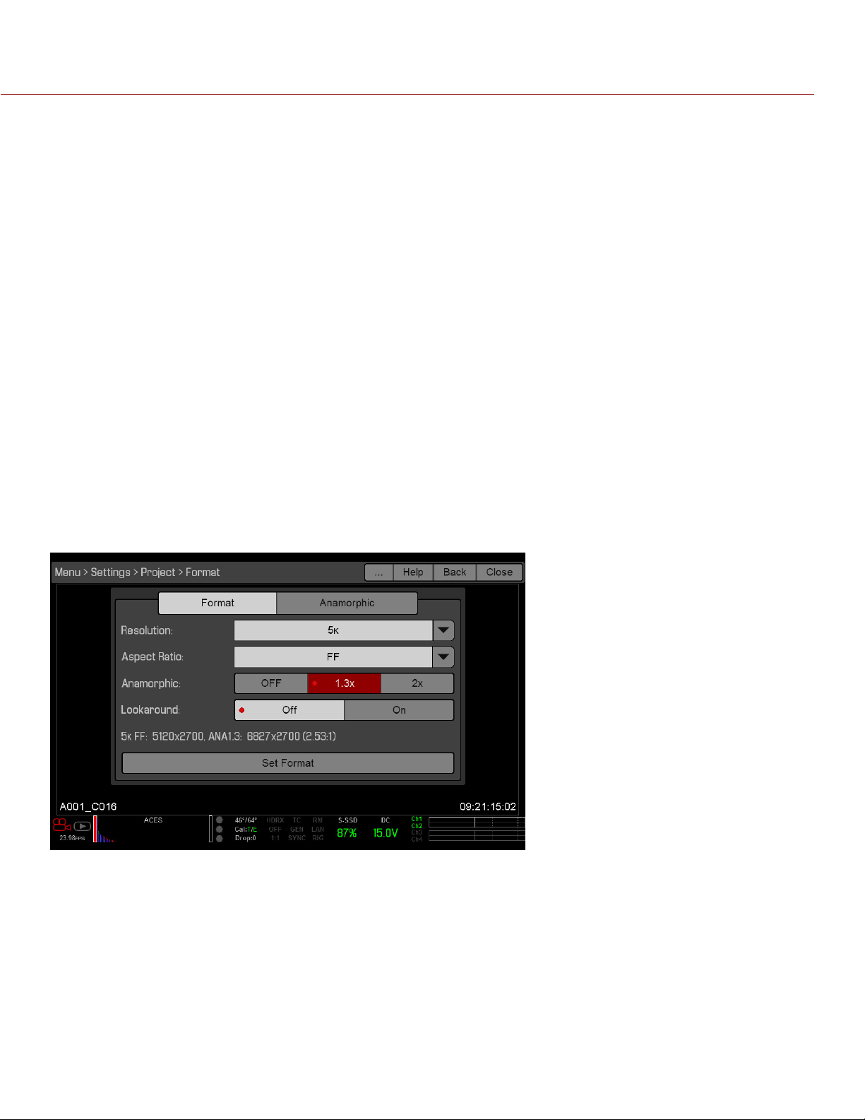
EPIC/SCARLET OPERATION GUIDE
ANAMORPHIC
Select an Anamorphic setting, if applicable. The anamorphic setting de-squeezes the image on the monitor
and marks the footage as anamorphic in the clip metadata. When you open the clip in REDCINE-X PRO, the
program automatically de-squeezes the image. The available anamorphic settings depend on your camera type.
EPIC DRAGON: Supports anamorphic 1.3x and 2x with each format.
SCARLET DRAGON: Supports anamorphic 2x for 5K 6:5.
EPIC MYSTERIUM-X and SCARLET MYSTERIUM-X: Supports the following:
‒ 5K FF: Anamorphic 1.3x and 2x
‒ 5K 1.22:1: Anamorphic 2x
NOTE: Anamorphic de-squeeze on the RED PRO LCD 7.0" requires that your camera is on firmware v5.3 or later.
DE-SQUEEZED RESOLUTION AND DE-SQUEEZED ASPECT RATIO
When you enable anamorphic, both the actual format and the de-squeezed format display at the bottom of the
Format menu. To view the actual format and the de-squeezed format, go to Menu > Settings > Project > Format
> Format.
When anamorphic is enabled, the camera does not crop the sensor image, so the recorded image has the same
resolution and dimensions as the corresponding non-anamorphic format.
After de-squeezing the footage in post production, the resulting footage has a different format than the original
recorded image. The format of the de-squeezed footage is the second format (resolution and aspect ratio) that
displays on the Format menu.
Since the camera does not crop the image, you will have additional horizontal area to frame the image. Then,
crop or scale the footage to the intended aspect ratio.
COPYRIGHT © 2016 RED.COM, INC 955-0020_V6.2, REV-J | 89
Page 90
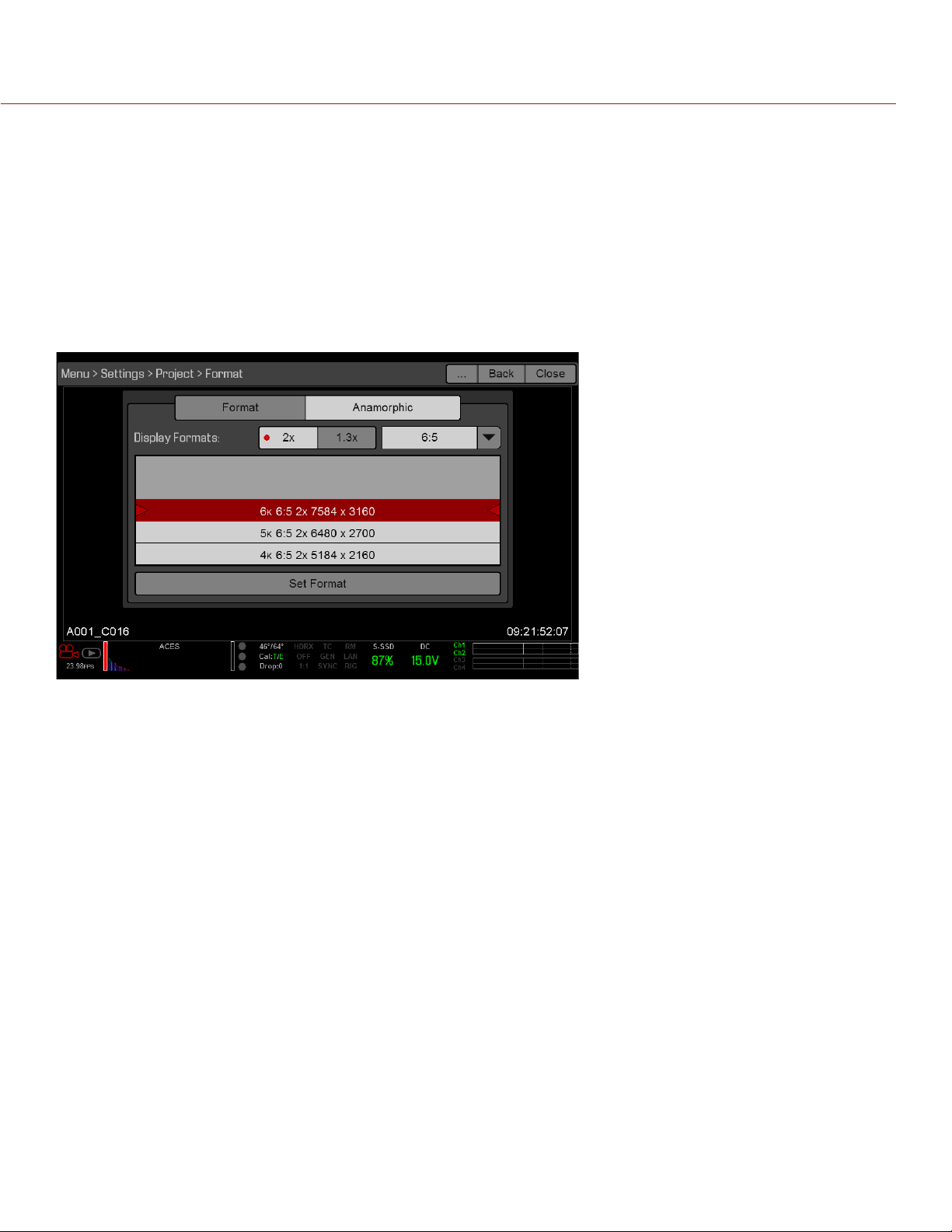
EPIC/SCARLET OPERATION GUIDE
SHORT-CUT TO INDUSTRY-STANDARD ANAMORPHIC FORMATS
To quickly access industry-standard anamorphic formats, go to Menu > Settings > Project > Format > Anamorphic.
The Anamorphic tab is a short-cut to all of the industry-standard anamorphic formats, so that you can easily
select the most common anamorphic formats.
The Anamorphic tab lists the following anamorphic formats:
EPIC DRAGON: Every format with a 6:5, 5:4, or 4:3 aspect ratio and a 1.3x or 2x anamorphic setting
SCARLET DRAGON: 5K 6:5 2x
EPIC MYSTERIUM-X and SCARLET MYSTERIUM-X: 5K 1.22:1 2x
NOTE: The Anamorphic tab only lists industry-standard anamorphic formats. To access all of the anamorphic
and non-anamorphic formats, go to Menu > Settings > Project > Format > Format.
LOOKAROUND
When Lookaround is enabled, the Frame Guide and recording area are scaled down on the display so that you
can see what images will enter the recording area.
To assign a Shading overlay to the Lookaround area (the area outside of the recording area), go to “General
Tab” on page 77.
Lookaround limits the available frame rates. Also, Lookaround is either very limited or not possible for high
resolutions (such as 5K Full Frame in EPIC MYSTERIUM-X and 6K Full Frame in EPIC DRAGON). At high
resolutions, the recording area on the display shows the full sensor area or full sensor height, so there is no
extra room for Lookaround.
UHD
The UHD menu is only accessible when a REDCAST Module is installed. For more information, see the REDCAST
MODULE Operation Guide, available at www.red.com/downloads.
COPYRIGHT © 2016 RED.COM, INC
955-0020_V6.2, REV-J | 90
Page 91
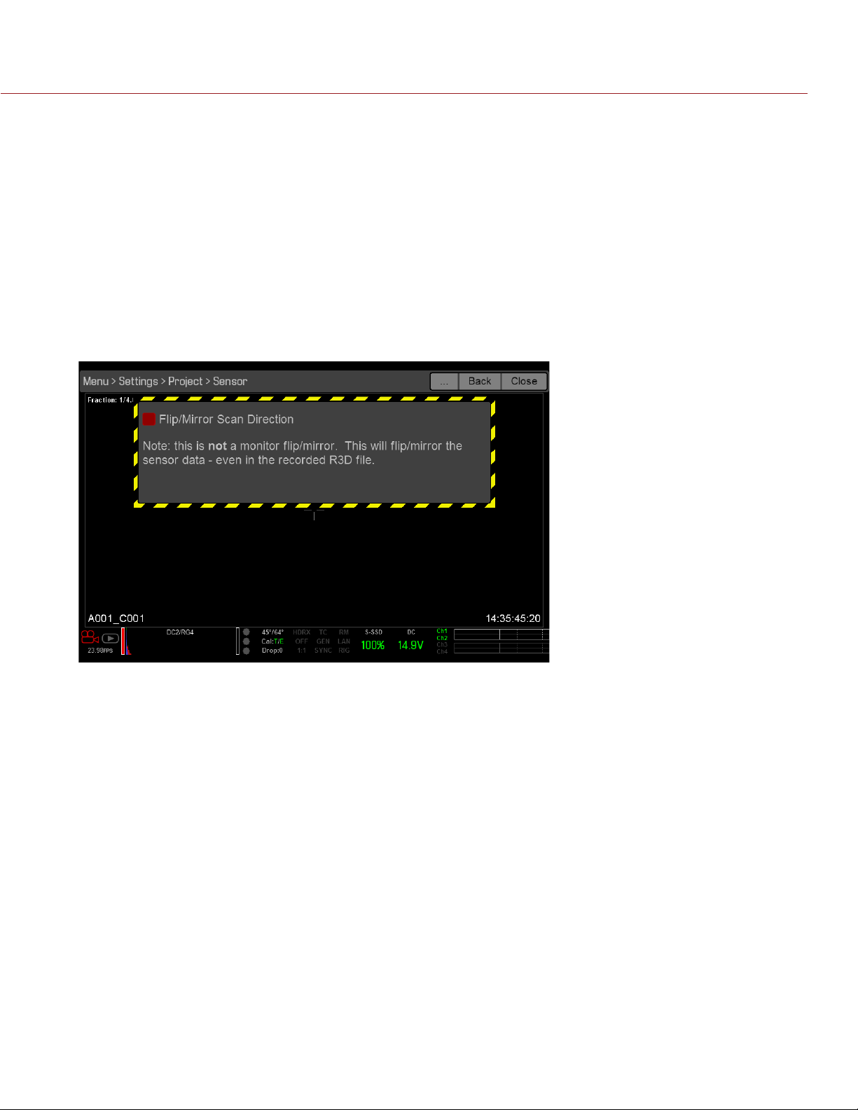
EPIC/SCARLET OPERATION GUIDE
SENSOR (FLIP/MIRROR SCAN DIRECTION)
NOTE: Flip/Mirror Scan Direction is only available on an EPIC DRAGON or SCARLET DRAGON.
The Flip/Mirror Scan Direction feature rotates the image 180°, both on the monitor and in the recorded R3D file.
Normally, the sensor scans the image from the top to the bottom. When the Flip/Mirror Scan Direction feature
is enabled, the sensor scan direction reverses, and the sensor scans the image from the bottom to the top.
The Flip/Mirror Scan Direction feature is intended for multi-camera arrays when all sensors are synchronized,
and at least one (1) camera is mounted upside-down. Using this feature is helpful for matching the line scan
direction for the cameras in the array.
To enable the Flip/Mirror Scan Direction feature, follow the instructions below:
1. Go to Menu > Settings > Project > Sensor.
2. Select the Flip/Mirror Scan Direction check box.
The camera rotates the image 180° on the monitor and in the recorded R3D file.
AUDIO
The Audio menu lets you configure the audio subsystem. For more information, go to “Record and Monitor
Audio” on page 130.
RECORDING
The Recording menu includes: Mode, Codec, Frame Processing, Pre-Record, and Indicator.
MODE
You can select the following recording modes: Continuous Record, Internal Timelapse Timer, Frame Trigger,
REDCODE Burst, Speed Ramp Mode, Multi-Shot, and Motion + Stills.
NOTE: Audio is recorded only in Continuous Record and Motion + Stills modes.
COPYRIGHT © 2016 RED.COM, INC 955-0020_V6.2, REV-J | 91
Page 92

EPIC/SCARLET OPERATION GUIDE
STORAGE
You can select the following storage locations:
Local: Stores footage directly to an SSD
Network: Stores footage to a network
NOTE: HDRx is disabled in Network Storage mode.
NOTE: The Network option is only available on an EPIC DRAGON or SCARLET DRAGON.
External: Stores footage to an external device
NOTE: In External storage, you can only select Continuous Record and Motion + Stills recording modes.
CONTINUOUS RECORD
NOTE: This mode is not available in Stills mode.
Continuous Record is the “normal” recording mode. The camera continuously records frames at the current
recording frame rate. You can limit each recording to a specific amount of frames using the Limit Recording to
setting.
INTERNAL TIMELAPSE TIMER
NOTE: This mode is not available in Stills mode.
NOTE: Audio is not recorded in Internal Timelapse Timer mode.
In Internal Timelapse Timer mode, the camera records a specified number of frames at a specified interval. The
current recording frame rate determines the timing of the frames per pulse.
For example, in Internal Timelapse Timer mode, you can choose to record a total amount of 1000 frames, and
take 1 frame every 4.67 seconds. After recording 1000 frames (which takes 4,670.00 seconds), the recording
process stops.
To use Internal Timelapse Timer mode, follow the instructions below:
1. Go to Menu > Settings > Recording > Mode.
2. Select Internal Timelapse Timer from the Mode drop-down menu.
3. Use the Limit Recording to fields to set the recording to end at a predefined frame limit (optional).
4. Select the number of frames to be captured in the Record field.
5. Select the time interval from the Interval field (range is 1–3,599 sec). The Interval setting specifies the
frequency at which the frame or group of frames is captured.
6. Close the menu.
7. Start recording to start the interval.
The overlay displays the number of frames recorded out of the total amount of frames.
COPYRIGHT © 2016 RED.COM, INC
955-0020_V6.2, REV-J | 92
Page 93

EPIC/SCARLET OPERATION GUIDE
FRAME TRIGGER
NOTE: This mode is not available in Stills mode.
NOTE: Audio is not recorded in Frame Trigger mode.
In Frame Trigger mode, the camera records the specified number of frames for each external trigger. This mode
limits the REDCODE based on sustainable record rates.
To use Frame Trigger mode, follow the instructions below:
1. Go to Menu > Settings > Recording > Mode.
2. Select Frame Trigger from the Mode drop-down menu.
3. Use the Limit Recording to fields to set the recording to end at a predefined frame limit (optional).
4. Select a Pre Count and Post Count. For more information, go to “Pre Count and Post Count” on page 94.
5. Close the menu.
6. Start recording.
The overlay displays the number of frames recorded out of the total amount of frames.
NOTE: There may be a delay between receiving the external trigger and capturing the next frame(s). The delay
may be as long one (1) frame period at the current recording frame rate. To completely synchronize frames to
an external trigger, set Sensor Sync Mode to MoCo. For more information, go to “Sync” on page 101.
SPEED RAMP MODE
NOTE: This mode is not available in Stills mode.
NOTE: Audio is not recorded in Speed Ramp mode.
Speed Ramp mode lets you program the current recording frame rate to transition to different recording frame
rates during recording.
1. Go to Menu > Settings > Recording > Mode.
2. Select Speed Ramp Mode from the Mode drop-down menu.
3. Use the Limit Recording to fields to set the recording to end at a predefined frame limit (optional).
4. Select a ramp target:
‒ Ramp A/B/C/D: Each ramp target is tied to a specific Target/Duration combination.
‒ Ramp Reset: Ramp to the starting frame rate with the specified Duration.
5. Set the Target frame rate.
6. Set the Duration, which is how long it takes to transition from the current frame rate to the target frame rate.
7. Go to Menu > Settings > Setup > Keys and program a key to one of the following functions:
‒ Record: Start Speed Ramp A/B/C/D
‒ Record: Start Speed Ramp Reset
8. Start recording.
9. To start speed ramp, press the key that you have mapped to start the speed ramp.
The frame rate transitions to the target frame rate during the duration you set up.
NOTE: If using speed ramp mode, select an exposure that is valid for each ramp target frame rate. If the camera
ramps to a frame rate that is incompatible with the current exposure, the exposure changes to the longest
exposure possible for the frame rate.
COPYRIGHT © 2016 RED.COM, INC 955-0020_V6.2, REV-J | 93
Page 94
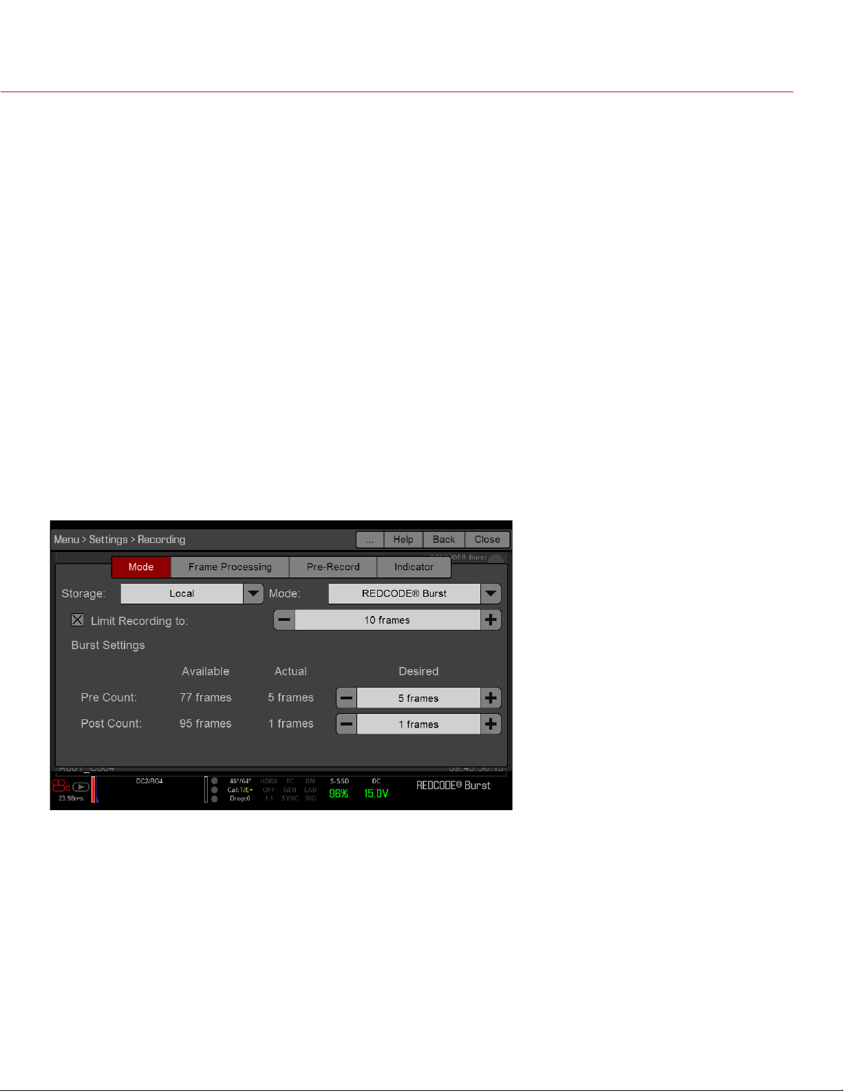
EPIC/SCARLET OPERATION GUIDE
REDCODE BURST
NOTE: This mode is not available in Stills mode.
NOTE: Audio is not recorded in REDCODE Burst mode.
In REDCODE Burst mode, the camera can record at a lower compression (REDCODE) for the specified amount
of frames. When REDCODE Burst mode is enabled and recording starts, the camera captures a “burst” of
frames at the lower REDCODE, and then continues to record at the next available REDCODE. To add more
bursts to clips during recording, press any key mapped to “Record: Mark Frame”.
To use REDCODE Burst mode, follow the instructions below:
1. Go to Menu > Settings > Recording > Mode.
2. Select REDCODE Burst from the Mode drop-down menu.
3. Use the Limit Recording to fields to set the recording to end at a predefined frame limit (optional).
4. Select a Pre Count and Post Count. For more information, go to “Pre Count and Post Count” on page 94
5. Close the menu.
6. Start recording.
PRE COUNT AND POST COUNT
When Frame Trigger or Burst mode is enabled, select the number of frames for the Pre Count and Post Count:
Pre Count: The camera captures the frame cache from the time preceding the marker.
Post Count: The camera captures the remaining frame cache after the marker.
The maximum frame counts are listed in the Available column, and are based on format and REDCODE.
COPYRIGHT © 2016 RED.COM, INC
955-0020_V6.2, REV-J | 94
Page 95

EPIC/SCARLET OPERATION GUIDE
MULTI-SHOT
NOTE: Multi-Shot mode is only available on an EPIC DRAGON or SCARLET DRAGON.
NOTE: The camera does not sync timecode in Multi-Shot mode.
NOTE: This mode is available in Motion mode, but is only recommended in Stills mode.
NOTE: Audio is not recorded in Multi-Shot mode.
Multi-Shot mode removes restrictions on Recording Frame Rate and REDCODE, allowing you to shoot at a high
resolution, high frame rate, and low compression. These restrictions are removed because the camera records
first to the camera’s memory, and then offloads (while recording) to SSD after the camera’s buffer fills up. Since
the camera records only as fast as the buffer can transfer data, frames are dropped from the clip.
Multi-Shot mode has two sub-modes:
Basic Multi-Shot mode
Advanced Multi-Shot mode
BASIC MULTI-SHOT MODE
In Basic Multi-Shot mode, you can record a one-frame clip by pressing a Record key, or you can continuously
record frames by holding a Record key. This mode is the easiest way to shoot stills, but there is some latency
(about 700 milliseconds) when you press Record.
This mode only involves Record keys on the side SSD modules, REDMOTE, and DSMC Side Handle. Pressing
the PWR/REC key on the camera initiates Advanced Multi-Shot mode.
To use Basic Multi-Shot mode, perform one of the following:
Press a Record key to record a one-frame clip.
Press and hold a Record key to start a new clip and continuously add frames to that clip. Release the Record
key to stop adding frames and end the clip.
ADVANCED MULTI-SHOT MODE
In this mode, the camera is continuously recording, but is not saving frames. This eliminates the delay you get
in Basic Multi-Shot mode. Since the camera is continuously recording, the camera requires the same amount
of power it does during Continuous Record (as opposed to Preview mode). Unlike Basic mode, all frames are
added to one (1) clip, instead of to separate clips.
To use Advanced Multi-Shot mode, follow the instructions below:
1. Press the PWR/REC key on the camera to start a new clip. This initial press adds one (1) frame to the clip.
2. Press a Record key on the side SSD module, REDMOTE, or DSMC Side Handle to add frames to the clip:
‒ Press a Record key once to add a few frames to the clip. (The number of frames varies, and depends
on the buffer.)
‒ Press and hold a Record key to continuously add frames; release the Record key to stop adding frames.
3. Press the PWR/REC key on the camera to end the clip.
NOTE: You cannot shut down the camera until you end the clip.
COPYRIGHT © 2016 RED.COM, INC 955-0020_V6.2, REV-J | 95
Page 96

EPIC/SCARLET OPERATION GUIDE
ENABLE MULTI-SHOT MODE
To enable Multi-Shot mode, follow the instructions below:
1. Set the camera to Stills mode.
2. Go to Menu > Settings > Recording > Mode.
3. Select Multi-Shot from the Mode drop-down menu.
4. Use the Limit Recording to fields to set the recording to end at a predefined frame limit (optional).
5. Close the menu.
6. For more information on using the different sub-modes, go to:
‒ “Basic Multi-Shot Mode” on page 95
‒ “Advanced Multi-Shot Mode” on page 95
MOTION + STILLS
NOTE: This mode is available in Motion mode, but is only recommended in Stills mode.
Motion + Stills mode is identical to Continuous Record, except that when you initiate recording by pressing
the PWR/REC key on the camera, all other Record keys mark frames for the duration of the clip. (If you initiate
recording by pressing any other Record key, you can press any key mapped to “Record: Mark Frame” to mark
stills.)
To use Motion + Stills mode, follow the instructions below:
1. Set the camera to Stills mode.
2. Go to Menu > Settings > Recording > Mode.
3. Select Motion + Stills from the Mode drop-down menu.
4. Use the Limit Recording to fields to set the recording to end at a predefined frame limit (optional).
5. Close the menu.
6. Press the PWR/REC key on the camera to start recording.
7. Press a Record key on the side SSD module, REDMOTE, or DSMC Side Handle to mark a frame.
8. Press the PWR/REC key on the camera to stop recording.
CODEC
Select the target REDCODE compression ratio for your project from the REDCODE drop-down menu. For more
information, go to “REDCODE” on page 41.
FRAME PROCESSING
NOTE: Frame processing is not supported in Speed Ramp Mode. For more information, go to “Speed Ramp
Mode” on page 93.
Frame processing allows for the combination of multiple captured frames into one recorded frame. The
combination occurs before the resulting frame is encoded. You can select the following frame processing
settings: No Frame Processing, Frame Summing, Frame Averaging.
When in Frame Summing mode or Frame Averaging mode, the current integration time is applied to each frame.
This means if the integration time is not the entire frame time (or 360°) there are gaps between the images used
to create the combined frame. This may lead to unexpected motion artifacts.
The effect of frame processing is only visible during record. In Frame Summing mode, this means the exposure
changes between preview and record. Experiment with the exposure and frame processing settings to achieve
the effect you want.
NO FRAME PROCESSING
Normal frame processing mode. The Frames to Process selection does not affect recording.
COPYRIGHT © 2016 RED.COM, INC
955-0020_V6.2, REV-J | 96
Page 97

EPIC/SCARLET OPERATION GUIDE
FRAME SUMMING
Frame Summing combines the specified number of frames into one frame, and adds together the exposure time
for each of the original frames. The resulting frame has an effective integration time that is equal to the current
integration time multiplied by the number of frames.
For example, if you select 16 as the Frames to Process value, and set exposure to 1/48 sec, the resulting image
has an effective integration time of 1/3 sec (16 x 1/48).
Frame summing results in a final image that is brighter and possibly blurrier than any of the original frames, so
you can use frame summing to achieve the effect of long-exposure.
FRAME AVERAGING
Frame Averaging combines the specified number of frames into one frame, and averages the exposure time
for each of the original frames. The resulting frame has an effective integration time that is equal to the current
integration time.
For example, if you select 16 as the Frames to Process value, and set exposure to 1/48 sec, the resulting image
still has the exposure value of 1/48 sec, along with the effect of long-exposure.
You can use frame averaging to achieve the effect of long-exposure along with the benefits of reduced noise.
However, frame averaging does affect motion blur characteristics.
PRE-RECORD
When enabled, the Pre-Record setting continuously captures a cache of footage before recording starts. Select
to have 4–30 seconds (incremented at two second intervals) of pre-record time added to the actual footage.
When Pre-Record is enabled, you will not miss the start of a shot by being a little slow on the trigger.
Pre-Record Duration: Select the pre-record time.
Always trigger Pre-Record before recording: When selected, Pre-Record always starts when recording starts:
A. Press PWR/REC to activate Pre-Record.
B. Press PWR/REC a second time to start recording.
C. Press PWR/REC a third time to stop recording.
Trigger Pre-Record Now: When selected, the Pre-Record menu closes and Pre-Record mode starts.
NOTE: Always perform a Secure Format before using Pre-Record. A Secure Format restores the SSD back to
factory out-of-box settings, and optimizes the SSD for Pre-Record.
NOTE: To use Pre-Record only for specific situations, map Pre-Record to a key (Menu > Settings > Setup > Keys
> Record: Start Pre-Record). For more information, go to “Keys” on page 98.
INDICATOR
Enable Sounds: Select this check box to enable sounds. Then select sounds for the following actions:
‒ Record Start
‒ Record Stop
‒ Mark Still Frame
EVF Tally Light: Select this check box to enable the EVF Record Tally LED on the EVF to illuminate red when
recording.
SETUP
The Setup menu includes: Keys, Date/Time, Communication, REDMOTE, GPIO/Sync, Fan Control, Lens, and
Motor Control.
COPYRIGHT © 2016 RED.COM, INC 955-0020_V6.2, REV-J | 97
Page 98

EPIC/SCARLET OPERATION GUIDE
KEYS
Map keys to often-used actions to easily control the camera. For a full list of the default key mappings, go to
“Default Key Functions” on page 188.
KEY MAPPING
To map or remap a user key:
1. Press the user key that you want to map.
2. Select an action from the Press (or CCW) drop-down menu that you want to map to the user key.
3. To un-map a key, select -Key Disabled- from the drop-down menu.
4. If you want, map a Release or (CW) action to the key.
A Release action occurs when a pressed key is released.
OPTIONS
Lock Side Module keys: None of the module keys perform any actions when pressed, unless you set up the
exceptions below:
‒ Record key remains active when locked
‒ Navigation keys remain active when locked
Show key action notifications: A notification displays on the bottom of the display when you perform an
action mapped to a key.
SOFT KEYS
The following sets of soft keys are available on the touchscreen:
A, B, C, D: Left side of the touchscreen
1, 2, 3, 4: Right side of the touchscreen
To map or remap a soft key, select an action from the drop-down menu next to the key you want to map.
Enable Soft Keys on touchscreen: Tap the left or right side of the touchscreen to show the soft keys.
Show key actions as labels: When the soft keys display, the number/letter of the key and the key action
display.
ADVANCED
Use the Advanced tab to map any key, even if the key is not currently accessible. For example, you can map
the REDMOTE keys even if a REDMOTE is not present.
WARNING: It is possible to remap the navigation keys using this tab. However, if you do not have a touchscreen
attached, it is possible to lock out control. Be careful when remapping navigation keys.
DATE/TIME
Use the Date/Time menu to reset the internal clock of the camera. The time and date are timestamps on R3D
files when recording to an SSD. The camera uses the 24-hour clock convention (military time). For example,
enter 2:35 p.m. as 14:35:00.
The date and time are saved when you close the Date/Time menu.
COPYRIGHT © 2016 RED.COM, INC
955-0020_V6.2, REV-J | 98
Page 99
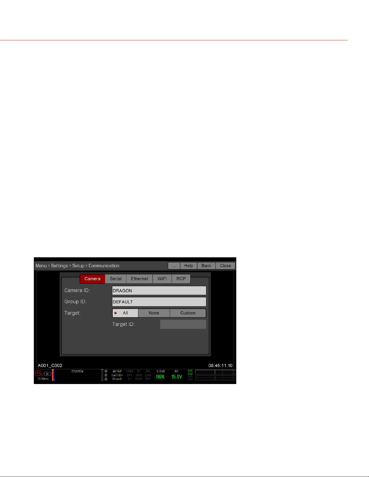
EPIC/SCARLET OPERATION GUIDE
COMMUNICATION
Use the Communication menu to allow one (1) or more cameras to communicate with each other or external
devices.
You can use the serial port or a direct Ethernet cable to connect two (2) cameras, or one (1) camera and one
(1) external device. If the camera is connected via Ethernet to a hub or router, multiple cameras and devices
can communicate with each other.
For example, on a multi-rig 3D shoot, you can send commands to an individual camera (Example: Set CAM_A_L
to 1/48 exposure), to a group of cameras (Example: Set 3DRIG_A to 48 fps), or to all cameras (Example: Start
Recording on all cameras).
CAMERA NAME
Use the Camera menu to set up a unique identifier for your camera (or a group of cameras). All command
filtering happens on the receiver side of the communication link. Use camera names and group names to
address commands to a specific camera or group of networked cameras.
Camera ID: Enter a unique camera name to use in network communications. The field is limited to eight (8)
characters.
Group ID: Enter a group name to identify the camera as a member of a group of devices. The field is limited
to eight (8) characters, and the default name is DEFAULT.
Target: Specify which devices the camera can send commands to:
‒ All: The camera can send commands to all devices on the network.
‒ None: The camera can only receive commands. The camera cannot send commands.
‒ Custom: The camera can send commands to a specific camera/device (enter the name of the camera/
device in the Target ID text box) or a specific group (enter the name of the group in the Target ID text
box). The camera/group name must match the name entered in the Name/Group field of the target
device(s).
COPYRIGHT © 2016 RED.COM, INC 955-0020_V6.2, REV-J | 99
Page 100

EPIC/SCARLET OPERATION GUIDE
SERIAL PROTOCOL
The camera can communicate to external devices via the CTRL and the GIG-E connectors (camera-to-camera
communication is possible only via GIG-E or the REDLINK® Bridge).
Select one of the following protocols from the Serial Protocol drop-down menu:
None (Default)
Element Technica
3ality SPC 7XXX
REDLINK Command Protocol
ETHERNET
Use the settings on the Ethernet tab to configure the GIG-E port. Each camera or device requires a unique IP
address. For camera-to-camera communication via Ethernet, both cameras need to be in the same sub-net
(have the same netmask address) and have the same gateway address.
Enable DHCP: Enables DHCP. If a DHCP-server is available in the communications network, the camera
obtains an IP address, netmask address, and gateway address automatically from the DHCP server. You
cannot manually enter anything in the IP Address, Netmask, and Gateway fields when this check box is
selected.
Enable Camera to Camera: A change to settings on this camera is sent to other cameras via the network as
a SET command (as UDP packets). The SET command then sets the property on other cameras. If this
camera receives a SET command, the camera does not send the command to other cameras/devices.
Enable External Control: This camera can be controlled via TCP/IP from an external device.
WIFI
The settings on the WiFi menu are only used when a REDLINK Bridge is attached to the camera. For more
information, see the REDLINK Bridge Operation Guide, available at www.red.com/downloads.
RCP
Select the Enable Remote Control Panel (RCP) check box to enable a remote control panel (RCP).
COMPATIBLE REMOTE CONTROL PANELS (RCP)
The following remote control panels have been confirmed for compatibility with the camera:
Sony® RCP-1500
Sony RCP-1501
Sony RCP-1530
Sony MSU-1500
REDMOTE
Use the REDMOTE menu to pair a REDMOTE to the camera. For more information, go to “REDMOTE Operation”
on page 146.
Wireless Enable: When selected, the camera produces a wireless signal. Disable wireless in any setting in
which the wireless signal could interfere with other devices, such as in a helicopter.
Wireless Channel: Select the communication channel for the wireless connection in the event of interference
from other wireless devices.
Camera MAC: View the camera MAC address.
COPYRIGHT © 2016 RED.COM, INC
955-0020_V6.2, REV-J | 100
 Loading...