

RED PERFORMA 25, PERFORMA 30, PERFORMA 25 EasyClean, PERFORMA 30 EasyClean Installation Manual
Page 1
INSTALLATION GUIDE EN
PELLET BOILER
PERFORMA 25
PERFORMA 30
PART 1 - REGULATIONS AND ASSEMBLY
Instructions in English
Page 2

II
TABLE OF CONTENTS
TABLE OF CONTENTS ..................................................................................................II
INTRODUCTION ..........................................................................................................1
1WARNINGS AND WARRANTY CONDITIONS .................................................................2
2INSTALLATION .........................................................................................................9
3DRAWINGS AND TECHNICAL FEATURES .................................................................... 19
4INSTALLATION AND ASSEMBLY ...............................................................................22
5REMOVING THE AESTHETICS ...................................................................................25
6HYDRAULIC CONNECTION .......................................................................................29
7ELECTRICAL CONNECTION.......................................................................................35
8FIRST STARTUP ....................................................................................................36
Page 3
1
INTRODUCTION
Technical Dept. - All rights reserved - Reproduction is prohibited
Dear Customer,
Our boilers are designed and built in compliance with the European regulation EN 303-5 (manual or automatic loading solid fuel
boilers). They also meet the essential requirements of directive 2006/95/EC (Low Voltage) and directive 2004/108/EC (Electromagnetic
Compatibility).
To get the best performance out of your boiler, we suggest you read the instructions in this manual carefully before
starting it up for the rst time.
This installation guide forms an integral part of the product: ensure that the manual is always supplied with the device, even if it changes
owner. If the manual is lost, you can request another copy from the local Technical Dept. or download it directly from the company website.
All local regulations, including those referring to national and European standards, must be observed when installing the appliance.
In Italy, for the installation of systems with biomass below 35KW, refer to ministerial decree D.M. 37/08, and the qualied installation
technician with the appropriate requisites must issue a certicate of compliance for the system installed.
REVISIONS TO THE PUBLICATION
The contents of this manual is strictly technical and under the ownership of RED.
No part of this manual may be translated into other languages, adapted or reproduced, even in part, in other mechanical or electronic
forms, photocopies, recordings or other, without the prior written authorisation from RED.
The company reserves the right to make changes to the product at any time without prior notice. The proprietary company reserves its
rights according to the law.
CARE OF THE MANUAL AND HOW TO CONSULT IT
• Take care of this manual and keep it in an easily and rapidly accessible place.
• Should the manual be misplaced or ruined, request a copy from your Retailer or directly from the Manufacturer, specifying the
product identication data. You can also download it directly from the company website.
• The “bold text” requires particular attention.
• “Italic text” is used to call your attention to other paragraphs in the manual or for any additional clarications.
• “NOTE” provides the reader with additional information.
SYMBOLS USED IN THE MANUAL
ATTENTION:
Read the relative message with care because failure to observe the information provided could result in
serious damage to the product and danger to the persons who use it.
INFORMATION:
failure to comply with these provisions will compromise the use of the product.
OPERATING SEQUENCES:
sequence of buttons to be pressed to access the menus or change settings.
MANUAL
carefully read this manual or the relative instructions.
Page 4

2
1-WARNINGS AND WARRANTY CONDITIONS
SAFETY PRECAUTIONS
• Installation, electrical connection, operating test and maintenance
must only be carried out by authorised and qualied personnel.
• Install the product in accordance with all local and national legislation
and regulations in force in the region or state.
• A bad use or unproper maintainance of the product can bring to a
serious risk of explosion in the combustion chamber.
• Only use the fuel recommended by the manufacturer. The product must not be
used as an incinerator. It is strictly forbidden to use liquid fuel.
• Do not put any fuel other than wood pellets in the tank.
• The instructions provided in this manual must always be complied with to
ensure the product and any electronic appliances connected to it are used
correctly and accidents are prevented.
• This appliance can be used by children aged 8 years and above and
persons with reduced physical, sensory or mental capabilities or lack
of experience and knowledge if they have been given supervision
or instruction concerning use of the appliance in a safe way and
understand the hazards involved. Children must not play with the
appliance. Cleaning and user maintenance shall not be carried out by
children without supervision.
• The user, or whoever is operating the product, must read and fully understand
the contents of this installation guide before performing any operation. Errors
or incorrect settings can cause hazardous conditions and/or poor operation.
• Do not climb on or lean on the product.
• Do not put linen on the product to dry. Any drying racks or the like must be kept
at a safe distance from the product. Fire hazard.
• All liability for improper use of the product is entirely borne by the user and relieves
the Manufacturer from any civil and criminal liability.
• Any type of tampering or unauthorised replacement with non-original spare
parts could be hazardous for the operator’s safety and relieves the company
from any civil and criminal liability.
• Many of the surfaces of the product get very hot (door, handle, glass, smoke
Page 5

3
1-WARNINGS AND WARRANTY CONDITIONS
Technical Dept. - All rights reserved - Reproduction is prohibited
outlet pipes, etc.). Avoid coming into contact with these parts, without
adequate protective clothing or suitable implements, such as gloves
with thermal protection or “cold handle” operating systems.
• It is forbidden to operate the product with the door open or the glass
broken.
• The product must be powered by an electrical system that is equipped with an
eective earthing device.
• Switch the product o in the event of a fault or malfunction.
• Accumulated unburned pellets in the burner after each “failed start-up” must
be removed before lighting again. Check that the burner is clean and positioned
properly before lighting again.
• Shut the boiler down in the event of a breakdown or bad running and
contact the specialised technician immediately.
• Pellets must not be fed manually into the burner – this wrong
behaviour can generate an abnormal amount of unburned gas, with a
risk of explosion in the chamber.
• Accumulated unburnt pellets in the burner after a failed ignitions
must be removed before lighting.
• Failure to clean and maintain the brazier can result in improper running and
explosions within the boiler. Make sure you remove and clear the holes in the
brazier and any loose encrustations every time you empty the ash from the
boiler or every time you have a failed ignition. Make sure that the holes in the
brazier are never reduced in size as this will aect the safe performance of the
boiler if not maintained.
• Do not wash the product with water. Water could get inside the unit and damage
the electrical insulation and cause electric shocks.
• If there is a re in the ue, extinguish the boiler, disconnect it from the power
supply and never open the door. Then contact the competent authorities.
• Do not light the boiler with ammable materials if the ignition system breaks
down.
• Do not stand for a long time in front of the product in operation. Do not overheat
the room you are in and where the product is installed. This could cause injuries
and health problems.
Page 6

4
1-WARNINGS AND WARRANTY CONDITIONS
• Install the product in a location that does not present a re hazard and is
equipped with power and air supplies and smoke outlets.
• In the event of re in the chimney, turn o the device, disconnect it from the
mains electricity and do not open the hatch. Then contact the competent
authorities.
• The product and the cladding must be stored in a dry place and must not be
exposed to weathering.
• It is recommended not to remove the feet that support the product in order to
guarantee adequate insulation, especially if the ooring is made of ammable
materials.
• In the event of a malfunction of the ignition system, do not force it to light by
using ammable materials.
• Special maintenance must only be performed by authorised and qualied
personnel.
• Assess the static conditions of the surface on which the weight of the product
will rest and provide suitable insulation if it is made of ammable material (e.g.
wood, tted carpet or plastic).
• Live electrical parts: only power the product once it has been fully assembled.
• Disconnect the product from the 230V power supply before performing any
maintenance operation.
• IF ANY SMOKE SPILLAGE IS SEEN WITHIN THE ROOM OR THE APPLIANCE
SUFFERS FROM AN EXPLOSIVE IGNITION PLEASE TURN OFF THE
APPLIANCE, VENTILATE THE ROOM AND CONTACT THE INSTALLER/
SERVICE TECHNICIAN IMMEDIATELY.
Page 7

5
1-WARNINGS AND WARRANTY CONDITIONS
Technical Dept. - All rights reserved - Reproduction is prohibited
INFORMATION
• If there are any issues, contact the retailer or a qualied technician authorised by RED. In the event of a repair, request the use of
original spare parts.
• Only use types of fuel recommended by RED (for Italy, pellets with a 6 mm diameter and pellets with a 6-8 mm diameter for other
European countries), which must only be loaded with an automatic feed system.
• Periodically check and clean the smoke outlet duct (connection to the ue).
• Accumulated unburnt pellets in the burner after a series of failed ignitions must be removed before lighting it again.
• The pellet boiler is not a cooking appliance.
• Always keep the cover of the fuel tank closed.
• Keep this instruction manual, which will be an integral part of the boiler for the whole of its service life. If the boiler is sold or
transferred to another user, ensure the manual is also handed over.
• If lost, contact RED or the authorised dealer to request a copy.
INTENDED USE
The product only works with wood pellets and must be installed indoors.
WARRANTY CONDITIONS
The rm covers the product,with the exception of the parts prone to normal wear that are listed below, for a period of 2 (two)
years from the date of purchase as proved by:
• a document to serve as proof of purchase (invoice and/or receipt) that shows the name of the vendor and the date on which the
purchase was made;
• forwarding of the completed warranty certicate within 8 days of purchase;
Furthermore, in order for the guarantee to be valid, the device must be installed and calibrated by qualied personnel, and where
necessary, the user must be issued with a declaration of conformity and correct functioning of the product.
We recommend performing a functional test of the product before completion with the relative nishes, if applicable (claddings, painting
of walls, etc.).
Installations that do not meet the current standards, improper use and lack of maintenance as expected by the manufacturer, void the
product warranty.
The warranty is valid on the condition that the instructions and warnings contained in the user and maintenance manual are observed,
and therefore the product is used correctly.
The replacement of the entire system or the repair of one of its components does not extend the warranty period, and the original expiry
date remains unchanged.
The warranty covers the replacement or free repair of parts recognised as being faulty at source due to manufacturing defects.
In the event of a fault, to benet from the warranty, the customer must keep the warranty certicate and provide it with the document
given at the time of purchase to the Service Centre.
Page 8

6
1-WARNINGS AND WARRANTY CONDITIONS
EXCLUSIONS
The warranty does not cover malfunctions and/or damage to the appliance that arise due to the following causes:
• Damage caused during transportation and/or handling
• all parts that develop faults due to negligence or improper use, incorrect maintenance, installation that does not comply with the
manufacturer’s instructions (always refer to the installation guide provided with the appliance)
• incorrect sizing with regard to the use or faults in the installation or failure to adopt the necessary devices to guarantee proper
execution
• improper overheating of the equipment, use of fuels not conforming to the types and quantities indicated in the instructions provided
• further damage caused by incorrect user interventions in an attempt to x the initial fault
• worsening of the damage caused by the user continuing to operate the appliance even after the fault has been noticed
• in presence of a boiler, any corrosion, incrustations or breakages caused by water ow, condensation, hardness or acidity of the water,
improperly performed descaling treatments, lack of water, mud or limescale deposits
• ineciency of chimneys, ues or parts of the system aecting the appliance
• damage caused by tampering with the appliance, atmospheric agents, natural disasters, vandalism, electrical discharges, res, faults
in the electric and/or hydraulic system.
• Failure to have the annual boiler maintenance performed by an authorised technician or qualied personnel will result in the loss
of the warranty.
Also excluded from this warranty are:
• parts subject to normal wear such as gaskets, glass, claddings and cast iron grilles, painted, chrome-plated or gilded parts, handles
and electric cables, bulbs, indicator lights, knobs, all parts which can be removed from the rebox.
• Variations in colour of the painted or ceramic/serpentine parts and crazed ceramics as they are natural characteristics of the material
and product use.
• masonry work
• plant parts (if present) not supplied by the manufacturer
Any technical interventions on the product to eliminate the above defects and consequent damages must be agreed upon with the
Service Centre, who reserves the right to accept the relative appointment or not. However, said interventions will not be carried out under
warranty but as technical assistance to be granted as part of any eventual and specic agreed conditions and in accordance with the fee
in force for the work to be carried out.
The user will also be charged for any costs incurred to remedy the incorrect technical interventions, tampering or damage to the appliance,
not attributable to original faults.
Save for the legal or regulatory limits, the warranty does not cover the containment of atmospheric and acoustic pollution.
The company declines all liability for any damage which may be caused, directly or indirectly, to persons, animals or objects as
a consequence of non compliance with any provision specied in the manual, especially warnings regarding installation, use
and maintenance of the appliance.
Page 9
7
1-WARNINGS AND WARRANTY CONDITIONS
Technical Dept. - All rights reserved - Reproduction is prohibited
SPARE PARTS
In the event of a malfunction, consult the retailer who will forward the call to the Technical Assistance Department.
Only use original spare parts. The retailer or service centre can provide all necessary information regarding spare parts.
We do not recommend waiting for the parts to get worn out before having them replaced. It is important to perform regular maintenance.
The company declines all liability if the product and any other accessory is used improperly or modied without
authorisation.
All parts must be replaced with original spare parts.
WARNINGS FOR THE CORRECT DISPOSAL OF THE PRODUCT.
The owner is the sole party responsible for demolishing and disposing of the product. This must be performed in compliance with laws
related to safety and environmental protection in force in his/her country.
At the end of its working life, the product must not be disposed of as urban waste.
It must be taken to a special dierentiated waste collection centre set up by the local authorities or to a retailer that provides this service.
Separating and recycling prevents potential negative eects on the environment and health (often caused by inappropriately disposing of
product parts). It also allows materials to be recovered in order to obtain signicant savings in energy and resources.
Page 10

8
1-WARNINGS AND WARRANTY CONDITIONS
RULES FOR INSTALLATION
The product is a boiler that uses wood pellets.
Below is a list of the European regulations regarding the installation of the product:
EN 303-5:2012: Solid fuel boilers, with manual or automatic loading, nominal thermal power of 500 kW - Terminology, requisites, tests
and marking.
EN 12828 Heating systems design.
Electrical systems with rated voltage not exceeding 1000 V AC and 1500 V DC.
EN 1443 General chimney regulation
EN 1856-1 metal smoke ducts
EN 1856-2 metal smoke extraction channels
EN 1457 chimneys - Interior terracotta / ceramic ues
EN 13384-1 Chimneys - Thermal and dynamic uid calculation methods - Part 1: Chimneys connected to a single appliance
Below are some applicable regulations for Italy:
UNI 10683:2012 Heat generators fuelled by wood or other solid bio-fuels - Test, installation, control and maintenance (for thermochemical
power at the rebox lower than 35kW)
UNI/TS 11278 general technical regulation for the choice of smoke duct/ue
UNI 10847:2000 Smoke extractor systems for liquid and solid fuelled generators - Maintenance and control - Guidelines and procedures
UNI 8065 water treatment in civil plants.
UNI 9182 Hot and cold (sanitary) air supply and distribution systems.
Installation must be carried out with reference to the diagram of the heating system prepared in accordance with the
standards and local recommendations in force:
In any case, respect:
For the heating system
Local requirements concerning the chimney connection.
Local requirements for re-ghting standards.
For electrical parts - EN 60335 “Safety of electrical household appliances and similar
Part 1 - General requirements
Part 2 - Special regulations for appliances with gas, gas oil and solid fuel burners with electrical connections.
Page 11
9
2-INSTALLATION
Technical Dept. - All rights reserved - Reproduction is prohibited
The instructions in this chapter refer explicitly to the Italian installation regulation UNI 10683. In any case, always
observe the regulations in force in the country of installation.
PELLETS
Wood pellets are manufactured by hot-extruding compressed sawdust which is produced during the working of natural dried wood. The
compactness of the material is guaranteed by the lignin contained in the wood itself and allows pellets to be produced without glue or
binders.
The market oers dierent types of pellets with characteristics that vary according to the wood mixtures used. The diameter varies
between 6 and 8 mm, with a standard length ranging from 3 to 40 mm. A good quality pellet has a density of between 600 and 750 or
more kg/metres cubed and a moisture content that accounts for 5 to 8% of its weight.
Pellets have technical advantages besides being an ecological fuel, as the wood residue is used completely, thereby achieving cleaner
combustion than that of fossil fuels.
While good-quality wood has a caloric value of 4.4 kW/kg (15% moisture, after about 18 months of seasoning), whereas that of pellets
is around 4.9 kW/kg. To ensure good combustion, the pellets must be stored in a dry place and protected from dirt. Pellets are usually
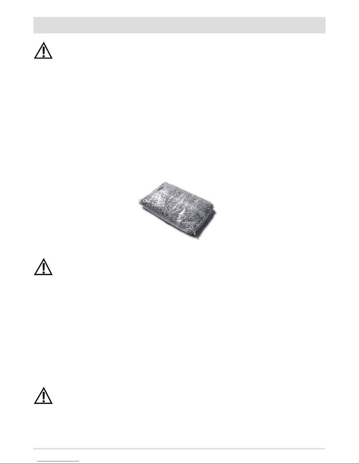
supplied in 15 kg bags, therefore, storing them is very convenient.
Good quality pellets guarantee good combustion, thereby decreasing harmful emissions into the atmosphere.
The poorer the quality of the fuel, the more often the internal parts of the brazier and combustion chamber must
be cleaned.
The main quality certications for pellets currently available on the European market guarantee that the fuel complies with class A1/A2
according to ISO 17225-2 (ex EN 14961). These certications include, for example, ENPlus, DINplus, Ö-Norm M7135, and in particular,
guarantee the following characteristics:
• caloric value: 4.6 ÷ 5.3 kWh/kg.
• Water content: ≤ 10% of the weight.
• Percentage of ash: max 1.2% of the weight (A1 less than 0.7%).
• Diameter: 6±1/8±1 mm.
• Length: 3÷40 mm.
• Content: 100% untreated wood without the addition of binding agents (max 5% bark).
• Packaging: in sacks made from ecologically compatible or biologically decomposing material.
The company strongly recommends using certied fuel for its products (ENplus, DINplus, Ö-Norm M7135).
Poor quality pellets or others that do not comply with the characteristics specied previously may compromise the
operation of your product and can therefore make the guarantee and product liability invalid.
BAG OF PELLETS 15 kg
Page 12
10
2-INSTALLATION
PRECAUTIONS REGARDING INSTALLATION
IMPORTANT!
Product installation and assembly must be carried out by qualied personnel.
The product must be installed in a suitable place that allows easy access for it to be opened regularly and for routine maintenance to be
performed.
The installation area must be:
• suitable to enable the appliance to operate correctly.
• Equipped with an adequate smoke expulsion system.
• Equipped with adequate ventilation from outside.
• Equipped with 230V 50 Hz power supply with an EC compliant earthing system.
IMPORTANT!
The product must be connected to a chimney that expels the smoke at the highest point of the building.
The chimney must be of suitable dimensions, caulked, and tted with a condensation collector for collecting the
water vapour that can form due to the high performance of the appliance and the consequently low temperatures
of the outgoing fumes.
The chimney must comply with regulations in force.
The holes of the external air inlet and the smoke outlet pipe must be drilled before positioning the product.
THE OPERATING AREA
The boiler must be installed indoors in an area well protected from atmospheric elements.
The surface on which it stands and/or support points must have sucient load bearing capacity to support the total weight of the
appliance, its accessories and covers.
To ensure the appliance works well, we recommend installing the boiler detached from any walls or furniture, and with good air circulation
to allow eective ventilation for the appliance. The product should be located in an area that allows sucient space for normal use and
maintenance operations.
The volume of the room should be no less than 15 m
3
.
It is essential that an adequate outdoor air intake is provided that supplies the air for combustion needed for the product to function
correctly.
These air inlets must be arranged so that it is impossible for them to be obstructed.
Protect the inlets with grilles, metal mesh, etc., without reducing the net cross-section.
Remember that the ventilation grilles always have the useful cross-section in cm
2
indicated on one side. When
choosing the grille and size of the inlet, check that the useful cross-section of the grille is larger or equal to the
section required for product operation.
The ow of air between the outside and the room of installation may be direct, through an inlet in an external wall of the building; or
indirect, through the intake of air from rooms adjoining and connecting permanently with the room of installation. Adjoining areas may
not include sleeping areas, garages or general areas that present a re hazard.
For air ducts, up to 3m increase the cross-section by approximately 5%, while for ducts that run for longer increase it by 15%.
IMPORTANT!
The air ow can also be drawn from an adjoining room to that of the room where the product is installed, provided
the air can ow freely through permanent openings to the outside; avoid connection to sleeping areas and rooms
that present a re hazard in general.
Page 13
11
2-INSTALLATION
Technical Dept. - All rights reserved - Reproduction is prohibited
POSITIONING AND RESTRICTIONS
In the case of simultaneous installation with other heating appliances, provide appropriate air inlets for each one (according to the
instructions of each product).
Installation of the product is not permitted:
• in rooms where there are liquid fuel appliances with continuous or intermittent operation that draw the
combustion air from the room they are installed in;
• in rooms where there are B-type gas heating appliances, with or without domestic hot water production and
interconnecting rooms;
• in rooms in which the decrease in pressure during use, as measured between the pressure outside and the
pressure in the room, is greater than 4 Pa.
The product may not be installed in rooms used as sleeping areas, bathrooms, garages or in rooms that present a
re hazard in general.
BOILER ROOM
Check that the room meets the requirements and provisions of the standards in force. There must also be a ow of at least enough air in
the room for normal combustion. Vents must be installed in the walls of the room that meet the following requirements:
• Increase the cross-section by at least 6 cm
2
for each 1 kW (859.64kcal/h) The minimum cross-section of the opening must not,
however, measure less than 100 cm
2
. The cross-section can be calculated using the following relations:
S = K * Q ≥ 100 cm
2
Where “S” is in cm2, “Q” in kW, “K” = 6 cm2/kW
• The opening must be located at the base of an external wall, preferably opposite the one with the outlet for combusted gases.
Heat-sensitive or ammable objects cannot be stored near the product; keep such objects at a minimum distance of
80 cm from the outermost point of the product.
CONNECTION OF THE SMOKE EXHAUST DUCT
When making the hole for the passage of the smoke discharge pipe, it is necessary to take into account the possible presence of ammable
materials. If the hole has to be in a wall made of wood or other thermolabile material, THE INSTALLER MUST rst set up the relative wall
tting (diameter 13 cm minimum) and insulate the pipe of the product passes with appropriate insulating material (1.3 - 5 cm thick with
minimum heat conductivity of 0.07 W/m°K).
The same minimum distance must be applied if the pipe of the product must pass through vertical or horizontal sections near the
thermolabile wall.
It is recommended to use an insulated double-wall pipe in external sections in order to prevent condensation from forming.
The combustion chamber works in negative pressure.
Page 14
min.3,5 metri
AT
(A)
AP
(B)
12
2-INSTALLATION
FOREWORD
The Chimney Flue chapter has been drawn up with reference to the provisions of European Standards (EN13384 - EN1443 - EN1856 EN1457).
The chapter provides indications for installing an ecient and correct ue but is under no circumstances to substitute the regulations in
force, which the qualied technician must be in possession of. Check with local authorities whether there are any restrictive regulations in
force regarding the intake of air for combustion, the smoke extraction system, the ue or the chimneypot.
The company declines all liability relating to the poor functioning of the boiler if this is due to the use of an insuciently sized ue in
violation of the Standards in force.
FLUE
Have the eciency of the ue checked by an authorised technician.
The ue or chimney is vital to the correct functioning of a forced draft solid fuel heating appliance, given that boilers with high performance
have cooler fumes with consequently weaker draft and the possible formation of condensation.
It is therefore essential that the ue meets all construction standards and is always maintained in perfect condition.
A ue that serves a pellet/wood fuelled appliance must be at least category T400 (or greater if the appliance requires so) and resistant to
soot res. Smoke must be extracted through a single ue made of insulated steel (A) or an existing ue that complies with the intended
use (B).
A simple air shaft made of cement must be suitably lined. In either case, ensure to include an inspection cap (AT) or inspection door (AP)
and a suitable device for collecting condensation - FIG.1.
It is prohibited to connect more than one wood/pellet (*) or any other type of appliance (vent cowling...) to the same ue.
(*) unless there are national derogations (for instance in Germany), which under suitable conditions allow for the installation of several
appliances in the same replace. In any case, strictly follow the product/installation requirements of the relative regulations/legislation
in force in that country
.
FIGURE 1 - FLUE
Page 15

A
B
C
D
E
A
B
C
D
15°
E
F
13
2-INSTALLATION
Technical Dept. - All rights reserved - Reproduction is prohibited
TECHNICAL CHARACTERISTICS
Flues serving a pellet/wood fuelled appliance must meet the following requirements:
• made of materials that are suciently resistant to mechanical stress, heat, the action of the products of combustion and their
vapours.
• made of materials that are impermeable to fumes, condensation, be thermally insulated and resistant to normal mechanical stress
over time
• go in a vertical direction and deviate no more than 45° from the vertical axis and be free of choke points
• be suited to the specic operating conditions of the product and have CE marking (EN1856-1, EN1443).
• Be of the correct size to suit the draft/smoke extraction requirements necessary for the product to work properly (EN13384-1)
• Be suitably caulked externally to avoid condensation and reduce the cooling of the smoke.
• Be at least category T400 (or greater if the appliance requires) and resistant to soot res.
We recommend in particular to check on the data tags of the ue (in accordance with EN1856-1, EN1443) the safety distances that must
be respected in presence of passing combustible materials and the type of insulating material to be used. These indications must be
followed rigorously to avoid serious harm to personnel and surrounding infrastructure.
The chimney opening must be in the same room as the appliance, or at most in the adjoining room, and have a soot and condensation
collection chamber beneath the opening, and be accessible via a sealed metal hatch.
Smoke must be extracted through a single ue (see g. 3) with insulated steel tubes (A) or though an existing ue that complies with
the intended use (B). A simple air shaft in cement must be suitably lined. In either case, ensure to include an inspection cap (AT) and/or
inspection door (AP) and a suitable device for collecting condensation - FIG.1.
It is prohibited to connect more than one wood/pellet or any other type of appliance (vent cowling...) to the same ue.
FLAT ROOF
ROOF AT 15°
A = 0.50 metres
B = DISTANCE > 2 metres
C = DISTANCE < 2 metres
D = 0.50 metres
E = TECHNICAL VOLUME
A = MIN. 1.00 metres
B = DISTANCE > 1.85 metres
C = DISTANCE < 1.85 metres
D = 0.50 metres ABOVE HIGHEST
POINT
E = 0.50 metres
F = REFLUX AREA
FIGURE 2
FIGURE 3
Page 16

A
B
D
60°
E
C
F
A
B
C
D
E
45°
F
A
B
C
D
E
30°
F
14
2-INSTALLATION
ROOF AT 30°
ROOF AT 45°
ROOF AT 60°
A = MIN. 2.60 metres
B = DISTANCE > 1.20 metres
C = DISTANCE < 1.20 metres
D = 0.50 metres ABOVE HIGHEST
POINT
E = 2.10 metres
F = REFLUX AREA
A = MIN. 2.00 metres
B = DISTANCE > 1.30 metres
C = DISTANCE < 1.30 metres
D = 0.50 metres ABOVE HIGHEST
POINT
E = 1.50 metres
F = REFLUX AREA
FIGURE 6
FIGURE 4
A = MIN. 1.30 metres
B = DISTANCE > 1.50 metres
C = DISTANCE < 1.50 metres
D = 0.50 metres ABOVE HIGHEST
POINT
E = 0.80 metres
F = REFLUX AREA
FIGURE 5
Page 17

15
2-INSTALLATION
Technical Dept. - All rights reserved - Reproduction is prohibited
SIZING
The draught of a ue depends on its height. Check the draught with the values indicated in the technical characteristics. The minimum
height of the chimney is 3.5 metres.
The interior cross-section of the ue can be round (best), square or rectangular (the ratio between the internal sides must be ≤1.5) with
the sides joined with a minimum radius of 20 mm. The dimension of the cross-section must be a minimum Ø150mm.
The cross-sections/lengths of the chimneys shown in the technical data tables are indications for correct installation. Any alternative
congurations must be correctly sized in accordance with the general method of calculation of UNI EN13384-1 or other proven eciency
methods.
Below is a list of some ues available on the market:
AISI 316 steel chimney with
double chamber insulated with
ceramic bre or equivalent
resistant up to 400°C.
Refractory chimney with
double insulated chamber and
external lightweight concrete
cladding with cellular material
such as clay.
Traditional square-section clay
chimney with insulating empty
inserts.
Avoid products with an internal
rectangular section where the
larger side is 1.5 times the
smaller side (e.g. 20x40 or
15x30).
EXCELLENT GOOD POOR VERY POOR
Page 18

1
9
9
2
3
4
5
6
7
8
9
16
2-INSTALLATION
MAINTENANCE
The ue must always be kept clean, since the deposit of soot or unburned oils reduces the cross-section reducing the draft and thus
compromising the ecient operation of the boiler and, if large build-ups accumulate, they can catch re. The ue and chimneypot must
be cleaned and checked by a qualied chimney sweep at least once a year. Once the inspection/maintenance has been performed, request
a written report that the system is safe.
Failure to perform cleaning jeopardises the system’s safety.
CHIMNEYPOT
The chimneypot is a crucial element for the heating appliance to work properly: we recommend a wind proof chimneypot (A), see Figure 7.
The area of the opening for smoke
extraction must be at least double the
cross-section of the ue/lined system,
and arranged so that smoke extraction is
ensured even in strong wind. The chimney
must prevent rain, snow or animals from
entering the chimney. The height of
outow into the atmosphere must be
beyond the reux area due to the shape of
the roof or any obstacles near the outlet
(see Figures 2-3-4-5-6).
CHIMNEY COMPONENTS
LEGEND:
(1) CHIMNEYPOT
(2) REFLUX CHANNEL
(3) SMOKE DUCT
(4) THERMAL INSULATION
(5) OUTSIDE WALL
(6) CHIMNEY FITTING
(7) SMOKE DUCT
(8) HEAT GENERATOR
(9) INSPECTION ACCESS PANEL
FIGURE 7
FIGURE 8
Page 19

17
2-INSTALLATION
Technical Dept. - All rights reserved - Reproduction is prohibited
CONNECTION TO THE FLUE
The connection between the ue and the appliance must be via a smoke duct that complies with EN 1856-2. The connecting section must
extend no more than 4 m horizontally, with a minimum slope of 3% and with a maximum of 3 90% bends (accessible for inspection - do
not count the T tting at the appliance outlet).
The diameter of the smoke duct must be equal to or greater than that of the outlet of the appliance (Ø 100 mm).
TYPE OF SYSTEM SMOKE DUCT
Minimum vertical length 1.5 metres
Maximum length
(with 1 accessible 90° bend)
6.5 metres
Maximum length
(with 3 accessible 90° bends)
4.5 metres
Maximum number of accessible 90° bends 3
Horizontal sections
(minimum slope 3%)
4 metres
Use smoke ducts with a diameter 100 mm and silicone gaskets or similar gaskets that can withstand the high operating temperatures
of the appliance (min. T200 class P1). The use of exible metal hoses made of bre cement or aluminium is forbidden. For
direction changes, we always recommend the use of a T tting with an inspection cap ensuring easy access to clean the pipes.
Always ensure that the inspection cap is put back in place and sealed hermetically with the relevant seal intact after cleaning.
It is prohibited to connect more than one appliance to the same smoke duct, or the discharge from hoods above it. It is forbidden to extract
the combustion products directly through the wall, whether into indoor spaces or outdoors.
The smoke duct must be at a minimum distance of 400 mm from ammable or heat-sensitive structures.
We especially recommend to check the data tags of the ue for the safety distances that must be observed in presence of
combustible materials and the type of insulating material to be used. These indications must be followed rigorously to
avoid serious harm to personnel and surrounding infrastructure.
Page 20

T
I
S
I
U
B
A
P
U
I
I
C
4
3
D
2
I
E
V
U
1
F
18
2-INSTALLATION
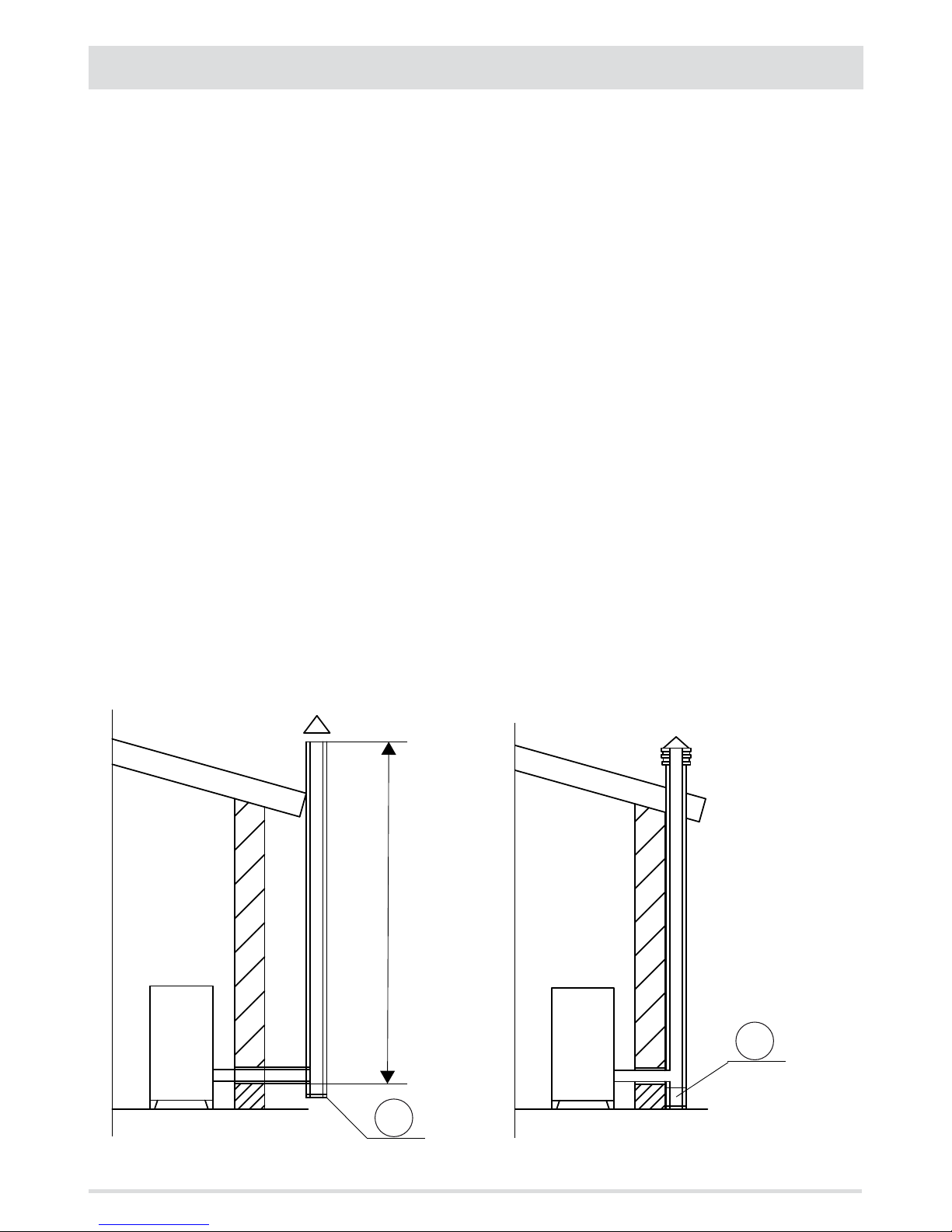
EXAMPLES OF CORRECT INSTALLATION
1. Installation of Ø 150 mm ue with hole for the passage
of the pipe increased by:
minimum 100mm around the pipe if next to non
ammable parts such as cement, brick, etc.; or
minimum 300mm around the pipe (or as required by
rating plate) if next to ammable parts such as wood etc.
In both cases, install suitable insulation between the ue
and the ceiling.
Always check and respect the data tags on the ue,
in particular the minimum safety distances from
combustible materials.
The previous rules also apply for holes made in walls.
2. Old ue, minimum tube Ø150mm with the inclusion of
an external access door for chimney cleaning.
3. External ue made of insulated stainless steel pipes,
i.e. with double walls minimum Ø150mm: all securely
mounted to the wall. With windproof chimneypot. See
g. 7 type A.
4. Ducting system using T ttings that allow easy access
for cleaning without having to remove the pipes
FIGURE 11
U = INSULATING
V = ANY REDUCTION FROM 100 TO 80 MM
I = INSPECTION CAP
S = INSPECTION ACCESS PANEL
P = AIR INLET
T = T JOINT WITH INSPECTION CAP
A = MINIMUM 40 MM
B = MAXIMUM 4 M
C = MINIMUM 3°
D = MINIMUM 400 MM
E = HOLE DIAMETER
F = SEE FIG.2-3-4-5-6
Page 21

743
605
1321
429
393
109
486
Ø80
Ø100
19
3-DRAWINGS AND TECHNICAL FEATURES
Technical Dept. - All rights reserved - Reproduction is prohibited
DRAWINGS AND CHARACTERISTICS
PERFORMA 25/30 BOILER DIMENSIONS
Page 22

20
3-DRAWINGS AND TECHNICAL FEATURES
TECHNICAL CHARACTERISTICS PERFORMA 25 PERFORMA 30
Product class (EN 303-5/2012)
5 5
Rated thermal capacity of the rebox
25.1 kW (21586 kcal/h) 30.3 kW (26058 kcal/h)
Nominal output power:
23.2 kW (19952 kcal/h) 27.4 kW (23564 kcal/h)
Minimum output power
5.5 kW (4730 kcal/h) 5.5 kW (4730 kcal/h)
Eciency at Max
92.3% 90.4%
Eciency at Min
91.8% 91.8%
Temperature of exhaust smoke at Max
83°C 84°C
Temperature of exhaust smoke at Min
53°C 53°C
Max congurable temperature
80°C 80°C
Max operating temperature
85°C 85°C
Particles/OGC/Nox (10%O2)
14 mg/Nm3 - 2 mg/Nm3 - 165 mg/Nm
3
13 mg/Nm3 - 2 mg/Nm3 - 170 mg/Nm
3
CO at 10% O2 at Min and at Max
0.011 - 0.010% 0.011 - 0.009%
CO2 at Min and at Max
7.8 - 11.4% 7.8 - 11.6%
Recommended draught at Max power
0.10 mbar - 10 Pa 0.10 mbar - 10 Pa
Recommended draught at Min power
0.05 mbar - 5 Pa 0.05 mbar - 5 Pa
Smoke mass
15.6 g/sec 18.3 g/sec
Tank capacity
100 litres 100 litres
Type of pellet fuel
Pellet diameter 6-8 mm and size 3/40
mm
Pellet diameter 6-8 mm and size 3/40 mm
Pellet hourly consumption
Min ~ 1.2 kg/h* - Max ~ 5.1 kg/h* Min ~ 1.2 kg/h* - Max ~ 6.2 kg/h*
Autonomy
Min H ~ 54 h - Max. H ~ 13 h Min H ~ 54 h* - Max H ~ 10 h*
Heatable volume m
3
499/40 - 570/35 - 665/30** 589/40 - 673/35 - 785/30**
Moisture content
38 litres 38 litres
Max operating temperature
3 bar - 300 kPa 3 bar - 300 kPa
Combustion air inlet
80 mm 80 mm
Smoke outlet
100 mm 100 mm
Air inlet
100 cm
2
100 cm
2
Rated electrical power (EN 60335-1)
85 W (Max 470 W) 85 W (Max 470 W)
Supply voltage and frequency
230 Volt / 50 Hz 230 Volt / 50 Hz
Net weight
265 kg 265 kg
Weight with packaging
280 kg 280 kg
* Data that may vary depending on the type of pellets used.
** Volume that can be heated, according to the power requirement in m
3
(respectively 40-35-30 Kcal/h per m3)
Page 23

0
20
40
60
80
100
120
140
160
180
200
220
240
260
280
300
320
340
360
380
400
420
440
460
480
500
0 50 100 150 200 250 300 350 400 450 500 550 600 650 700 750 800 850 900 950 1000
A = PRESSURE HEAD (mbar) prevalenza
B = FLOW RATE (dm3/h)
0
20
40
60
80
100
120
140
160
180
200
220
240
260
280
300
320
340
360
380
400
420
440
460
480
0 50 100 150 200 250 300 350 400 450 500 550 600 650 700 750 800 850 900 950 1000 1050 1100
B = FLOW RATE (dm3/h)
A = PRESSURE HEAD (mbar) prevalenza
21
3-DRAWINGS AND TECHNICAL FEATURES
Technical Dept. - All rights reserved - Reproduction is prohibited
RESIDUAL HEAD CHART WITH HYDRAULIC KIT FOR HEATING
RESIDUAL HEAD CHART WITHOUT HYDRAULIC KIT FOR HEATING
A = RESIDUAL HEAD (mbar)
B = FLOW (dm3/h)
Page 24

S
S
x
y
x
y
S
22
4-INSTALLATION AND ASSEMBLY
PREPARATION AND UNPACKING
The Performa is delivered complete with all its electrical, mechanical and hydraulic components (excluding the circulator
kit -OPTIONAL) and having been tested in the factory.
The boiler is delivered in a single package and the packaging of the selected hydraulic kit - optional accessory is added after.
Remove the cardboard, remove the S-brackets that secure the boiler to the pallet as well as the “x” and “y” screws. There are two S-xing
brackets, one at the front and one at the back.
Install the boiler in the area set aside for it, making sure it conforms to the
requirements. The boiler body or unit must always be kept in a vertical position
when moved, and only ever moved using suitable lifting trolleys.
The packaging materials are neither toxic nor harmful, and therefore no
particular disposal measures are required.
After removing all the packaging, check that the boiler is complete and not
damaged. If in doubt, contact the retailer.
FIGURE 1 - PACKAGING
FIGURE 2 - REMOVING THE PACKAGE BRACKETS
Page 25

U
I
23
4-INSTALLATION AND ASSEMBLY
Technical Dept. - All rights reserved - Reproduction is prohibited
The end user is responsible for product storage, disposal or possible recycling in compliance with the relative applicable
laws in force. Position the product and proceed with connecting it to the chimney.
If the product must be connected to an exhaust pipe that goes through the rear wall (to enter the chimney), make sure not to force it in.
Attention!!
If the boiler smoke outlet is forced or used improperly to lift it or position it, the operation of the stove can be
damaged irreparably.
U = SMOKE OUTLET DIAMETER 100 MM
I = COMBUSTION AIR INLET DIAMETER 80 MM
Page 26

1321
1000
500500
605
500
500
605
1000
743 500
24
4-INSTALLATION AND ASSEMBLY
REQUIREMENTS FOR INSTALLATION OF THE PLANT - POSITIONING
The most important thing to do before installation of the boiler is to set aside a suitable area that meets the minimum requirements for
installation.
• the minimum clearance in front of the product for the purpose of cleaning, maintenance, etc. must be 1000 mm;
• the minimum permissible distance between the back of the product and a wall must be 500 mm;
• the minimum distance between the top of the product and a wall (ceiling) must be 1000 mm to ensure easy access to the heat
exchanger for cleaning and maintenance (e.g. for removing ash and possible installation of the pellet suction kit);
• the minimum clearance between the product and the wall (side) must be 500 mm
Page 27

y
A
D
C
B
x
25
5-REMOVING THE AESTHETICS
Technical Dept. - All rights reserved - Reproduction is prohibited
Live electrical parts: only power the product once it has been fully assembled.
If any work is carried out on some components of the boiler or if you are just cleaning it, you need to remove the side panels.
To remove the right panel “D” proceed as follows:
• lift the tank cover “C”
• lift the front cover “B”
• open the decorative door “A”
• remove the two top screws “x” that secure the panel “D” to the boiler
• lift the panel “D” and let the joints “k” come out of the holes “y” on the structure of the boiler (see image on the following page)
Page 28

k
D
26
5-REMOVING THE AESTHETICS
Page 29

E
A
C
B
x
27
5-REMOVING THE AESTHETICS
Technical Dept. - All rights reserved - Reproduction is prohibited
REMOVING THE LEFT SIDE PANEL
Remove the left side panel “E” by following the instructions for the right side panel. Unlike panel “D”, panel “E” is whole.
Page 30

B
B
v
u
R
28
5-REMOVING THE AESTHETICS
FRONT DOOR
The front door “B” is provided with a limit switch for its opening, so as to prevent the pellet from falling on the door.
REAR COVER FOR THE HYDRAULIC KIT
The back of the boiler has a removable cover to insert the selected hydraulic kit. Remove cover “R” by loosening the two upper screws and
lifting the cover so as to release the joint “u” of the cover from the “v” joint of the boiler.
Page 31

94 127 123
119
2
6
7
8
29
6-HYDRAULIC CONNECTION
Technical Dept. - All rights reserved - Reproduction is prohibited
HYDRAULIC CONNECTION
IMPORTANT:
The connections depend on the type of System Conguration.
IMPORTANT!
If installing the boiler involves another pre-existing system complete with heating equipment (gas boiler, methane
boiler, fuel oil boiler, etc.), it is strongly recommended that you contact a qualied operator who subsequently will
be responsible for the compliance of the system with the applicable laws in force.
The Company will not be held responsible for damage to persons or things in the event of failed or incorrect operation
if the aforementioned warnings are not complied with.
IMPORTANT!!!
CLEAN THE ENTIRE SYSTEM BEFORE CONNECTING THE BOILER, IN ORDER TO REMOVE ALL RESIDUE AND DEPOSITS.
Upstream from the boiler, always install shutters so as to disconnect it from the plumbing system should it be
necessary to move it, or when it requires routine and/or special maintenance.
Connect the boiler using hoses so that the boiler is not too strictly connected to the system, and to allow slight
movements.
IMPORTANT!
The connection of the stove to the plumbing system must be carried out ONLY by specialized personnel who are
capable of carrying out installation properly, in compliance with current standards in the country of installation.
The manufacturer will not be held responsible for damage to persons or things in the event of failed operation if the
aforementioned warning is not complied with..
CONNECTION DIAGRAM WITH HYDRAULIC KIT FOR HEATING (SEE ACCESSORY CODE 40A16002)
2 - SAFETY VALVE 7 - HEATING DELIVERY
6 - HEATING RETURN 8 - SYSTEM FILLING WATER INLET
Page 32

95 128 122
119
119
50
4
5
2
6
7
30
6-HYDRAULIC CONNECTION
CONNECTION DIAGRAM WITH HYDRAULIC KIT FOR DHW PRODUCTION (SEE ACCESSORY CODE 40A16003)
2 - SAFETY VALVE 5 - DOMESTIC WATER INLET
3 - FILLING TAP 6 - HEATING RETURN
4 - DOMESTIC WATER OUTLET 7 - HEATING DELIVERY
Page 33

Valvola di Sicurezza 3 bar CE
PN10, TMAX 110°C
Attenzione! T 110°C
2
31
6-HYDRAULIC CONNECTION
Technical Dept. - All rights reserved - Reproduction is prohibited
SAFETY VALVE 3 bar
The boiler is protected against overpressures by a safety valve “2” tted on the selected hydraulic kit. The safety valve drain must be
connected to a rubber pipe that can withstand a temperature of 110°C (not supplied) and that reaches the outside via an anti-odour
syphon. This drain is provided in order to prevent overpressures if the safety valve is opened.
Attention! The manufacturer of the appliance is not liable for any ooding caused by the safety valve being triggered
if it has not been joined properly to the outside of the product and to a proper collection and evacuation system.
Page 34

32
6-HYDRAULIC CONNECTION
CLEANING THE SYSTEM
Install suitable shutters to cut o the tubes from the heating system.
In order to protect the heating system from damage caused by corrosion, incrustation or deposit build-up, it is important to clean the
appliance before installation, using suitable products, in compliance with Standard UNI 8065 (water treatment of thermal plants for civil
use).
The use of FERNOX PROTECTOR F1 (available at our authorised centres) product is recommended, this provides long-term protection of
heating systems against corrosion and calcium build-up. It prevents the corrosion of the metal parts of the appliance, i.e. the ferrous
metals, copper and copper and aluminium alloys. It also reduces the noise produced by the boiler. Refer to the instructions on the product.
Cleaning should be performed by a qualied technician.
We also recommend the use of FERNOX CLEANER F3 and LEAK SEALER F4, available from our authorised distribution centres.
FERNOX F3 is a neutral product for rapid and ecient cleaning of heating appliances. It has been designed to eliminate residues, oily
deposits and incrustations from existing appliances of all ages. It can help restore the heating eciency of the boiler and reduce the noise
it generates.
FERNOX F4 is intended to be used with all heating appliances to seal micro fractures that cause small and inaccessible leaks.
Attention: Failure to clean the thermal system or to use an adequate inhibitor will invalidate the warranty of the
appliance and of the other accessories like the pump and valves.
FILLING THE SYSTEM
Fill the system slowly to allow air bubbles to pass through the vent holes of the heating system. For closed circuit heating systems, the
lling pressure of the system at cold and the pre-ination pressure of the expansion tank must be the same.
• In open vessel heating systems, direct contact between circulating liquid and air is allowed. During the heating season, the user
must check the circulating water level in the expansion tank regularly. The water level in the circulation system must be kept
constant. Practical experience shows that a regular check of the water level must be made every 14 days to maintain a relatively
constant level. When necessary, the water level must be topped up when the boiler has cooled to room temperature. This is to avoid
and damage being caused to the steel body of the boiler due to thermal stress.
• In systems with an open vessel, the water pressure in the boiler must not be less than 0.3 bar when the system is cool.
• The water used for lling the heating system must be decontaminated and not contain air.
Attention!
Do not mix heating water with incorrect concentrations of anti-freeze or anti-corrosion substances! This could
damage the gaskets and cause noise during operation.
The manufacturer denies any liability for harm caused to persons, animals or objects caused by failure to observe
these precautions.
After making all the hydraulic connections, pressure-test the seals by lling the boiler.
This must be done with care by doing the following:
• open the air vent valves of the radiators, boiler and system;
• gradually open the lling tap of the system, making sure that any automatic air vent valves in the system work correctly;
• close the vent valves of the radiators as soon as water comes out;
• use the pressure gauge inserted in the system to check that the pressure reaches a value of approximately 1 bar (this only applies to
closed vessel systems - refer to any existing local regulations or standards allowing for its installation); for open vessel systems, the
water is topped up automatically through the vessel.
• close the lling tap of the system and then open the vent valves of the radiators again to purge any air;
• check the seal of all the connections;
Page 35

G
H
I
33
6-HYDRAULIC CONNECTION
Technical Dept. - All rights reserved - Reproduction is prohibited
• after starting up the boiler for the rst time and bringing the system up to temperature, stop the pumps and repeat the air purging
procedure;
• let the system cool down and, if necessary, bring the water pressure back to 1 bar (this only applies to closed vessel systems - refer to
any existing local regulations or standards allowing for its installation); for open vessel systems, the water is topped up automatically
through the vessel itself;
NOTE
In systems with a closed vessel, where possible, the water pressure in the heating system must not be lower than 1
bar when the system is at room temperature; if this is not the case, use the tap to ll the system. This operation must
be performed when the system is cool.
The pressure gauge on the system enables you to read the pressure in the circuit.
During this operation, any air in the system is released from the automatic vent “G” at the top of the body of the boiler.
The valve is underneath the front panel, just lift the cover.
To ensure the valve vents, loosen the side cap (see gure)
The lling pressure of the system WHEN COLD must be 1 bar.
Upon completion of this operation, always close the lling tap.
RELIEF VALVE “G”
Page 36

m
34
6-HYDRAULIC CONNECTION
PRESSURE GAUGE
The gauge of the boiler “m” is one of the key tools, which is used to check that appliance is operating smoothly. The pressure gauge of the
boiler is used to measure the pressure, i.e. the dierence between the internal pressure and the atmospheric pressure. Generally, the ideal
pressure for a boiler is between 1.5 and 2 bar, above or below which malfunctions occur in the heating system or in the supply of domestic
hot water. The pressure adjustments are made through the vent valve “G” at the top of the boiler (see instructions on the previous page).
Low boiler pressure
When the pressure of the boiler is too low, and therefore it is indicated on the pressure gauge as below 1.5 bar, the heating does not work
well, hot water does not arrive or the boiler is blocked. The main reasons that lower the pressure are:
• Temperature too low, which causes the condensation to form
• Air in the pipes
• A fault in the 3-way valve
High boiler pressure
If the pressure is high, that is the boiler pressure gauge marks more than 2 bar, the energy eciency of the boiler decreased, which means
that the consumption increases.
Page 37

35
7-ELECTRICAL CONNECTION
Technical Dept. - All rights reserved - Reproduction is prohibited
GENERAL PRECAUTIONS
The electrical safety of the system is guaranteed only when this is connected correctly to an ecient earthing system installed in
accordance with the safety standards in force: the pipes of the gas, water and heating systems do not constitute a suitable earth system.
It is necessary to ensure this essential safety requirement; if in doubt, have a qualied technician test the electrical system with care
because the manufacturer of the boiler does not assume responsibility for damage caused by the absence of an earthing system.
A qualied technician should check that the electrical system is compatible with the max consumption of the system, checking in
particular that the cross-section of the cables of the system is compatible with the power consumption of the loads.
The use of any component that requires electrical energy requires compliance with certain essential rules like:
• do not touch the appliance with wet and/or damp parts of the body and/or when barefoot;
• do not pull on the electrical cables;
• do not expose the appliance to the elements (rain, sun, etc.);
• do not allow children or inexperienced persons to use the appliance.
Connection to 230V power supply.
The installation of additional electrical components of the boiler requires electrical connection to a 230V - 50Hz power supply: This
connection must be made in a workmanlike manner in compliance with the standards in force in the country of installation.
Danger!
Electrical installation must be entrusted to a single qualied technician.
Before making the connections or carrying out any work on the electrical parts, always turn o the power supply
and make sure it cannot be turned on again accidentally.
Remember that it is necessary to install a bipolar switch in the boiler’s electrical power circuit with a distance of
3mm between the main contacts. The switches must be easily accessible to allow quick and safe maintenance.
The power cable must be replaced only by an authorised technician. Failure to observe the above could compromise the safety of the unit.
ELECTRICAL CONNECTION
First connect the power cable to the back of the boiler and then to a wall socket.
The main switch at the rear must only be activated to switch the boiler on; otherwise, it is advisable to keep it o.
It is recommended to disconnect the power cable when the boiler is not used.
ELECTRICAL CONNECTION
Page 38

36
8-FIRST START-UP
BEFORE START-UP
GENERAL PRECAUTIONS
Remove all parts that may burn from the brazier and the product’s tank (manual, various adhesive labels or any polystyrene).
The rst start-up may not be successful as the feed screw is empty and does not always manage to load the brazier
with the required amount of pellets in time to light the ame.
CANCEL THE FAILED IGNITION ALARM. REMOVE THE PELLETS LEFT IN THE BRAZIER AND REPEAT THE START-UP.
If after repeated attempts, the ame fails to ignite, despite a regular ow of pellets in the brazier, verify that the brazier is assembled
correctly and must be clean without any ash incrustations. If no anomaly is found during this inspection, there may be a problem
with the product components or installation may not be correct.
REMOVE THE PELLETS FROM THE BRAZIER AND CONTACT AN AUTHORISED TECHNICIAN.
Do not touch the boiler during the rst lighting, as it is during this phase that the paint sets; if you touch the paint,
you may expose the steel surface.
If necessary, touch up the paint with the aerosol spray in the original colour (see ‘’Accessories for pellet boilers’’).
It is good practice to guarantee eective ventilation in the room during the initial start-up, as the boiler will emit
some smoke and smell of paint.
ATTENTION!
Please ensure the brazier is clear of ALL pellets and ash build up following any failed ignitions. Failure to clear out
the brazier prior to resetting may result in further failed ignitions or in certain conditions an explosive ignition.
Do not stand close to the boiler and ventilate the room as described. The smoke and smell of paint will disappear after about an hour of
operation, however, they are not harmful in any case.
The boiler will be subject to expansion and contraction during the stages of lighting and cooling down, and may therefore make slight
creaking noises.
This is absolutely normal as the structure is made of laminated steel and must not be considered a defect.
It is extremely important to make sure the boiler does not reach high temperatures straight away, but to increase the temperature
gradually using low power at rst.
DO NOT EXPECT HEATING EFFICIENCY IMMEDIATELY!!!
ATTENTION!
If during operation or initial ignition you encounter combustion smoke spillage in to the room from the
appliance or the ue then please switch o the appliance, ventilate the room and contact the installation
/ service technician immediately.
Page 39

A
T
37
8-FIRST START-UP
Technical Dept. - All rights reserved - Reproduction is prohibited
OPENING/CLOSING
ATTENTION!
The door must be closed properly for the boiler to work correctly.
The rebox door and the lower door for cleaning the ash must only be opened with the boiler coil and o.
If the doors are opened while the boiler is running, a system will trigger the alarm and the boiler will go o.
Open the outer door “A” by grasping the handle at the top right and pull towards you. Open the internal door “T” by lifting and pulling the
handle towards yourself. In the event one needs to open the door with the boiler in operation, one must use suitable thermal protection
clothing (for example leather gloves).
Page 40

C
u
V
38
8-FIRST START-UP
LOADING THE PELLETS
The pellets can be loaded either manually or automatically. The empty tank can contain up to 100 litres or 65 kg of pellets.
Manual Loading:
• Open the top door “C” of the boiler directly and pour in the pellets.
Automatic loading (with remote tank of 200/400 or 300 kg - optional - see accessories):
• Remove the round “V” plate from the door by removing the two “u” screws and disconnecting the insulation and inserting the tank
pipe. Next, load with the optional tank.
Never remove the protective grate from inside the tank. When loading pellets, keep the bag from coming into
contact with hot surfaces.
Page 41

39
8-FIRST START-UP
Technical Dept. - All rights reserved - Reproduction is prohibited
SAFETY
PROCEDURE TO FOLLOW IF ANY SMOKE SPILLAGE IS SEEN WITHIN THE ROOM OR THE APPLIANCE SUFFERS FROM AN EXPLOSIVE
IGNITION PLEASE TURN OFF THE APPLIANCE, VENTILATE THE ROOM AND CONTACT THE INSTALLER/ SERVICE ENGINEER
IMIDIATLEY.
User Training
In ALL cases, the technician in charge of installation and rst-start-up MUST carry out a thorough handover of the
appliance to the homeowner / end user. The following elements should be covered to the satisfaction of the end user.
Failure to do this may result in unsafe use of the appliance:
• • Explanation of the appliance and how it works
• • Necessity to maintain ventilation to the appliance and the issues that may arise otherwise
• • Fuel useage and supply
• • How to light the appliance safely
• • What to do in the event of failed ignitions
• • What to do in the event of alarms (in particular those generated when the appliance runs out of fuel)
• • How to maintain the appliance correctly and the importance of carrying out these tasks each month
• • It is good practise to agree a date for the srt annual service
• • Explain the importance of the CO alarm in accordance with approved document J of the building regs (ONLY FOR UK)
• • Explain the need for the ue draft stabiliser and its position within the ue system (ONLY FOR UK)
• • Discuss the use of secondary heating systems if applicable
• • Explain how the remote control or room stats operate and their optimal positioning
• • Explain the need for the appliance data plate in accordance with approved document J of the building regulations (ONLY FOR UK)
• • The commissioning process and paperwork should also be explained to the homeowner. A copy of the base settings on the
• commissioning paperwork should also be left with the appliance (ONLY FOR UK).
Page 42

Page 43

Page 44

REV 08901624100
Via La Croce n°8
33074 Vigonovo di Fontanafredda (PN) – ITALY
Telefono: 0434/599599 a.s.
Fax: +39 0434/599598
Internet: www.red-re.it
e-mail: info@red-re.it
21/11/2016
 Loading...