


EN - For pricing and availability in your local country please visit one of the below links:
DE - Informationen zu Preisen und Verfügbarkeit in Ihrem Land erhalten Sie über die unten aufgeführten Links:
FR - Pour connaître les tarifs et la disponibilité dans votre pays, cliquez sur l'un des liens suivants:
CUB5SNK0
EN |
DE |
FR |
This Datasheet is presented by |
Dieses Datenblatt wird vom |
Cette fiche technique est |
the manufacturer |
Hersteller bereitgestellt |
présentée par le fabricant |
Bulletin No. CUB5-L Drawing No. LP0584 Released 04/16
Tel +1 (717) 767-6511
Fax +1 (717) 764-0839
www.redlion.net
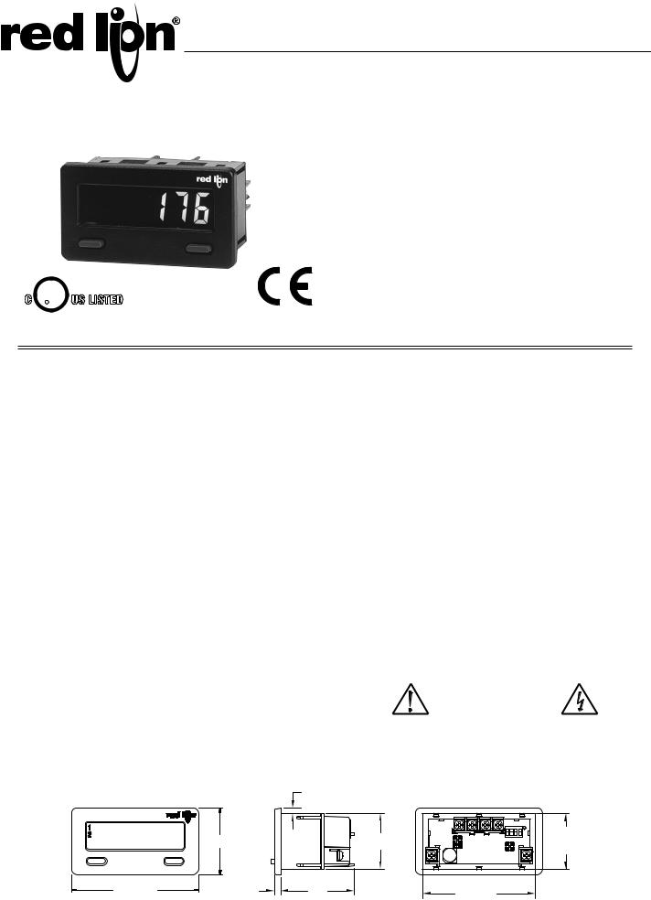
MODEL CUB®5 - MINIATURE ELECTRONIC 8-DIGIT DUAL COUNTER AND RATE INDICATOR
C UR L US LISTED
IND. CONT. EQ.
51EB
LCD, REFLECTIVE OR GREEN/RED LED BACKLIGHTING
0.46" (11.7 mm) HIGH DIGITS
OPTIONAL SETPOINT OUTPUT CARD
OPTIONAL SERIAL COMMUNICATIONS CARD (RS232 or RS485)
OPTIONAL USB PROGRAMMING CARD
OPERATES FROM 9 TO 28 VDC POWER SOURCE
PROGRAMMABLE SCALING FOR COUNT AND RATE
BI-DIRECTIONAL COUNTING, UP/DOWN CONTROL
QUADRATURE SENSING (UP TO 4 TIMES RESOLUTION)
BUILT-IN BATCH COUNTING CAPABILITY
DISPLAY COLOR CHANGE CAPABILITY AT SETPOINT OUTPUT
NEMA 4X/IP65 SEALED FRONT BEZEL
GENERAL DESCRIPTION
The CUB®5 provides the user the ultimate in flexibility, from its complete user programming to the optional setpoint control and communication capability. The meter can be programmed as a single or dual counter with rate indication capability. The display can be toggled either manually or automatically between the selected displays.
The CUB5 display has 0.46" (11.7 mm) high digits. The LCD is available in two versions, reflective (CUB5R000) and backlight (CUB5B000). The backlight version is user selectable for green or red backlighting with variable display intensity.
The counter is programmable for one of eight different count modes, including bi-directional and quadrature. When programmed as a dual counter, each counter has a separate scale factor and decimal points. In the counter/rate indicator mode, each have their own scaling and decimal point read-outs in different engineering units. The internal batch counter can be used to count setpoint output activations.
The meter has two separate inputs which provide different functions depending on which operating mode is selected. Input A accepts the signal for the Count and/or Rate displays, while Input B accepts the signal for the Count display or direction control. In the anti-coincidence mode, both inputs are monitored simultaneously so that no counts are lost. The resulting display can be chosen as the sum or difference of the two inputs. The Rate Indicator has programmable low (minimum) and high (maximum) update times to provide optimal display response at any input frequency. There is a programmable user input that can be programmed to perform a variety of functions.
The capability of the CUB5 can be easily expanded with the addition of option cards. Setpoint capability is field installable with the addition of the single setpoint relay output card or the dual setpoint solid state output card. Serial communications capability for RS232 or RS485 is added with a serial option card.
The CUB5 can be powered from an optional Red Lion Micro-Line/Sensor Power Supply (MLPS), which attaches directly to the back of a CUB5. The MLPS is powered from 85 to 250 VAC and provides up to 400 mA to drive the unit and sensors.
COUNTER
The CUB5 receives incoming pulses and multiplies them by the Count Scale Factor to obtain the desired reading for the count display. Input A accepts the signal for the count and Input B is used for quadrature, dual counter, anticoincidence counting, or up/down control counting.
RATE
The rate indicator utilizes the signal at Input A to calculate the rate value using a time interval method (1/tau). The unit counts on the negative edge of the input pulses. After the programmed minimum update time elapses and the next negative edge occurs, the unit calculates the input rate based on the number of edges that occurred during the elapsed time. The input rate is then multiplied by the rate scaling value to calculate the rate display.
At slower rates, averaging can be accomplished by programming the rate minimum update time for the desired response. Extensive scaling capabilities allow practically any desired reading at very slow count rates.
SAFETY SUMMARY
All safety related regulations, local codes and instructions that appear in this literature or on equipment must be observed to ensure personal safety and to prevent damage to either the instrument or equipment connected to it. If equipment is used in a manner not specified by the manufacturer, the protection provided by the equipment may be impaired.
Do not use this meter to directly command motors, valves, or other actuators not equipped with safeguards. To do so can be potentially harmful to persons or equipment in the event of a fault to the meter.
CAUTION: Risk of Danger. |
CAUTION: Risk of electric shock. |
Read complete instructions prior to |
|
installationand operation of the unit. |
|
DIMENSIONS In inches (mm) |
Note: Recommended minimum clearance (behind the panel) for mounting clip installation is 2.15" (54.6) H x 3.00" (76.2) W. |
|
.13 (3.3) |
9876543.2 |
1.54 (39.1) |
|
1.29 (32.8) |
|
|
SEL |
RST |
|
|
|
|
|
2.95 (74.9) |
.15 (3.8) |
1.71 |
2.68 |
+.025 |
|
-.000 |
||||
|
|
|
(43.4) |
(68 |
+8 |
|
|
|
|
-0 ) |
|
ON ECE
1 2 3 4
1.30 +-.000.024
(33 +6-0 )
1

Ordering Information
TYPE |
MODEL NO. |
DESCRIPTION |
PART NUMBER |
|
|
|
|
|
|
CUB5 |
CUB5R |
Dual Counter & Rate Indicator with Reflective Display |
CUB5R000 |
|
|
|
|
||
CUB5B |
Dual Counter & Rate Indicator with Backlight Display |
CUB5B000 |
||
|
||||
|
|
|
|
|
|
CUB5RLY |
Single Relay Option Card |
CUB5RLY0 |
|
|
|
|
|
|
|
CUB5SNK |
Dual Sinking Open Collector Output card |
CUB5SNK0 |
|
|
|
|
|
|
Optional Plug-in Cards |
CUB5COM |
RS485 Serial Communications Card |
CUB5COM1 |
|
|
|
|
||
|
RS232 Serial Communications Card |
CUB5COM2 |
||
|
|
|||
|
|
|
|
|
|
CUB5USB |
USB Programming Card |
CUB5USB0 |
|
|
|
|
|
|
|
MLPS |
+12 VDC Micro-Line Power Supply, 85 to 250 VAC source, 400 mA max out |
MLPS1000 |
|
|
|
|
||
|
+24 VDC Micro-Line Power Supply, 85 to 250 VAC source, 200 mA max out |
MLPS2000 |
||
|
|
|||
|
|
|
|
|
Accessories |
CBLPRO |
Programming Cable RS232 (RJ11-DB9) |
CBLPROG0 |
|
|
|
|
||
CBPRO |
Communication Cable RS485 (RJ11-DB9) |
CBPRO007 |
||
|
||||
|
|
|
|
|
|
SFCRD |
Crimson PC Configuration Software, Free Download Available1 |
SFCRD200 |
|
|
CBLUSB |
USB Programming Cable |
CBLUSB00 |
|
|
|
|
|
1 Crimson software is a free download from http://www.redlion.net. System requirements for the software are listed on the download page.
General Meter Specifications
1. DISPLAY: 8 digit LCD 0.46" (11.7 mm) high digits CUB5R000: Reflective LCD with full viewing angle
CUB5B000: Transmissive LCD with selectable red or green LED backlight, viewing angle optimized. Display color change capability with output state when using an output module.
2. POWER: Input voltage range is +9 to +28 VDC with short circuit and input polarity protection. Must use an RLC model MLPS or an NEC Class 2 or Limited Power Source (LPS) rated power supply.
MODEL |
|
INPUT CURRENT |
INPUT CURRENT |
|
DISPLAY COLOR |
@ 9 VDC WITHOUT |
@ 9 VDC WITH |
||
NO. |
||||
|
CUB5RLY0 |
CUB5RLY0 |
||
|
|
|||
CUB5R000 |
--- |
10 mA |
30 mA |
|
CUB5B000 |
Red (max intensity) |
85 mA |
115 mA |
|
CUB5B000 |
Green (max intensity) |
95 mA |
125 mA |
3. COUNTER DISPLAYS:
Counter A: 8-digits, enabled in all count modes Display Range: -9999999 to 99999999 Overflow Indication: Display flashes “Cnt OVEr”
Counter B: 7-digits, enabled in Dual Counter Mode or batch counting Display Designator: “b” to the left side of the display
Display Range: 0 to 9999999 (positive count only) Overflow Indication: Display flashes “bCntOVEr”
Maximum Count Rates: 50% duty cycle
Without setpoint option card: 20 KHz (all count modes)
With setpoint option card: 20 KHz for any count mode except Dual Counter (16 KHz), Quadrature x2 (14 KHz) and Quadrature x4 (13 KHz).
4.RATE DISPLAY: 6-digits, may be enabled or disabled in any count mode Display Designator: “R” to the left side of the display
Display Range: 0 to 999999 Over Range Display: “R OLOLOL” Maximum Frequency: 20 KHz Minimum Frequency: 0.01 Hz Accuracy: ±0.01%
5.COUNT/RATE SIGNAL INPUTS (INP A and INP B):
Input A: DIP switch selectable to accept pulses from a variety of sources. See Section 2.0 Setting the DIP Switches for Input A specifications.
Input B: Logic signals only
Trigger levels: VIL = 0.7 V max; VIH = 2.4 V min; VMAX = 28 VDC Current sinking: Internal 10KΩ pull-up resistor to +9 to 28 VDC
Filter (LO Freq.): Damping capacitor provided for switch contact bounce. Limits input frequency to 50 Hz and input pulse widths to 10 msec min.
6.USER INPUT (USR): Programmable input. Connect to input common (INP COMM) to activate function. Internal 10KΩ pull-up resistor to +9 to 28 VDC.
Threshold Levels: VIL = 0.7 V max; VIH = 2.4 V min; VMAX = 28 VDC Response Time: 5 msec typ.; 50 msec debounce (activation and release)
7.MEMORY: Nonvolatile E2PROM memory retains all programming parameters and count values when power is removed.
8.CONNECTIONS: Wire clamping screw terminals
Wire Strip Length: 0.3" (7.5 mm)
Wire Gage: 30-14 AWG copper wire Torque: 3.5 inch-lbs (0.395 N-m) max.
9.CONSTRUCTION: This unit rated for Type 4X/IP65 requirements for indoor/
outdoor use. Installation Category I, Pollution Degree 2. High impact plastic case with clear viewing window. Panel gasket and mounting clip included.
10. ENVIRONMENTAL CONDITIONS:
Operating Temperature Range for CUB5R000: -35 to 75 °C
Operating Temperature Range for CUB5B000 depends on display color and intensity level as per below:
|
INTENSITY LEVEL |
TEMPERATURE |
Red Display |
1 & 2 |
-35 to 75°C |
|
3 |
-35 to 70°C |
|
4 |
-35 to 60°C |
|
5 |
-35 to 50°C |
Green Display |
1 & 2 |
-35 to 75°C |
|
3 |
-35 to 65°C |
|
4 |
-35 to 50°C |
|
5 |
-35 to 35°C |
Storage Temperature: -35 to 85 °C
Operating and Storage Humidity: 0 to 85% max. relative humidity (noncondensing)
Vibration to IEC 68-2-6: Operational 5-500 Hz, 5 g
Shock to IEC 68-2-27: Operational 40 g
Altitude: Up to 2000 meters
11. CERTIFICATIONS AND COMPLIANCES:
CE Approved
EN 61326-1 Immunity to Industrial Locations Emission CISPR 11 Class A
Safety requirements for electrical equipment for measurement, control, and laboratory use:
EN 61010-1: General Requirements
EN 61010-2-030: Particular Requirements for Testing and Measuring Circuits
RoHS Compliant
UL Recognized Component: File #E179259 UL Listed: File #E137808
Type 4X Indoor/Outdoor Enclosure rating (Face only) IP65 Enclosure rating (Face only)
IP20 Enclosure rating (Rear of unit)
Refer to EMC Installation Guidelines for additional information.
12. WEIGHT: 3.2 oz (100 g)
2

Optional Plug-in Cards
ADDING OPTION CARDS
The CUB5 meters can be fitted with optional output cards and/or serial communications cards. The details for the plug-in cards can be reviewed in the specification section below. The plug-in cards, that are sold separately, can be installed initially or at a later date.
WARNING: Disconnect all power to the unit before installing Plug-in card.
SINGLE RELAY OUTPUT CARD (One setpoint only) Type: Single FORM-C relay
Isolation To Sensor & User Input Commons: 1400 Vrms for 1 min. Working Voltage: 150 Vrms
Contact Rating: 1 amp @ 30 VDC resistive; 0.3 amp @ 125 VAC resistive Life Expectancy: 100,000 minimum operations
Response Time:
Turn On Time: 4 msec. max. Turn Off Time: 4 msec. max.
DUAL SINKING OUTPUT CARD (One or two setpoints)
Type: Non-isolated switched DC, N Channel open drain MOSFET
Current Rating: 100 mA max.
VDS ON: 0.7 V @ 100 mA
VDS MAX: 30 VDC
Offstate Leakage Current: 0.5 mA max.
RS485 SERIAL COMMUNICATIONS CARD
Type: RS485 multi-point balanced interface (non-isolated) Baud Rate: 300 to 38.4k
Data Format: 7/8 bits; odd, even, or no parity Bus Address: 0 to 99; max 32 meters per line
Transmit Delay: Selectable, 2 msec min. or 50 msec min.
RS232 SERIAL COMMUNICATIONS CARD Type: RS232 half duplex (non-isolated) Baud Rate: 300 to 38.4k
Data Format: 7/8 bits; odd, even, or no parity
USB PROGRAMMING CARD
Type: USB virtual comms port
Connection: Type B
Baud Rate: 300 to 38.4k
Unit Address: 0 to 99
1.0 Installing the Meter
INSTALLATION
The meter meets NEMA Type 4X/IP65 requirements when properly installed. The unit is intended to be mounted into an enclosed panel. Prepare the panel cutout to the dimensions shown. Remove the panel latch
from the unit. Slide the panel gasket over the rear of the unit to the back of the bezel. The unit should be installed fully assembled. Insert the unit into the panel cutout.
While holding the unit in place, push the panel latch over the rear of the unit so that the tabs of the
|
|
NUT FASTENER |
BEZEL |
PANEL |
MOUNTING SCREW |
|
||
|
|
MOUNTING CLIP |
PANEL |
|
|
GASKET |
|
|
panel latch engage in the slots on the case. The panel latch should be engaged in the farthest forward slot possible. To achieve a proper seal, tighten the latch screws evenly until the unit is snug in the panel (Torque to approx. 28 to 36 in-oz [0.202 to 0.26 N-m]). Do not over-tighten the screws.
INSTALLATION ENVIRONMENT
The unit should be installed in a location that does not exceed the operating temperature and provides good air circulation. Placing the unit near devices that generate excessive heat should be avoided.
The bezel should only be cleaned with a soft cloth and neutral soap product. Do NOT use solvents. Continuous exposure to direct sunlight may accelerate the aging process of the bezel.
Do not use tools of any kind (screwdrivers, pens, pencils, etc.) to operate the keypad of the unit.
2.68+.025 -.000
(68 |
+.8 ) |
1.30 |
+.024 |
|
-.0 |
|
-.000 |
(33 +-.6.0)
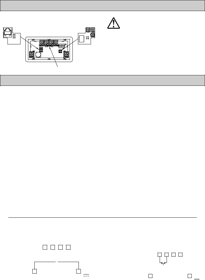
2.0 Setting the DIP Switches
To access the switches, remove the rear cover of the meter as described below. A bank of 4 switches is located in the upper right hand corner. After setting the switches, install any optional plug-in cards before replacing the rear cover (see next section).
Warning: Exposed line voltage exists on the circuit boards. Remove all power to the meter and load circuits before accessing inside of the meter.
REMOVE/REPLACE THE REAR COVER
To remove the rear cover, locate the cover locking tab below the 2nd and 3rd input terminals. To release the tab, insert a small, flat blade screwdriver between the tab and the plastic wall below the terminals. Inserting the screwdriver will provide enough pressure to release the tab locks. To replace the cover, align the cover with the input terminals and press down until the cover snaps into place.
SETTING THE INPUT DIP SWITCHES
The meter has four DIP switches for Input A and Input B that must be set before applying power. MAG SRCA LOA
Input.InputFreqInput.Input.
B
LOGIC: Input A trigger levels VIL = 1.25 V max.; VIH = 2.75 V min.; VMAX = 28 VDC
MAG: 200 mV peak input sensitivity; 100 mV hysteresis; maximum input voltage: ±40 V peak (28 Vrms); Must also have SRC switch ON. (Not recommended with counting applications.)
SWITCH 2
SNK.: Adds internal 7.8 KΩ pull-up resistor to +9 to
28 VDC, IMAX = 3.8 mA.
SRC.: Adds internal 3.9 KΩ pull-down resistor, 7.2 mA max. @ 28 VDC max.
Freq LO .
ON
|
|
|
|
|
|
|
|
|
|
|
|
|
|
|
|
|
|
|
|
|
|
|
|
|
|
|
|
|
|
|
|
|
|
|
|
|
|
|
|
|
|
|
|
|
|
|
|
|
1 |
|
|
2 |
|
|
3 |
|
4 |
|
|
|
.SNK Logic |
.Freq HI |
|
.Freq HI |
|||||||
 Factory Setting
SWITCHES 3 and 4
HI Frequency: Removes damping capacitor and allows max. frequency.
LO Frequency: Adds a damping capacitor for switch contact bounce. Limits input frequency to 50 Hz and input pulse widths to 10 msec.
3
3.0 Installing Plug-In Cards
The Plug-in cards are separately purchased option cards that perform specific functions. The cards plug into the main circuit board of the meter. After installing the cards, replace the rear cover before wiring the meter.
Comms or |
|
ON |
ECE |
|
|
1 |
2 |
3 |
4 |
Setpoint Card |
|
Programming |
|
|
|
|
|
|
|
|
|
|
|
Card |
|
|
|
|
|
|
Locking Tab |
|
|||
CAUTION: The Plug-in cards and main circuit board contain static sensitive components. Before handling the cards, discharge static charges from your body by touching a grounded bare metal object. Ideally, handle the cards at a static controlled clean workstation. Also, only handle the cards by the edges. Dirt, oil or other contaminants that may contact the cards can adversely affect circuit operation.
REMOVE/REPLACE THE REAR COVER
To remove the rear cover, locate the cover locking tab below the 2nd and 3rd input terminals. To release the tab, insert a small, flat blade screwdriver between the tab and the plastic wall below the terminals. Inserting the screwdriver will provide enough pressure to release the tab locks. To replace the cover, align the cover with the input terminals and press down until the cover snaps into place.
4.0 Wiring the Meter
WIRING OVERVIEW
Electrical connections are made via screw-clamp terminals located on the back of the meter. All conductors should conform to the meter’s voltage and current ratings. All cabling should conform to appropriate standards of good installation, local codes and regulations. It is recommended that the power supplied to the meter (DC or AC) be protected by a fuse or circuit breaker.
Strip the wire, leaving approximately 0.3" (7.5 mm) bare lead exposed (stranded wires should be tinned with solder.) Insert the lead under the correct screw-clamp terminal and tighten until the wire is secure. (Pull wire to verify tightness.) Each terminal can accept up to one #14 AWG (2.55 mm) wire, two #18 AWG (1.02 mm), or four #20 AWG (0.61 mm).
EMC INSTALLATION GUIDELINES
Although Red Lion Controls Products are designed with a high degree of immunity to Electromagnetic Interference (EMI), proper installation and wiring methods must be followed to ensure compatibility in each application. The type of the electrical noise, source or coupling method into a unit may be different for various installations. Cable length, routing, and shield termination are very important and can mean the difference between a successful or troublesome installation. Listed are some EMI guidelines for a successful installation in an industrial environment.
1.A unit should be mounted in a metal enclosure, which is properly connected to protective earth.
2.Use shielded cables for all Signal and Control inputs. The shield connection should be made as short as possible. The connection point for the shield depends somewhat upon the application. Listed below are the recommended methods of connecting the shield, in order of their effectiveness.
a.Connect the shield to earth ground (protective earth) at one end where the unit is mounted.
b.Connect the shield to earth ground at both ends of the cable, usually when the noise source frequency is over 1 MHz.
3.Never run Signal or Control cables in the same conduit or raceway with AC power lines, conductors, feeding motors, solenoids, SCR controls, and heaters, etc. The cables should be run through metal conduit that is properly grounded. This is especially useful in applications where cable runs are long
and portable two-way radios are used in close proximity or if the installation is near a commercial radio transmitter. Also, Signal or Control cables within an enclosure should be routed as far away as possible from contactors, control relays, transformers, and other noisy components.
4.Long cable runs are more susceptible to EMI pickup than short cable runs.
5.In extremely high EMI environments, the use of external EMI suppression devices such as Ferrite Suppression Cores for signal and control cables is effective. The following EMI suppression devices (or equivalent) are recommended:
Fair-Rite part number 0443167251 (RLC part number FCOR0000) Line Filters for input power cables:
Schaffner # FN2010-1/07 (Red Lion Controls # LFIL0000)
6.To protect relay contacts that control inductive loads and to minimize radiated and conducted noise (EMI), some type of contact protection network is normally installed across the load, the contacts or both. The most effective location is across the load.
a.Using a snubber, which is a resistor-capacitor (RC) network or metal oxide varistor (MOV) across an AC inductive load is very effective at reducing EMI and increasing relay contact life.
b.If a DC inductive load (such as a DC relay coil) is controlled by a transistor switch, care must be taken not to exceed the breakdown voltage of the transistor when the load is switched. One of the most effective ways is to place a diode across the inductive load. Most RLC products with solid state outputs have internal zener diode protection. However external diode protection at the load is always a good design practice to limit EMI. Although the use of a snubber or varistor could be used.
RLC part numbers: Snubber: SNUB0000
Varistor: ILS11500 or ILS23000
7.Care should be taken when connecting input and output devices to the instrument. When a separate input and output common is provided, they should not be mixed. Therefore a sensor common should NOT be connected to an output common. This would cause EMI on the sensitive input common, which could affect the instrument’s operation.
Visit RLC’s web site at http://www.redlion.net/emi for more information on EMI guidelines, Safety and CE issues as they relate to Red Lion Controls products.
4.1 POWER WIRING
DC Power
+9 to +28 VDC: +VDC |
USR |
INPB |
INPA |
COMMINP |
|||
Power Common: -VDC |
|
|
|
- 
 +
+
PWR COMMON |
+9-28 VDC |
4.2 USER INPUT WIRING
Sinking Logic
INP COMM |
Connect external switching device between the |
|||
USR |
}User Input terminal and Input Common. |
AINP |
||
|
COMMINP |
USR |
BINP |
|
The user input of the meter is internally pulled up to +9 to +28 V with 10 K resistance. The input is active when it is pulled low (<1 .0 V).
PWR COMMON |
+9-28 VDC |
4

4.3 INPUT WIRING
CAUTION: Power common (PWR COMMON) is NOT isolated from input common (INP COMM). In order to preserve the safety of the meter application, the power common must be suitably isolated from hazardous live earth referenced voltage; or input common must be at protective earth ground potential. If not, hazardous voltage may be present at the Signal or User Inputs and input common terminals. Appropriate considerations must then be given to the potential of the input common with respect to earth ground; and the common of the plug-in cards with respect to input common.
Magnetic Pickup |
|
|
AC Inputs From Tach Generators, Etc. |
Two Wire Proximity, Current Source |
|||||||||||||||
|
|
INP COMM |
|
|
Input A |
|
|
INP COMM |
|
INP B |
Input A |
|
|
|
INP COMM |
|
|
|
Input A |
|
|
USR |
INP B |
INP A |
|
|
USR |
INP A |
|
|
|
|
USR |
INP B |
INP A |
||||
ON |
|
|
|
|
|
ON |
|
|
|
|
|
ON |
|
|
|
|
|
|
|
|
|
* |
|
|
MAGNETIC PICKUP |
|
* |
* |
|
|
AC |
|
|
* |
* |
|
|
|
|
1 2 |
|
|
|
1 2 |
3 4 |
|
|
1 2 |
3 4 |
|
|
|
|
||||||
3 4 |
|
|
|
|
|
|
|
2.2 k Ω |
|
||||||||||
|
|
|
|
|
|
|
|
Resistor to Limit Current |
|
|
|
|
|
|
|
|
|||
|
|
|
|
|
|
|
|
to 2.5 mA MAX. |
|
|
|
|
|
|
|
|
|
||
|
PWR COMMON |
|
|
+9-28 VDC |
|
PWR COMMON |
|
|
+9-28 VDC |
|
|
PWR COMMON |
|
|
|
+9-28 VDC |
|||
Current Sinking Output |
Current Sourcing Output |
Interfacing With TTL |
|
||||||||||||||||
|
|
INP COMM |
|
|
Input A |
|
|
INP COMM |
|
|
Input A |
|
|
|
INP COMM |
|
|
|
Input A |
|
|
USR |
INP B |
INP A |
|
|
USR |
INP B |
INP A |
|
|
|
USR |
INP B |
INP A |
|
|||
ON |
|
|
|
|
|
ON |
|
|
|
|
|
ON |
|
|
|
|
|
|
|
|
|
|
|
|
|
|
|
|
|
|
|
|
|
|
|
|
|
|
|
|
|
* * |
|
|
NPN |
|
* |
* |
|
|
PNP |
|
|
* |
|
|
|
|
+5 V |
|
|
|
|
O.C. |
|
|
|
|
|
|
|
|
|
|
|||||
1 2 |
3 4 |
|
|
|
1 2 |
3 4 |
|
|
O.C. |
1 2 |
3 4 |
|
|
|
|
|
|||
|
|
|
|
|
|
|
|
|
|
COMMON |
|||||||||
|
|
|
|
|
|
|
|
|
|
|
|
|
|
|
|
|
|
|
|
|
|
PWR COMMON |
|
|
+9-28 VDC |
|
PWR COMMON |
|
|
+9-28 VDC |
|
PWR COMMON |
|
|
|
+9-28 VDC |
|||
Switch or Isolated Transistor; Current Sink |
Switch or Isolated Transistor; Current Source |
Current Sink Output; Quad/Direction |
|||||||||||||||||
|
|
INP COMM |
|
|
Input A |
|
|
INP COMM |
|
|
Input A |
|
|
|
INP COMM |
|
|
|
|
|
|
USR |
INP B |
INP A |
|
|
USR |
INP B |
INP A |
|
|
|
|
USR |
INP B |
INP A |
|||
ON |
|
|
|
|
|
ON |
|
|
|
|
|
ON |
|
|
|
|
|
|
|
|
|
|
|
|
|
* |
* |
|
|
|
|
|
|
|
|
|
|
||
|
* |
* |
|
|
|
|
|
|
|
|
|
|
|
|
|
|
|
||
|
|
|
|
1 2 |
3 |
4 |
|
|
|
|
|
|
|
|
|
|
|
||
1 2 |
3 |
4 |
|
|
|
|
|
|
1 2 |
3 |
4 |
|
|
|
|
||||
|
|
|
|
|
|
|
|
|
|
|
|
|
|||||||
|
PWR COMMON |
|
|
+9-28 VDC |
|
PWR COMMON |
|
|
+9-28 VDC |
|
|
PWR COMMON |
|
|
|
+9-28 VDC |
|||
|
|
|
|
|
|
|
|
|
|
|
|
|
|
||||||
Switch position is application dependent.
Shaded areas not recommended for counting applications.
4.4 SETPOINT (OUTPUT) WIRING
SINGLE SETPOINT RELAY PLUG-IN CARD
COM
N.O.
N.C.
DUAL SETPOINT N-FET OPEN DRAIN PLUG-IN CARD
COM
OSNK1
OSNK2
ELECTRICAL CONNECTIONS
COM N.O. N.C.
ELECTRICAL CONNECTIONS
OSNK 1(2)
(30 V MAX.)
COM
Note: Output Common is not isolated from DC Power Common. Load must be wired between OSNK terminal and V+ of the load supply.
4.5 SERIAL COMMUNICATION WIRING
SERIAL COMMUNICATIONS PLUG-IN CARD |
|
|
|
|
|
||||||
N/C B- |
A+ |
COMM |
N/C N/C |
N/C |
TX |
COMM |
COMM |
RX |
N/C |
||
6 |
5 |
4 |
3 |
2 |
1 |
6 |
5 |
4 |
3 |
2 |
1 |
|
|
RS485 |
|
|
|
|
RS232 |
|
|
||
|
RJ11 CONNECTOR PIN OUTS |
|
|||||||||
4.6 USB PROGRAMMING
USB PROGRAMING PLUG-IN CARD
5
 Loading...