

Page 1

service manual
r_02_0811
Page 2

SERVICE MANUAL
page 2
Rev. 02
08/11 – M.C.
Service Manual – 8901118900 – EN
All rights reserved
CONTENTS
1. FIVE BASIC RULES FOR INSTALLATION ............................................................................................................ 4
1.1. SUITABILITY OF THE ENVIRONMENT ........................................................................................................ 4
1.2. AIR INLET ...................................................................................................................................................... 4
1.3. SMOKE UNION .............................................................................................................................................. 4
1.4. FLUE PIPE ..................................................................................................................................................... 4
1.5. CHIMNEY ....................................................................................................................................................... 4
2. COMBUSTION CONTROL ...................................................................................................................................... 5
2.1. The RED recipes ............................................................................................................................................ 5
2.2. Combustion control ........................................................................................................................................ 5
2.3. Modify the recipe after the combustion control. ............................................................................................. 5
3. RED AIR AND MULTIAIR STOVES ........................................................................................................................ 6
3.1. Interpretation of installation ............................................................................................................................ 6
3.2. Recipe selection for AIR and MULTIAIR products ......................................................................................... 8
3.3. Modifying the speed of the smoke blower fan on AIR and MULTIAIR products ............................................ 8
3.4. RED AIR and MULTIAIR stove settings ......................................................................................................... 9
3.4.1. External room thermostat ........................................................................................................................ 9
3.4.2. ECO-STOP mode ................................................................................................................................... 9
3.5. Signals during operation............................................................................................................................... 10
4. RED HYDRO STOVES AND THE COMPACT 24 BOILER .................................................................................. 11
4.1. Adjusting the recipe in HYDRO stoves and in the COMPACT24 ................................................................ 11
4.2. First ignition: what to check .......................................................................................................................... 11
4.2.1. Regular operation of HYDRO stoves and COMPACT24 ...................................................................... 13
4.3. RED HYDRO and COMPACT24 stove settings .......................................................................................... 13
4.3.1. External room thermostat ...................................................................................................................... 13
4.3.2. ECO-STOP mode ................................................................................................................................. 13
4.3.3. Water temperature differential .............................................................................................................. 13
4.4. Information about the operation of the appliance ......................................................................................... 14
4.5. Shut down, recipe adjustment and bypassing the start-up phase ............................................................... 14
5. RED PELLET BOILERS: PRACTIKA 28-33 – VARIOMATIC 33 ......................................................................... 15
5.1. Adjusting the recipe in the boilers ................................................................................................................ 15
5.2. The adjustment of the smoke blower (optional on Practika, standard on Variomatic) ................................. 15
5.3. First ignition: what to check .......................................................................................................................... 16
5.3.1. External room thermostat ...................................................................................................................... 18
5.3.2. ECO-STOP mode ................................................................................................................................. 18
5.3.3. Water temperature differential .............................................................................................................. 19
5.3.4. AUX contact .......................................................................................................................................... 19
5.3.5. Testing individual components .............................................................................................................. 20
5.3.6. Regular operation.................................................................................................................................. 20
5.4. Information about the operation of the appliance ......................................................................................... 20
5.5. Special settings on boilers – TECHNICAL MENU ....................................................................................... 21
6. TECHNICAL PARAMETERS. ................................................................................................................................ 22
6.1. How to access technical parameters ........................................................................................................... 22
6.2. Stove parameters ......................................................................................................................................... 23
6.3. Boiler parameters ......................................................................................................................................... 27
7. FAULT SIGNALLING ............................................................................................................................................. 30
7.1. Alarm signal and exiting alarm conditions. ................................................................................................... 30
7.2. Control panels and list of alarms .................................................................................................................. 30
7.2.1. RED AIR and MULTIAIR stove alarms ................................................................................................. 30
7.2.2. RED COMPACT 24 boiler alarms ......................................................................................................... 31
7.2.3. RED PRACTIKA 25-33 and VARIOMATIC 33 boiler alarms ................................................................ 32
8. FAULT SOLUTIONS .............................................................................................................................................. 33
Page 3

SERVICE MANUAL
page 3
Rev. 02
08/11 – M.C.
Service Manual – 8901118900 – EN
All rights reserved
8.1. LED -2 / NO ACC / A01= Start-up failed ...................................................................................................... 33
8.2. LED -1 / ALAR NO FIRE / A02 = Abnormal fire extinguishing ..................................................................... 35
8.3. LED 0 / ALAR SIC FAIL / A03= Pellet tank safety thermostat ..................................................................... 37
8.4. LED 0 / DEP FAIL / A05 ............................................................................................................................... 38
8.5. LED +1 / ALAR FAN FAIL / A08= Smoke blower fan .................................................................................. 39
8.6. LED +2 / ALAR HOT TEMP / ALAR SOND FUMI / A04 .............................................................................. 41
8.7. A10 ............................................................................................................................................................... 41
8.8. A11 ............................................................................................................................................................... 41
8.9. A13 ............................................................................................................................................................... 41
9. SCHEDULED MAINTENANCE. ............................................................................................................................. 43
9.1. RED AIR and MULTIAIR pellet stoves ......................................................................................................... 43
9.2. RED HYDRO pellet stoves ........................................................................................................................... 43
9.3. COMPACT 24 boiler ..................................................................................................................................... 44
9.4. PRACTIKA 28-33 boiler ............................................................................................................................... 44
9.5. VARIOMATIC 33 boiler ................................................................................................................................ 45
9.6. Why perform scheduled maintenance? ........................................................................................................ 45
10. ELECTRICAL CONNECTIONS ........................................................................................................................... 46
10.1. RED AIR and MULTIAIR pellet stoves ..................................................................................................... 46
10.2. RED HYDRO pellet stoves ....................................................................................................................... 47
10.2.1. RED HYDRO stoves without a DHW kit ............................................................................................ 47
10.2.2. RED HYDRO stoves without a DHW kit for high efficiency pumps (if included) ............................... 48
10.3. RED PRACTIKA 28-33 boiler ................................................................................................................... 49
10.4. RED VARIOMATIC 33 boiler .................................................................................................................... 51
11. RED PRODUCTS AND THEIR ELECTRONIC AND MECHANICAL COMPONENTS....................................... 52
Page 4

SERVICE MANUAL
page 4
Rev. 02
08/11 – M.C.
Service Manual – 8901118900 – EN
All rights reserved
1. FIVE BASIC RULES FOR INSTALLATION
1.1.
SUITABILITY OF
THE
ENVIRONMENT
1.2.
AIR INLET
1.3.
SMOKE UNION
1.4.
FLUE PIPE
1.5.
CHIMNEY
An open fireplace
consumes ~45m3 of
air per kg of fuel.
The installation
environment must
ensure as much air
as the appliance can
consume.
Refer to the
manufacturer's
technical data
concerning fuel
consumption to
determine the
minimum size of the
installation
environment.
Adhere to the safety
distances specified
by the manufacturer
for walls and/ or
flammable surfaces.
Maintain the safety
distances from
furniture and other
furnishing items that
may be damaged by
the heat.
Insulate smoke
ducts positioned
close to flammable
materials.
Installation is not
permitted in rooms
already containing
a type-A or
ventilation hood
appliance.
This is obligatory
to ensure a correct
flow of air to
reintegrate the
oxygen consumed
by the appliance in
the installation
environment.
It is important to
create an air inlet
leading directly to
the external
environment.
Size the air inlet
correctly, according
to the dimensions
specified by the
manufacturer.
The air inlet
performs two
functions:
It provides sufficient
air intake to allow
the product to
operate correctly.
It provides air in the
environment to
compensate the air
consumed by
combustion.
The smoke
connection is the
piece of pipework
that connects the
flue pipe to the
appliance. This
connection must
adhere to
fundamental safety
and heat resistance
requirements.
The use of flexible
pipes is not
permitted.
Therefore the
connection can be
constructed using
only rigid pipes
made from:
stainless steel or
aluminised steel.
Forced outlet
products must be
connected using
airtight pipes fitted
with suitable sealing.
When connecting
closed fireplaces
only use changes of
direction with a
maximum inclination
of 45°.
Use a maximum of
three 90° bends for
pellet stoves.
The connection
must NEVER be
smaller in size at
the smoke outlet of
the appliance.
The flue pipe is a
vital element for the
discharge of smoke
and should
therefore:
Be waterproof and
thermally
insulated.
Be made of suitable
heat-proof materials
that are resistant to
the effects of
combustion
products and any
possible
condensation.
Have a vertical
arrangement with
deviations from the
axis of no more than
45° and without
kinks.
Must discharge the
smoke at the
highest point of
the home.
Comply with the
requisites specified
in the technical
table, such as the
internal crosssection of the
chimney and the
height.
Have an internal
section which is
preferably circular.
Be cleaned if preexisting and has
previously operated.
Wall outlets are
forbidden for pellet
stoves.
The chimney is the
end part of the flue
pipe. Correct
draught for the flue
pipe depends on the
chimney.
The chimney must:
Have an inner
section equal to that
of the flue pipe.
Have a outlet
section of at least
double that of the
inner section of the
flue pipe.
Be built in such a
way as to prevent
rain, snow and any
foreign bodies from
penetrating the flue
pipe.
Be positioned so as
to ensure adequate
dispersion of smoke
and, in all cases,
outside the reflux
area in which backpressures are likely
to form.
Page 5
SERVICE MANUAL
page 5
Rev. 02
08/11 – M.C.
Service Manual – 8901118900 – EN
All rights reserved
2. Combustion control
2.1. The RED recipes
RECIPES are preset programmes stored on the appliance mother board. These recipes contain a series of
parameters concerning the operation of the stove in all its modes.
Recipes contain, first and foremost, the values relating to the start-up and shutdown times of the geared motor and
the number of revolutions at which the smoke blower fan needs to operate at the various heat outputs.
The concept used to create recipes involves varying the intake of fuel that falls into the brazier, depending on the
quality of the flame.
2.2. Combustion control
To be certain that the correct recipe has been created, switch on the appliance and check the combustion when
the flame is stable and regular.
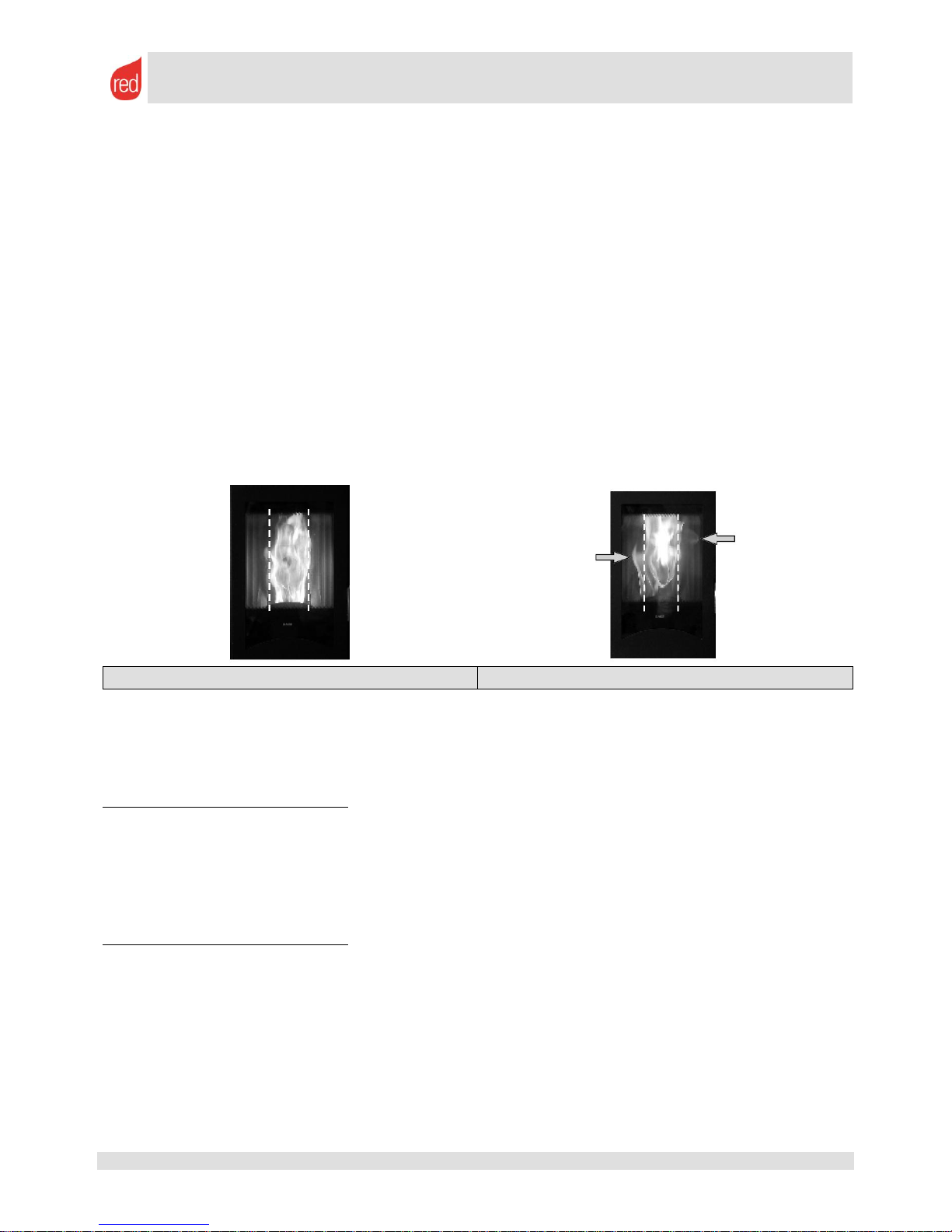
The flame must be yellow on the sides and white in the centre. It should not be excessively slow nor too
oxygenated. The top of the flame must be aspirated towards the top part of the combustion chamber and must
always remain within the outline of the brazier and not overflow to the sides.
The bottom must almost always be visible, given that the whole of the pellets that fall during a cycle of the geared
motor burn fully before the final load cycle.
The flame must also "pulse" (move up and down) as pellets are burnt immediately when loaded.
CORRECT FLAME
IRREGULAR FLAME
2.3. Modify the recipe after the combustion control.
A flame that is too oxygenated is low, very white and "nervous" and the embers of the pellet tend to overflow the
brazier. The most obvious fault is a flame that is always low and a tendency of the fire to go out, particularly at low
outputs.
The variations to make are as follows:
Increase the quantity of pellets falling into the brazier (by percentage)
A flame that is not very oxygenated is orange, weak and tends to produce puffs of smoke. The glass and the
ALUTEC® (white interior refractory material) get dirty and blacken quickly.
The most obvious fault is an accumulation of pellets inside the brazier. The faster the accumulation time, the
greater the variations that must be made to the recipe.
The variations to make are as follows:
Decrease the quantity of pellets falling into the brazier (by percentage)
POSSIBLE OTHER SOLUTIONS TO THE CALIBRATION PROBLEM:
If the problem persists carefully check that the seals on the door and ash drawer are working correctly, that all of
the cleaning caps on the combustion chamber are closed and that there are no obstructions in the flue pipe.
Remember that the quality of the pellets is fundamental for correct combustion and is a basic rule for the
combustion described above.
Page 6

SERVICE MANUAL
page 6
Rev. 02
08/11 – M.C.
Service Manual – 8901118900 – EN
All rights reserved
3. RED AIR and MULTIAIR stoves
3.1. Interpretation of installation
One of the first actions to carry out to select the correct combustion parameters for our stove is to identify and
understand whether the installation that you are carrying out (or find yourself dealing with) presents any difficulties
with regard to evacuating exhaust smoke. Therefore, we have divided the installation types into three large macro
categories:
ACTIVE, meaning that the smoke connection is very short, free or almost free of bends and allows almost
direct connection in an "active" flue pipe; in other words, a flue pipe with a minimum natural draught of 0.10
mbar when warm.
These types of installation do not usually require additional adjustments as the basic recipe that
the stove leaves the manufacturer with has been designed for installation using a flue pipe with a
minimum natural draught of 0.10 mbar, as indicated in the use and installation manual of the
product.
PASSIVE, meaning that the smoke connection is more winding as it has bends and/ or a few metres of
pipework. If you are carrying out (or find yourself dealing with) an installation of this type, remember that
there are maximum parameters to adhere to. The stove is not guaranteed to operate if these parameters
are exceeded. For this type of installation:
o Never include more that three 90° bends.
o Never include more that three metres of Ø 80 mm horizontal pipework. This pipework must have a
minimum gradient of 3-5%.
o Never use counter-sloping pipes (pointing downwards).
o Never create a connection with more that six metres of Ø 80 mm pipework.
o Always install an inspection "T" at the outlet of the appliance (avoid 90° and 45° bends).
“WALL” installations (forbidden in Italy, Germany, Austria and Switzerland according to current laws but
permitted in some European countries) carry a high degree of risk. If you decide to use this type of
installation we recommend that you adhere to the following:
o Protect the outlet of the pipework from the wind as effectively as possible.
o ALWAYS use a windproof chimney (preferably one of high quality, not restricting the installation
to a simple windproof cap for boilers).
o Do not use 90° or "T" bends instead of windproof chimneys. Usually these stratagems cause a
deterioration in operation.
o Always construct the shortest possible connection.
o Avoid using sections of non-insulated, external pipework
o Avoid vertical rises in pipework close to walls as the walls can become dirty.
o Smoke discharge below balconies, terraces and eaves should be strictly avoided. You may think
that installing the discharge in these areas better protects the outlet from the wind but, in fact, the
opposite is true. Wind nestles in these areas of the home and makes it difficult for smoke to exit.
There is also a high risk of the building become very dirty.
N.B. The manufacturer bears no responsibility for malfunctions or damage to property and persons. An
installation carried out in this manner may also invalidate the guarantee.
These types of installation normally require additional adjustments to modify either the fuel intake
or the combustion air intake. To carry out these modifications follow the general concepts of
observing the flame explained in the previous paragraph and the instructions given in the next
chapter regarding the modification of pellet dosing and the speed of the smoke blower fan.
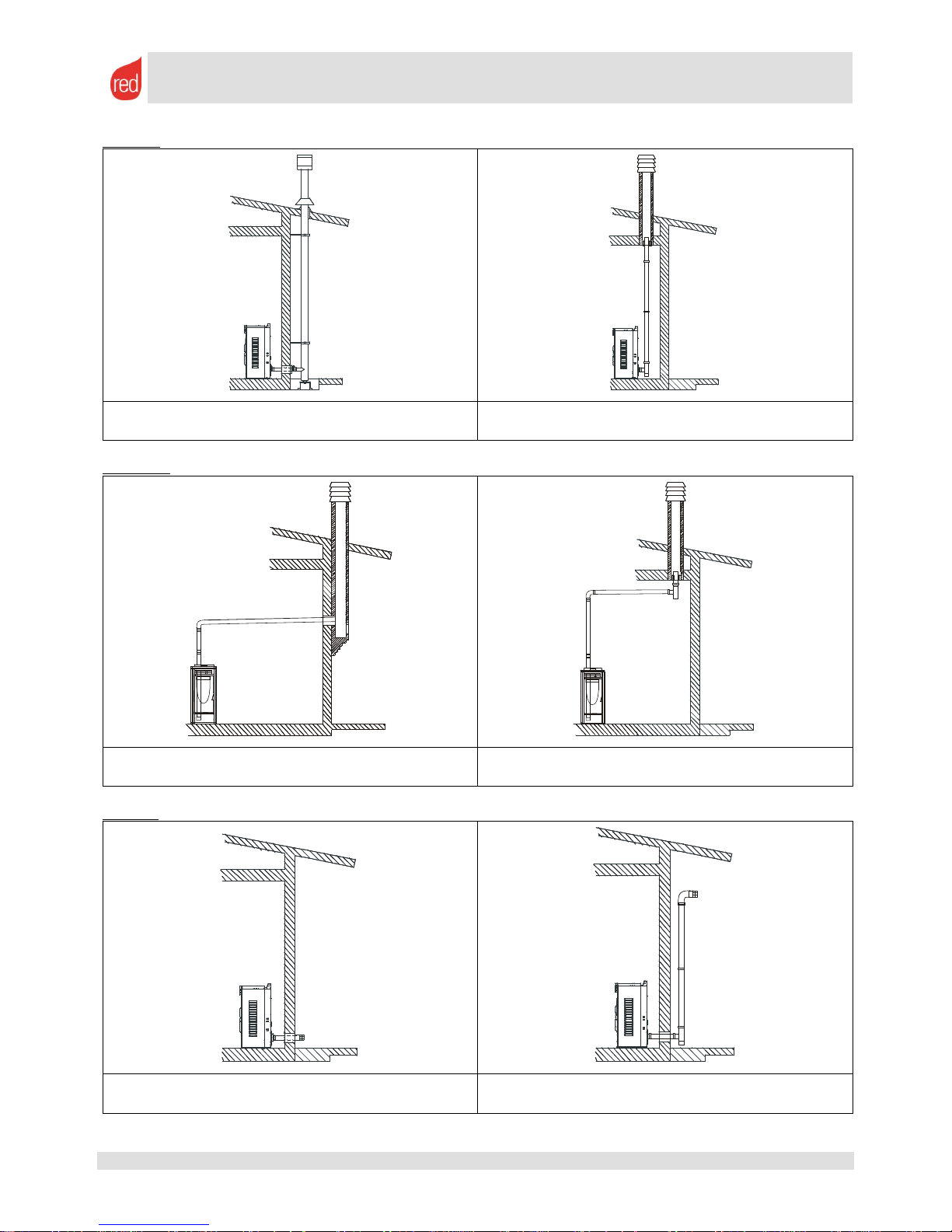
To further help you to identify the different types of installation, some examples are given below:
Page 7
SERVICE MANUAL
page 7
Rev. 02
08/11 – M.C.
Service Manual – 8901118900 – EN
All rights reserved
ACTIVE
50-70 cm connection to the insulated flue pipe without
bends.
Connection to an existing flue pipe with a minimum
draught of 10 Pascal (Pa) when warm.
PASSIVE
Very long connections to the flue pipe
Connections with various bends and a few metres of
pipework.
"WALL"
Direct outlets to walls (not recommended and not
permitted)
Wall outlets with bends and a few metres of pipework
+ chimney (not recommended and not permitted)
Page 8
SERVICE MANUAL
page 8
Rev. 02
08/11 – M.C.
Service Manual – 8901118900 – EN
All rights reserved
3.2. Recipe selection for AIR and MULTIAIR products
The recipe, and therefore the intake of fuel into the brazier, is modified as follows:
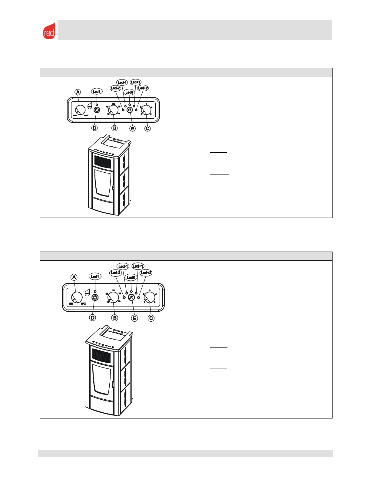
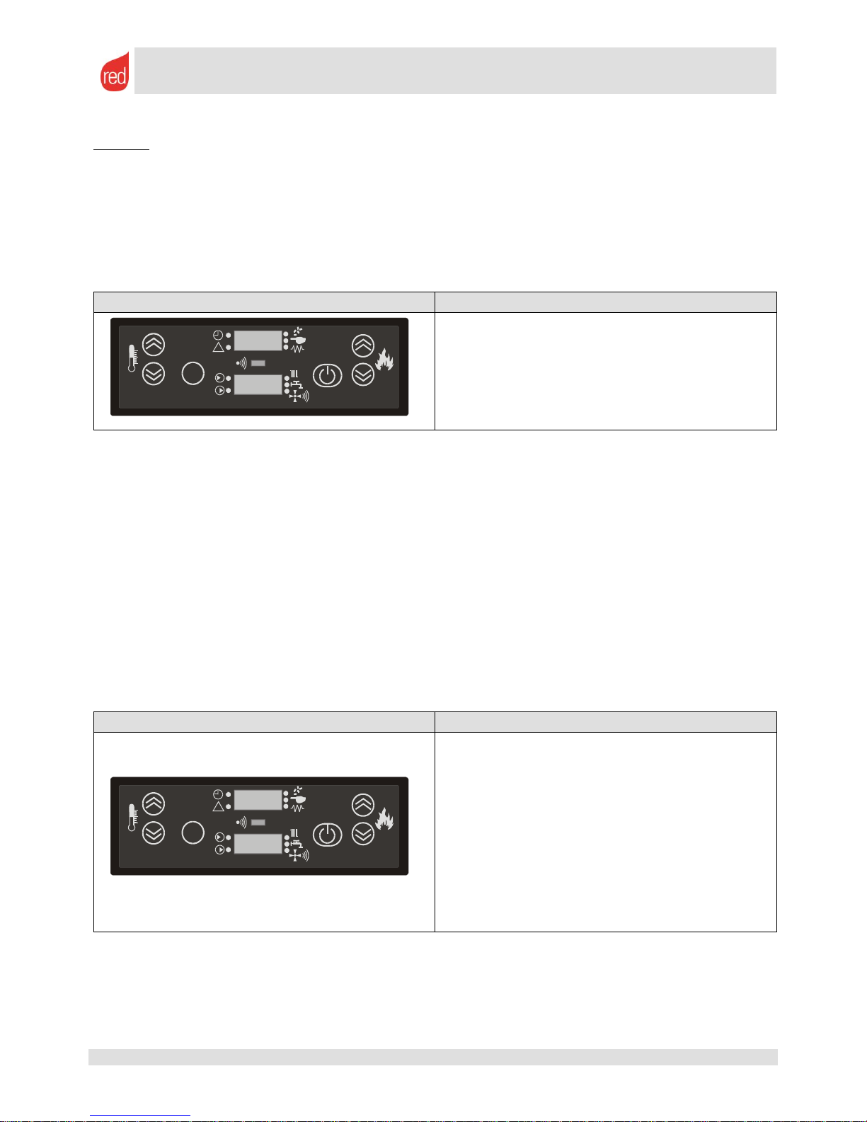
TYPE OF PANEL
INSTRUCTIONS
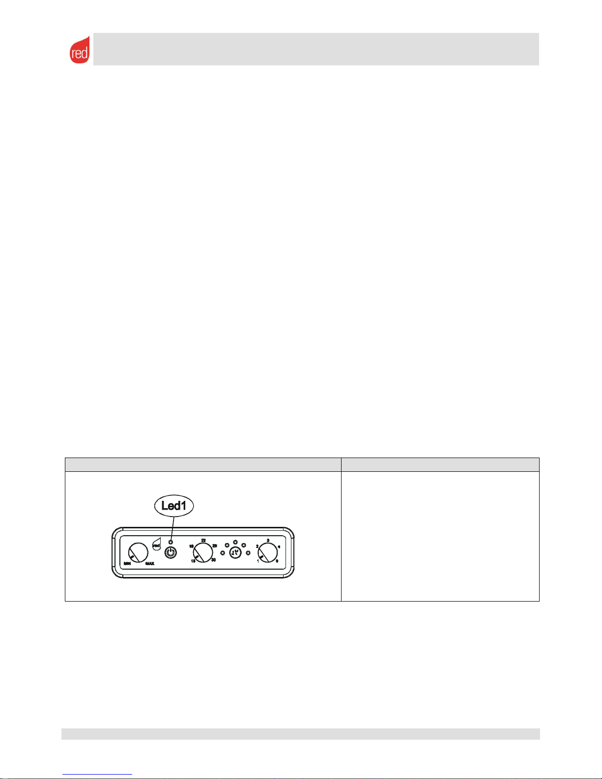
1. Press button E repeatedly until the led
corresponding to the variation that you wish to
make lights up. Take into account that:
LED -2 = -20% pellet
LED -1 = -10% pellet
LED 0 = no variation from the standard.
LED +1 = +10% pellet
LED +2 = +20% pellet
2. No confirmation is required as the led
corresponding to the selection made will always
remain lit during operation.
3.3. Modifying the speed of the smoke blower fan on AIR and MULTIAIR products
In addition to medicating the recipe, you can increase or reduce the power of the smoke blower in percentages (in
the same way as for pellet loading) to modify or improve combustion. This modification is carried out as follows:
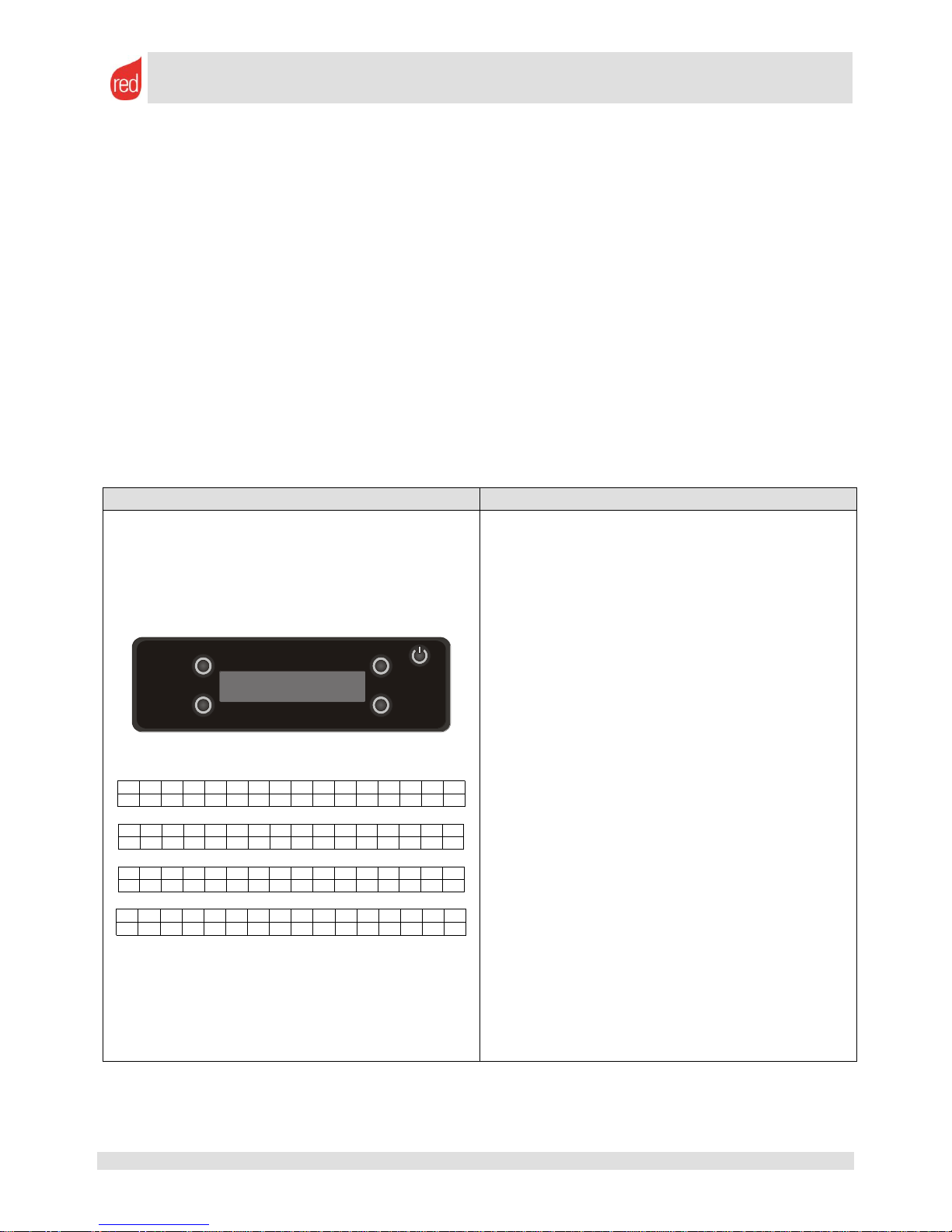
TYPE OF PANEL
INSTRUCTIONS
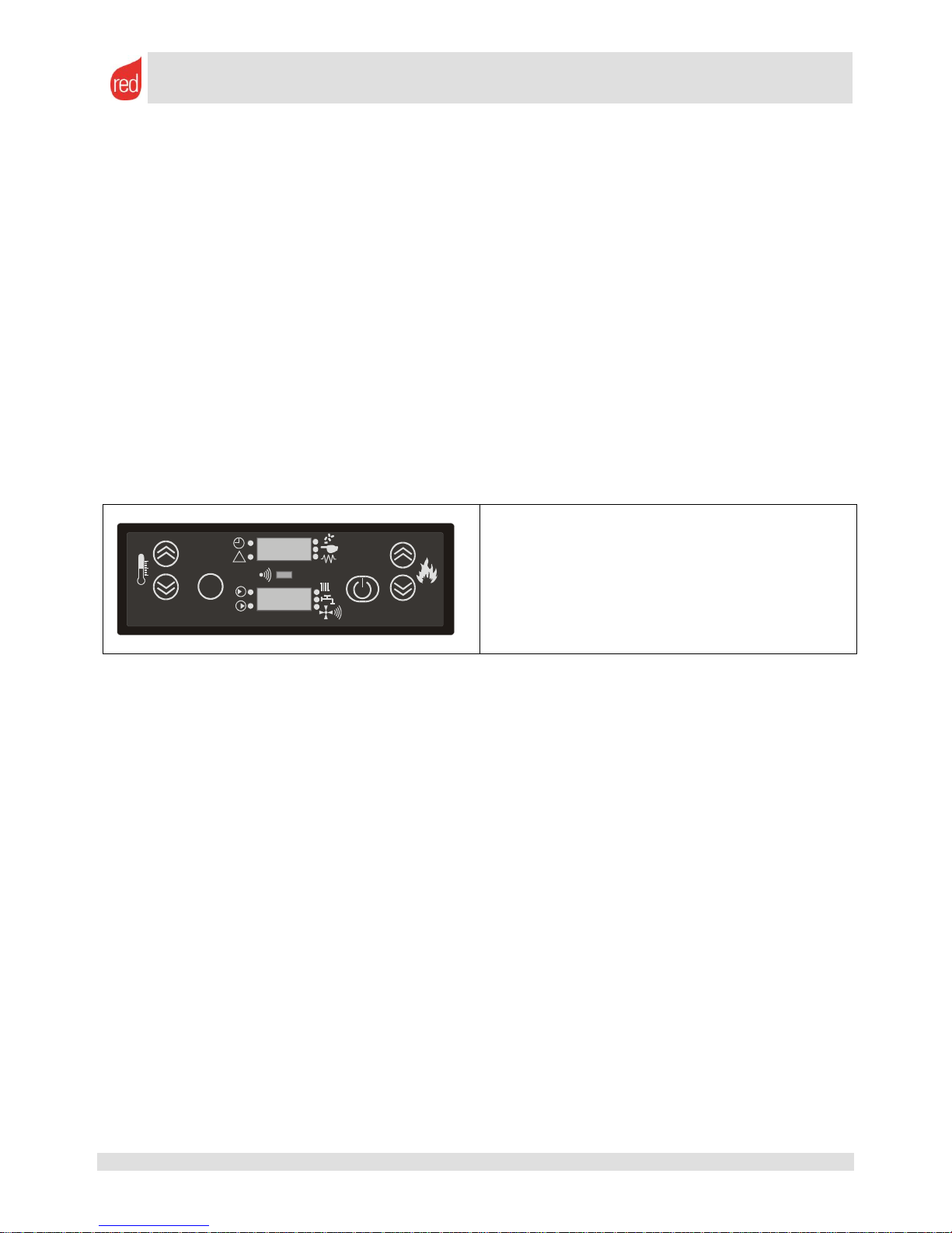
1. Press buttons E and D at the same time.
2. LED 0 will begin to flash. This means that the
speed of the smoke blower fan (rather than the
pellet dosage) can now be modified. If the pellets
are modified the led remains lit with a fixed light (not
flashing).
3. Press button E until the led corresponding to the
variation that you wish to make lights up. Take into
account that:
LED -2 = -20% rpm
LED -1 = -10% rpm
LED 0 = no variation from the standard.
LED +1 = +10% rpm
LED +2 = +20% rpm
4. No confirmation is required as the led corresponds
to the selection made. Simply wait 5 seconds for the
display to return to the initial status.
Page 9
SERVICE MANUAL
page 9
Rev. 02
08/11 – M.C.
Service Manual – 8901118900 – EN
All rights reserved
3.4. RED AIR and MULTIAIR stove settings
3.4.1. External room thermostat
An external room thermostat can be connected to all appliances. To do this, the two cables from the external
thermostat must be connected directly to the motherboard.
As the internal thermostat, (controlled by potentiometer B) cannot be deactivated, it must be set to the minimum,
that is; turned fully to the left (as shown in the figure). In this way, the external thermostat will take control of the
stove as the internal thermostat is adjusted to a very low temperature and therefore always satisfied (internal
electronic contact always closed).
All types of ON-OFF timed or room thermostat are compatible with RED appliances.
Remember that using a simple ON-OFF thermostat will allow you to reduce the operating power of the stove to a
minimum when the desired room temperature has been reached.
If, on the other hand, you wish the appliance to switch off when the temperature is reached you MUST activate
the ECO-STOP function, as described in the instructions given in the next paragraph.
CONTROL PANEL
INSTRUCTIONS
1. Connect the two cables to the board as shown in
the figure
2. Rotate potentiometer B of the internal thermostat
fully to the left, in other words to the minimum
possible temperature.
3. Adjust the desired temperature on the external
thermostat.
If you wish the stove to switch off when it reaches the
temperature activate the ECO-STOP function
3.4.2. ECO-STOP mode
This function can be considered an "advanced automatic" mode that prompts the appliance to switch off when
the temperature is reached rather than simply reducing the minimum power (ECO). We recommend that you
DO NOT use the ECO-STOP function in rooms with minimal insulation or if cooling in the installation room is
very sudden. If used in these conditions the appliance will be forced to switch on and off frequently, consequently
degrading the igniter and/ or causing failed ignition as the ignition is carried out in a dirty combustion chamber and/
or brazier with obstructed holes.
TYPE OF PANEL
INSTRUCTIONS
ECO-STOP activation
1. Press ON/OFF button D five times in a row
within a 6 second time period
2. The board responds by sounding a long signal to
confirm (3 seconds).
To deactive ECO-STOP: as with activation, press the
ON/OFF button briefly five times in a row within a 6
second time period. The board responds by sounding a
long signal to confirm (4 seconds).
Page 10
SERVICE MANUAL
page 10
Rev. 02
08/11 – M.C.
Service Manual – 8901118900 – EN
All rights reserved
Other instructions for a full understanding of the ECO-STOP function and how the panel signals the various
behaviours:
When the temperature is satisfied (temperature sensor on the edge of the stove satisfied or external
thermostat, if present, satisfied (open contact)) the stove enters the Eco-Stop counting phase. This phase
prompts the gradual passage from power 5 to power 1. The decrease in temperature lasts for one minute
for each power to prevent the flame from descending too suddenly.
When the first power level has been reached the appliance begins a countdown of 20 minutes. At the end
of the countdown, if the temperature is still satisfied the appliance will begin to shut down. On the other
hand, if during these 20 minutes the temperature once again becomes unsatisfactory for more than 10
seconds (to exclude a momentary indication), the count immediately zeros. If the temperature in the room
has decreased the stove will return to maximum power. If the temperature has not decreased the stove
will remain on minimum power and will restart the countdown to attempt a new shut down in ECO-STOP
20 minutes later.
When shutting down via ECO-STOP, LED1 will flash every 2 seconds with an alternating orange and
green led
When ECO-STOP puts the stove into stand-by mode LED1 will flash every 2 seconds with an alternating
orange and green led
ECO-STOP switches the stove back on when both of the following conditions are present:
At least 5 minutes have elapsed since the switch off process began;
The room temperature is at least 2 °C lower than the set temperature
(e.g.: if set to 20 °C, the stove restarts when the temperature drops below 18 °C)
If operating with an external thermostat the contact of this thermostat will control the restart.
N.B.: to exclude a momentary indication, the aforementioned conditions must remain present for 10
consecutive seconds.
When ECO-STOP switches the stove back on LED1 will flash green (as with normal ignition)
If the stove is switched off manually using the ON/OFF button with the ECO-STOP function active, ECO-
STOP will still be active the next time the stove is started up
If there is a black-out while the stove is switched on or in stand-by mode with ECO-STOP active, when the
stove restarts ECO-STOP will switch it off and then on again (if the temperature is not satisfactory, with a
delay of 120 seconds)
3.5. Signals during operation.
TYPE OF PANEL
LED 1
Off: The stove is waiting to start up
Flashing green: Start up
Fixed green: Stove on at full power
Flashing orange: Shut down
Flashing red: Alarm in progress
Fixed red: Stove switched off after alarm
If the stove switches off after a mains power failure led 1 continues to flash orange even after cooling.
Page 11
SERVICE MANUAL
page 11
Rev. 02
08/11 – M.C.
Service Manual – 8901118900 – EN
All rights reserved
4. RED HYDRO stoves and the COMPACT 24 boiler
Unlike pellet stoves designed to heat only air, Hydro pellet stoves and boilers have all the complexities of
combining the appliance to an existing hydraulic system.
Therefore, it is essential that these appliances are correctly installed by a specialised heating engineer who
can also calculate the heat requirement of the system.
These appliances are fitted with all the necessary operating and safety devices to apply it to a CLOSED VESSEL
system and, therefore, can only operate when the pressure of the system is between 0.5 and 2.5 bar. The
recommended operating pressure is 1.0 bar when cold and/ or 1.5 bar when warm.
4.1. Adjusting the recipe in HYDRO stoves and in the COMPACT24
Unlike other air stoves, the HYDRO stove and boilers do not present any significant difficulties with regard to
selecting the recipe as the power of the smoke blower fan and the high fuel load make adjusting the combustion
much less delicate.
To set the recipe just follow the simple instructions below. However, you should do this only if there are fuel
accumulation faults or the flame is too low and weak, as explained in chapter 2.
With regard to the COMPACT 24 boiler, the flame in the combustion chamber cannot be fully seen. There is only a
small viewing window on the fire door to allow you to check whether there is a flame. Boilers, even more than
stoves, require very little adjustment. Therefore, adjustments must only be made if the fuel is not compliant or the
boiler output is low due to low/ excessive fuel intake.
Take great care not to overload the brazier. This would undoubtedly produce a better output but would
also cause continuous overheating of the structure and therefore shorten the life of the product.
With the stove is switched off, press buttons
and at the same time
Select the recipe using buttons or
Confirm the selection using button , keeping it
held down until the word OFF appears on the
display
The fuel load is adjusted by percentage. In other words, you can modify the pellet chute by percentage compared
to the basic standard adjustment.
The possible adjustments are:
-3 = -30% pellet
-2 = -20% pellet
-1 = -10% pellet
0 = standard adjustment by the manufacturer
+1 = + 5%
+2 = +10%
+3 = +15%
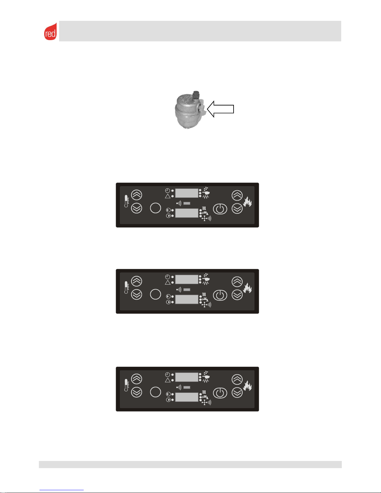
4.2. First ignition: what to check
Always carry out a preventative check of the number of radiators and the system's potential absorption. Also
check the flow and return pipes, both in terms of the diameter and the insulation.
The stove MUST be connected to the hydraulic system using flexible pipes and inserting cut-off cocks to
isolate the appliance should it require maintenance.
Load the system with cold water using the associated filler cock located on the rear of the system or via
another filler cock on the system. Bring the pressure to 1.5 bar.
The pressure of the system must be checked using an external pressure gauge that must be installed near to
the stove (recommended), using the gauge supplied (Compact 24) or a gauge already fitted on the system, for
example the gauge already fitted on the gas boiler (if present)
SET
TURBO
1
2
6 4
3
5
!
Page 12
SERVICE MANUAL
page 12
Rev. 02
08/11 – M.C.
Service Manual – 8901118900 – EN
All rights reserved
Check that there are no leaks from the hydraulic connections of the stove and the system. Tighten the
connections if necessary. The internal pipes are tightened dry and tested with compressed air at 4 bar.
However, an additional check is essential when the system is filled with water and pressurised.
Vent the air from the system of radiators via the associated valves.
Vent the stove via the relief valve underneath the ceramic/ steel top. If necessary, reintegrate the system to
bring the pressure to the recommended levels (1.5 bar).
Check that the room sensor (located on the rear of the system) is not touching any hot parts and is in a
suspended position to detect the temperature of the room.
Adjust the correct recipe according to procedure.
Check the calibration of the room temperature by pressing the SET button .
Use buttons and to bring the temperature to the desired level. This must be a higher temperature than
that in the room to power the appliance.
Check the calibration of the water temperature by pressing the SET button . Use buttons and to bring
the temperature to the desired level. This temperature must NEVER BE LOWER THAN 55 °C. Below this
temperature significant production and condensation problems can occur. The recommended temperature is
65 °C.
Start up the stove and wait for the water in the boiler to reach 50 °C. At this temperature the circulation pump
(water pump) begins to operate and the hot water begins to circulate in the system. When cold water returns to
the boiler the water inside the boiler itself will rapidly drop in temperature and the circulation pump will stop.
This is perfectly normal and can last 20 to 40 minutes, depending on the size of the system. When all the
water inside the system reaches a temperature above 52 °C, the circulation pump will remain permanently
active.
You can adjust the temperature at which the pump intervenes by entering the technical parameters (see
chap. 6. ) and, more precisely, by modifying parameter PR 28.
Use buttons and to modify the start up/ shut down temperature of the circulation pump. We recommend
that you do not excessively lower the temperature (MIN 40 °C) or excessively exceed the threshold (MAX
55 °C).
SET
TURBO
1
2
6 4
3
5
!
21°C
52°C
SET
TURBO
1
2
6 4
3
5
!
H2O
65°C
SET
TURBO
1
2
6 4
3
5
!
AMB
25°C
Page 13
SERVICE MANUAL
page 13
Rev. 02
08/11 – M.C.
Service Manual – 8901118900 – EN
All rights reserved
4.2.1. Regular operation of HYDRO stoves and COMPACT24
Once the appliance reaches regular operation it autonomously selects the operating power according to the
difference between the required and desired room and water temperatures.
THE APPLIANCE OPERATES ONLY IN AUTOMATIC MODE (MANUAL mode does not exist)
The flame begins to decrease its operating power 5 °C before reaching the temperature of the water in the boiler.
This prevents the stove from exceeding the desired water temperature due to the thermal flywheel. The stove goes
into ECO mode (minimum power) when one or both of the temperatures requested (water and air) have been
satisfied.
4.3. RED HYDRO and COMPACT24 stove settings
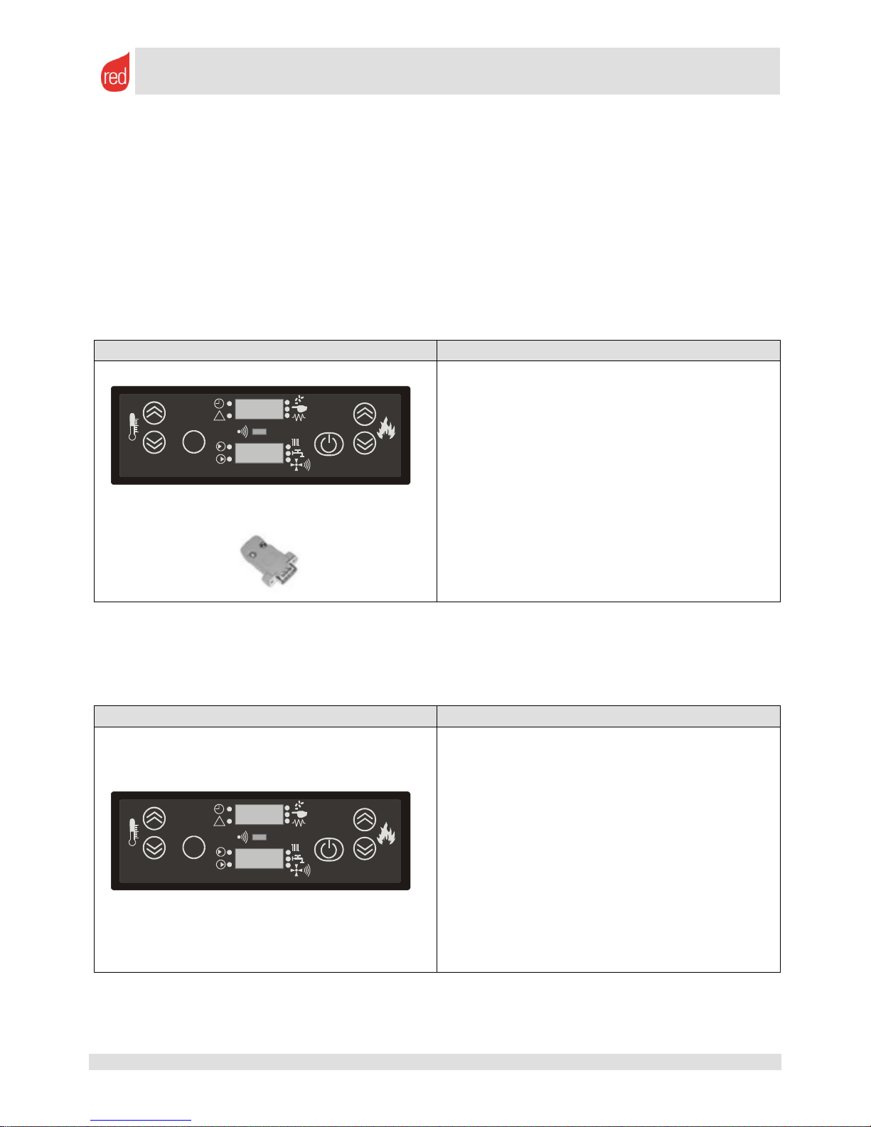
4.3.1. External room thermostat
An external room thermostat can be connected to all appliances. To do this, connect the thermostat to the serial
port using the associated connector supplied (photo to the side). The method for operating this option is shown
below.
CONTROL PANEL
INSTRUCTIONS
1. Press buttons and at the same time to
access UT01
2. Press button several times until you reach
UT16
3. Press and hold the button
4. While pressing this key, press button several
times at the same time until you reach UT20
5. Set the internal thermostat to OFF using button
or
6. Confirm the selection using button
4.3.2. ECO-STOP mode
This function can be considered an "advanced automatic" mode that prompts the appliance to switch off when
the temperature is reached rather than simply reducing the minimum power (ECO). We recommend that you
DO NOT use the ECO-STOP function in rooms with minimal insulation or if cooling in the installation room is
very sudden. If used in these conditions the appliance will be forced to switch on and off frequently.
CONTROL PANEL
INSTRUCTIONS
1. Press buttons and at the same time to
access UT01
2. Press button several times until you reach
UT16
3. Press and hold the button
4. While pressing this key, press button at the
same time until you reach UT19
5. Set the internal ECO-STOP to ON using keys
or and select the number of minutes after which
you want the ECOSTOP to intervene.
6. Confirm the selection using button
4.3.3. Water temperature differential
You can increase or decrease the temperature differential to prevent the temperature of the water in the boiler from
exceeding a value determined and set by the user. This differential is set in UT18 in sets of 10 °C. To access
SET
TURBO
1
2
6 4
3
5
!
SET
TURBO
1
2
6 4
3
5
!
Page 14
SERVICE MANUAL
page 14
Rev. 02
08/11 – M.C.
Service Manual – 8901118900 – EN
All rights reserved
UT18, follow the same procedure used to access UT19.This interval forces the stove to decrease the operating
power if the water reaches the set temperature plus 10 °C.
Example: SET WATER TEMPERATURE = 65 °C
TEMPERATURE DIFFERENTIAL = 10 °C
At a temperature of 75 °C the stove is forced to go to minimum power to prevent the water from
overheating and boiling.
4.4. Information about the operation of the appliance
You can retrieve information about the operation of the appliance while is it switched on or during some specific
operating phases.
This information is often fundamental to solving problems or correctly diagnosing operation and faults.
CONTROL PANEL
INSTRUCTIONS
Pressing and holding down button will provide two
pieces of information:
The number of revolutions of the smoke blower
detected by the encoder (E.g.: 1840)
The instant temperature of the smoke sensor (E.g.:
103°)
4.5. Shut down, recipe adjustment and bypassing the start-up phase
Should it be necessary to alter the recipe after observing the quality of the flame, remember that the appliance
must be switched off. This is because the adjustment procedure can only be performed when the product is set to
OFF, as illustrated previously, (chap. 4.1. ).
Once the recipe has been modified, you must restart the stove and wait until the full start-up process has been
completed and the product is operating (15 to 18 minutes) before checking whether the modifications to the recipe
have had the desired effect.
To avoid having to wait for the entire start-up process to finish you can skip the entire procedure, allowing you to
check the new settings immediately. However, to carry out this operation you must ensure that:
The flame is full before switching off the product. This ensures that you have the necessary time to carry
out adjustments before the flame extinguishes normally due to lack of fuel.
The temperature sensor reads more than 60 °C
When restarted, the pellet in the chute feeds the flame or the embers that are still alive in the combustion
chamber.
If these conditions are adhered to you can restart the product and skip the entire start-up phase, arriving
immediately at the regular operation and flame checking phase.
CONTROL PANEL
INSTRUCTIONS
Shut down:
Press button for 3 seconds
Start-up:
Press button for 3 seconds
Start-up bypass:
Press button for 3 seconds when the following
instruction appear: LOAD WOOD or FIRE ON. If
the procedure has been carried out correctly these
instructions will disappear and the instructions
shown during normal operation will appear.
SET
TURBO
1
2
6 4
3
5
!
SET
TURBO
1
2
6 4
3
5
!
Page 15
SERVICE MANUAL
page 15
Rev. 02
08/11 – M.C.
Service Manual – 8901118900 – EN
All rights reserved
5. RED pellet boilers: Practika 28-33 – Variomatic 33
Unlike Hydro stoves or the COMPACT24, these appliances are NOT fitted with all operating and safety devices
(circulating pump, expansion vessel, safety valve, relief valve, etc.). These must be installed and sized by a
specialised heating engineer who can also calculate the heat requirement of the system.
The creation and set up of the heating system is therefore subordinate to installation in compliance with
the standards and laws of the installation country. These laws normally anticipate the issue of a statement
of conformity and installation of the highest standard. Any installation not carried out in accordance with these
criteria may potentially cause malfunctions or damage to the product and the system as well as invalidating all
guarantees.
We recommend installing these products on a CLOSED VESSEL system given that the recommended operating
pressure is 1.0 bar when cold and/ or 1.5 bar when warm. If installed with an OPEN VESSEL the minimum
pressure required is 0.3 bar (3 metres of water column)
5.1. Adjusting the recipe in the boilers
The boilers do not present any difficulties in terms of adjusting combustion as the power and high fuel load make
adjusting the combustion much less delicate.
Boilers, even more than stoves, require very little adjustment. Therefore, adjustments must only be made if the fuel
is not compliant or the boiler output is low due to low fuel intake.
Take great care not to overload the brazier. This would undoubtedly produce a better output but would
also cause continuous overheating of the structure and therefore shorten the life of the product.
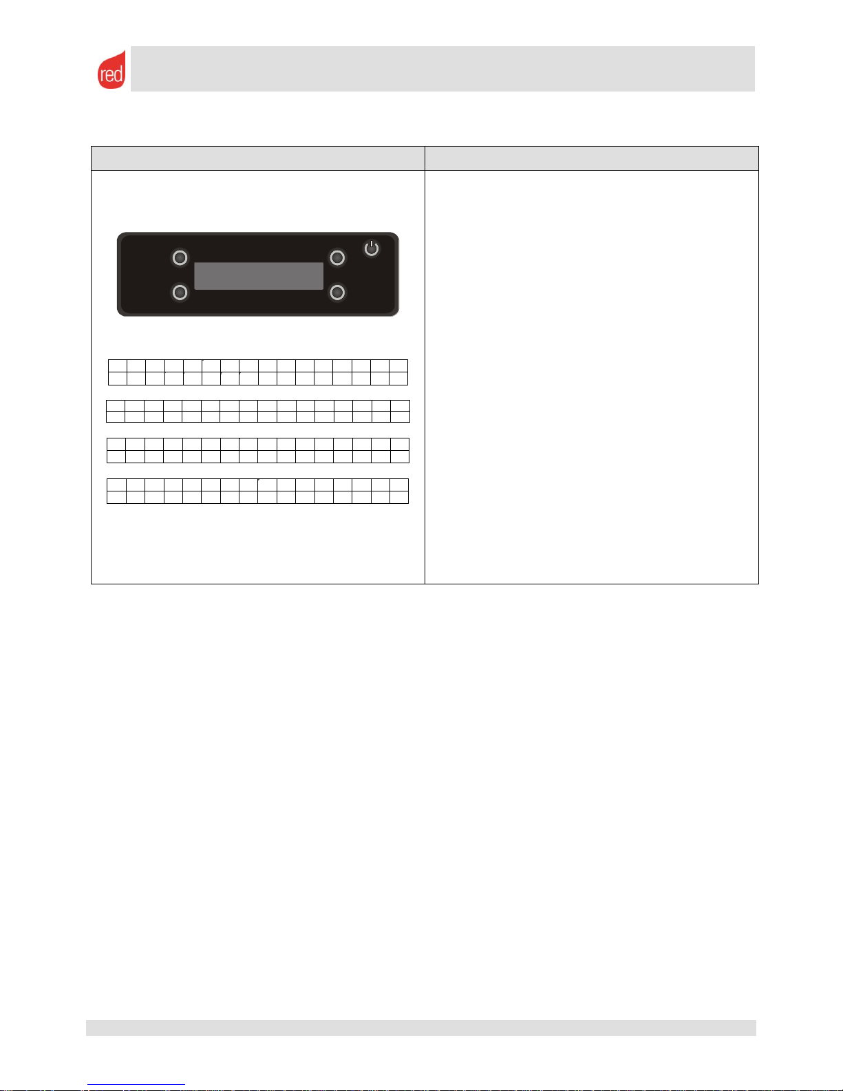
CONTROL PANEL
INSTRUCTIONS
M o d e : M A N U M e n u
F i r e : 1 F a n : 2
e s c S e t
< S e t t i n g >
e s c 0 S e t
- P e l l e t R e c i p e +
e s c - 2 O K
- P e l l e t R e c i p e +
1. Press the button at the TOP RIGHT of the display
to access the MENU.
2. Using the two keys at the bottom, scroll through the
various menus until you reach the SETTINGS
3. Press the button corresponding to the word SET.
4. Using the two keys at the bottom, scroll through the
various menus until you reach the PELLET
RECIPE menu.
5. Confirm by pressing the the button corresponding
to the SET key.
6. Modify the value using the bottom keys
corresponding to symbols + and -
7. Confirm by pressing the the button corresponding
to the OK key.
THE AVAILABLE VALUES ARE
- 5 = 25% decrease in pellets in all power levels.
- 4 = 20% decrease in pellets in all power levels.
- 3 = 15% decrease in pellets in all power levels.
- 2 = 10% decrease in pellets in all power levels.
- 1 = 5% decrease in pellets in all power levels.
0 = Standard adjustment by the manufacturer
1 = 5% increase in pellets in all power levels.
2 = 10% increase in pellets in all power levels.
3 = 15% increase in pellets in all power levels.
4 = 20% increase in pellets in all power levels.
5 = 25% increase in pellets in all power levels.
5.2. The adjustment of the smoke blower (optional on Practika, standard on Variomatic)
To improve smoke discharge in difficult installations or where the flue pipe does not have the required
characteristics (minimum draught 20 Pa) an additional smoke blower fan can be installed. This fan can be easily
Page 16
SERVICE MANUAL
page 16
Rev. 02
08/11 – M.C.
Service Manual – 8901118900 – EN
All rights reserved
managed by the control panel by modifying the intake power of the fan (in percentage) until the required draught
values are reached in the flue pipe or the correct operation.
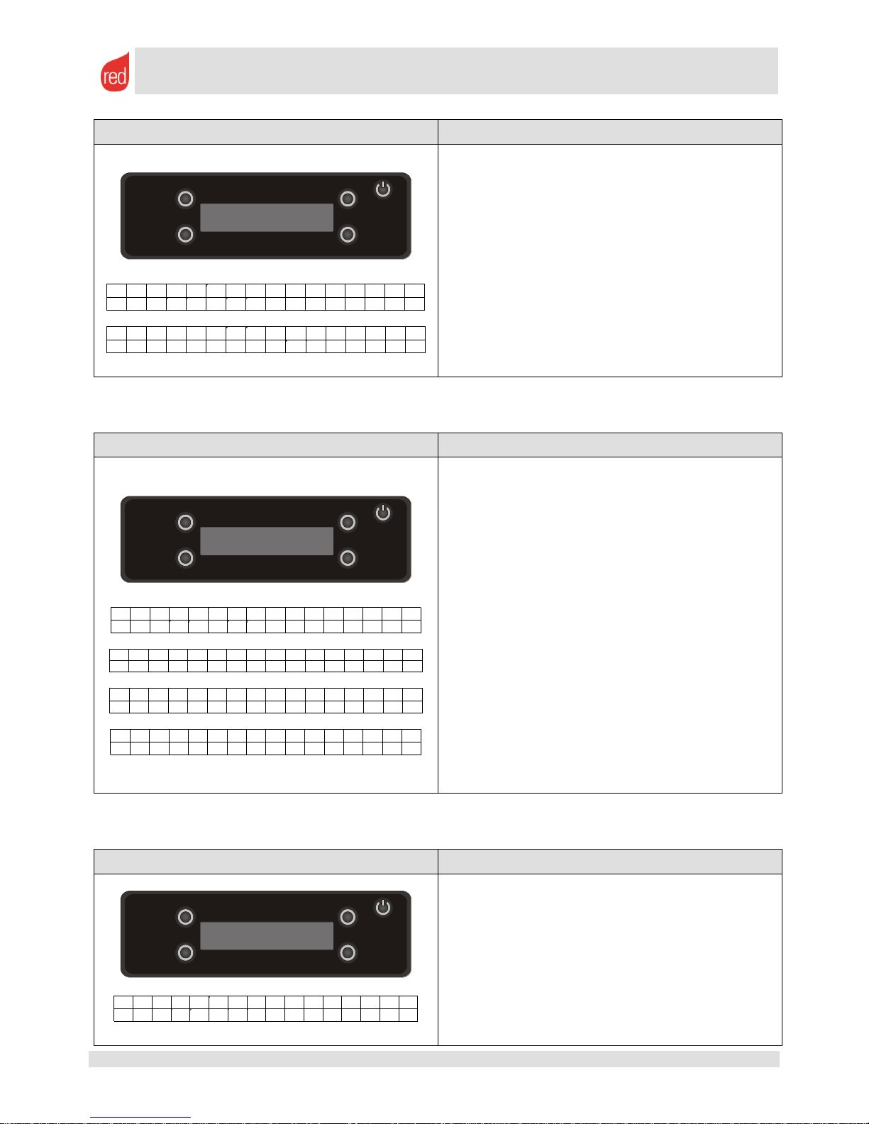
CONTROL PANEL
INSTRUCTIONS
F i r e : 5 M e n u
T . H 2 0 : 2 5 °
e s c S e t
< S e t t i n g >
e s c 0 S e t
- S m o k e B l o w e r O +
e s c - 2 O k
- S m o k e B l o w e r O +
1. Press the button at the TOP RIGHT of the display
to access the MENU
2. Using the two keys at the bottom, scroll through the
various menus until you reach the SETTINGS
menu.
3. Press the button corresponding to the word SET.
4. Using the two keys at the bottom, scroll through the
various menus until you reach the SMOKE BLOWER
OFFSET menu.
5. Confirm by pressing the the button corresponding
to the SET key.
6. Modify the value using the bottom keys
corresponding to symbols + and -
7. Confirm by pressing the the button corresponding
to the OK key.
THE AVAILABLE VALUES ARE
From -10 to +10
Each point corresponds to a 5% positive or negative
variation.
5.3. First ignition: what to check
Wash the system prior to installation and put the system into operation
Always carry out a preventative check of the number of radiators and the system's potential absorption.
Check the flow and return pipes, both in terms of the diameter and the insulation.
Check that all the cut-off cocks of the system are open or that the thermostats that control the solenoids in the
area permit opening (heat requirement from the thermostat)
The boiler must be connected to the hydraulic system, preferably using flexible pipes and inserting cut-off
cocks to isolate the appliance should it require maintenance.
Load the system with cold water using a filler cock.
Bring the pressure to 1.5 bar.
The pressure of the system can be checked using the pressure gauge supplied or the gauge already fitted on
the system, for example the gauge already fitted on the gas boiler
Check that there are no leaks from the hydraulic connections.
Check that the safety valve of the system is connected to a sewer drain.
Vent the air from the circuit using the associated valves that should be located along the system.
If there is an external thermostat ensure that it is correctly connected to the boiler.
Check the calibration of the water temperature in the boiler as indicated below:
Page 17
SERVICE MANUAL
page 17
Rev. 02
08/11 – M.C.
Service Manual – 8901118900 – EN
All rights reserved
CONTROL PANEL
INSTRUCTIONS
F i r e : 5 M e n u
T . H 2 0 : 2 5 °
e s c 6 5 ° C O k
- T e m p . H 2 0 +
1. Press the button at the BOTTOM LEFT of the
display to adjust the desired temperature of the
water in the boiler.
2. Modify the value using the bottom keys
corresponding to symbols + and -
3. Confirm by pressing the the button corresponding
to the OK key.
Use buttons + and - to bring the temperature to the
desired level. This temperature must NEVER BE
LOWER THAN 55 °C AND HIGHER THAN 80° C.
Below 55 °C there is a risk of generating condensation
while above 80 °C there is a risk of boiling.
The recommended temperature is 65 °C.
Activate the auger to transport pellets quickly along the duct until the pellets cannot be seen or heard falling
into the brazier. Operate as follows to carry out this operation:
CONTROL PANEL
INSTRUCTIONS
F i r e : 5 M e n u
T . H 2 0 : 2 5 °
e s c S e t
< S e t t i n g >
e s c O f f S e t
< L o a d p e l l e t >
e s c O n O k
< L o a d p e l l e t >
1. Press the button at the TOP RIGHT of the display
to access the MENU.
2. Using the two keys at the bottom, scroll through the
various menus until you reach the SETTINGS
menu.
3. Press the button corresponding to the word SET.
4. Using the two keys at the bottom, scroll through the
various menus until you reach the LOAD PELLET
5. Confirm by pressing the the button corresponding
to the SET key.
6. Select ON using the bottom keys corresponding to
symbols < and >
7. Confirm by pressing the the button corresponding
to the OK key.
8. As soon as the pellets can be seen/ heard select
OFF using the bottom keys corresponding to
symbols < and > to switch of the geared motor.
N.B. This menu is only visible when the boiler is set
to OFF.
Test the correct connection and operation of the water pump via the associated option on the control panel.
Operate as follows to carry out this operation:
CONTROL PANEL
INSTRUCTIONS
F i r e : 5 M e n u
T . H 2 0 : 2 5 °
1. Press the button at the TOP RIGHT of the display
to access the MENU.
2. Using the two keys at the bottom, scroll through the
various menus until you reach the SETTINGS
menu.
3. Press the button corresponding to the word SET.
4. Using the two keys at the bottom, scroll through the
various menus until you reach the START PUMP
5. Confirm by pressing the button corresponding to
Page 18

SERVICE MANUAL
page 18
Rev. 02
08/11 – M.C.
Service Manual – 8901118900 – EN
All rights reserved
e s c S e t
< S e t t i n g >
e s c O f f S e t
< S t a r t p u m p >
e s c O n O k
< S t a r t p u m p >
the SET key.
6. Select ON using the bottom keys corresponding to
symbols < and >
7. Confirm by pressing the button corresponding to
the OK key.
8. As soon as the correct water circulation and the
operation of the pump can be seen/ heard, select
OFF using the bottom keys corresponding to
symbols < and > to return to normal status.
Switch on the boiler and wait for the water in the boiler to arrive at the temperature set for activation of the
pump (standard 50 °C, can be modified in the associated menu). At this temperature the circulation pump
(water pump) begins to operate and the hot water begins to circulate in the system. When cold water from the
system returns to the boiler the temperature inside the boiler itself will rapidly drop and the circulation pump
will stop. This is perfectly normal and can last several minutes, depending on the size of the system. When all
the water inside the system reaches a temperature above the set value, the circulation pump will remain
permanently active. In the time interval before the pump activation temperature is reached, the pump will
switch on for 10 seconds every minute to mix the water inside the system.
As mentioned above, you can modify the temperature at which the pump intervenes by entering the setting
menu:
CONTROL PANEL
INSTRUCTIONS
F i r e : 5 M e n u
T . H 2 0 : 2 5 °
e s c S e t
< S e t t i n g >
e s c 5 0 ° C S e t
< T e m p . O N p u m p >
e s c 5 0 ° C O k
- T e m p . O N p u m p +
1. Press the button at the TOP RIGHT of the display
to access the menu.
2. Using the two keys at the bottom, scroll through the
various menus until you reach the SETTINGS
menu.
3. Press the button corresponding to the word SET.
4. Using the two keys at the bottom, scroll through the
various menus until you reach the TEMP.ON
PUMP
5. Confirm by pressing the button corresponding to
the SET key.
6. Modify the value using the bottom keys
corresponding to symbols + and -
7. Confirm by pressing the button corresponding to
the OK key.
5.3.1. External room thermostat
An external room thermostat can be connected to all appliances.
To do this, connect the thermostat to the serial port using the associated connector.
When an external thermostat is connected to the boiler the display shows T ON. Otherwise the display shows
T OFF.
No temperature measurement is shown on the display as there if no local room sensor. The boiler only waits for
the external thermostat to close or open the contact to switch on, switch off or alter its power. If there is no external
room thermostat the power will be fully dosed on the temperature of the water in the boiler.
In the same way, it is possible to connect an external water sensor (to insert in a puffer or accumulation tank, for
example) or a domotic control unit.
5.3.2. ECO-STOP mode
This function can be considered an "advanced automatic" mode that prompts the appliance to switch off when
the temperature is reached rather than simply reducing the minimum power (ECO).
We recommend that you DO NOT use the ECO-STOP function in rooms with minimal insulation or if cooling
in the installation room is very sudden. If used in these conditions the appliance will be forced to switch on and off
frequently.
Page 19

SERVICE MANUAL
page 19
Rev. 02
08/11 – M.C.
Service Manual – 8901118900 – EN
All rights reserved
CONTROL PANEL
INSTRUCTIONS
F i r e : 5 M e n u
T . H 2 0 : 2 5 °
e s c S e t
< S e t t i n g >
e s c O f f S e t
< E C O >
e s c O f f O k
< E C O >
1. Press the button at the TOP RIGHT of the display
to access the MENU.
2. Using the two keys at the bottom, scroll through the
various menus until you reach the SETTINGS
menu.
3. Press the button corresponding to the word SET.
4. Using the two keys at the bottom, scroll through the
various menus until you reach the ECO
5. Confirm by pressing the button corresponding to
the SET key.
6. Modify the value using the bottom keys
corresponding to symbols + and -
7. Confirm by pressing the button corresponding to
the OK key.
5.3.3. Water temperature differential
You can increase or decrease the temperature differential in the boilers to prevent the temperature of the water in
the boiler from exceeding a value determined and set by the user. This differential is set to 5 Cas standard.
Example: SET WATER TEMPERATURE = 65 °C
TEMPERATURE DIFFERENTIAL = 5 °C
At a temperature of 70 °C the stove stops in ECO-STOP mode to prevent the water in the boiler
from boiling.
To modify this parameter you must access the advanced settings in the TECHNICAL MENU – HYDRO MENU
(using the C93 password). For clearer instructions refer to chapter 5.5.
5.3.4. AUX contact
To allow functions combined with other heating devices there is an auxiliary contact on the motherboard (AUX1 or
AUX2). This contact can be used to set the temperature of the water in the boiler. Above this temperature a second
heat generator (if used) can be deactivated or an auxiliary contact can be opened.
CONTROL PANEL
INSTRUCTIONS
F i r e : 5 M e n u
T . H 2 0 : 2 5 °
e s c S e t
< S e t t i n g >
e s c 6 0 ° C S e t
< O f f A U X >
e s c 6 0 ° C O k
- O f f A U X +
1. Press the button at the TOP RIGHT of the display
to access the MENU.
2. Using the two keys at the bottom, scroll through the
various menus until you reach the SETTINGS
menu.
3. Press the button corresponding to the word SET.
4. Using the two keys at the bottom, scroll through the
various menus until you reach the OFF AUX
5. Confirm by pressing the button corresponding to
the SET key.
6. Modify the temperature value using the bottom
keys corresponding to symbols + and -
7. Confirm by pressing the button corresponding to
the OK key.
Page 20

SERVICE MANUAL
page 20
Rev. 02
08/11 – M.C.
Service Manual – 8901118900 – EN
All rights reserved
5.3.5. Testing individual components
Individual components can be activated to check their function via the TECHNICAL MENU
CONTROL PANEL
INSTRUCTIONS
F i r e : 5 M e n u
T . H 2 0 : 2 5 °
e s c S e t
< T e c h n i c a l m e n u >
e s c S e t
< M e n u t e s t >
1. Press the button at the TOP RIGHT of the display (2)
to access the MENU.
2. Using the two keys at the bottom, scroll through the
various menus until you reach the TECHNICAL
MENU
3. Press the button corresponding to the word SET.
4. Insert password C93
5. Press the button corresponding to the word SET.
6. Using the two keys at the bottom, scroll through the
various menus until you reach the MENU TEST
7. Press the button corresponding to the word SET.
8. Choose which of the following components to activate:
o Auger
o Smoke Blower
o Pump
o Pellet igniter
9. Press the button corresponding to the word OK.
10. Perform the same operation in reverse to switch off the
component
5.3.6. Regular operation
Once the boiler reaches regular operation is autonomously chooses to decrease the operating power depending
on whether the thermostats request heat.
THE BOILER OPERATES ONLY IN AUTOMATIC MODE (MANUAL mode does not exist)
The boiler goes into ECO mode (minimum power) when one or both of the temperatures requested (water and air)
have been satisfied.
5.4. Information about the operation of the appliance
You can retrieve information about the operation of the appliance while is it switched on or during some specific
operating phases. This information is often fundamental to solving problems or correctly diagnosing faults.
CONTROL PANEL
INSTRUCTIONS
F i r e : 5 M e n u
T . H 2 0 : 2 5 °
e s c S e t
< I n f o >
1. Press the button at the TOP RIGHT of the display
(2) to access the MENU.
2. Using the two keys at the bottom, scroll through the
various menus until you reach the INFO menu.
3. Press the button corresponding to the word SET.
4. Using the two keys at the bottom, scroll through the
various menus to view the information. Specifically,
this information may concern:
o The motherboard code
o The motherboard safety code
o The display code
o The boiler operating times
o The service time counter
o The no. of revolutions (RPM) of the smoke
blower
o The auger start-up time
o The photo resistance level.
Page 21

SERVICE MANUAL
page 21
Rev. 02
08/11 – M.C.
Service Manual – 8901118900 – EN
All rights reserved
5.5. Special settings on boilers – TECHNICAL MENU
The technical menu of the boiler allows you to modify various settings that we recommend you alter only if strictly
necessary. ACCESS PASSWORD FOR THE TECHNICAL MENU: C 93
MAIN MENU
SUBMENU
INFORMATION NOTES
GENERAL SETTINGS
BOILER TYPE
Boiler model (Practika 28-33 or Variomatic)
ZEROING THE SERVICE TIMES
Zeroing the counter for unscheduled maintenance at 2000
hours
ECO MENU
WAITING ON
Standard 20 min. Waiting prior to start-up in ECO mode
WAITING OFF
Standard 20 min. Waiting prior to shut down in ECO mode
AUGER MENU
AUGER BRAKING
Standard ON. Electrical signal to instantly stop the geared
motor
OFFSET IN START-UP
Standard +5. Increase or decrease in pellet load in start-up
T.ON P.MIN
Standard 2.0 sec. Start-up time in seconds of the auger at
minimum power
T.ON P.MAX
Standard 6.5 sec. Start-up time in seconds of the auger at
maximum power
BLOWER MENU
OFFSET IN START-UP
Standard +10. Increase or decrease in pellet load in start-
up
MIN P. RPM
Standard 1700 rpm. Start-up time in seconds of the smoke
blower fan at minimum power
MAX P. RPM
Standard 2750 rpm. Start-up time in seconds of the smoke
blower fan at maximum power.
SECOND BLOWER MENU
START-UP
Start-up temperature
SHUT DOWN
Shut down temperature
LEVEL 1
Speed at minimum power
LEVEL 5
Speed at maximum power
HYDRO MENU
HYDRO SHUT DOWN
Activation of ECO-STOP controlled by the temperatures of
the water in the boiler when the boiler exceeds hysteresis
WATER TEMPERATURE
HYSTERESIS
Standard 5 °C. Delta temperature HYDRO SHUT DOWN
intervention
SHAKER MENU
Only for VARIOMATIC model
SHAKER
Standard ON. Activation of the brazier cleaning shaker
(Variomatic model)
INTERVAL BETWEEN CYCLES
Standard 0.5 h
NO. OF CYCLES
Standard 2
CYCLE DURATION
Standard 60 sec.
START-UP MENU
PRE-IGNITION DURATION
Standard 20 sec
START-UP DURATION
Standard 600 sec.
FIRE-ON DURATION
Standard 120 sec
PHOTORESISTANCE ON
3346. Value to consider the boiler as switched on
PHOTORESISTANCE OFF
7665. Value to consider the boiler as switched off
BRAZIER CLEANING MENU
POWER THRESHOLD
Standard 3. Threshold to distinguish the cleaning operation
intensive or reduced
P. WAITING NORMAL
Standard 1800 sec. Interval between two cleaning events
P. DURATION NORMAL
Standard 60 sec. Cleaning duration normal
P. WAITING REDUCED
Standard 1800 sec. Interval between two cleaning events
P. DURATION REDUCED
Standard 20 sec. Reduced cleaning duration
TEST MENU
AUGER
Supply of the geared motor/ auger to test its operation
SMOKE BLOWER
Supply of the smoke blower fan to test its operation
PUMP
Supply of the water pump to test its operation
PELLET IGNITER
Supply of the pellet igniter to test its operation
Page 22

SERVICE MANUAL
page 22
Rev. 02
08/11 – M.C.
Service Manual – 8901118900 – EN
All rights reserved
6. Technical parameters.
The technical parameters constitute all of the information and timeframes that the appliance must adhere to to
operate correctly. You can make modifications to improve various aspects of operation such as consumption,
frequency of regular cleaning, smoke discharge, etc. but we recommend that you perform these variations only if
you are certain of the consequences.
Below is an explanation of how to access these parameters, which are protected with a password, and how to
modify them if necessary.
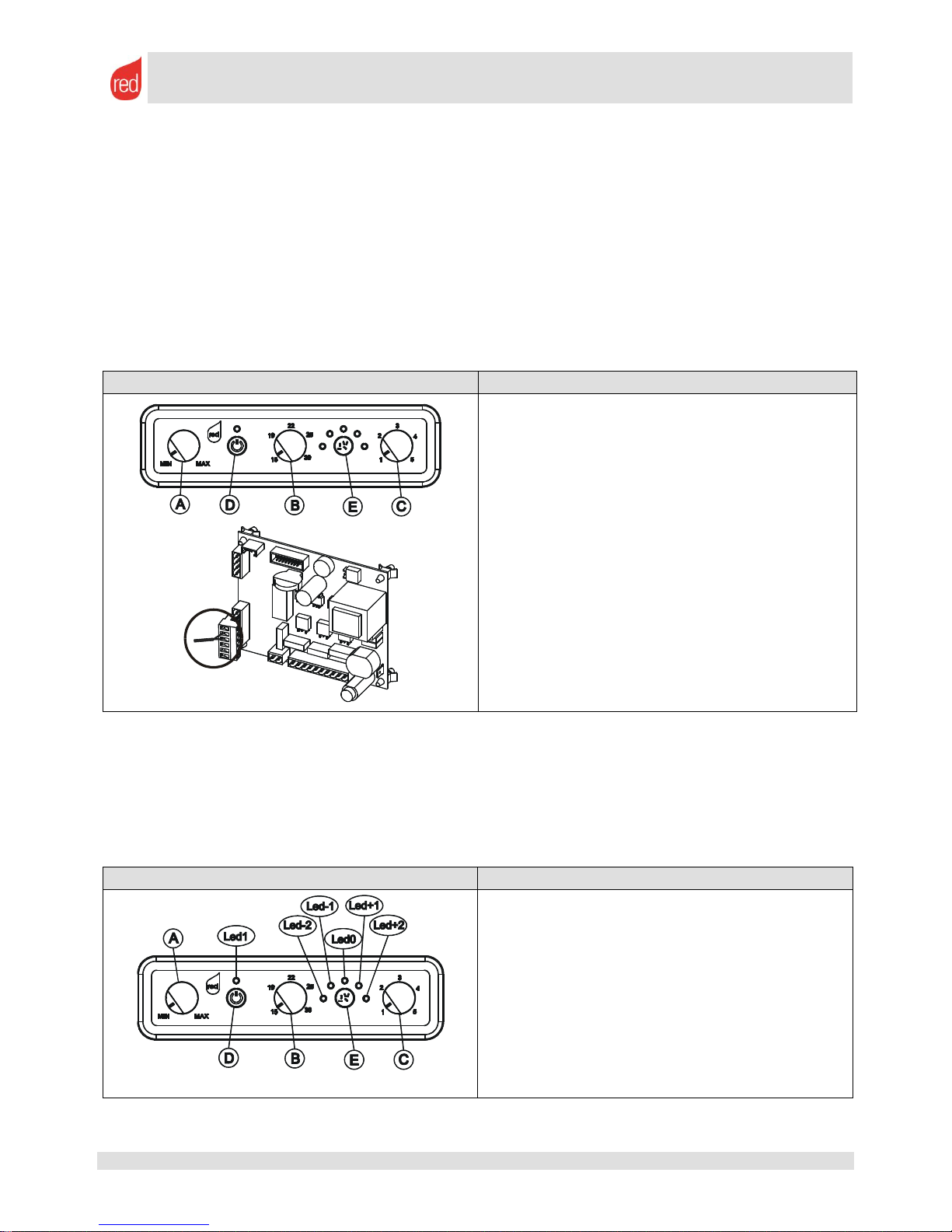
6.1. How to access technical parameters
CONTROL PANEL
INSTRUCTIONS
The control panel for RED AIR and MULTIAIR stoves
does not allow you to access the technical
parameters as there is no display.
However, this difficulty can be overcome by temporarily
replacing the control panel with a panel that includes an
LCD display such as that used for MCZ MERCURY (code
4160388) model stoves. Once this panel has been fitted,
follow the instructions below:
Press the menu key and press the buttons until you
reach MENU 9
Press the MENU button to gain access
Enter the password (A9) using buttons or
Confirm the password by pressing the MENU button.
Use button to scroll between the various parameters
Use buttons or to modify the parameters
We recommend that you refit the standard panel after
performing the necessary variations.
1. Press buttons and at the same time to access
UT01
2. Press button three times to access parameter UT04
3. Enter the password (A9) using buttons or
4. Confirm the password by pressing .
5. Use button to scroll through the various parameters
6. Use buttons or to modify the parameters
1. Press the button at the TOP RIGHT to access the
MENU.
2. Using the two keys at the bottom, scroll through the
various menus until you reach the SETTINGS menu.
3. Press the button corresponding to the word SET.
4. Using the two keys at the bottom, scroll through the
various menus until you reach the TECHNICAL
MENU
5. Press the button corresponding to the word SET and
enter the password C 93 using the keys at the bottom.
Confirm the letter and number using OK.
6. Confirm by pressing the the button corresponding to
the SET key.
7. Navigate within the various menus illustrated in the
previous chapter5.5. Special settings on boilers –
TECHNICAL MENU
SET
TURBO
1
2
6 4
3
5
!
Page 23

SERVICE MANUAL
page 23
Rev. 02
08/11 – M.C.
Service Manual – 8901118900 – EN
All rights reserved
6.2. Stove parameters
Parameters for RED AIR 6 kW – DALIA stoves
Parameters/ Databases
LED -2
LED -1
LED 0
LED +1
LED +2
01: max start-up time (min)
15
02: Fire On (min)
2
03: Interval between brazier cleanings (min)
20*
04: Load wood auger ON (sec)
-30% pellet
-15% pellet
3
+5% pellet
+10% pellet
05: Fire On auger ON (sec)
-30% pellet
-15% pellet
3
+5% pellet
+10% pellet
06: Auger on at Power 1 (sec) **
-30% pellet
-15% pellet
1.5
+5% pellet
+10% pellet
07: Auger on at Power 2 (sec) **
-30% pellet
-15% pellet
1.9
+5% pellet
+10% pellet
08: Auger on at Power 3 (sec)
-30% pellet
-15% pellet
2.3
+5% pellet
+10% pellet
09: Auger on at Power 4 (sec)
-30% pellet
-15% pellet
2.7
+5% pellet
+10% pellet
10: Auger on at Power 5 (sec)
-30% pellet
-15% pellet
3
+5% pellet
+10% pellet
11: Shut down revolutions after alarm (g/1 minute)
1100
12:duration of brazier cleaning (sec)
30
13. minimum temperature for the start-up phase (C°)
50
14: max smoke temperature threshold for modulation (C°)
240
15: temperature for starting up and shutting down the
exchanger (C°)
60
16: speed of smoke suction in Load wood (g/1 min)
1403
1556
1700
1845
1998
17: speed of smoke suction in Fire On (g/1 min)
1155
1281
1400
1519
1645
18: speed of smoke suction at Power 1 g/1 min)
825
915
1000
1085
1175
19: speed of smoke suction at Power 2 g/1 min)
908
1007
1100
1194
1293
20: speed of smoke suction at Power 3 (g/1 min)
990
1098
1200
1302
1410
21: speed of smoke suction at Power 4 g/1 min)
1073
1190
1300
1411
1528
22: speed of smoke suction at Power 5 g/1 min)
1155
1281
1400
1519
1645
23: speed of exchanger 1
30
24: speed of exchanger 2
32
25: speed of exchanger 3
34
26: speed of exchanger 4
36
27: speed of exchanger 5
68
28: speed of smoke suction in brazier cleaning
2500
29: delay of eco-stop restarting (N.P.=Not Present)
5
30: Delta °C
5
Parameters for RED AIR 8 kW – MARGHERITA / GARDENIA stoves
Parameters/ Databases
LED -2
LED -1
LED 0
LED +1
LED +2
01: max start-up time (min)
15
02: Fire On (min)
2
03: Interval between brazier cleaning (min)
20*
04: Load wood auger ON (sec)
-30% pellet
-15% pellet
3.4
+5% pellet
+10% pellet
05: Fire On auger ON (sec)
-30% pellet
-15% pellet
3.4
+5% pellet
+10% pellet
06: Auger on at Power 1 (sec) **
-30% pellet
-15% pellet
2.3
+5% pellet
+10% pellet
07: Auger on at Power 2 (sec) **
-30% pellet
-15% pellet
3.2
+5% pellet
+10% pellet
08: Auger on at Power 3 (sec)
-30% pellet
-15% pellet
4.1
+5% pellet
+10% pellet
09: Auger on at Power 4 (sec)
-30% pellet
-15% pellet
4.9
+5% pellet
+10% pellet
10: Auger on at Power 5 (sec)
-30% pellet
-15% pellet
5.8
+5% pellet
+10% pellet
11: Shut down revolutions after alarm (g/1 minute)
1100
12:duration of brazier cleaning (sec)
30**
13. minimum temperature for the start-up phase (C°)
50
14: max smoke temperature threshold for modulation (C°)
190
15: temperature for starting up and shutting down the
exchanger (C°)
60
16: speed of smoke suction in Load wood (g/1 min)
1568
1739
1900
2062
2233
17: speed of smoke suction in Fire On (g/1 min)
1238
1373
1500
1628
1763
18: speed of smoke suction at Power 1 g/1 min)
1155
1281
1400
1519
1645
19: speed of smoke suction at Power 2 g/1 min)
1279
1418
1550
1682
1821
20: speed of smoke suction at Power 3 (g/1 min)
1403
1556
1700
1845
1998
21: speed of smoke suction at Power 4 g/1 min)
1526
1693
1850
2007
2174
22: speed of smoke suction at Power 5 g/1 min)
1650
1830
2000
2170
2350
23: speed of exchanger 1
30
24: speed of exchanger 2
32
25: speed of exchanger 3
34
26: speed of exchanger 4
36
27: speed of exchanger 5
68
28: speed of smoke suction in brazier cleaning
2500
29: delay of eco-stop restarting (N.P.=Not Present)
5
30: Delta °C
5
Page 24

SERVICE MANUAL
page 24
Rev. 02
08/11 – M.C.
Service Manual – 8901118900 – EN
All rights reserved
Parameters for RED AIR 9.5 kW – PRIMULA / ORCHIDEA stoves
Parameters/ Databases
LED -2
LED -1
LED 0
LED +1
LED +2
01: max start-up time (min)
15
02: Fire On (min)
2
03: Interval between brazier cleaning (min)
20*
04: Load wood auger ON (sec)
-30% pellet
-15% pellet
3.4
+5% pellet
+10% pellet
05: Fire On auger ON (sec)
-30% pellet
-15% pellet
3.4
+5% pellet
+10% pellet
06: Auger on at Power 1 (sec) **
-30% pellet
-15% pellet
2.3
+5% pellet
+10% pellet
07: Auger on at Power 2 (sec) **
-30% pellet
-15% pellet
3.3
+5% pellet
+10% pellet
08: Auger on at Power 3 (sec)
-30% pellet
-15% pellet
4.3
+5% pellet
+10% pellet
09: Auger on at Power 4 (sec)
-30% pellet
-15% pellet
5.2
+5% pellet
+10% pellet
10: Auger on at Power 5 (sec)
-30% pellet
-15% pellet
6.2
+5% pellet
+10% pellet
11: Shut down revolutions after alarm (g/1 minute)
1100
12:duration of brazier cleaning (sec)
30*
13. minimum temperature for the start-up phase (C°)
50
14: max smoke temperature threshold for modulation (C°)
200
15: temperature for starting up and shutting down the
exchanger (C°)
60
16: speed of smoke suction in Load wood (g/1 min)
1568
1739
1900
2062
2233
17: speed of smoke suction in Fire On (g/1 min)
1238
1373
1500
1628
1763
18: speed of smoke suction at Power 1 g/1 min)
1155
1281
1400
1519
1645
19: speed of smoke suction at Power 2 g/1 min)
1361
1510
1650
1790
1939
20: speed of smoke suction at Power 3 (g/1 min)
1485
1647
1800
1953
2115
21: speed of smoke suction at Power 4 g/1 min)
1609
1784
1950
2116
2291
22: speed of smoke suction at Power 5 g/1 min)
1733
1922
2100
2279
2468
23: speed of exchanger 1
30
24: speed of exchanger 2
32
25: speed of exchanger 3
36
26: speed of exchanger 4
40
27: speed of exchanger 5
68
28: speed of smoke suction in brazier cleaning
2500
29: delay of eco-stop restarting (N.P.=Not Present)
5
30: Delta °C 5
Parameters for RED MULTIAIR 11 kW – PRIMULA / ORCHIDEA stoves
Parameters/ Databases
LED -2
LED -1
LED 0
LED +1
LED +2
01: max start-up time (min)
15
02: Fire On (min)
2
03: Interval between brazier cleaning (min)
20*
04: Load wood auger ON (sec)
-30% pellet
-15% pellet
3.4
+5% pellet
+10% pellet
05: Fire On auger ON (sec)
-30% pellet
-15% pellet
3.4
+5% pellet
+10% pellet
06: Auger on at Power 1 (sec) **
-30% pellet
-15% pellet
2.4
+5% pellet
+10% pellet
07: Auger on at Power 2 (sec) **
-30% pellet
-15% pellet
3.5
+5% pellet
+10% pellet
08: Auger on at Power 3 (sec)
-30% pellet
-15% pellet
4.6
+5% pellet
+10% pellet
09: Auger on at Power 4 (sec)
-30% pellet
-15% pellet
5.6
+5% pellet
+10% pellet
10: Auger on at Power 5 (sec)
-30% pellet
-15% pellet
6.7
+5% pellet
+10% pellet
11: Shut down revolutions after alarm (g/1 minute)
1100
12:duration of brazier cleaning (sec)
45*
13. minimum temperature for the start-up phase (C°)
50
14: max smoke temperature threshold for modulation (C°)
210
15: temperature for starting up and shutting down the
exchanger (C°)
60
16: speed of smoke suction in Load wood (g/1 min)
1568
1739
1900
2062
2233
17: speed of smoke suction in Fire On (g/1 min)
1238
1373
1500
1628
1763
18: speed of smoke suction at Power 1 g/1 min)
1155
1281
1400
1519
1645
19: speed of smoke suction at Power 2 g/1 min)
1320
1464
1600
1736
1880
20: speed of smoke suction at Power 3 (g/1 min)
1485
1647
1800
1953
2115
21: speed of smoke suction at Power 4 g/1 min)
1650
1830
2000
2170
2350
22: speed of smoke suction at Power 5 g/1 min)
1815
2013
2200
2387
2585
23: speed of exchanger 1
21
24: speed of exchanger 2
29
25: speed of exchanger 3
45
26: speed of exchanger 4
55
27: speed of exchanger 5
68
28: speed of smoke suction in brazier cleaning
2500
29: delay of eco-stop restarting (N.P.=Not Present)
5
30: Delta °C 5
Page 25

SERVICE MANUAL
page 25
Rev. 02
08/11 – M.C.
Service Manual – 8901118900 – EN
All rights reserved
Parameters for RED HYDRO 11.6 kW – MARGHERITA / GARDENIA stoves
Parameters in UT04 – Password A9
+3
+2
+1 0 -1
-2
-3
01:Load wood (min)
15
15
15
15
15
15
15
02: Fire On (min)
2 2 2 2 2 2 2
03: Interval between brazier cleaning (min)
20
20
20
20
20
20
20
04: Load wood auger ON (sec)
1.8
1.8
1.7
1.6
1.4
1.3
1.1
05: Fire On auger ON (sec)
1.8
1.8
1.7
1.6
1.4
1.3
1.1
06: Auger on at Power 1 (sec) **
1.4
1.3
1.3
1.2
1.1
1.0
0.8
07: Auger on at Power 2 (sec) **
1.8
1.8
1.7
1.6
1.4
1.3
1.1
08: Auger on at Power 3 (sec)
2.5
2.4
2.3
2.2
2.0
1.8
1.5
09: Auger on at Power 4 (sec)
3.2
3.1
2.9
2.8
2.5
2.2
2.0
10: Auger on at Power 5 (sec)
3.9
3.7
3.6
3.4
3.1
2.7
2.4
11:smoke suction parameter when switched off
1000
1000
1000
1000
1000
1000
1000
12:duration of brazier cleaning (sec)
30*
30*
30*
30*
30*
30*
30*
13. minimum temperature for the start-up phase (C°)
45
45
45
45
45
45
45
14:max temperature per modulation (C°) Eco phase
230
230
230
230
230
230
230
15: temperature for starting up and shutting down the
exchanger (C°)
--
--
--
--
--
--
--
16:smoke suction parameter in Load wood (rpm)
1900
1900
1900
2000
1900
1900
1900
17:smoke suction parameter in Fire On (rpm)
1900
1900
1900
1800
1900
1900
1900
18:smoke suction parameter at power 1 (rpm)
1300
1300
1300
1300
1300
1300
1300
19:smoke suction parameter at power 2 (rpm)
1500
1500
1500
1500
1500
1500
1500
20:smoke suction parameter at power 3 (rpm)
1700
1700
1700
1700
1700
1700
1700
21:smoke suction parameter at power 4 (rpm)
1900
1900
1900
1900
1900
1900
1900
22:smoke suction parameter at power 5 (rpm)
2100
2100
2100
2100
2100
2100
2100
23: speed of exchanger at power 1
----
----
----
----
----
----
----
24:speed of exchanger at power 2
----
----
----
----
----
----
----
25: speed of exchanger Power 3
----
----
----
----
----
----
----
26:speed of exchanger at power 4
----
----
----
----
----
----
----
27:speed of exchanger at power 5
----
----
----
----
----
----
----
28:temperature of pump activation
50
50
50
50
50
50
50
Parameters in UT04 – Password B9:
54:Auger on at domestic Power (sec)
----
----
----
----
----
----
----
55:smoke suction parameter at domestic Power (rpm)
----
----
----
----
----
----
----
56:smoke suction parameter in brazier cleaning (rpm)
2300
2300
2300
2300
2300
2300
2300
57:temperature for restarting in eco-stop
80
80
80
80
80
80
80
58:start-up differential when warm (C°)
5 5 5 5 5 5 5
Parameter in UT04 – Password P0:
calibration of the extractor rpm (permitted values: -2.-
1.0.1.2)
0 0 0 0 0 0 0
Parameter in UT04 – Password P2:
Pressure transducer (1 active - 0 deactivated)
0 0 0 0 0 0 0
Page 26

SERVICE MANUAL
page 26
Rev. 02
08/11 – M.C.
Service Manual – 8901118900 – EN
All rights reserved
Parameters for RED HYDRO 22 kW – PRIMULA / ORCHIDEA stoves
Parameters in UT04 – Password A9
+3
+2
+1 0 -1
-2
-3
01:Load wood (min)
15
15
15
15
15
15
15
02: Fire On (min)
2 2 2 2 2 2 2
03: Interval between brazier cleaning (min)
20
20
20
20
20
20
20
04: Load wood auger ON (sec)
2.1
2.0
1.9
1.8
1.6
1.4
1.3
05: Fire On auger ON (sec)
2.1
2.0
1.9
1.8
1.6
1.4
1.3
06: Auger on at Power 1 (sec) **
1.4
1.3
1.3
1.2
1.1
1.0
0.8
07: Auger on at Power 2 (sec) **
2.5
2.4
2.3
2.2
2.0
1.8
1.5
08: Auger on at Power 3 (sec)
3.7
3.5
3.4
3.2
2.9
2.6
2.2
09: Auger on at Power 4 (sec)
4.8
4.6
4.4
4.2
3.8
3.4
2.9
10: Auger on at Power 5 (sec)
6.0
5.7
5.5
5.2
4.7
4.2
3.6
11:smoke suction parameter when switched off
1000
1000
1000
1000
1000
1000
1000
12:duration of brazier cleaning (sec)
30*
30*
30*
30*
30*
30*
30*
13. minimum temperature for the start-up phase (C°)
50
50
50
50
50
50
50
14:max temperature per modulation (C°) Eco phase
230
230
230
230
230
230
230
15: temperature for starting up and shutting down the
exchanger (C°)
100
100
100
100
100
100
100
16:smoke suction parameter in Load wood (rpm)
1600
1600
1600
1600
1600
1600
1600
17:smoke suction parameter in Fire On (rpm)
1600
1600
1600
1600
1600
1600
1600
18:smoke suction parameter at power 1 (rpm)
1100
1100
1100
1100
1100
1100
1100
19:smoke suction parameter at power 2 (rpm)
1380
1380
1380
1380
1380
1380
1380
20:smoke suction parameter at power 3 (rpm)
1650
1650
1650
1650
1650
1650
1650
21:smoke suction parameter at power 4 (rpm)
1930
1930
1930
1930
1930
1930
1930
22:smoke suction parameter at power 5 (rpm)
2200
2200
2200
2200
2200
2200
2200
23: speed of exchanger at power 1
12
12
12
12
12
12
12
24:speed of exchanger at power 2
14
14
14
14
14
14
14
25: speed of exchanger Power 3
18
18
18
18
18
18
18
26:speed of exchanger at power 4
22
22
22
22
22
22
22
27:speed of exchanger at power 5
26
26
26
26
26
26
26
28:temperature of pump activation
50
50
50
50
50
50
50
Parameters in UT04 – Password B9:
54:Auger on at domestic Power (sec)
----
----
----
----
----
----
----
55:smoke suction parameter at domestic Power (rpm)
----
----
----
----
----
----
----
56:smoke suction parameter in brazier cleaning (rpm)
2300
2300
2300
2300
2300
2300
2300
57:temperature for restarting in eco-stop
80
80
80
80
80
80
80
58:start-up differential when warm (C°)
5 5 5 5 5 5 5
Parameter in UT04 – Password P0:
calibration of the extractor rpm (permitted values: -2.-
1.0.1.2)
0 0 0 0 0 0 0
Parameter in UT04 – Password P2:
Pressure transducer (1 active - 0 deactivated)
0 0 0 0 0 0 0
Page 27

SERVICE MANUAL
page 27
Rev. 02
08/11 – M.C.
Service Manual – 8901118900 – EN
All rights reserved
6.3. Boiler parameters
Parameters for COMPACT 24 boilers
Parameters in UT04 – Password A9
+3
+2
+1 0 -1
-2
-3
01:Load wood (min)
20
20
20
20
20
20
20
02: Fire On (min)
2 2 2 2 2 2 2
03: Interval between brazier cleaning (min)
20
20
20
20
20
20
20
04: Load wood auger ON (sec)
3.5
3.3
3.2
3.0
2.7
2.4
2.1
05: Fire On auger ON (sec)
2.9
2.8
2.6
2.5
2.3
2.0
1.8
06: Auger on at Power 1 (sec) **
1.7
1.7
1.6
1.5
1.4
1.2
1.1
07: Auger on at Power 2 (sec) **
3.0
2.8
2.7
2.6
2.3
2.1
1.8
08: Auger on at Power 3 (sec)
4.2
4.0
3.8
3.7
3.3
2.9
2.6
09: Auger on at Power 4 (sec)
5.4
5.2
5.0
4.7
4.3
3.8
3.3
10: Auger on at Power 5 (sec)
6.7
6.4
6.1
5.8
5.2
4.6
4.1
11:smoke suction parameter when switched off
1000
1000
1000
1000
1000
1000
1000
12:duration of brazier cleaning (sec)
30*
30*
30*
30*
30*
30*
30*
13. minimum temperature for the start-up phase (C°)
40
40
40
40
40
40
40
14:max temperature per modulation (C°) Eco phase
230
230
230
230
230
230
230
15: temperature for starting up and shutting down the
exchanger (C°)
100
100
100
100
100
100
100
16:smoke suction parameter in Load wood (rpm)
1900
1900
1900
1900
1900
1900
1900
17:smoke suction parameter in Fire On (rpm)
1600
1600
1600
1600
1600
1600
1600
18:smoke suction parameter at power 1 (rpm)
1300
1300
1300
1300
1300
1300
1300
19:smoke suction parameter at power 2 (rpm)
1530
1530
1530
1530
1530
1530
1530
20:smoke suction parameter at power 3 (rpm)
1750
1750
1750
1750
1750
1750
1750
21:smoke suction parameter at power 4 (rpm)
1980
1980
1980
1980
1980
1980
1980
22:smoke suction parameter at power 5 (rpm)
2200
2200
2200
2200
2200
2200
2200
23: speed of exchanger at power 1
--
--
--
--
--
--
--
24:speed of exchanger at power 2
--
--
--
--
--
--
--
25: speed of exchanger Power 3
--
--
--
--
--
--
--
26:speed of exchanger at power 4
--
--
--
--
--
--
--
27:speed of exchanger at power 5
--
--
--
--
--
--
--
28:temperature of pump activation
55
55
55
55
55
55
55
Parameters in UT04 – Password B9:
54:Auger on at domestic Power (sec)
6.9
6.6
6.3
6.0
5.4
4.8
4.2
55:smoke suction parameter at domestic Power (rpm)
2350
2350
2350
2350
2350
2350
2350
56:smoke suction parameter in brazier cleaning (rpm)
2750
2750
2750
2750
2750
2750
2750
57:temperature for restarting in eco-stop
80
80
80
80
80
80
80
58:start-up differential when warm (C°)
5 5 5 5 5 5 5
Parameter in UT04 – Password P0:
calibration of the extractor rpm (permitted values: -2.-
1.0.1.2)
0 0 0 0 0 0 0
Parameter in UT04 – Password P2:
Pressure transducer (1 active - 0 deactivated)
0 0 0 0 0 0 0
Page 28

SERVICE MANUAL
page 28
Rev. 02
08/11 – M.C.
Service Manual – 8901118900 – EN
All rights reserved
Parameters for PRACTIKA – VARIOMATIC boilers
Parameters/ Databases
Practika 28
Practika 33
Variomatic 33
Unit
Stove Type 1 2 3
Motor Type 8 8 8
RPM Control
Yes
Yes
Yes
Minimum RPM Limitor
Yes
Yes
Yes
Auger braking
Yes
Yes
No
Room Thermostat
Yes
Yes
Yes
Photoresistance start-up
Yes
Yes
No
Hydro mode
Yes
Yes
Yes
Shaker
No
No
Yes
Blower 2
Yes
Yes
Yes
Independent Hydro
No
No
No
Hydro shut down
Yes
Yes
Yes
Puffer / EC Pump
No
No
No
T. Set On Pump
40
40
40
[°C]
Water Temp. Hysteresis
5 5 5
[°C]
Delta Temp. Off Pump
4 4 4
[°C]
Temp. H2O Aux.
50
50
50
[°C]
Number of Cycles
N.A.
N.A. 2
Interval of Cycles
N.A.
N.A. 3 [h.]
Cycle Duration
N.A.
N.A.
30
[sec.]
Blower 2: Start-up 1
21
21
21
Blower 2: Start-up 2
21
21
21
Blower 2: Shut down 1
19
19
19
Blower 2: Shut down 2
19
19
19
Blower 2: Level 1
19
19
19
Blower 2: Level 2
21
21
21
Blower 2: Level 3
23
23
23
Blower 2: Level 4
25
25
25
Blower 2: Level 5
27
27
27
Set Fire 5 5 5
T. H2O
65
65
70
Blower Offset: Transistory Activations
0 0 0
Blower Offset: Power Activations
0 0 0
Pellet Recipe: Transistory Activations
0 0 0
Pellet Recipe: Power Activations
0 0 0
Eco Function: Eco On/Off
Yes
Yes
Yes
Eco Function: Waiting time On
5 5 5
[min.]
Eco Function: Waiting time Off
20
20
20
[min.]
Pre-Alarm Smoke time
N.A.
N.A.
250
Max. Duration of pre-alarm
N.A.
N.A.
600
Pre-alarm Hysteresis
N.A.
N.A. 5
Alarm Smoke time
N.A.
N.A.
270
Stove Off: Auger
No
No
No
Stove Off: Igniter
No
No
No
Stove Off: Blower 2
No
No
No
Stove Off: Igniter
No
No
No
Stove Off: Time On auger
0 0 0
[sec.]
Stove Off: Blower
300
300
300
[rpm]
Pre-ignition 1: Auger
No
No
No
Pre-ignition 1: Igniter
Yes
Yes
Yes
Pre-ignition 1: Blower 2
Yes
Yes
Yes
Pre-ignition 1: Blower
Yes
Yes
Yes
Pre-ignition 1: Time On auger
0 0 0
[sec.]
Pre-ignition 1: Blower
2750
2750
2750
[rpm]
Pre-ignition 2: Auger
Yes
Yes
Yes
Pre-ignition 2: Igniter
Yes
Yes
Yes
Pre-ignition 2: Blower 2
Yes
Yes
Yes
Pre-ignition 2: Blower
Yes
Yes
Yes
Pre-ignition 2: Time On auger
12
12
12
[sec.]
Pre-ignition 2: Blower
1000
1000
2000
[rpm]
Start-up A: Auger
Yes
Yes
Yes
Start-up A: Igniter
Yes
Yes
Yes
Start-up A: Blower 2
Yes
Yes
Yes
Start-up A: Blower
Yes
Yes
Yes
Start-up A: Time On auger
1 1 2.5
[sec.]
Start-up A: Blower
2200
2200
2000
[rpm]
Start-up B: Auger
Yes
Yes
Yes
Start-up B: Igniter
Yes
Yes
Yes
Start-up B: Blower 2
Yes
Yes
Yes
Start-up B: Blower
Yes
Yes
Yes
Start-up B: Time On auger
1 1 3.7
[sec.]
Start-up B: Blower
1500
1500
2000
[rpm]
Fire On: Auger
Yes
Yes
Yes
Fire On: Igniter
No
No
No
Page 29

SERVICE MANUAL
page 29
Rev. 02
08/11 – M.C.
Service Manual – 8901118900 – EN
All rights reserved
Parameters/ Databases
Practika 28
Practika 33
Variomatic 33
Unit
Fire On: Blower 2
Yes
Yes
Yes
Fire On: Blower
Yes
Yes
Yes
Fire On: Time On auger
1 1 2.5
[sec.]
Fire On: Blower
1800
1800
1800
[rpm]
Shut down A: Auger
No
No
No
Shut down A: Igniter
No
No
No
Shut down A: Blower 2
Yes
Yes
Yes
Shut down A: Blower
Yes
Yes
Yes
Shut down A: Time On auger
0 0 0
[sec.]
Shut down A: Blower
2750
2750
2750
[rpm]
Cooling: Auger
No
No
No
Cooling: Igniter
No
No
No
Cooling Blower 2
No
No
Yes
Cooling: Blower
Yes
Yes
Yes
Cooling: Time On auger
0 0 0
[sec.]
Cooling: Blower
1000
1000
1200
[rpm]
Cleaning: Auger
Yes
Yes
Yes
Cleaning: Igniter
No
No
No
Cleaning: Blower 2
Yes
Yes
Yes
Cleaning: Blower
Yes
Yes
Yes
Cleaning: Time On auger
1 1 1
[sec.]
Cleaning: Blower
2750
2750
2750
[rpm]
Auger Period
12
12
12
[sec.]
Duration Pre-ignition 1
10
10
20
[sec.]
Duration Pre-ignition 2
20
20
20
[sec.]
Temp. Smoke On
N.A.
N.A.
50
Temp. Smoke Off
N.A.
N.A.
45
Smoke Threshold
N.A.
N.A.
10
Photoresistance Value On
3444
3444
N.A.
Photoresistance Value Off
7655
7655
N.A.
Delta Temp. Hot
5 5 3
[°C]
Start-up Duration
600
600
1080
[sec.]
Fire On Duration
120
120
180
[sec.]
Cooling Duration
600
600
600
[sec.]
Brazier Cleaning Interval Normal
1800
1800
1800
[sec.]
Brazier Cleaning Duration Normal
60
60 0 [sec.]
Brazier Cleaning Threshold
3 3 2
Brazier Cleaning Interval Reduced
1800
1800
1800
[sec.]
Brazier Cleaning Duration Reduced
20
20 0 [sec.]
Minimum Shut Down Duration
600
600
600
[sec.]
Power 1: Auger
Yes
Yes
Yes
Power 1: Igniter
No
No
No
Power 1: Blower 2
Yes
Yes
Yes
Power 1: Blower
Yes
Yes
Yes
Power 1: Time On auger
2 2 1.8
[sec.]
Power 1: Blower
1500
1500
1500
[rpm]
Power 2: Auger
Yes
Yes
Yes
Power 2: Igniter
No
No
No
Power 2: Blower 2
Yes
Yes
Yes
Power 2: Blower
Yes
Yes
Yes
Power 2: Time On auger
2.9
3.1
2.9
[sec.]
Power 2: Blower
1650
1725
1750
[rpm]
Power 3: Auger
Yes
Yes
Yes
Power 3: Igniter
No
No
No
Power 3: Blower 2
Yes
Yes
Yes
Power 3: Blower
Yes
Yes
Yes
Power 3: Time On auger
3.8
4.2 4 [sec.]
Power 3: Blower
1800
1950
2000
[rpm]
Power 4: Auger
Yes
Yes
Yes
Power 4: Igniter
No
No
No
Power 4: Blower 2
Yes
Yes
Yes
Power 4: Blower
Yes
Yes
Yes
Power 4: Time On auger
4.7
5.3
5.1
[sec.]
Power 4: Blower
1950
2175
2250
[rpm]
Power 5: Auger
Yes
Yes
Yes
Power 5: Igniter
No
No
No
Power 5: Blower 2
Yes
Yes
Yes
Power 5: Blower
Yes
Yes
Yes
Power 5: Time On auger
5.6
6.5
6.2
[sec.]
Power 5: Blower
2100
2400
2500
[rpm]
Blower Activation Delay: Delay Increase
0 0 0
[sec.]
Blower Activation Delay: Delay Decrease
20
20
20
[sec.]
Power Step Delay: Delay Increase
60
60
60
[sec.]
Power Step Delay: Delay Decrease
60
60
60
[sec.]
Page 30

SERVICE MANUAL
page 30
Rev. 02
08/11 – M.C.
Service Manual – 8901118900 – EN
All rights reserved
7. Fault signalling
7.1. Alarm signal and exiting alarm conditions.
Starting from the alarm intervention the appliance enters an automatic cooling phase which is very similar to the
"shut down mode". This ensures that the system is cooled correctly and cleaned automatically.
If an operating fault is detected the stove signals this with an acoustic signal and informs the user of the type of
fault, displaying this on the control panel. If you wish to stop the acoustic signal to continue the cooling phase,
simply press the ON/OFF
Some alarms can be cancelled by simply pressing the key. Examples of these alarms include "start-up failed" or
"flame extinguished". Other alarms require the intervention of a specialised technician.
If an alarm intervenes, to restore normal operation of the stove hold down the ON/OFF key for a few seconds.
After a brief period during which the appliance checks whether the cause that triggered the alarm has subsided, the
appliance exits alarm mode and can be restarted.
The types of alarm and types of alarm signal that relate to the control panels of the various RED appliances are
shown below
7.2. Control panels and list of alarms
7.2.1. RED AIR and MULTIAIR stove alarms
RED AIR and MULTIAIR APPLIANCES
LED 1
Off: The stove is waiting to start up
Flashing green: Start up
Fixed green: Stove on at full power
Flashing orange: Shut down
Flashing red: Alarm in progress
Fixed red: Stove switched off after alarm
LED SIGNAL
TYPE OF FAULT
SOLUTION
Led -2
Fire failed to ignite
Check the pellet level in the tank.
Check whether the brazier is correctly seated and ensure
that it does not have any evident incrustations of
unburned fuel.
Led -1
Abnormal fire extinguishing
Check the pellet level in the tank.
Check whether the brazier is correctly seated and ensure
that it does not have any evident incrustations of
unburned fuel.
0 LED
The temperature of the pellet tank exceeds the
safety threshold specified
or
Smoke outlet pipe obstructed or backpressure caused by wind outside.
Wait for the cooling phase to end, cancel the alarm and
restart the stove by making the stove operate at a lower
operating power or reduce the amount of fuel by
modifying the recipe.
or
Check and clean the ENTIRE smoke duct or check
whether the outside wind prevents the smoke from
exiting.
Led +1
Smoke blower fault operation.
Check that the brazier has no evident incrustations of
unburned fuel. If the alarm persists contact the service
centre.
Led +2
Smoke temperature too high or smoke sensor
fault.
Wait for the cooling phase to end, cancel the alarm and
restart the stove by positioning the fuel loading to
minimum on led-2 (para. 4.10) and increasing the speed
of the room fan (knob A). If the alarm persists contact the
service centre.
Page 31

SERVICE MANUAL
page 31
Rev. 02
08/11 – M.C.
Service Manual – 8901118900 – EN
All rights reserved
7.2.2. RED COMPACT 24 boiler alarms
RED AIR and MULTIAIR APPLIANCES
MESSAGE
TYPE OF FAULT
SOLUTION
ALAR
DEP FAIL
Smoke outlet pipe obstructed or back-pressure
caused by wind outside.
Check and clean the ENTIRE smoke duct or
check whether the outside wind prevents the
smoke from exiting.
Only once the cause of the shutdown has been
permanently remedied can the stove be restarted.
ALAR
FAN FAIL
Smoke blower fan speed too low or fan off
The smoke blower fan is blocked by a foreign
body.
The fan is broken.
Check how clean the fan is and whether dirt is
slowing it down.
If the problem is not solved through cleaning,
replace the smoke blower fan
Check that the encoder cable is connected
correctly
ALAR
SOND FUMI
The smoke sensor is damaged.
Replace the smoke sensor
ALAR
SIC FAIL
The safety device that controls the pellet tank or
the temperature of the water in the boiler has
been triggered.
Overheating has been detected, caused by a
malfunction or an overload of fuel
Check the parameters of the recipe used
Check whether there are closed cut-off cocks.
The boiler was used at maximum performance for
too long.
ALAR
HOT TEMP
This occurs when the temperature of the smoke
reaches and remains above the set parameters
for too long.
Clean the inside of the exchanger and operate the
boiler at maximum performance for shorter
periods of time.
Also check the quality of pellets.
ALAR
NO ACC
This occurs at the first failed start-up attempt.
If this was the first start-up and the tank was
empty, repeat the start-up process or check the
level of pellets in the tank.
Check the pellet igniter.
ALAR
NO FIRE
It occurs when the boiler shuts down and when
the smoke sensor temperature is below the set
threshold.
It is due to the flame dying out due to clogging or
when the pellets in the tank have run out.
SET
TURBO
1
2
6 4
3
5
!
ALAR
Page 32

SERVICE MANUAL
page 32
Rev. 02
08/11 – M.C.
Service Manual – 8901118900 – EN
All rights reserved
7.2.3. RED PRACTIKA 25-33 and VARIOMATIC 33 boiler alarms
PRACTIKA and VARIOMATIC APPLIANCES
MESSAGE
TYPE OF FAULT
SOLUTION
A01
Fire failed to ignite
Check the pellet level in the tank.
Check whether the brazier is correctly seated and
does not have any evident incrustations of noncombusted fuel;
Check whether the pellet igniter heats up.
A02
Abnormal fire extinguishing
Results from fire extinguishing due to lack of fuel
(tank empty).
A03
The pellet tank safety device has been triggered.
Overheating has been detected, caused by a
malfunction or an overload of fuel
Check the parameters of the recipe used
The boiler was used at maximum performance for
too long.
A08
Smoke blower fan faulty
Check that the smoke blower fan is clean to
ensure that no dirt is clogging it.
If this does not solve the problem the smoke
blower is faulty. Call an authorised service centre
to have the fan replaced.
A10
The pellet igniter is faulty
Contact an authorised service centre to have the
component replaced.
A11
Fault in the geared motor of the pellet feed
Contact an authorised service centre to have the
component replaced.
A13
Electronic board fault
This alarm is triggered if the board does not
communicate with its peripherals (cables poorly
connected) or if there is a fault in the electronic
board. Contact a service centre to have the
component replaced.
A18
Temperature of the water tank too high
This alarm is triggered if the water inside the
system does not circulate and the safety
temperature (95°) and boiling temperature rise.
Check the pump and release it if it has shut down.
Check whether there are closed cut-off cocks.
Service
Regular maintenance advice
If this message appears at start-up, this means
that the preset operating time before maintenance
has expired and maintenance is due to be carried
out. Contact a qualified technician.
Page 33

SERVICE MANUAL
page 33
Rev. 02
08/11 – M.C.
Service Manual – 8901118900 – EN
All rights reserved
8. Fault solutions
8.1. LED -2 / NO ACC / A01= Start-up failed
The FAILED START-UP alarm of the appliance is signaled if the smoke temperature sensor does not reach 50 °C
within the 15 minutes set for the start-up.
This fault may arise for the following reasons:
Infiltration of air from the seals on the door and cleaning compartments.
Fuel loading faults.
If start-up begins with the auger empty.
Malfunction of the pellet igniter.
Incorrect position or dirt in the brazier.
CAUTION!!
The stove will only switch on if all of the seals ensure perfect sealing of the combustion chamber.
Check that the openings for non-scheduled cleaning are securely closed and show no infiltration.
Check the condition of the seal on the smoke fan inspection opening.
Check that the door seal is airtight using a sheet of paper.
Position the sheet of paper between the fire door and the structure, close the door and try to withdraw the
sheet of paper. If the sheet of paper is easily extracted the seal must be checked or replaced. If the seal is
compliant with the specifications, perform this test along the entire perimeter of the door seal.
Check the condition of the door seal on the ask drawer using the same method described above.
Check that the eccentric bushing of the door handle is securely locked.
Check that the brazier is positioned correctly and that the holes in the brazier are all clean.
Check that the tank is full of pellets.
WHEN THESE CHECKS HAVE BEEN MADE PROCEED USING THE FOLLOWING FAULT DETECTION
DIAGRAM
Page 34

SERVICE MANUAL
page 34
Rev. 02
08/11 – M.C.
Service Manual – 8901118900 – EN
All rights reserved
DIAGRAM no. 1
ALARM: LED -2 / NO ACC / A01= Start-up failed
START-UP
Is the combustion chamber air tight
and the brazier clean and well
positioned in the compartment?
YES
NO
Clean and correctly
position the brazier
and close the fire door
securely.
START
Does the pellet
igniter light?
YES
NO
NO
Does the pellet fall
into the brazier?
NO
Is the geared
motor working?
YES
NO
Does the auger turn?
YES
REPLACE THE
IGNITER
NO
Does the
motherboard supply
voltage to the
component?
YES
REPLACE THE
GEARED MOTOR
REPLACE
THE
MOTHER BOARD
Empty the tank and
dismantle the auger to
unlock it.
Grease the bushings
Was the tank empty
or was it the first
start-up?
NO
REPEAT THE
START-UP
YES
Does the flame
light?
NO
SOLUTION 1
See the following
page
The temperature on the
smoke sensor
increases
(check the
sensor temperature)
NO
SOLUTION 2
See the following page
YES
SOLUTION 1
See the following page
YES
Does the
motherboard
supply voltage to
the component?
YES
NO
YES
REPLACE
THE
MOTHER BOARD
Page 35

SERVICE MANUAL
page 35
Rev. 02
08/11 – M.C.
Service Manual – 8901118900 – EN
All rights reserved
SOLUTION 1
If electronic and mechanical components are all working absolutely correctly and the combustion chamber is fully
watertight, look for the fault in the assembly formed by brazier, igniter duct and air inlet duct.
The most likely causes are a result of excessive distance between igniter duct and brazier hole. In this case, it
may be used to:
Widen the hole of the brazier to Ø 12 mm.
Check that the holes of the igniter duct are free and allow easy introduction of air to be heated and
start-up.
Check that the air inlet pipe is not ducted using a pipe that is too long or winding.
SOLUTION 2
In this situation, only the fume sensor can be responsible for the problem. The fume sensor is not
communicating the correct temperature increase to the motherboard, even if the flame is lit. Therefore, the NO
FIRE” alarm is triggered at the end of the start-up process (15 minutes).
In this case, check whether:
the fume sensor correctly positioned and consequently not in contact with hot fumes
the fume sensor is insulated by too much silicon contained in the well
the fume sensor on the motherboard is wired incorrectly; the sensor always indicates minimum value
(30 °C) when the polarities are reversed.
N.B. The fume sensor in this case is not damaged; the alarm on the panel would be different if it were. LED +2 /
ALAR SOND FUMI / A04 = Smoke sensor alarm
8.2. LED -1 / ALAR NO FIRE / A02 = Abnormal fire extinguishing
This type of alarm is detected when the smoke sensor drops below 50 °C. This fault may arise for the following
reasons:
Poor intake of fuel into the brazier due to an incorrect recipe setting and therefore extinguishing of the
flame due to a lack of pellets to burn.
Excessive fuel intake in the brazier due to an incorrect recipe setting and therefore suffocation of the flame.
Empty pellet tank.
Smoke sensor that does not correctly detect the temperature of the smoke.
The stove is operating correctly and combustion is regular only if all of the seals guarantee that the combustion
chamber is perfectly sealed.
Check that the openings for non-scheduled cleaning are securely closed and show no infiltration.
Check the condition of the seal on the smoke fan inspection opening.
Check that the door seal is airtight using a sheet of paper.
Position the sheet of paper between the fire door and the structure, close the door and try to withdraw the
sheet of paper. If the sheet of paper is easily extracted the seal must be checked or replaced. If the seal is
compliant with the specifications, perform this test along the entire perimeter of the door seal.
Check the condition of the door seal on the ash drawer using the same method described above.
Check that the eccentric bushing of the door handle is securely locked.
Check that the brazier is positioned correctly and that the holes in the brazier are all clean.
Check that the tank is full of pellets.
WHEN THESE CHECKS HAVE BEEN MADE PROCEED USING THE FOLLOWING FAULT DETECTION
DIAGRAM
Page 36

SERVICE MANUAL
page 36
Rev. 02
08/11 – M.C.
Service Manual – 8901118900 – EN
All rights reserved
DIAGRAM no. 2
ALARM: LED -1 = Abnormal fire extinguishing
NO
Is the pellet tank
empty?
NO
YES
Fill the tank, reset the
alarm and restart the
appliance.
START
NO
YES
When restarting the
stove does the pellet
fall into the brazier?
Is the brazier
completely empty?
YES
Is the brazier
overloaded with
pellets?
Is the brazier dirty
or encrusted?
YES
Clean the brazier and
check the quality of the
pellets and/ or the
recipe as it is incorrect!!
See
SOLUTION 1
YES
NO
Does the geared
motor and/ or
auger rotate?
YES
NO
Dismantle and/ or
unblock the auger
that is blocked by
sawdust.
Clean the brazier and
check the recipe as it is
incorrect!!
See
SOLUTION 2
NO
Check the size of the
pellets. If they are too
long
(L>3 cm) the auger
has difficulty loading
them.
Check the size of the
pellets. If they are too
short
(L<0.5 cm) the auger
loads too many and
the flame suffocates.
Does the flame light?
YES
NO
Go to DIAGRAM 1 for
the solution to the
start-up problems.
Does the smoke sensor
increase in temperature up to
50°?
check the sensor temperature)
NO
REPLACE
THE SMOKE SENSOR
YES
Does the
motherboard
supply voltage to
the geared motor?
YES
REPLACE THE
MOTHERBOARD
NO
YES
REPLACE
GEARED MOTOR
Is the geared
motor working?
Page 37

SERVICE MANUAL
page 37
Rev. 02
08/11 – M.C.
Service Manual – 8901118900 – EN
All rights reserved
SOLUTION 1
In this situation the problem is an incorrect recipe selection, causing:
Excessive fuel load.
Poor combustion quality that leaves waste and obstructs the holes of the brazier.
In this situation it may be useful to:
Change to a certified fuel type (DIN +, etc.).
If the blockage and consequent extinguishing of the flame occur for a long period of time (7-8 hours) if
may be sufficient to decrease the intake of pellets by reducing the recipe (e.g.: from LED 0 a LED -1) to
slightly reduce the amount of pellets entering the combustion chamber. If available, you may also think
of increasing the recipe by two points to resolve blockages that are a little more consistent.
If the blockage and consequent flame extinguishing occur for a short period (2-3 hours) the recipe must
be modified substantially to reduce the pellet intake.
If the problems are not risolved the solutions are:
Check the airtightness of the combustion chamber and the entire area of the smoke passage where
there is a vacuum.
Modify the installation.
SOLUTION 2
In this situation the problem is an incorrect recipe selection, causing:
Poor fuel load.
Incorrect interpretation of the installation type (HORIZONTAL or VERTICAL).
Poor combustion quality that leaves waste and obstructs the holes of the brazier.
In this situation it may be useful to:
Change to a certified fuel type (DIN +, etc.).
If the flame always remains low, even at maximum power levels, this means that you must reduce the
recipe (e.g.: from M7 to M6) to increase the quality of pellets entering the combustion chamber.
8.3. LED 0 / ALAR SIC FAIL / A03= Pellet tank safety thermostat
This type of alarm occurs when the bulb thermostat or contact thermostat positioned on the tank exceed the safety
temperature set at 110 °C.
This alarm can also intervene if the temperature of the water in the boiler exceeds the temperature by 90 °C. In
HYDRO stoves there is a second bulb thermostat for safety that prevents the water in the boiler from boiling.
This safety device can intervene if:
FOR ALL APPLIANCES
1. The appliance has been operating for too long at maximum power with the hot air ventilation at low levels.
2. The quality of pellets is poor and causes the structure to overheat.
3. The recipe or combustion calibration is incorrect and the flame is always very high as it is overloaded with
fuel.
4. Blocking or breakage of the hot air fan that also cools the structure.
5. Damage to the bulb/ contact thermostat.
Page 38

SERVICE MANUAL
page 38
Rev. 02
08/11 – M.C.
Service Manual – 8901118900 – EN
All rights reserved
DIAGRAM no. 3
ALARM: LED 0 / ALAR SIC FAIL / A03 = Pellet tank safety thermostat
8.4. LED 0 / DEP FAIL / A05
Difficulty in discharging smoke due to:
Blockage of the flue pipe
Presence of a foreign body in the flue pipe (birds, nests, clogged grilles, etc.).
Wind entering the flue pipe because the pipe is not protected or because installation has been carried out
without a flue pipe or on a wall.
Cold air descending from the flue pipe.
Damaged pressure switch
Blockage of membrane inside the pressure switch as soot or condensation has entered the the membrane.
WHEN THESE CHECKS HAVE BEEN MADE PROCEED USING THE FOLLOWING FAULT DETECTION
DIAGRAM
START
Is the stove
cold?
Wait for the structure
to cool down to
check the
component.
YES
Reposition the
clickson and its
wiring and
restart the stove
Are all parts of the
component
undamaged?
YES
NO
NO
NO
YES
Is the clickson positioned
correctly and not touching
the hot structure?
When a jumper is placed
between the two cables
to the thermostat, does
the stove restart and no
longer signal an alarm?
NO
YES
Check the
motherboard
REPLACE THE
CLICKSON
Page 39

SERVICE MANUAL
page 39
Rev. 02
08/11 – M.C.
Service Manual – 8901118900 – EN
All rights reserved
DIAGRAM no. 4
ALARM: A05 / DEP FAIL / SMOKE VACUUM
8.5. LED +1 / ALAR FAN FAIL / A08= Smoke blower fan
This alarm is caused when the smoke fan is not operating.
This alarm may arise for the following reasons:
The smoke blower fan is faulty.
The encoder is damaged.
Overheating. The fan safety sensor has intervened due to the excessive temperature.
A foreign body or soot is preventing the fan propeller from rotating.
NO
Does jumping the BROWN and
BLUE wires allow the appliance
to restart without problems?
YES
NO
CHECK THE
MOTHERBOARD
REPLACE THE
PRESSURE
SWITCH
YES
YE
The problem is in the flue pipe:
Clean the flue or the connection
Clean the anticondensation “T”
Protect the outlet from the wind
Remove any foreign bodies
YES
REPLACE THE
PRESSURE
SWITCH
NO
Connect the pressure switch correctly.
The pressure switch operates as a
contact that is NORMALLY CLOSED.
C
NA NC
Pressure
NO
When blowing softly into the +
inlet of the pressure switch do you
hear the membrane move?
START
The pressure switch is
connected correctly:
Pipe connected to +
BROWN wire on C
BLUE wire on 2 or NC
Does disconnecting the stove
from the smoke connection or
disconnecting the plastic pipe of
the pressure switch from the
smoke outlet pipe allow the stove
to restart without problems?
Page 40

SERVICE MANUAL
page 40
Rev. 02
08/11 – M.C.
Service Manual – 8901118900 – EN
All rights reserved
DIAGRAM no. 4
ALARM: LED +1 / ALAR FAN FAIL / A08 = Smoke blower fan
ENCODER CONNECTION
Carefully check the connection between the 3 encoder cables on the fan and the
motherboard. This connection is made on a GREEN terminal with 4 positions, even if
there are only 3 wires to connect. The order of the wires is indicated in the figure. Start
from the LEFT to arrive on the right of the connector WHITE - RED - BLACK.
The last position, on the left of the connector, MUST remain EMPTY!!!
YES
NO
YES
NO
YES
NO
NO
YES
START
YES
REPLACE
THE
MOTHERBOARD
NO
Is the encoder correctly
connected to the
motherboard or to the
smoke fan?
Is the extraction fan
turning?
Does the motherboard
supply voltage to the
smoke blower fan?
See the description on
the following page
REPLACE
THE SMOKE
BLOWER FAN
When the appliance
is restarted does the
fan restart without
signalling the fault
again and do the
parameters
correspond to those
in the table?
Are foreign bodies or
ash preventing the
propeller from rotating?
Remove the foreign
bodies or soot and
restart the appliance
Does the fan make a
noise when it rotates?
Dismantle the fan and
clean any
incrustations from it. If
this action does not
solve the problem
REPLACE THE FAN
See encoder connection diagram!!
YES
NO
Connect the encoder
correctly and restart
the product
The encoder is
damaged!!
REPLACE THE
SMOKE BLOWER
FAN
YES
NO
Perform an operating TEST
by replacing the
motherboard.
Check whether the fan is
subjected to overheating
due to an excessive pellet
load.
REDUCE THE PELLET
LOAD
Page 41

SERVICE MANUAL
page 41
Rev. 02
08/11 – M.C.
Service Manual – 8901118900 – EN
All rights reserved
8.6. LED +2 / ALAR HOT TEMP / ALAR SOND FUMI / A04
Overheating of the smoke above a certain safety temperature that can be between 250 °C and 280 °C, depending
on the type of product. This fault can be caused by:
Uncertified pellets that contain chemical substances (glue, thickening agents, etc.) that increase
temperatures.
High quantity of dirt and ash inside the smoke passage chambers. The ash insulates the heat exchange
walls and does not allow heat to dissipate. CLEAN THE APPLIANCE FULLY.
Incorrect recipe and constant fuel overloading that causes temperatures to rise.
SMOKE SENSOR broken. This fault can be caused simply by natural electrical phenomena. Therefore, it
is useful to replace the component, given the importance of this device.
Wiring fault. If the alarm is not caused by breakage of the component, it may be due to incorrect wiring.
Therefore, check that the smoke sensor is securely connected to the motherboard.
CAUTION!!
The two smoke sensor cables (BLUE and RED) have (+ and –) polarity. Therefore, take care to ensure
that the cables are inserted correctly (see the wiring diagram of the stove that you are operating on).
With regard to ACTIVE SYSTEM appliances, the smoke sensor is fitted with a special connector to insert in the
motherboard. This eliminates the possibility of errors. With regard to PELLET BOX stoves, the smoke sensor is
wired directly to the motherboard. There may, potentially, be a wiring defect.
To test the correct operation of the smoke sensor, observe the temperature on the appliance display.
8.7. A10
This alarm signals that THE PELLET IGNITER IS NOT WORKING. The motherboard detects that the component
is not absorbing the voltage and signals this fault.
Replace the igniter after a brief test with an electrical tester.
8.8. A11
This alarm signals that THE GEARED MOTOR IS NOT WORKING. The motherboard detects that the component
is not absorbing the voltage and signals this fault.
Replace the geared motor after a brief test with an electrical tester.
8.9. A13
Alarm A13 identifies a generic communication problem between the motherboard and the other appliance
components.
The motherboard is able to perform diagnostics on components and on itself when communication between the
various elements stops (geared motor, sensors, fans, etc). If the fault involves parts such as the geared motor or
pellet igniter the motherboard communicates a specific alarm (A10, A11, etc). In other situations the fault is a little
more complicated and generic and alarm A13 is used. The clearest example of the complex nature of the fault can
be identified with the electromagnetic interference in the wiring.
A13 DOES NOT MEAN THAT THE MOTHERBOARD IS FAULTY AND DEFINITELY NEEDS
REPLACING but you must check for possible communication problems. Sometimes replacing the
motherboard has a positive effect. This is only because the connection problem is solved by disconnecting
and reconnecting the flat cables.
This alarm can arise for the following reasons:
The mother board is faulty.
The motherboard is not able to communicate sufficiently with other components due to electromagnetic
interference that is created between the cables that high voltage passes through (220 Volt cables that
supply the fans, the pellet igniter, the geared motor) and the cables that low voltage passes through (12 or
5 Volt: flat cables, smoke sensor cable, encoder, control/ receiver panel). In this situation the electrical
system of the appliance must be rewired, taking great care not to band together the two types of cable
(particularly the encoder and receiver cables).
Overheating of a component that operates in a faulty manner and therefore does not respond sufficiently to
the motherboard. The components that can, potentially, cause this type of fault are the smoke blower fan
and the pressure switch.
These situations can occur easily as the appliance, when cold, restarts without signalling further alarms,
Page 42

SERVICE MANUAL
page 42
Rev. 02
08/11 – M.C.
Service Manual – 8901118900 – EN
All rights reserved
given that the operating temperatures have returned to normal.
The nature of the overheating can be due to:
o The smoke blower fan overheating because it is under excessive strain from faulty combustion.
The cause of alarm A13 is therefore the smoke blower fan, even if this component is not directly
responsible for the fault. Check the combustion or, for safety, significantly decrease the amount of
pellets entering the combustion chamber (-20% or -30%).
o The pressure switch can also cause alarms when it clicks repeatedly and is rapidly blasted by
external wind. Repeated and sudden electrical signals transmitted to the motherboard
communicate an external fault. Therefore, alarm A13 is signalled. In this case the cause is external
but it is ESSENTIAL TO MODIFY THE INSTALLATION to protect the pressure switch and resolve
the fault.
Page 43

SERVICE MANUAL
page 43
Rev. 02
08/11 – M.C.
Service Manual – 8901118900 – EN
All rights reserved
9. SCHEDULED MAINTENANCE.
The intervention and maintenance timeframes are calculated according to the average use of the
appliance throughout the day (10-12 hours max) and with a certified fuel with normal characteristics in
terms of fuel quantity and post-combustion ash.
With regard to stoves, seasonal use is calculated (7-8 months max) whereas for boilers usage
throughout the year is calculated. For heavier usage recalculate the maintenance timeframes by
abbreviating the time intervals shown below.
For precise cleaning and maintenance procedures and how to dismantle various components,
refer to the use and maintenance manual for each product.
9.1. RED AIR and MULTIAIR pellet stoves
Components to be checked
Every day
Every 2-3
days
Every 30
days
Every 60-
90 days
At the
end of
every
season
Every two
seasons
Clean the brazier
Clean ash collection compartment
with a vacuum cleaner
Clean ash tray
Clean glass of the fire door
Remove the ash from the lower
exchanger.
Clean all the exchangers and
remove ash and incrustations
Clean the exhaust “T”
Clean smoke connection
Check and replace the door seal
Check and replace the pellet igniter
9.2. RED HYDRO pellet stoves
Components to be checked
Every day
Every 2-3
days
Every 30
days
Every 60-
90 days
At the
end of
every
season
Every two
seasons
Clean the brazier
Clean ash collection compartment
with a vacuum cleaner
Clean ash tray
Clean glass of the fire door
Remove the ash from the lower
exchanger.
Clean all the exchangers and
remove ash and incrustations
Clean the exhaust “T”
Clean smoke connection
Circulation pump
Hydraulic components
Check and replace the door seal
Check and replace the pellet igniter
Page 44

SERVICE MANUAL
page 44
Rev. 02
08/11 – M.C.
Service Manual – 8901118900 – EN
All rights reserved
9.3. COMPACT 24 boiler
Components to be checked
Every
day
Every 2-
3 days
Every
week
Every
15 days
Every 60-
90 days
Every
season
Every
two
seasons
Clean the brazier
Clean ash collection compartment
with a vacuum cleaner
Clean ash tray
Clean viewing window of the fire
door
Clean turbolators
Remove the ash from the lower
exchanger.
Clean the exhaust “T”
Clean the exchangers and remove
ash and incrustations
Clean smoke connection
Circulation pump
A plate heat exchanger
Hydraulic components
Check and replace the door seal
Check and replace the pellet
igniter
9.4. PRACTIKA 28-33 boiler
Components to be checked
Every
day
Every 2-
3 days
Every
week
Every
15 days
Every 60-
90 days
Every
season
Every
two
seasons
Clean the brazier
Clean ash collection compartment
with a vacuum cleaner
Clean ash tray
Remove the ash from the lower
exchanger.
Clean the exhaust “T”
Clean smoke connection
Clean the exchangers and remove
ash and incrustations
Hydraulic components
Check and replace the door seal
Check and replace the pellet
igniter
Page 45

SERVICE MANUAL
page 45
Rev. 02
08/11 – M.C.
Service Manual – 8901118900 – EN
All rights reserved
9.5. VARIOMATIC 33 boiler
Components to be checked
Every
day
Every 2-
3 days
Every
week
Every
30 days
Every 60-
90 days
Every
season
Every
two
seasons
Clean the brazier
Clean ash collection compartment
with a vacuum cleaner
Clean ash tray
Clean turbolators
Remove the ash from the lower
exchanger.
Clean the exhaust “T”
Clean smoke connection
Clean the exchangers and remove
ash and incrustations
Hydraulic components
Check and replace the door seal
Check and replace the pellet
igniter
9.6. Why perform scheduled maintenance?
Appropriate scheduled cleaning of the appliance allows better performance and, above all, better operation.
The ash that thickens inside the exchange chambers act as a thermal insulator and diminish the product's ability to
heat. This is because part of the heat cannot be absorbed by the structure and exits from the flue pipe or remains
trapped in the structure itself, which is at excessive operating temperatures.
Failure the clean the appliance also frequently causes combustion problems, blockage of fuel in the brazier and
great difficulties in calibrating the recipe.
The glass and/ or combustion chamber will frequently be dirty or blackened and ash deposits will increase
exponentially.
Page 46

SERVICE MANUAL
page 46
Rev. 02
08/11 – M.C.
Service Manual – 8901118900 – EN
All rights reserved
10. Electrical connections
10.1. RED AIR and MULTIAIR pellet stoves
General wiring diagram of the motherboard in RED AIR and MULTIAIR pellet stoves
1. Control panel
2. Room sensor
3. Smoke sensor red + blue -
4. Fuse
5. Switch
6. Pellet igniter
7. Smoke blower fan
8. Geared motor
9. Contact thermostat
10. Air fan
11. Check the smoke blower fan rotation white/ red/
black or blue
12. Diagram for external timed thermostat
13. Timed thermostat
14. Room thermostat
Page 47

SERVICE MANUAL
page 47
Rev. 02
08/11 – M.C.
Service Manual – 8901118900 – EN
All rights reserved
10.2. RED HYDRO pellet stoves
10.2.1. RED HYDRO stoves without a DHW kit
25
26
22
11
16
12
15
14
13
12
11
10
23
24
17
18
21
20
19
4
2
3
1
5
7
9
6
8
General wiring diagram of the motherboard in RED HYDRO pellet stoves
1. Programming
2. Mother board
3. Console
4. Hot air fan
5. Neutral
6. Approx. 230 Volt
7. Phase
8. Smoke fan
9. Exchanger
10. Pellet reset safety
11. Pressure switch
12. Pellet igniter
13. Auger
14. Smoke sensor
15. Geared motor smoke blower fan
16. Smoke sensor red +
17. Smoke sensor blue -
18. External thermostat
19. Room sensor
20. H2O sensor
21. Temperature sensors
22. Serial connector
23. Pump
24. Pellet klixon
25. H2O klixon
Page 48

SERVICE MANUAL
page 48
Rev. 02
08/11 – M.C.
Service Manual – 8901118900 – EN
All rights reserved
10.2.2. RED HYDRO stoves without a DHW kit for high efficiency pumps (if included)
1
I055
I023
2
3
4
5
6
7
8
8
5
10
1213141516
18
19
20
F
A
S
E
9
General wiring diagram of the motherboard in RED HYDRO pellet stoves
1. Fuse
2. Board phase
3. Board neutral
4. Smoke blower fan
5. Auger
6. Water overload cut-out
7. Pellet igniter
8. Pressure switch
9. Pellet safety thermostat
10. Pump neutral
11. Smoke sensor
12. Room thermostat
13. Internal room sensor
14. Water temperature sensor
15. Smoke blower fan rev control
16. Control panel
17. Serial connector (for connection to the I023 board)
18. Pump phase
Page 49

SERVICE MANUAL
page 49
Rev. 02
08/11 – M.C.
Service Manual – 8901118900 – EN
All rights reserved
10.3. RED PRACTIKA 28-33 boiler
1
2
3
4
5
6
7
8
Motherboard wiring key
1. Control panel
2. Room sensor
3. Smoke sensor red + blue -
4. Fuse
5. Switch
6. Pellet igniter
7. Smoke blower fan
8. Geared motor
9. Contact thermostat
10. Air fan
11. Check the smoke blower fan rotation white/ red/
black or blue
12. Diagram for external timed thermostat
13. Timed thermostat
14. Room thermostat
Page 50

SERVICE MANUAL
page 50
Rev. 02
08/11 – M.C.
Service Manual – 8901118900 – EN
All rights reserved
General wiring diagram of the motherboard in the PRACTIKA pellet boiler
1. Control panel
2. Smoke sensor
3. Power supply
4. Pellet igniter
5. Smoke blower fan
6. Geared motor
7. Water temperature overload cut-out
8. Tank temperature overload cut-out
9. Smoke blower fan rev control
10. Water temperature sensor
11. Pump max. 230V 3A
12. Smoke extractor
13. Clean contact room thermostat
14. Domotic
15. Fault signal (N.C., max 230V 3A)
16. External AUX signal (N.A., max 230V 3A)
Page 51

SERVICE MANUAL
page 51
Rev. 02
08/11 – M.C.
Service Manual – 8901118900 – EN
All rights reserved
10.4. RED VARIOMATIC 33 boiler
10. Water temperature sensor
11. Pump Max 230 Volt- 3A
12. Smoke extractor
13. Automatic cleaner
14. Clean contact room thermostat
15. Domotic
16. Fault signal (N.C., max 230V 3A)
17. External AUX signal (N.A., max 230V 3A)
1. Control panel
2. Smoke sensor
3. Power supply
4. Pellet igniter
5. Smoke blower fan
6. Geared motor
7. Water temperature overload cut-out
8. Pellet temperature overload cut-out
9. Smoke blower fan rev control
Page 52

SERVICE MANUAL
page 52
Rev. 02
08/11 – M.C.
Service Manual – 8901118900 – EN
All rights reserved
11. RED PRODUCTS AND THEIR ELECTRONIC AND MECHANICAL COMPONENTS.
Dalia
AIR
6kW
Margherita
Gardenia
AIR
8 kW
Primula
Orchidea
AIR
9.5 kW
Primula
Orchidea
MULTIAIR
11 kW
Margherita
Gardenia
HYDRO
11.6kW
Primula
Orchidea
HYDRO
21 kW
Compact
24
Practika
28-33
Variomatic
33
Mother board
41450903700D
41450903700E
41450903700F
41450903700F
4160480P
4160480S
4160480M
41451108600
Control
panel
41450903600
41451002200
41451104800
Geared motor
4160278
41450901600
41450901600
X
Pellet igniter
41450902600
41450905000
41451103800
41451108500
41451103800
Smoke
blower fan
414508024
414508016
41451100300
X
41451109100
Pellet tank
safety
device
Clickson 110°C - 412007004
X
Water
temperat
ure safety
device
X
Clickson 95°C - 412007004
Clickson 95°C -
41451109500
Smoke
sensor
4160239
41451108300
41450901800
Room
sensor
4160386
X
Air fan
41450907800
41451002800
41451004200
X
41451000300
X
Page 53

SERVICE MANUAL
page 53
Rev. 02
08/11 – M.C.
Service Manual – 8901118900 – EN
All rights reserved
NOTES:
Page 54

SERVICE MANUAL
page 54
Rev. 02
08/11 – M.C.
Service Manual – 8901118900 – EN
All rights reserved
NOTES:
Page 55

SERVICE MANUAL
page 55
Rev. 02
08/11 – M.C.
Service Manual – 8901118900 – EN
All rights reserved
NOTES:
Page 56

Via La Croce 8 - 33074 Vigonovo di Fontanafredda (PN) – ITALY
0039_0434_599_599 0039_0434_599_598
Code 8901118900
 Loading...