

Page 1
INSTALLATION GUIDE GB
Translation of the original instructions
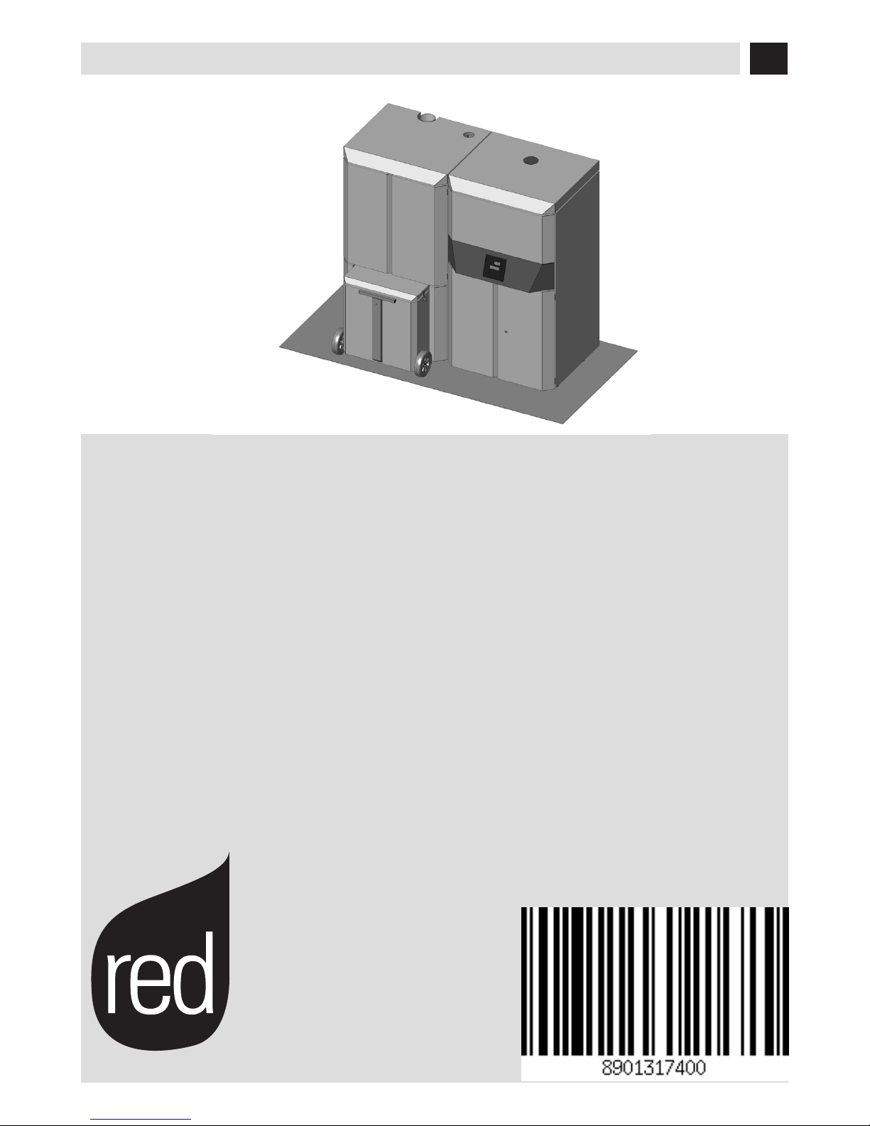
PELLET BOILER
LOGIKA 25-35
LOGIKA 25-35 REFILL
PART 1 - ASSEMBLY
Page 2

IIII
TABLE OF CONTENTS
TABLE OF CONTENTS ...................................................................................... II
INTRODUCTION ............................................................................................. 1
1WARNINGS AND WARRANTY CONDITIONS ...................................................... 2
2INSTALLATION INSTRUCTIONS ..................................................................... 7
3DRAWINGS AND TECHNICAL CHARACTERISTICS .............................................18
4 UNPACKING ............................................................................................22
5 POSITIONING ..........................................................................................26
6 INSTALLATION AND ASSEMBLY OF BOILER ...................................................28
7 INSTALLATION AND ASSEMBLY OF TANK ......................................................49
8 ASSEMBLY OF BOILER AESTHETICS UNIT .....................................................60
9 ASSEMBLY OF TROLLEY .............................................................................65
10 ASSEMBLY OF AESTHETICS UNIT OF REFILL TANK ........................................67
11 ASSEMBLY OF AESTHETICS UNIT OF MANUAL TANK .....................................73
Page 3

11
INTRODUCTION
Technical Dept. - All rights reserved - Reproduction is prohibited
Dear Customer,
Our boilers are designed and built in compliance with the European standard EN 303-5 (manual or automatic loading solid fuel
boilers). They also meet the essential requirements of directive 2006/95/EC (Low Voltage) and directive 2004/108/EC (Electromagnetic
Compatibility).
To get the best performance out of your boiler, we suggest you read the instructions in this manual carefully before
starting it up for the rst time.
This installation and use manual forms an integral part of the product: ensure that the manual is always supplied with the device, even if
the boiler changes owner. If the manual is lost, you can request another copy from the local technical service or download it directly from
the company website.
All local regulations, including those regarding national and European regulations, must be respected when the device is installed.
In Italy, for the installation of devices with biomass lower than 35KW, refer to ministerial decree 37/08, and the qualied installation
technician with the appropriate requisites must issue a certicate of compliance for the system installed.
REVISIONS TO THE PUBLICATION
The content of this manual is strictly technical and the property of MCZ Group Spa.
No part of this manual may be translated into other languages, adapted or reproduced, even in part, in other mechanical or electronic
forms, photocopies, recordings or other, without the prior written authorisation from MCZ Group Spa.
The company reserves the right to make changes to the product at any time without prior notice. The proprietary company reserves its
rights according to the law.
CARE OF THE MANUAL AND HOW TO CONSULT IT
• Take care of this manual and keep it in an easily accessible place.
• Should the manual be misplaced or ruined, request a copy from your retailer or directly from the authorised Technical Assistance
Department. It can be downloaded from the company website.
• The “text in bold” must be read with particular care.
• The “text in italics” draws attention to other sections in this manual or clarications.
• “NOTE” provides the reader with additional information.
SYMBOLS USED IN THE MANUAL
ATTENTION:
Read the relative message with care as failure to observe the information provided could result in
serious damage to the product and put the persons who use it at risk.
INFORMATION:
failure to comply with these provisions will compromise the use of the product.
OPERATING SEQUENCES:
sequence of buttons to be pressed to access the menus or change settings.
MANUAL
carefully read this manual or the relative instructions.
Page 4

22
1-WARNINGS AND WARRANTY CONDITIONS
SAFETY PRECAUTIONS
• Installation, electrical connection, function test and maintenance must only be carried out by authorised and
qualied personnel.
• Install the product in accordance with all local and national legislation and regulations in force in the region or state.
• Only use the fuel recommended by the manufacturer. The product must not be used as an incinerator. It is strictly forbidden to use
liquid fuel.
• Do not put any fuel other than wood pellets in the hopper.
• The instructions provided in this manual must always be complied with to ensure the product and any electronic appliances
connected to it are used correctly and accidents are prevented.
• The user, or whoever is operating the product, must read and fully understand the contents of this installation guide before
performing any operation. Errors or incorrect settings can cause hazardous conditions and/or poor operation.
• Do not climb on or lean on the product.
• Do not put linen on the product to dry. Any drying racks or similar objects must be kept at a safe distance from the product. Fire
hazard.
• All liability for improper use of the product is entirely borne by the user and relieves the Manufacturer from any civil and criminal liability.
• Any type of tampering or unauthorised replacement with non-original spare parts could be hazardous for the operator’s safety and
relieves the company from any civil and criminal liability.
• Many of the surfaces of the product get very hot (door, handle, glass, smoke extraction pipes, etc.). Therefore, avoid touching
these parts without wearing suitable protective clothing, such as heatproof gloves.
• It is forbidden to use the product with its door open.
• The product must be powered by an electrical system that is equipped with an eective earthing device.
• Switch the product o in the event of a fault or malfunction.
• Do not wash the product with water. The water could get inside the unit and damage the electrical insulation and cause electric
shocks.
• Install the product in a location that does not present a re hazard and is equipped with power and air supplies and smoke extractors.
• In the event of re in the chimney, turn o the device, disconnect it from the mains electricity and do not open the hatch. Then
contact the competent authorities.
• In the event of a malfunction with the ignition system, do not force it to light by using ammable materials.
• Special maintenance must only be performed by authorised and qualied personnel.
• Evaluate the static conditions of the surface on which the weight of the product will stand and provide suitable insulation if it is
made of a ammable material.
Page 5

33
1-WARNINGS AND WARRANTY CONDITIONS
Technical Dept. - All rights reserved - Reproduction is prohibited
INFORMATION:
Please contact the retailer or qualied personnel authorised by the company to resolve a problem.
• You must only use the fuel specied by the manufacturer.
• Check and clean the smoke extraction pipes regularly (connection to the chimney).
• Always keep the cover of the fuel hopper closed.
• Store this installation and use manual with care as it must accompany the product for the duration of its useful life. If the product is
sold or transferred to another user, ensure the manual is also handed over.
INTENDED USE
The product only works with wood pellets and must be installed indoors.
WARRANTY CONDITIONS
The company guarantees the product, with the exception of elements subject to normal wear listed below, for a period of 2 (two)
years from the date of purchase attested by:
• a document to serve as proof of purchase (invoice and/or receipt) that shows the name of the vendor and the date on which the
purchase was made;
• forwarding of the completed certicate of guarantee within 8 days of purchase.
Furthermore, in order for the guarantee to be valid, the device must be installed and calibrated by qualied personnel, and where
necessary, the user must be issued with a declaration of conformity and correct functioning of the product.
We suggest performing the product function test before completing the ner calibrations.
Any installation that fails to comply with the regulations in force will invalidate the product guarantee, as will improper use or failure to
carry out the maintenance prescribed by the manufacturer.
The guarantee is valid on the condition that the instructions and warnings contained in the use and maintenance manual are observed,
and therefore the product is used correctly.
The replacement of the entire system or the repair of one of its components does not extend the guarantee period, and the original expiry
date remains unchanged.
The guarantee covers the replacement or free repair of parts recognised as being faulty at source due to manufacturing defects.
To benet from the guarantee, in the event of a fault, the customer must have the guarantee certicate and present it with the proof of
purchase document to the Technical Assistance Oce.
Page 6

44
1-WARNINGS AND WARRANTY CONDITIONS
EXCLUSIONS
The guarantee does not cover malfunctions and/or damage to the appliance that arise due to the following causes:
• Damage caused during transportation or relocation
• all parts that develop faults due to negligence or improper use, incorrect maintenance, installation that does not comply with the
manufacturer’s instructions (always refer to the installation and use manual provided with the appliance)
• incorrect dimensioning with regards to the use or faults in the installation or failure to adopt the necessary devices to guarantee
proper execution
• improper overheating of the equipment, use of fuels not conforming to the types and quantities indicated in the instructions provided
• further damage caused by incorrect user interventions in an attempt to x the initial fault
• worsening of the damage caused by the user continuing to operate the appliance even after the fault has been noticed
• any corrosion, incrustation or cracking caused by water ow, condensation, hardness or acidity of the water, improper de-scaling
treatments, lack of water, mud or limescale deposits
• ineciency of chimneys, ues or parts of the system aecting the appliance
• damage caused by tampering with the appliance, atmospheric agents, natural disasters, vandalism, electrical discharges, res.
• faults in the electric and/or hydraulic system.
Also excluded from this guarantee are:
• parts subject to normal wear such as seals, glass, claddings and cast iron grids, painted parts, handles and electric cables, bulbs,
indicator lights, knobs, all removable parts from the rebox.
• Chrome variations of painted parts.
• masonry work
• parts of the system not supplied by the manufacturer
Any technical interventions on the product to eliminate the defects mentioned above and consequent damages must be agreed upon with
the Technical Assistance Centre, who reserves the right to accept the relative appointment or not. However, said interventions will not be
carried out under the guarantee but as technical assistance to be granted as part of any eventual and specic agreed conditions and in
accordance with the fee applicable for the work to be carried out.
The user will also be charged for any costs incurred to remedy the incorrect technical interventions, tampering or damage to the appliance,
not attributable to original faults.
Save for the legal or regulatory limits, the guarantee does not cover the containment of atmospheric and acoustic pollution.
The company declines all liability for any damage which may be caused, directly or indirectly, to persons, animals or objects as
a consequence of non compliance with any prescription specied in the manual, especially warnings regarding installation,
use and maintenance of the appliance.
Page 7
55
1-WARNINGS AND WARRANTY CONDITIONS
Technical Dept. - All rights reserved - Reproduction is prohibited
SPARE PARTS
In the event of a malfunction, consult the retailer who will forward the call to the Technical Assistance Service.
Use only original spare parts. The retailer or service centre can provide all necessary information regarding spare parts.
We do not recommend waiting for the parts to be worn before having them replaced. It is important to perform regular maintenance.
The company declines all liability if the product and any other accessory is used improperly or modied without
authorisation.
All parts must be replaced with original spare parts.
PRECAUTIONS FOR CORRECT DISPOSAL OF THE PRODUCT IN ACCORDANCE WITH THE EUROPEAN DIRECTIVE
2002/96/EC AND ITS SUBSEQUENT AMENDMENT 2003/108 EC.
At the end of its working life, the product must not be disposed of as urban waste.
It must be taken to a special dierentiated waste collection centre set up by the local authorities or to a retailer that provides this service.
Disposing of the product separately prevents possible negative consequences for the environment and health deriving from inappropriate
disposal and allows its materials to be recovered in order to obtain signicant savings in energy and resources.
As a reminder of the need to dispose of appliances separately, the product is marked with a crossed-out wheeled dustbin.
Page 8

66
1-WARNINGS AND WARRANTY CONDITIONS
RULES FOR INSTALLATION
The product is a boiler that uses wood pellets.
Below is a list of European regulations regarding the installation of the product:
EN 303-5:2012: Solid fuel boilers, with manual or automatic loading, nominal thermal power of 500 kW - Terminology, requisites, tests
and marking.
EN 12828 Heating systems design.
Electrical systems with rated voltage not exceeding 1000 V AC and 1500 V DC.
EN 1443 General chimney regulation
EN 1856-1 metal smoke ducts
EN 1856-2 metal smoke extraction channels
EN 1457 chimneys - Interior terracotta / ceramic ues
EN 13384-1 Chimneys - Thermal and dynamic uid calculation methods - Part 1: Chimneys connected to a single appliance
Below are some applicable regulations for Italy:
UNI 10683:2012 Heat generators fuelled by wood or other solid bio-fuels - Test, installation, control and maintenance (for thermochemical
power at the rebox lower than 35kW)
UNI/TS 11278 general technical regulation for the choice of smoke duct/ue
UNI 10847:2000 Smoke extractor systems for liquid and solid fuelled generators - Maintenance and control - Guidelines and procedures
UNI 8065 water treatment in civil plants.
UNI 9182 Hot and cold (sanitary) air supply and distribution systems.
Installation must be carried out with reference to the diagram of the heating system prepared in accordance with the
standards and local recommendations in force:
In any case, respect:
For the heating appliance
Local requirements concerning the chimney connection.
Local requirements for re-ghting standards.
For electrical parts - EN 60335 ‘’Safety of electrical household appliances and similar
Part 1 - General requirements
Part 2 - Special regulations for appliances with gas, gas oil and solid fuel burners with electrical connections.
Page 9
77
2-INSTALLATION INSTRUCTIONS
Technical Dept. - All rights reserved - Reproduction is prohibited
The instructions in this chapter refer explicitly to the Italian installation regulation UNI 10683. In any case, always observe the domestic
regulations in force.
PELLETS
Wood pellets are manufactured by hot-extruding compressed sawdust which is produced during the working of natural dried wood. The
compactness of the material is guaranteed by the lignin contained in the wood itself and allows pellets to be produced without glue or
binders.
The market oers dierent types of pellets with characteristics that vary according to the wood mixtures used. The diameter varies
between 6 and 8 mm, with a standard length ranging from 5 to 30 mm. A good quality pellet has a density of between 600 and 750 or
more kg/metres cubed and a water content that accounts for 5 to 8% of its weight.
Pellets have technical advantages besides being an ecological fuel, as the wood residue is used completely, thereby achieving cleaner
combustion than that of fossil fuels.
Good-quality wood has a caloric value of 4.4 kW/kg (15% moisture, after about 18 months of seasoning), whereas that of pellets is 4.9
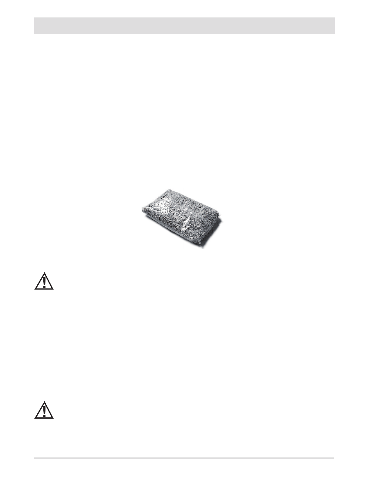
kW/kg. To ensure good combustion, the pellets must be stored in a dry place and protected from dirt. Pellets are usually supplied in 15 kg
bags, therefore, storing them is very convenient.
Good quality pellets guarantee good combustion, thereby decreasing harmful emissions into the atmosphere.
The poorer the quality of the fuel, the more often the internal parts of the brazier and combustion chamber must
be cleaned.
The main quality certications for pellets currently available on the European market guarantee that the fuel complies with class A1/A2
according to EN14961-2. These certications include, for example, ENPlus, DINplus, Ö-Norm M7135, and in particular, guarantee the
following characteristics:
• caloric value: 4.6 ÷ 5.3 kWh/kg.
• Water content: max 10% of the weight.
• Percentage of ash: max 1.5% of the weight.
• Diameter: 5 ÷ 6 mm.
• Length: max 40 mm.
• Content: 100% untreated wood without the addition of binding substances (max 5% bark).
• Packaging: in sacks made from ecologically compatible or biologically decomposing material.
The company strongly recommends using certied fuel for its products (ENplus, DINplus, Ö-Norm M7135).
Poor quality pellets or others that do not comply with the characteristics specied previously may compromise the
operation of your product and can therefore render the guarantee and product liability invalid.
15 Kg BAGS OF FUEL
Page 10
88
2-INSTALLATION INSTRUCTIONS
PRECAUTIONS REGARDING INSTALLATION
IMPORTANT!
Product installation and assembly must be carried out by qualied personnel.
The product must be installed in a suitable place that allows easy access for it to be opened regularly and for routine maintenance to be
performed.
The installation area must be:
• suitable to enable the appliance to operate correctly.
• Equipped with an adequate smoke extraction system.
• Equipped with adequate ventilation from outside.
• Equipped with 230V 50 Hz power supply with an EC compliant earthing system.
IMPORTANT!
The product must be connected to a chimney that expels the smoke at the highest point of the building.
The chimney must be of suitable dimensions, caulked, and tted with a condensation collector for collecting the
water vapour that can form due to the high performance of the appliance and the consequently low temperatures
of the outgoing fumes.
The chimney must comply with regulations in force.
The holes of the external air inlet and the smoke outlet pipe must be drilled before positioning the product.
THE OPERATING AREA
The boiler must be installed indoors in an area well protected from atmospheric elements.
The surface on which it stands and/or support points must have sucient load bearing capacity to support the total weight of the
appliance, its accessories and covers.
To ensure the appliance works well, we recommend installing the boiler detached from any walls or furniture, and with good air circulation
to allow eective ventilation for the appliance. The product should be located in an area that allows sucient space for normal use and
maintenance operations.
The volume of the room should be no less than 15 m3.
It is essential that an adequate outdoor air intake is provided that supplies the air for combustion needed for the product to function
correctly.
These air inlets must be arranged so that it is impossible for them to be obstructed.
Protect the inlets with grilles, metal mesh, etc., without reducing the net cross-section.
Remember that the ventilation grilles always have the useful cross-section in cm2 indicated on one side. When
choosing the grille and size of the inlet, check that the useful cross-section of the grille is larger or equal to the
section required for product operation.
The ow of air between the outside and the room of installation may be direct, through an inlet in an external wall of the building; or
indirect, through the intake of air from rooms adjoining and connecting permanently with the room of installation. Adjoining areas may
not include sleeping areas, garages or general areas that present a re hazard.
For air ducts, up to 3m increase the cross-section by approximately 5%, while for ducts that run for longer increase it by 15%.
IMPORTANT!
The air ow can also be drawn from an adjoining room to that of the room where the product is installed, provided
the air can ow freely through permanent openings to the outside; avoid connection to sleeping areas and rooms
that present a re hazard in general.
Page 11
99
2-INSTALLATION INSTRUCTIONS
Technical Dept. - All rights reserved - Reproduction is prohibited
POSITIONING AND RESTRICTIONS
In the case of simultaneous installation with other heating appliances, provide appropriate air inlets for each one (according to the
instructions of each product).
Installation of the product is not permitted:
• in rooms where there are liquid fuel appliances with continuous or intermittent operation that draw the
combustion air from the room they are installed in;
• in rooms where there are B-type gas heating appliances, with or without domestic hot water production and
interconnecting rooms;
• in rooms in which the decrease in pressure during use, as measured between the pressure outside and the
pressure in the room, is greater than 4 Pa.
The product may not be installed in rooms used as sleeping areas, bathrooms, garages or in rooms that present a
re hazard in general.
BOILER ROOM
Check that the room meets the requirements and provisions of the standards in force. There must also be a ow of at least enough air in
the room for normal combustion. Vents must be installed in the walls of the room that meet the following requirements:
• Increase the cross-section by at least 6 cm2 for each 1 kW (859.64kcal/h) The minimum cross-section of the opening must not,
however, measure less than 100 cm. The cross-section can be calculated using the following relations:
S = K * Q ≥ 100 cm
2
Where “S” is in cm2, “Q” in kW, “K” = 6 cm2/kW
• The opening must be located at the base of an external wall, preferably opposite the one with the outlet for combusted gases.
Heat-sensitive or ammable objects cannot be stored near the product; keep such objects at a minimum distance of
80 cm from the outermost point of the product.
CONNECTION OF THE SMOKE EXHAUST DUCT
When making the hole for the passage of the smoke discharge pipe, it is necessary to take into account the possible presence of ammable
materials. If the hole has to be in a wall made of wood or other thermolabile material, THE INSTALLER MUST rst set up the relative wall
tting (diameter 13 cm minimum) and insulate the pipe of the product passes with appropriate insulating material (1.3 - 5 cm thick with
minimum heat conductivity of 0.07 W/m°K).
The same minimum distance must be applied if the pipe of the product must pass through vertical or horizontal sections near the
thermolabile wall.
It is recommended to use an insulated double-wall pipe in external sections in order to prevent condensation from forming.
The combustion chamber works in negative pressure.
Page 12
10
min.3,5 metri
AT
(A)
AP
(B)
10
2-INSTALLATION INSTRUCTIONS
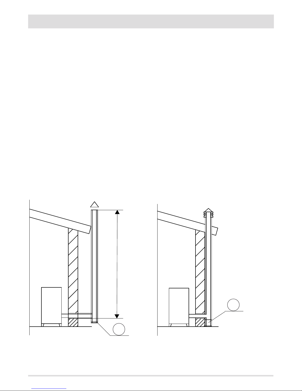
FOREWORD
This chapter on the Smoke Flue has been produced in reference to the prescriptions of European regulations (EN13384 - EN1443 - EN1856
- EN1457).
The chapter provides indications for installing an ecient and correct smoke ue but is under no circumstances to substitute the
regulations in force, which the qualied technician must be in possession of. Check with local authorities whether there are any restrictive
regulations in force regarding the intake of air for combustion, the smoke extraction system, the ue or the chimney.
The company declines all liability relating to the poor functioning of the boiler if this is due to the use of an insuciently sized ue in
violation of regulations in force.
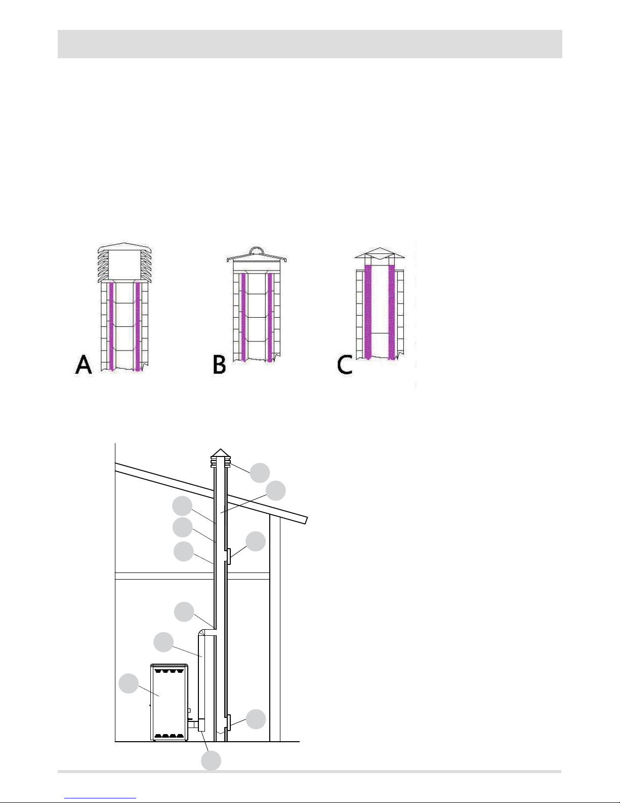
SMOKE FLUE
Have the eciency of the ue checked by an authorised technician.
The ue or chimney is vital to the correct functioning of a forced draft solid fuel heating appliance, given that boilers with high performance
have cooler fumes with consequently weaker draft and the possible formation of condensation.
It is therefore essential that the ue meets all construction standards and is always maintained in perfect condition.
A ue that serves a pellet/wood fuelled appliance must be at least category T400 (or greater if the appliance requires, and resistant to soot
res. Smoke must be extracted through a single ue made of insulated steel (A) or an existing ue that complies with the intended use (B).
A simple air shaft in cement must be suitably lined. In either case, ensure to include an inspection cap (AT) or inspection door (AP) and a
suitable device for collecting condensation - FIG.1.
It is prohibited to connect more than one wood/pellet or any other type of appliance (vent cowling...) to the same ue.
15 Kg BAGS OF FUEL
Page 13
11
A
B
C
D
E
A
B
C
D
15°
E
F
11
2-INSTALLATION INSTRUCTIONS
Technical Dept. - All rights reserved - Reproduction is prohibited
TECHNICAL CHARACTERISTICS
Flues serving a pellet/wood fuelled appliance must meet the following requirements:
• made of materials that are suciently resistant to mechanical stress, heat, the action of the products of combustion and their
vapours.
• made of materials that are impermeable to fumes, condensation, be thermally insulated and resistant to normal mechanical stress
over time
• go in a vertical direction and deviate no more than 45° from the vertical axis and be free of choke points
• be suited to the specic operating conditions of the product and have CE marking (EN1856-1, EN1443).
• Be of the correct size to suit the draft/smoke extraction requirements necessary for the product to work properly (EN13384-1)
• Be suitably caulked externally to avoid condensation and reduce the cooling of the smoke.
• Be at least category T400 (or greater if the appliance requires) and resistant to soot res.
We recommend in particular to check on the data tags of the ue (in accordance with EN1856-1, EN1443) the safety distances that must
be respected in presence of passing combustible materials and the type of insulating material to be used. These indications must be
followed rigorously to avoid serious harm to personnel and surrounding infrastructure.
The chimney opening must be in the same room as the appliance, or at most in the adjoining room, and have a soot and condensation
collection chamber beneath the opening, and be accessible via a watertight metal hatch.
Smoke must be extracted through a single ue (see g. 3) with insulated steel tubes (A) or though an existing ue that complies with
the intended use (B). A simple air shaft in cement must be suitably lined. In either case, ensure to include an inspection cap (AT) and/or
inspection door (AP) and a suitable device for collecting condensation - FIG.1.
It is prohibited to connect more than one wood/pellet or any other type of appliance (vent cowling...) to the same ue.
FLAT ROOF
ROOF AT 15°
A = 0.50 metres
B = DISTANCE > 2 metres
C = DISTANCE < 2 metres
D = O.50 metres
E = TECHNICAL VOLUME
A = MIN. 1.00 metres
B = DISTANCE > 1.85 metres
C = DISTANCE < 1.85 metres
D = 0.50 metres above highest
point
E = 0.50 metres
F = REFLUX ZONE
FIGURE 2
FIGURE 3
Page 14
12
A
B
C
D
E
30°
F
A
B
D
60°
E
C
F
A
B
C
D
E
45°
F
12
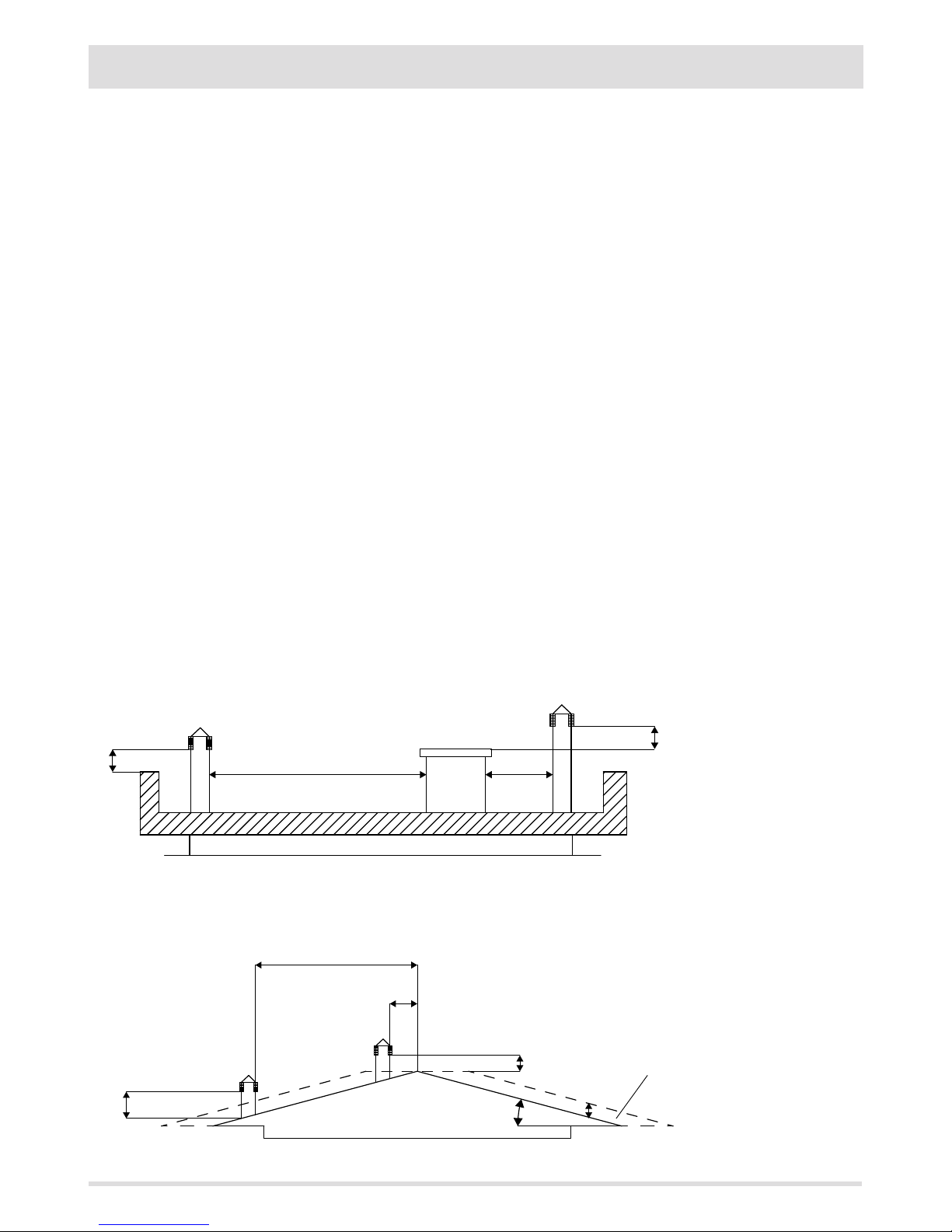
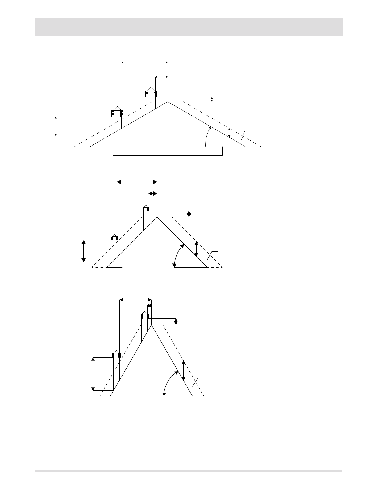
2-INSTALLATION INSTRUCTIONS
ROOF AT 30°
ROOF AT 60°
ROOF AT 45°
A = MIN. 1.30 metres
B = DISTANCE > 1.50 metres
C = DISTANCE < 1.50 metres
D = 0.50 metres ABOVE
HIGHEST POINT
E = 0.80 metres
F = REFLUX ZONE
FIGURE 4
A = MIN. 2.60 metres
B = DISTANCE > 1.20 metres
C = DISTANCE < 1.20 metres
D = 0.50 metres ABOVE
HIGHEST POINT
E = 2.10 metres
F = REFLUX ZONE
FIGURE 6
A = MIN. 2.00 metres
B = DISTANCE > 1.30 metres
C = DISTANCE < 1.30 metres
D = 0.50 metres ABOVE
HIGHEST POINT
E = 1.50 metres
F = REFLUX ZONE
FIGURE 5
Page 15
13
13
2-INSTALLATION INSTRUCTIONS
Technical Dept. - All rights reserved - Reproduction is prohibited
DIMENSIONING
The drop in pressure (draft) of a ue depends on its height. Check the drop in pressure with the values indicated in the technical
characteristics. The minimum height of the chimney is 3.5 meters.
The interior cross-section of the ue can be circular (best variation), square or rectangular (the ratio between the interior sides must be
≤1.5) with the sides joined with a minimum radius of 20 mm. The dimension of the cross-section must be a minimum Ø150mm.
The cross-sections/lengths of the chimneys shown in the technical data tables are indications for correct installation. Any alternative
congurations must be correctly dimensioned in accordance with the general method of calculation of UNI EN13384-1 or other proven
eciency methods.
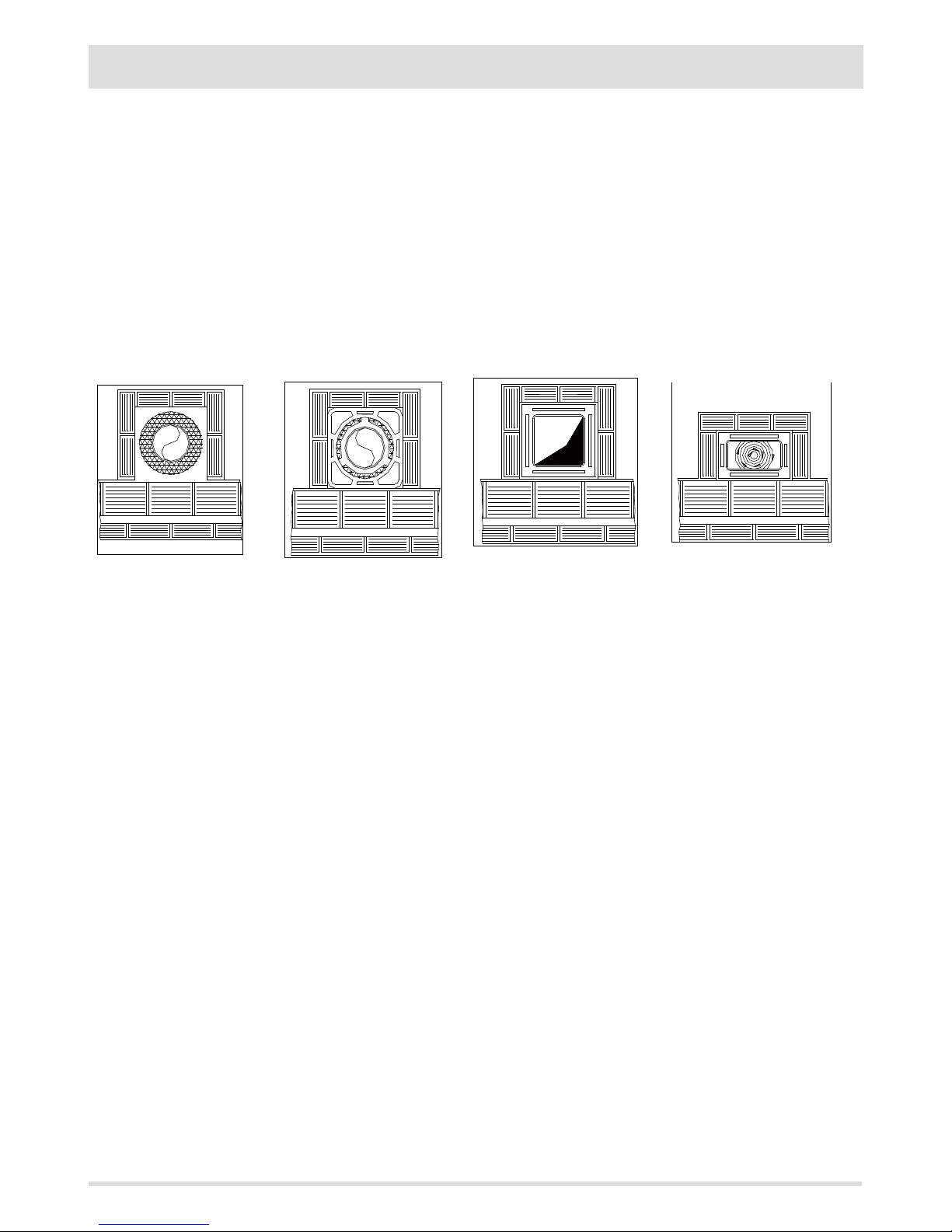
Below is a list of some ues available on the market:
Steel chimney AISI 316 with
double chamber insulated with
ceramic bre or equivalent
resistant up to 400°C.
Refractory chimney with
double insulated chamber and
external lightweight concrete
cladding with cellular material
such as clay.
Traditional square-section clay
chimney with insulating empty
inserts.
Avoid products with an internal
rectangular section where the
larger side is 1.5 times the
smaller side (e.g. 20x40 or
15x30).
EXCELLENT GOOD POOR VERY POOR
Page 16
14
1
9
9
2
3
4
5
6
7
8
9
14
2-INSTALLATION INSTRUCTIONS
MAINTENANCE
The ue must be kept clean, since the deposit of soot or unburned oils reduces the cross-section reducing the draft and thus compromising
the ecient functioning of the heater and, if large build-ups accumulate, can catch re. The ue and chimney must be cleaned and
checked by a qualied chimney sweep at least once a year. Once the maintenance has been performed, request a written declaration that
the device is safe.
Failure to clean the system jeopardises the safety.
CHIMNEY
The chimney is a crucial element for the heating appliance to work properly: we recommend a wind proof chimney (A), see Figure 7.
The area of the opening for smoke extraction must be at least double the cross-section of the smoke duct/ue system, and arranged so
that smoke extraction is ensured even
in strong wind. The chimney must
prevent rain, snow or animals from
entering the chimney. The height of
outow into the atmosphere must be
beyond the reux zone created by the
shape of the roof or any obstacles near
the outlet (see Figures 2-3-4-5-6).
CHIMNEY COMPONENTS
KE Y:
(1) CHIMNEY
(2) REFLUX CHANNEL
(3) SMOKE DUCT
(4) THERMAL INSULATION
(5) OUTSIDE WALL
(6) CHIMNEY CONNECTION
(7) SMOKE CHANNEL
(8) HEAT GENERATOR
(9) INSPECTION ACCESS PANEL
FIGURE 7
FIGURE 8
Page 17
1515
2-INSTALLATION INSTRUCTIONS
Technical Dept. - All rights reserved - Reproduction is prohibited
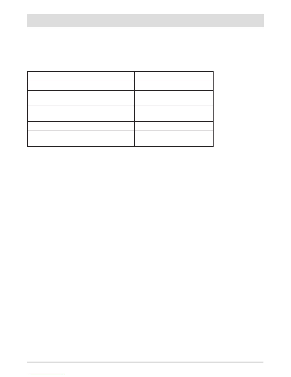
CONNECTION TO FLUE
The connection between the ue and the appliance must be via a smoke duct that conforms with EN 1856-2. The connecting section
must extend no more than 4 m horizontally, with a maximum incline of 3% and containing a maximum of 3 90% bends (accessible for
inspection - do not count the T joint at the appliance outlet).
The diameter of the smoke duct must be equal to or greater than that of the outlet of the appliance (Ø 100 mm).
TYPE OF DEVICE SMOKE DUCT
Minimum vertical length 1.5 metres
Maximum length
(with 1 accessible 90° bend)
6.5 metres
Maximum length
(with 3 accessible 90° bends)
4.5 metres
Maximum number of accessible 90° bends 3
Horizontal sections
(minimum incline 3%)
4 metres
Use smoke ues of 100mm diameter and silicon seals or similar seals that can resist the high operating temperatures of the appliance
(min. T200 class P1). The use of exible metal tubes in bre cement or aluminium is prohibited. For direction changes, we
always recommend the use of a T joint with an inspection cap allowing easy access for cleaning the tubes. Always ensure that the
inspection cap is replaced and hermetically sealed with the seal in tact after cleaning.
It is prohibited to connect more than one appliance to the same smoke duct, or the discharge from overhead cowling. It is prohibited to
extract the products of combustion directly through the wall, whether into indoor spaces or outdoors.
The smoke duct must be a minimum distance of 400 mm from ammable or heat-sensitive structures.
Page 18
16
T
I
S
I
U
B
A
P
U
I
I
C
4
3
D
2
I
E
V
U
1
F
16
2-INSTALLATION INSTRUCTIONS
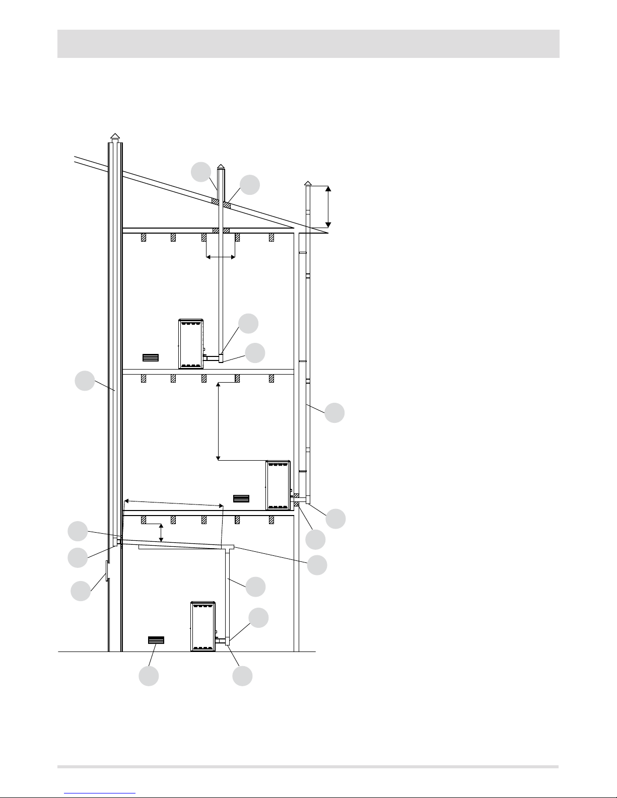
EXAMPLES OF CORRECT INSTALLATION
1. Installation of Ø150mm ue with hole for the passage
of the tube increased by:
minimum 100 mm around the tube if next to non
ammable parts such as cement, brick, etc.; or
minimum 300 mm around the tube (or as prescribed by
data tags) if next to ammable parts such as wood etc.
In both cases, install suitable insulation between the ue
and the ceiling.
Always check and respect the data tags on the ue,
in particular the minimum safety distances from
combustible materials.
The previous rules also apply for holes made in walls.
2. Old ue, minimum tube Ø150mm with the inclusion
of an external access door for chimney cleaning.
3. External ue made of insulated stainless steel tubes,
i.e. with double walls minimum Ø150mm: all securely
mounted to the wall. With wind-proof chimney. See g.
7 type A.
4. Ducting system using T joints that allow easy access
for cleaning without having to remove the tubes
FIGURE 11
U = INSULATING
V = ANY REDUCTION FROM 100 TO 80 MM
I = INSPECTION CAP
S = INSPECTION ACCESS PANEL
P = AIR INLET
T = T JOINT WITH INSPECTION CAP
A = MINIMUM 40 MM
B = MAXIMUM 4 M
C = MINIMUM 3°
D = MINIMUM 400 MM
E = HOLE DIAMETER
F = SEE FIG.23456
Page 19
1717
2-INSTALLATION INSTRUCTIONS
Technical Dept. - All rights reserved - Reproduction is prohibited
CONNECTION OF THE SMOKE EXHAUST DUCT
When making the hole for the passage of the smoke discharge pipe, it is necessary to take into account the possible presence of ammable
materials. If the hole has to be in a wall made of wood or other thermolabile material, THE INSTALLER MUST rst set up the relative wall
tting (diameter 13 cm minimum) and insulate the pipe of the product passes with appropriate insulating material (1.3 - 5 cm thick with
minimum heat conductivity of 0.07 W/m°K).
The same minimum distance must be applied if the pipe of the product must pass through vertical or horizontal sections near the
thermolabile wall.
It is recommended to use an insulated double-wall pipe in external sections in order to prevent condensation from forming.
The combustion chamber works in negative pressure.
Page 20
18
1540
1385
815
1950
MIN.1700
100
1200
650 100
30
1060
18
3-DRAWINGS AND TECHNICAL CHARACTERISTICS
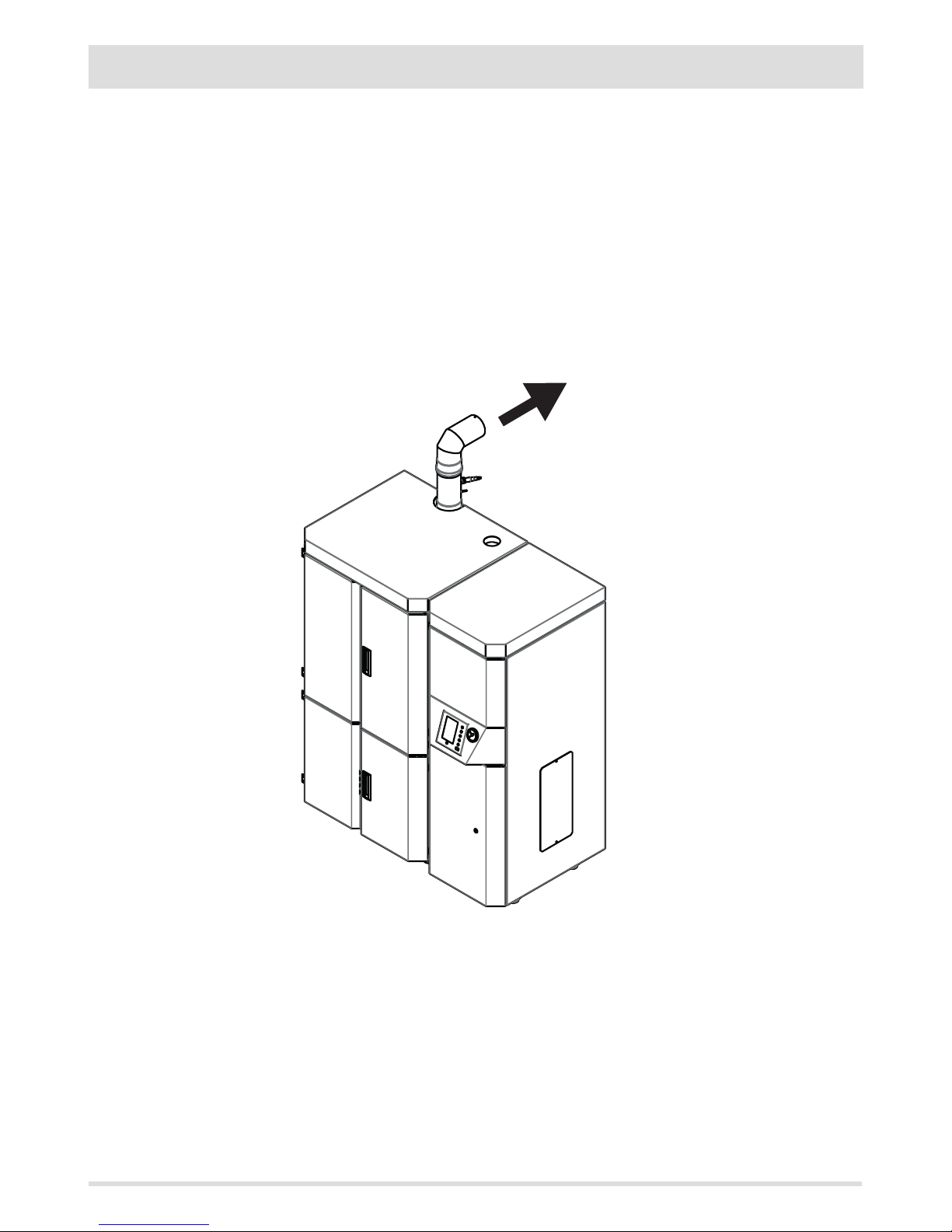
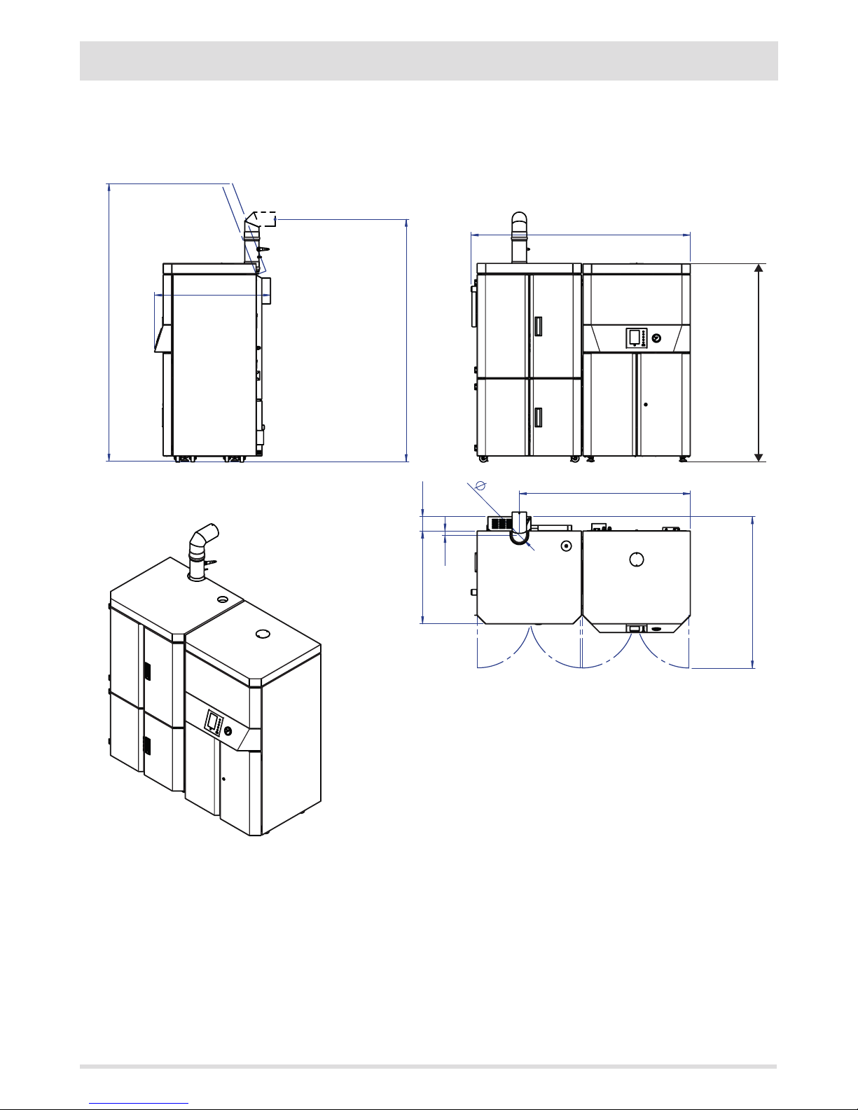
DRAWINGS AND CHARACTERISTICS
DIMENSIONS OF LOGIKA 25-35 HYDRO (dimensions in mm)
N.B. The 90° bend is not provided with the boiler.
Page 21
19
1235
1385
815
1950
MIN.1700
100
900
650 100
30
1100
19
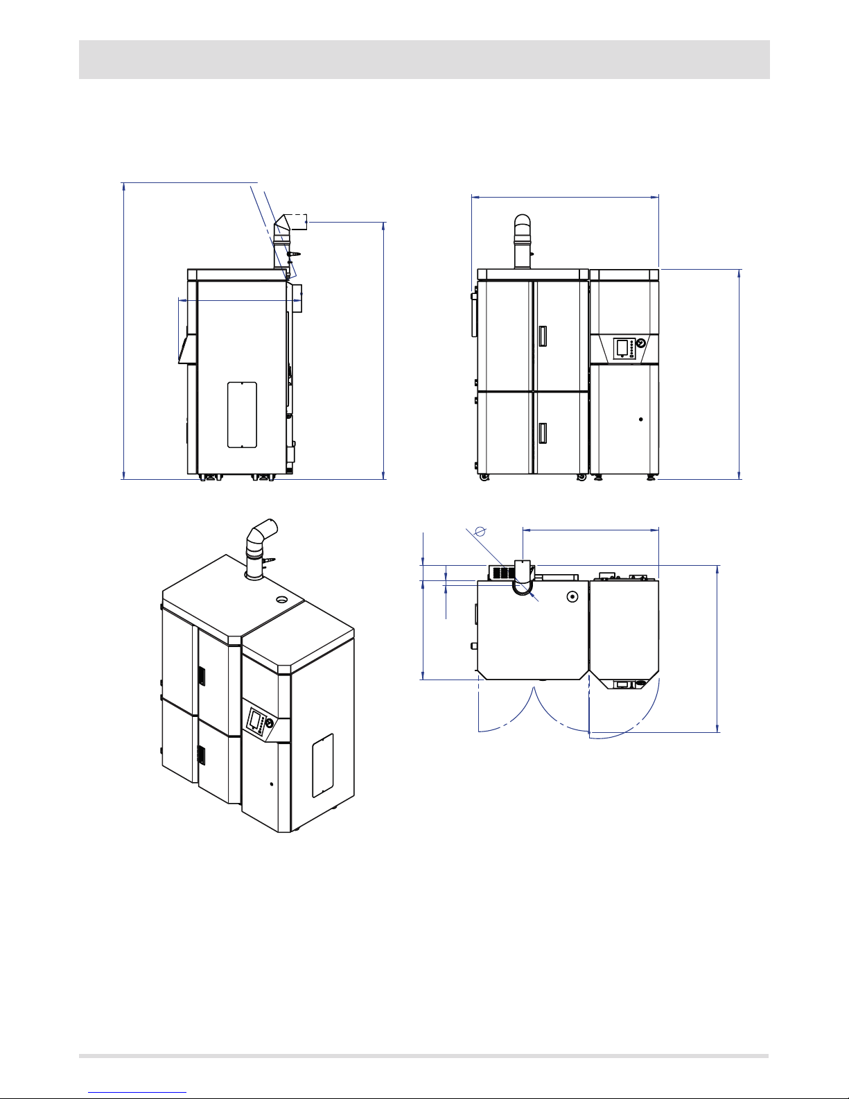
3-DRAWINGS AND TECHNICAL CHARACTERISTICS
Technical Dept. - All rights reserved - Reproduction is prohibited
DIMENSIONS OF LOGIKA 25-35 REFILL HYDRO (dimensions in mm)
N.B. The 90° bend is not provided with the boiler.
Page 22

2020
3-DRAWINGS AND TECHNICAL CHARACTERISTICS
TECHNICAL CHARACTERISTICS LOGIKA 25 LOGIKA 35
Product class (EN 303-5/2012) 5 5
Rated thermal capacity of the rebox 25.8 kW (22188 kcal/h) 33.8 kW (29068 kcal/h)
Nominal output power: 24.8 kW (21328 kcal/h) 32.1 kW (27606 kcal/h)
Minimum output power 8.3 kW (7138 kcal/h) 8.3 kW (7138 kcal/h)
Eciency at Max 96.1% 95.0%
Eciency at Min 91.2% 91.2%
Temperature of exhaust smoke at Max 100°C 120°C
Temperature of exhaust smoke at Min 60°C 60°C
Max congurable temperature 80°C 80°C
Max operating temperature 95°C 95°C
Particles/OGC/Nox (10%O2) 39 mg/Nm3 - 1 mg/Nm3 - 250 mg/Nm
3
33 mg/Nm3 - 1 mg/Nm3 - 275 mg/Nm
3
CO at 10% O2 at Min and at Max 0.024 - 0.009% 0.024 - 0.006%
CO2 at Min and at Max 5.89 - 10.2% 5.8 - 10.38%
Recommended draught at Max power 0.10 mbar - 10 Pa 0.10 mbar - 10 Pa
Recommended draught at Min power 0.05 mbar - 5 Pa 0.05 mbar - 5 Pa
Smoke mass 16.4 g/sec 21.0 g/sec
Tank capacity 210 litres (manual feed tank) 210 litres (manual feed tank)
Type of pellet fuel Pellet diameter 6-8 mm and size 5/30 mm Pellet diameter 6-8 mm and size 5/30 mm
Pellet hourly consumption Min ~ 1.5 kg/h* - Max ~ 5.3 kg/h* Min ~ 1.5 kg/h* - Max ~ 7 kg/h*
Autonomy At min ~ 100 h* - At max ~ 29 h* At min ~ 100 h* - At max ~ 22 h*
Heatable volume m
3
518/40 - 592/35 - 691/30** 690/40 - 789/35 - 920/30**
Water content 90 litres 90 litres
Max operating temperature 3 bar - 300 kPa 3 bar - 300 kPa
Combustion air inlet 80 mm 80 mm
Smoke outlet 100 mm 100 mm
Air outlet 100 cm
2
100 cm
2
Rated electrical power (EN 60335-1) 180 W (Max 960 W) 180 W (Max 960 W)
Supply voltage and frequency 230 Volt / 50 Hz 230 Volt / 50 Hz
Net weight 705 kg (with tank) 705 kg (with tank)
Weight with packaging 725 kg 725 kg
* Data that may vary depending on the type of pellets used.
** Volume that can be heated, according to the power requirement in m3 (respectively 40-35-30 Kcal/h per m3)
Page 23
21
0
100
200
300
400
500
600
0 500 1000 1500 2000
A
B
21
3-DRAWINGS AND TECHNICAL CHARACTERISTICS
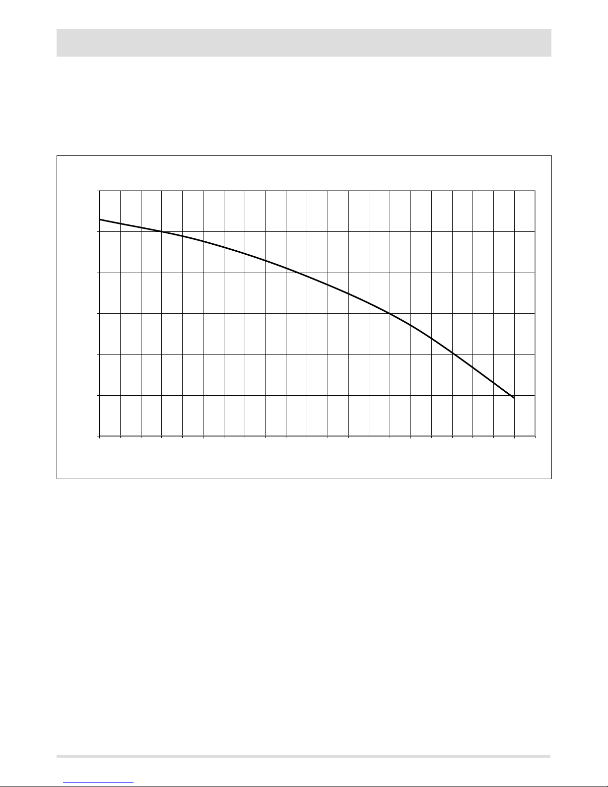
Technical Dept. - All rights reserved - Reproduction is prohibited
Residual head
We recommend in particular to check the data tags of the ue for the safety distances that must be respected in presence
of combustible materials and the type of insulating material to be used. These indications must be followed rigorously to
avoid serious harm to personnel and surrounding infrastructure.
A = Residual Head (mbar)
B = Load (l/h)
Page 24
22
CBA
E
D
F
22
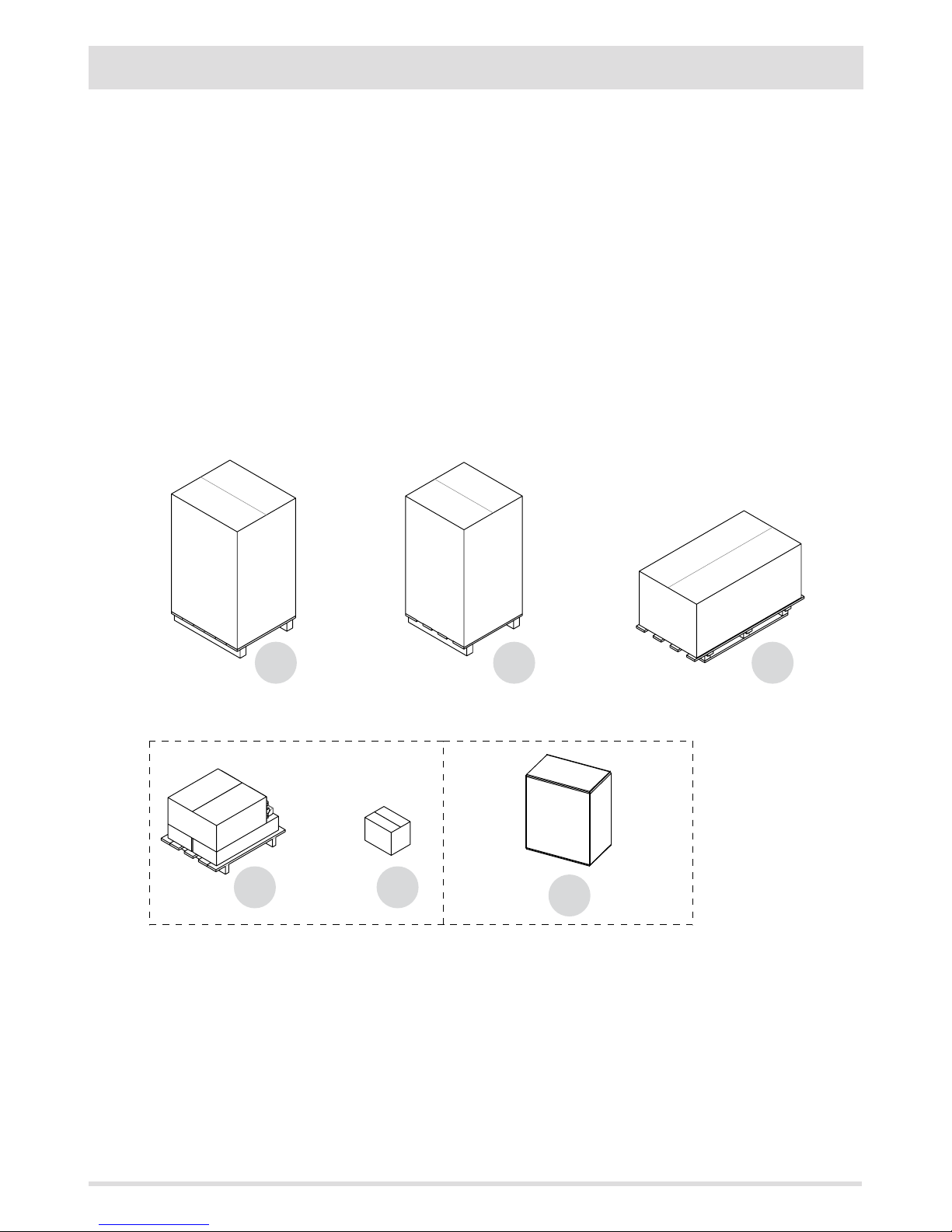
4 - UNPACKING
PREPARATION AND UNPACKING
The LOGIKA boiler is delivered inclusive of all if electrical and mechanical components and already tested at the factory:
Install the boiler in the area set aside for it, making sure it conforms to the requirements. The body of the boiler must only ever be carried
upright with a trolley. The product must always be moved with care. If possible, unwrap the boiler near the chosen place of installation.
The packaging materials are neither toxic nor harmful, and therefore no particular disposal measures are required.
After removing all the packaging, check that the boiler is complete and not damaged. If in doubt, contact the retailer.
PACKAGING OF THE LOGIKA 25/35 BOILER
The Logika boiler is delivered in three dierent packages (and with additional packages for accessories), depending on the model:
• A - structure of the boiler (1 pack)
• B - tank (1 pack)
• C - casing of the boiler/tank (1 pack)
Easyclean kit accessories (on request)
• D - automatic ash outlet (1 pack)
• E - automatic turbolator (1 pack)
Accessory kit circulator (optional)
F - standard or High Eciency circulator kit (1 package)
The following documents are provided in the package:
• Plant booklet
• Instruction booklet
• Annex G - Technical test report for thermal plant of less than 35 kW.
• Warranty
Page 25

23
k j
23
4 - UNPACKING
Technical Dept. - All rights reserved - Reproduction is prohibited
UNPACKING THE STRUCTURE OF THE BOILER
TOOLS: 10 mm face or box spanner
Open the package and remove the two front and back brackets, removing the two screws between each bracket and the boiler and the
two screws that fasten the bracket to the pallet.
Remove the rear bracket, undoing the screws “j” and taking o panel “k” to access the area more easily.
Put the panel “k” back in place when you have done.
FIGURE 1 - STRUCTURE OF LOGIKA 25-35 BOILER
REMOVAL SCREWS OF PACKAGE
FRONT VIEW
REAR VIEW
Page 26

2424
4 - UNPACKING
UNPACKING THE TANK
Open the package and remove the two screws between the bracket and the boiler and the two screws that fasten the bracket to the pallet.
UNPACKING THE COMPLETE CASING
The package of the casing contains the following material:
• BOILER AESTHETICS UNIT
COMPLETE RIGHT-HAND DOOR (1)
COMPLETE RH PANEL (6)
COMPLETE LEFT-HAND DOOR (2)
COMPLETE LEFT-HAND PANEL (5)
COMPLETE BOTTOM RIGHT-HAND DOOR (3)
COMPLETE LEFT-HAND DOOR (4)
COMPLETE TOP DOOR (COVER) (7)
• MANUAL TANK AESTHETICS UNIT
COMPLETE RIGHT-HAND PANEL (12)
COMPLETE LEFT-HAND PANEL (11)
COMPLETE LEFT-HAND DOOR (9)
COMPLETE RIGHT-HAND DOOR (8)
BOTTOM REAR PROTECTION (14)
FRONT PANEL (10)
• MANUAL LEVER FOR CLEANING TURBOLATORS
FIGURE 2 - LOGIKA 25-35 BOILER MANUAL TANK
REMOVAL SCREWS OF PACKAGE
FIGURE 2 - LOGIKA 25-35 BOILER REFILL TANK
REMOVAL SCREWS OF PACKAGE
Page 27

2525
4 - UNPACKING
Technical Dept. - All rights reserved - Reproduction is prohibited
EASYCLEAN KIT PACKAGE
AUTOMATIC TURBOLATOR KIT
ACTUATOR
FEEDER
PLASTIC CAP
AUTOMATIC ASH OUTLET KIT
• EASYCLEAN ASH OUTLET KIT
ASH DOOR SUPPORT 2 X PIECES (see piece “a” page 34)
MICROSWITCH SUPPORT BRACKET 1 X PIECE (see piece page 35)
CENTRAL DOOR SUPPORT 1 X PIECE (see piece “b” page 34)
LOCK CONNECTION 2 X PIECES (see piece “y”page 34)
AUGER ASSEMBLY KIT 2 X PIECES (see page 27)
ASH TRAY ASSEMBLY 2 X PIECES (see piece “c” page 34)
TROLLEY DRAWER ASSEMBLY 1 X PIECE (see page 63)
• BOLTS AND SCREWS KIT
Page 28

26
815
1950
MIN.300
MIN.1700
1063
MIN. 300
300
~400
1000
652
MIN.600
1385
815
1950
MIN.300
MIN.1700
1105
MIN. 300
300
~400
1000
652
MIN.600
1385
26
5 - POSITIONING
REQUIREMENTS FOR INSTALLATION OF THE PLANT - POSITIONING
The most important thing to do before installation of the LOGIKA boiler is to set aside a suitable area that meets the minimum requirements
for installation.
• the minimum clearance in front of the product for the purpose of cleaning, maintenance, etc. must be 1000 mm;
• the minimum permissible distance between the back of the product and a wall must be 400 mm;
• the minimum distance between the top of the product and the ceiling must be 600 mm to ensure easy access to the heat exchanger
for the purpose of cleaning and maintenance (e.g. for removing ash);
• the minimum clearance between the product and the wall (side) must be 300 mm.
MINIMUM REQUIREMENTS FOR LOGIKA BOILER AND MANUAL TANK MINIMUM REQUIREMENTS FOR LOGIKA BOILER AND REFILL TANK
Page 29

2727
5 - POSITIONING
Technical Dept. - All rights reserved - Reproduction is prohibited
FOOT ADJUSTMENT
In the lower part of the boiler and the tank, near the wheels, there are adjustable feet mounted (in the tank there are no wheels).
It is possible to unscrew the foot with a spanner to stabilise the structure.
1. TURN THE FEET CLOCKWISE TO LOWER THE PRODUCT.
2. TURN THE FEET ANTI-CLOCKWISE TO RAISE THE PRODUCT.
Page 30

2828
6 - INSTALLATION AND ASSEMBLY OF BOILER
Instructions on how to install the structure of the LOGIKA boiler:
a. Positioning on the ground (lifting or slide).
b. Put the tank and boiler in the room where they are to be installed (but NOT in their denitive position).
c. Check and install any additional kits (automatic turbolators/automatic ash outlet).
d. Assembly of the right-hand side of the boiler.
e. Denitive installation with reference to the diagram showing the minimum requirements.
f. Assemble probe pipe 100 at boiler outlet.
g. Assemble the lambda probe and connect it to the boiler connector.
h. Connect the pressure gauge pipe to the pressure outlet.
a) Positioning on the ground (lifting or slide).
After unpacking the structure it is possible to move the boiler in two ways:
1) using the lifting hook on the boiler and a hoister.
WEIGHT ABOUT 500 KG
Page 31

29
x
==
29
6 - INSTALLATION AND ASSEMBLY OF BOILER
Technical Dept. - All rights reserved - Reproduction is prohibited
2) using the slide (sold as an accessory).
Put the slide against the pallet and fasten it on with the two screws at pos. x in the gure, aligning it with the wheels of the boiler. The
slide can be fastened onto the pallet with the screws removed from the brackets that previously held the boiler on the pallet.
ATTENTION!
The support surface of the slide must be made of cement or at least be of an equivalent consistency.
b) Put the boiler in the installation area and position it in accordance with the denitive measurements recommended above
Page 32

30
A
B
D
C
4
3
F
F
F
F
E
30
6 - INSTALLATION AND ASSEMBLY OF BOILER
c) Install any additional kits (automatic turbolators and/or automatic ash outlet).
Certain parts have to be removed in order to install the automatic ash cleaning kit.
Remove from the boiler structure unit:
• Ash drawer A and B
• Doors C and D
• unit F
• unit E
Remove from the boiler casing unit:
• Doors 3 and 4.
Page 33

31
g
h
h
g
K
K
31
6 - INSTALLATION AND ASSEMBLY OF BOILER
Technical Dept. - All rights reserved - Reproduction is prohibited
Remove both the augers (K) from the package containing the automatic ash cleaning kit. At this point, remove screw “h” (spanner 10)
and remove carrier “g”.
Attention!!
The auger is now no longer secured. To move it, hold it at the front with one hand to avoid dropping it.
Page 34

32
k j
z
32
6 - INSTALLATION AND ASSEMBLY OF BOILER
Undo the screws “j” to remove panel “k” at the back of the boiler.
Remove the two caps “z” (using a 25 mm spanner or adjustable pliers).
Page 35

33
K
K
j
j
G
K
K
K
33
6 - INSTALLATION AND ASSEMBLY OF BOILER
Technical Dept. - All rights reserved - Reproduction is prohibited
Insert the K auger units one at a time, making sure the shaft of the auger does not slide out at the front. The two “j” gasketsare to be reinserted in the “G” opening after assembling the “c” doors (see page 34).
Page 36

34
A
C
g
h
34
6 - INSTALLATION AND ASSEMBLY OF BOILER
It is necessary to put the auger all the way into the structure of the boiler (see gure 1) in order to prevent the shaft of the auger from
coming out of the hole at the back. Next, secure the shaft by re-inserting the carrier “g” and the screw “h” which were removed before the
auger was inserted in the structure of the boiler.
Page 37

35
h
90°
ok
~10 mm
3 mm
35
6 - INSTALLATION AND ASSEMBLY OF BOILER
Technical Dept. - All rights reserved - Reproduction is prohibited
Turn the auger by hand to move the screw “h” to a 90 degree angle to the vertical.
Repeat this operation with the other auger.
FIG. 1 - APPROX. 10 MM – CORRECT POSITIONING OF THE FEED SCREW
Page 38

36
m
m
t
h
m
m
uu
1
2
36
6 - INSTALLATION AND ASSEMBLY OF BOILER
Take the geared motors “m” out of the package of the trolley drawer.
Make sure that the screw is securely fastened on the ground side (see detail “u”) of the shaft of the geared motor, to
prevent it from turning on empty.
Connect an electrical cable with 6.3x0.8 female faston terminals and faston covers to the geared motor. Connect the other end of the
cable with Suko plug to the mains socket. The at side of the shaft of the geared motor should be perpendicular with the screw “h” (pos.
2) of the carrier. Next, after disconnecting the cable from the geared motor, insert the shaft in the protruding part of the auger. Tighten
the screw “h” (spanner 10).
Page 39

37
m
m
t
t
37
6 - INSTALLATION AND ASSEMBLY OF BOILER
Technical Dept. - All rights reserved - Reproduction is prohibited
In the accessories kit there is also a cable for connecting the geared motors “m”. It is necessary to insert the terminal in the remote board
“t” and the fastons in the geared motor “m”.
Caution!
While the terminal for the remote board “t” has a set position, the two cables that lead to the geared motor can be
connected either left or right.
Page 40

38
a
a
b
y
c
c
c
c
a
a
b
y
38
6 - INSTALLATION AND ASSEMBLY OF BOILER
The two doors and brackets in the Easyclean kit are pre-assembled in the interest of ease. They need to be disassembled, however, to make
them easier to install. Take the two side brackets “a” and fasten them onto the structure of the boiler with the screws provided in the kit
using the top and bottom holes (spanner 17).
Take the central support “b” and tting “y” and fasten these onto the structure of the boiler.
After assembling all the brackets, take the doors “c”, put them on the protruding bolts of the auger and fasten them back on the brackets
applying slight pressure towards the boiler in order to counteract the resistance of the gasket.
Take the gaskets “j” and insert them in the auger to the back of the doors.
Page 41

39
v
v
S
t
17
h
39
6 - INSTALLATION AND ASSEMBLY OF BOILER
Technical Dept. - All rights reserved - Reproduction is prohibited
Pull the cable about 30 cm out from the side. Take the micro-switch from the accessory package kit and, before fastening it onto the ash
tray, remove the two screws “v” and low box “s”. Feed the cable from the left side of the boiler through the hole in the box “s” and connect
it to the microswitch. Screw the column “h” onto the right-hand hole of the LH door. Assemble the micro-switch and fasten it on with
washer and nut. It must be parallel with the structure of the boiler.
NOTE: This operation can be done when the left-hand side has already been assembled. If the kit is not available, leave the cable in the
side.
CONNECTION TERMINALS FOR MICROSWITCH POS.t
HOLE FOR CABLE PASSAGE
FASTENING OF MICROSWITCH TO
ASH TRAY
30 cm
Page 42

40
t
t
2
1
f f
40
6 - INSTALLATION AND ASSEMBLY OF BOILER
At the back of the boiler, connect the cable from the side to the terminal of the board as shown. The microswitch is now connected.
1 - Remove the bridge.
2 - Insert the cable from side “f ”
Take the two columns from the trolley package. Insert the seat at the base of the column with the screw of the boiler. At the top, fasten
the column onto the structure with the screw provided.
ATTENTION: This operation can be done when both the sides of the boiler are available.
Page 43

41
A
X
X
X
X
G
G
G
z
41
6 - INSTALLATION AND ASSEMBLY OF BOILER
Technical Dept. - All rights reserved - Reproduction is prohibited
When the additional kit for automatic tubulators is also present.
The operations to be done are:
• Remove the protection “z” (detail G) from the left-hand side of the boiler, undoing the 4 screws “x”.
• Knock out the pre-perforated panel “A”.
Page 44

42
a
a
25 mm
b
b
j
k
42
6 - INSTALLATION AND ASSEMBLY OF BOILER
• Calibrate the actuator.
Set up the limit switch before inserting the actuator on the pin of the boiler
1. Press the clutch key and turn the vise anti-clockwise to the end of the scale.
2. Slacken the screw “a” and turn the piece anti-clockwise as shown in the drawing until the limit switch is 25 mm above the actuator and
then re-close the screw.
3. Slacken also the two bolts “b” to facilitate subsequent insertion of the pin of the boiler.
• Turn the pin protruding from the boiler using a hand or adjustable pliers.
• Insert the actuator as far as possible on the bracket “k” taking care with insertion on insert “j”.
Page 45

43
c
d
c
1
2
43
6 - INSTALLATION AND ASSEMBLY OF BOILER
Technical Dept. - All rights reserved - Reproduction is prohibited
• Insert the cable from the actuator in the duct on the left-hand panel of the boiler coating at the point of the actuator installation
hole.
• This cable comes out from the rear bottom part of the boiler. Take the three red, white and black wires and connect them to the
terminal with reference to the colours of the other three wires already in place.
• Remove modular support “c” from the back of the boiler (lift and slide out) (point 1 in the gure).
• Take the feeder and screws out of the turbolator kit.
• Fasten the feeder “d” on support “c” without forcing the screws (point 2 in the gure).
• In the electrical wiring locate the sheath containing the four wires with terminals at the ends.
Page 46

44
A
D
C
B
c
d
44
6 - INSTALLATION AND ASSEMBLY OF BOILER
• Remove the terminals and connect the wires to the feeder as shown in the diagram:
A = black wire to connect to V-
B = red wire to V+
C = blue wire to neutral N
D = brown wire to L
• Reassemble everything in position, putting the support back in its seat (inserting it and pushing it downwards).
• Refasten the protection “z”.
• Remove the handle for manual cleaning of the turbolators, slackening the screw (with a Phillips screwdriver).
• Put the rubber cap, provided in the automatic turbolator kit, in the hole in the place of the handle.
Page 47

45
b
a
Z
p
p
45
6 - INSTALLATION AND ASSEMBLY OF BOILER
Technical Dept. - All rights reserved - Reproduction is prohibited
d) assembly of the right-hand side of the boiler (OBLIGATORY before connecting the boiler to the tank).
Take hold of the right-hand side “Z” and put it up against the boiler. The side to be used is easily recognisable because it has a hole in the
middle.
At the bottom, t the holes in the side on the pins “p” of the boiler.
Page 48

46
k
f
x
46
6 - INSTALLATION AND ASSEMBLY OF BOILER
When installing the side of the boiler make sure the pin on side “x” engages in slot “f” at the back of the boiler.
Fasten the panel at the top with the two screws provided.
Assemble the two rubbers “k” in the pack of bolts and screws on the manual/rell tank.
e) denitive installation with reference to the diagram showing the minimum requirements.
Refer to the minimum clearances for the choice of model in the boiler installation diagrams.
Page 49

47
g
p
s
f
T
A
B
47
6 - INSTALLATION AND ASSEMBLY OF BOILER
Technical Dept. - All rights reserved - Reproduction is prohibited
f) assembly of the smoke pipe and lambda probe
Take the packages containing the pipe and lambda probe out of the rebox holder in the boiler. Assemble the probe on the probe as
follows:
• slide the plastic hood “p” o the probe “s”.
• screw the probe “s” onto the thread “f” on the pipe “T”.
• Check that the gasket “g” is on the intake of pipe “T”. If this is not present, you need to request it. Pipe “T” should not be assembled
without the gasket.
ATTENTION! Fasten on the lambda probe with care.
Next, insert the probe pipe on the smoke outlet pipe of the boiler as shown in the gure.
T = Pipe diameter 100
f = pipe thread
p = plastic cap
s = probe
g = gasket
A = PROBE PIPE
B = SMOKE OUTLET PIPE
Page 50

4848
6 - INSTALLATION AND ASSEMBLY OF BOILER
g) assemble the lambda probe and connect it to the boiler connector.
Connect the piston pin of the probe on the connector at the top of the boiler.
h) connect the pressure gauge pipe to the pressure outlet.
Connect the transparent pipe from the top part of the boiler to the pressure connector.
Page 51

4949
7 - INSTALLATION AND ASSEMBLY OF TANK
Technical Dept. - All rights reserved - Reproduction is prohibited
Instructions on how to install the structure of the tank:
a. Positioning on the ground (lifting or slide).
b. Put the tank in the room where it is to be installed (but NOT in its denitive position).
c. assembly of left side of the tank
d. Hydraulic connection of the tank to the boiler
e. mechanical connection between tank and boiler
f. insertion of spark plug
g. electrical and hydraulic connection of the control panel to the tank
h. electrical connection between tank and boiler
i. hydraulic connection between tank and water mains (supply-return-sanitary-lling)
l. hydraulic feed of boiler and check for leaks
k. assembly of aesthetics unit of boiler
m. assembly of trolley drawer, if easyclean kit is present
n. assembly of aesthetic unit of tank
o. hydraulic connection between the tank and water mains
a) Positioning on the ground (lifting or slide).
Open the package and remove the two front and back brackets, removing the two screws between each bracket and the tank and the two
screws that fasten the bracket to the pallet. After unpacking the structure it is possible to move the tank in two ways:
1) by means of the two lifting points on the tank.
ATTENTION! Do not use a single lifting point: use both at the same time.
WEIGHT 150 KG
Page 52

5050
7 - INSTALLATION AND ASSEMBLY OF TANK
2) manually
A pair of workers must lift the tank and place it on the ground.
REFILL TANK
MANUAL TANK
Same procedure as for the Rell tank.
b) Put the choice of tank (Rell or manual) in the installation area and with reference to the denitive measurements recommended
above (see page 22)
REFILL TANK
MANUAL TANK
Page 53

51
x
y
S
v
v
51
7 - INSTALLATION AND ASSEMBLY OF TANK
Technical Dept. - All rights reserved - Reproduction is prohibited
c) assembly of left side of the tank (manual/rell) (OBLIGATORY before connecting the tank to the boiler).
Take the left side “S” and put it next to the tank. The side to be used is easily recognisable because it has two holes in the middle.
At the base of the panel are two holes “x” to be put on the references “y” at the base of the structure of the tank. Fasten the panel at the
top with the two screws provided, position “v”.
ASSEMBLY OF SIDE PANEL (REFILL TANK)
Page 54

52
y
x
S
v
52
7 - INSTALLATION AND ASSEMBLY OF TANK
Install the hydraulic kit (accessory)
Follow the instructions in the circulator kit for installation.
ASSEMBLY OF SIDE PANEL (MANUAL TANK)
Page 55

53
u
u
k
53
7 - INSTALLATION AND ASSEMBLY OF TANK
Technical Dept. - All rights reserved - Reproduction is prohibited
d) hydraulic connection of the tank to the boiler
After installing the circulator kit simply remove the two exible pipes in the pellet tank and connect them to the two pipes in the boiler.
• Remove the exible pipes.
• Find the gasket “k” (provided).
• Identify the exible pipe with red marking “u” and connect it to the relative one of the boiler using gasket “k”.
Page 56

54
x
x
x
x
54
7 - INSTALLATION AND ASSEMBLY OF TANK
e) mechanical connection between tank and boiler
Put the tank and boiler in their denitive position.
Next, connect the tank to the boiler with the four screws “x” already mounted on the boiler.
Page 57

5555
7 - INSTALLATION AND ASSEMBLY OF TANK
Technical Dept. - All rights reserved - Reproduction is prohibited
f) insertion of spark plug
Locate the spark plug loosely tted in the tank and insert it fully, and fasten it in place with the screw provided, as shown in the gure.
DETAIL OF FASTENING OF SPARK PLUG (MANUAL TANK)
DETAIL OF FASTENING OF SPARK PLUG (REFILL TANK)
Page 58

56
P
n
m
o
56
7 - INSTALLATION AND ASSEMBLY OF TANK
g) electrical and hydraulic connection of the control panel to the tank
Manual tank
Locate the main instrument panel “P” with control panel “n” and pressure gauge “m” which is in the tank package, and proceed with
electrical and hydraulic installation.
Connect the cable of the control panel “n” to the printed circuit board pos. “o” and the capillary of the pressure gauge “m” to the hydraulic
kit.
Attention! It is not possible to assemble the instrument panel “P” until the sides of the tank have been assembled. Put it down on the
ground for time being.
CENTRAL PANEL WITH CONTROL PANEL AND PRESSURE GAUGE (manual tank) ELECTRICAL CONNECTION OF CONTROL PANEL (manual tank)
POSITION FOR ELECTRICAL CONNECTION OF CONTROL PANEL (manual
tank)
Page 59

57
p
n
m
o
57
7 - INSTALLATION AND ASSEMBLY OF TANK
Technical Dept. - All rights reserved - Reproduction is prohibited
Rell tank
Connection of control panel.
POSITION FOR ELECTRICAL CONNECTION OF CONTROL PANEL (rell tank)
ELECTRICAL CONNECTION OF CONTROL PANEL (rell tank)CENTRAL PANEL WITH CONTROL PANEL AND PRESSURE GAUGE (rell
tank)
Page 60

58
R
C
T
58
7 - INSTALLATION AND ASSEMBLY OF TANK
Connection of pressure gauge.
a) Insert the T-tting on the R-tting of the hydraulic unit (accessory kit)
b) Screw the T-tting to the hydraulic unit (accessory kit).
Manual tank
Rell tank
CONNECTION OF PRESSURE GAUGE TO HYDRAULIC KIT (manual tank)
CONNECTION OF PRESSURE GAUGE TO HYDRAULIC
KIT (rell tank)
C = PRESSURE GAUGE CAPILLARY
R = FITTING MOUNTED ON THE HYDRAULIC UNIT (ACCESSORY
KIT)
T = FITTING MOUNTED ON THE CAPILLARY PRESSURE GAUGE
Page 61

5959
7 - INSTALLATION AND ASSEMBLY OF TANK
Technical Dept. - All rights reserved - Reproduction is prohibited
h) electrical connection between tank and boiler
Connect the two piston pins of the tank to the piston pins of the boiler. The connection of the piston pin on the boiler is recognisably
dierent (see image below). It is necessary to put the piston pin in the socket and to turn the locking ring clockwise until it is stops.
The connections are not the same and cannot, therefore, be inverted. Do not apply unnecessary force.
PIN CABLES FROM TANK TO BE CONNECTED TO
BOILER
PISTON PIN PISTON PIN CONNECTOR AT BACK OF BOILER
Page 62

60
6
7
5
3
1
2
4
60
8 - ASSEMBLY OF BOILER AESTHETICS UNIT
i) hydraulic connection between tank and water mains (supply-return-sanitary-lling)
(RESPONSIBILITY OF SPECIALISED HYDRAULIC TECHNICIAN)
l) hydraulic supply to boiler and checking for leaks (RESPONSIBILITY OF SPECIALISED HYDRAULIC TECHNICIAN).
k) assembly of aesthetics unit of boiler
After completing steps “i” and “l”, assemble the aesthetics unit of the boiler.
For convenience, the panels are identied with the numbers in the picture.
BOILER AESTHETICS UNIT
Page 63

61
p
5
o
5
t
h
f
x
61
8 - ASSEMBLY OF BOILER AESTHETICS UNIT
Technical Dept. - All rights reserved - Reproduction is prohibited
First of all, locate the left side panel “5” and fasten it onto the structure of the boiler. At the bottom, t the holes “o” in the side on the pins
‘’p’’ of the boiler.
At the top of the panel, instead, insert the two aps (“h”) in the gaps (detail “t”) and fasten them on with the two screws.
When installing the side of the boiler make sure the pin on side “x” engages in slot “f” at the back of the boiler.
NOTE: If the accessory kit (automatic ash outlet) is not present, leave the cable (for connecting the micro-switch) in the panel.
ASSEMBLY OF LEFT-HAND SIDE PANEL OF BOILER
Page 64

62
7
7
s
v
5
62
8 - ASSEMBLY OF BOILER AESTHETICS UNIT
After fastening the left panel on the boiler, locate the top cover “7” and feed the pins “s” above the two side panels of the boiler into the
ttings “v” at the base of cover “7”.
ASSEMBLY OF TOP COVER OF BOILER
Page 65

63
1
2
g
g
z
b
a
63
8 - ASSEMBLY OF BOILER AESTHETICS UNIT
Technical Dept. - All rights reserved - Reproduction is prohibited
At this point, locate the two top doors “1” and “2” and fasten them onto the boiler. Doors “1” and “2” are already tted with hinges. Fasten
the two hinges “z” onto the structure of the boiler using the holes “g” and screws provided in the package of the manual/rell tank.
ASSEMBLY OF TOP DOORS OF BOILER
Tools: Screwer with cross inser t "a" or Phillips screwdriver
"b".
Page 66

64
3
4
m
n
64
8 - ASSEMBLY OF BOILER AESTHETICS UNIT
If the Easyclean kit is not available, repeat this procedure for the two bottom doors “3” and “4”. In this case, too, doors “3” and “4” are
already tted with hinges. Fasten the two hinges “n” onto the structure of the boiler at the point of the holes “m”.
ASSEMBLY OF BOTTOM DOOR OF BOILER
Page 67

65
i
z
A
p
65
9 - ASSEMBLY OF TROLLEY
Technical Dept. - All rights reserved - Reproduction is prohibited
m) if the easyclean kit is present, assemble the trolley drawer.
Complete the assembly of the automatic ash outlet kit by inserting the trolley.
• To facilitate the operation, at least for the rst few times, remove the door “z” (FIGURE A) of the trolley to permit better visibility.
• Adjust the foot “p” of the trolley to tilt it very slightly (FIGURE B).
FIGURE BFIGURE A
Page 68

66
~13 mm
66
9 - ASSEMBLY OF TROLLEY
• Open doors “1” and “2”.
• Hold the trolley with both hands and move it up to the structure of the boiler (FIGURE 1).
• Engage the intakes of the trolley in the two protruding augers (FIGURE 2).
• Use one hand to lift handle “i” and another to push the trolley towards the boiler.
• Lower handle “i” to secure the trolley onto the structure.
• CHECK: The auger intake should protrude about 13 mm further out than the intake of the trolley (FIGURE 3).
• Re-assemble the top door “z” of the trolley.
n) assembly of aesthetic unit of tank
FIGURE 1
FIGURE 2
FIGURE 3
Page 69

67
11
12
10
8
E
9
67
10 - ASSEMBLY OF AESTHETICS UNIT OF REFILL TANK
Technical Dept. - All rights reserved - Reproduction is prohibited
Rell tank
For convenience, the panels are identied with the numbers in the picture.
REFILL TANK AESTHETICS UNIT
Page 70

68
11
k
y
68
10 - ASSEMBLY OF AESTHETICS UNIT OF REFILL TANK
Locate the right side panel “11” and insert the holes “y” at the base of the panel on the pins “k” on the structure of the tank.
ASSEMBLY OF RIGHT-HAND SIDE PANEL (REFILL TANK)
Page 71

69
f
f
g
g
E
A
B
69
10 - ASSEMBLY OF AESTHETICS UNIT OF REFILL TANK
Technical Dept. - All rights reserved - Reproduction is prohibited
The central instrument panel “E” with control panel and pressure gauge has already been connected to the hydraulic kit and printed circuit
board (see dedicated pages). Once the right panel has been mounted, it can be assembled on the structure of the tank by engaging parts
“g” in holes “f”.
HOW TO INSERT INSTRUMENT PANEL “E”:
ASSEMBLY OF CENTR AL PANEL (REFILL TANK)
A = INSERT
B = PUSH DOWN
Page 72

70
g
f
f
9
y
70
10 - ASSEMBLY OF AESTHETICS UNIT OF REFILL TANK
The top panel “9” has the same fastening system as central panel “E”. Insert the hooks “g” in the holes “f” on the structure of the tank. Use
screw “y” (provided) to secure the top of the panel “9”.
ASSEMBLY OF TOP PANEL (REFILL TANK)
Page 73

71
8
8
t
u
s
71
10 - ASSEMBLY OF AESTHETICS UNIT OF REFILL TANK
Technical Dept. - All rights reserved - Reproduction is prohibited
The bottom door “A” is already tted with hinges (detail “t”) to be fastened onto the structure of the tank using the holes present (detail
“u”) and the screws provided.
IMPORTANT: Door “8” should be positioned with the lock “s” to the right.
ASSEMBLY OF DOOR (REFILL TANK)
Page 74

72
t
u
12
12
x
z
72
10 - ASSEMBLY OF AESTHETICS UNIT OF REFILL TANK
In order to fasten cover “12” already tted with hinges (detail “t”) it is necessary to fasten it rst to the holes “u” in the structure of the tank
(with the screws provided) then engage the ring on piston “x” on pin “z”. Repeat this procedure for the second piston.
ASSEMBLY OF DOOR (REFILL TANK)
Page 75

73
13
12
8
9
11
p
14
10
73
11 - ASSEMBLY OF AESTHETICS UNIT OF MANUAL TANK
Technical Dept. - All rights reserved - Reproduction is prohibited
MANUAL TANK
For convenience, the panels are identied with the numbers in the picture.
MANUAL TANK AESTHETICS UNIT
Page 76

74
12
k
y
s
t
p
74
11 - ASSEMBLY OF AESTHETICS UNIT OF MANUAL TANK
Locate the right side panel ‘’12’’ and insert the holes ‘’y’’ at the base of the panel on the pins ‘’k’’ on the structure of the tank.
The central instrument panel ‘’p’’ with control panel and pressure gauge has already been connected to the hydraulic kit and printed circuit
board (see dedicated pages). After assembling also the right panel with holes “s” it is possible to install it on the structure of the tank by
engaging the parts “t”.
ASSEMBLY OF RIGHT-HAND SIDE PANEL (MANUAL TANK )
ASSEMBLY OF CENTR AL PANEL (MANUAL TANK)
Page 77

75
f
g
10
y
u
t
9
8
75
11 - ASSEMBLY OF AESTHETICS UNIT OF MANUAL TANK
Technical Dept. - All rights reserved - Reproduction is prohibited
The top panel ‘’10’’ has the same fastening system as central panel ‘’p’’. Insert the hooks ‘’g’’ in the holes ‘’f’’ on the structure of the tank.
Use screw ‘’y’’ (provided) to secure the top of the panel ‘’10’ ’.
At this point, locate the two bottom doors “8” and “9” and fasten them onto the structure of the tank. Doors ‘’8’’ and ‘’9’’ are already tted
with hinges. Fasten the two hinges “t” onto the structure of the tank at the point of the holes ‘’u’’.
Doors “8” and “9” should be assembled with the ground part on the outside.
ASSEMBLY OF TOP PANEL (MANUAL TANK)
ASSEMBLY OF DOOR (MANUAL TANK)
Page 78

76
14
14
z
t
13
13
x
u
76
11 - ASSEMBLY OF AESTHETICS UNIT OF MANUAL TANK
Fasten the rear panel “14” onto the structure of the tank with the screws provided.
In order to fasten the cover ‘’13’’, which is already tted with hinges (detail ‘’t’’), attach it rst to the holes (detail ‘’u’’) on the structure
of the tank (with the screws provided) and then engage the ring of the piston ‘’x’’ on pin ‘’z’’. Repeat the procedure for the second piston.
o) hydraulic connection between the tank and water mains (RESPONSIBILITY OF A SPECIALIST TECHNICIAN) See part 2
It is advisable to connect the tank and system with exible pipes.
ASSEMBLY OF COVER (MANUAL TANK)
ASSEMBLY OF REAR PANEL (MANUAL TANK)
Page 79

Page 80

REV. 08901317400 06/11/2013
Via La Croce n°8
33074 Vigonovo di Fontanafredda (PN) – ITALY
Telefono: +39 0434/599599 r.a.
Fax: +39 0434/599598
Internet: www.mcz.it
e-mail: info.red@mcz.it
 Loading...