

Page 1
DSMC FAN 2.0
UPGRADE INSTRUCTIONS
DSMC FAN 2.0 UPGRADE KIT
RED.COM
Page 2

DSMC FAN 2.0 UPGRADE INSTRUCTIONS
TABLE OF CONTENTS
Disclaimer 3
Copyright Notice 3
Trademark Disclaimer 3
Compliance Statements 3
Safety Instructions 5
Chapter 1: Fan Upgrade Overview 6
Introduction 6
DSMC FAN 2.0 UPGRADE KIT Components 7
Chapter 2: Upgrade Bottom Fan 8
Required Tools 8
Remove Current Bottom Fan 8
Install 2.0 Bottom Fan 11
Chapter 3: Install Top Fan 14
Top Fan Compatibility 14
Install Top Fan with Top Vent Scoop 15
Install Top Fan with DSMC TACTICAL TOP PLATE 20
Chapter 4: Configure Firmware 26
Upgrade Firmware 26
Perform Hardware Rediscover 26
Adjust Fan Settings 27
COPYRIGHT © 2014 RED.COM, INC
955-0012, REV-D | 2
Page 3
DSMC FAN 2.0 UPGRADE INSTRUCTIONS
DISCLAIMER
RED has made every effort to provide clear and accurate information
in these installation instructions, which are provided solely for the
user’s information. While thought to be accurate, the information in
this document is provided strictly “as is” and RED will not be held
responsible for issues arising from typographical errors or user’s
interpretation of the language used herein that is different from that
intended by RED. All safety and general information is subject to
change as a result of changes in local, federal or other applicable
laws.
RED reserves the right to revise this document and make changes
from time to time in the content hereof without obligation to notify
any person of such revisions or changes. In no event shall RED, its
employees or authorized agents be liable to you for any damages
or losses, direct or indirect, arising from the use of any technical or
operational information contained in this document.
For comments or questions about content in this Operation Guide,
please send a detailed e-mail to OpsGuides@red.com.
COMPLIANCE STATEMENTS
INDUSTRIAL CANADA EMISSION COMPLIANCE STATEMENTS
This device complies with Industry Canada license-exempt RSS
standards RSS 139 and RSS 210. Operation is subject to the following two conditions: (1) this device may not cause interference, and
(2) this device must accept any interference, including interference
that may cause undesired operation of the device.
This Class B digital apparatus complies with Canadian ICES-003.
Le présent appareil est conforme aux CNR d’Industrie Canada ap-
plicables aux appareils radio exempts de licence. L’exploitation est
autorisée aux deux conditions suivantes : (1) l’appareil ne doit pas
produire de brouillage, et (2) l’utilisateur de l’appareil doit accepter
tout brouillage radioélectrique subi, même si le brouillage est susceptible d’en compromettre le fonctionnement.Cet appareil numérique de la classe B est conforme à la norme NMB-003 du Canada.
FEDERAL COMMUNICATIONS COMMISSION (FCC) STATEMENTS
This equipment has been tested and found to
comply with the limits for a Class B digital device, pursuant to part 15 of the FCC Rules.
These limits are designed to provide reasonable protection against harmful interference
in a residential installation. This equipment
generates, uses and can radiate radio fre-
quency energy and, if not installed and used
in accordance with the instructions, may cause harmful interference
to radio communications. However, there is no guarantee that interference will not occur in a particular installation. If this equipment
does cause harmful interference to radio or television reception,
which can be determined by turning the equipment off and on, the
user is encouraged to try to correct the interference by one or more
of the following measures:
Reorient or relocate the receiving antenna.
Increase the separation between the equipment and receiver.
Connect the equipment into an outlet on a circuit different from
that to which the receiver is connected.
Consult the dealer or an experienced radio/TV technician for
help.
In order to maintain compliance with FCC regulations, shielded
cables must be used with this equipment. Operation with non-approved equipment or unshielded cables is likely to result in interference to radio and TV reception. Any changes and/or modifications
made to the equipment without the approval of the manufacturer
could void the users authority to operate this equipment.
COPYRIGHT NOTICE
COPYRIGHT© 2014 RED.COM, INC.
All trademarks, trade names, logos, icons, images, written material,
code, and product names used in association with the accompanying product are the copyrights, trademarks or other intellectual
property owned and controlled exclusively by RED.COM, INC.
TRADEMARK DISCLAIMER
All other company, brand and product names are trademarks or
registered trademarks of their respective holders. RED has no affiliation to, is not associated or sponsored with, and has no express
rights in third-party trademarks. Distagon is a registered trademark
of Carl Zeiz, Inc. Leica is a regestered trademark of BV Corporation
Netherlands. Nikkor, is a registered trademark of Nikon Corporation.
NOTE: This device complies with Part 15 of the FCC Rules.
Operations subjected to the following two conditions (1) this device
may not cause harmful interference, and (2) this device must accept
any interference received, including that may cause undesirable interference.
CAUTION: Exposure to Radio Frequency Radiation.
The device shall be used in such a manner that the potential for human contact is minimized
This equipment complies with FCC radiation exposure limits set
forth for an uncontrolled environment. This equipment should be
installed and operated with a minimum distance of 20 cm between
the radiator and your body.
CAUTION: Regulations of the FCC and FAA
prohibit airborne operation of radio-frequency
wireless devices because there signals could
interfere with critical aircraft instruments.
CAUTION: If the device is changes or modified
without permission from RED, the user may
void his or her authority to operate the equipment.
AUSTRALIA AND NEW ZEALAND STATEMENTS
RED declares that the radio equipment described in this document
comply with the following international standards.
IEC 60065 - Product Safety
ETSI EN 300 328 - Technical requirement for radio equipment
RED declares digital devices described in this document comply
with the following Australian and New Zealand standards.
AS/NZS CISPR 22 – Electromagnetic Interference
AS/NZS 61000.3.2– Power Line Harmonics
COPYRIGHT © 2014 RED.COM, INC
955-0012, REV-D | 3
Page 4
DSMC FAN 2.0 UPGRADE INSTRUCTIONS
AS/NZS 61000.3.3 – Power Line Flicker
JAPAN STATEMENTS
This is a Class B product based on the
standard of the Voluntary Control Council
for Interference (VCCI) for information technology equipment. If this equipment is used
near a radio or television receiver in a domestic environment, it may cause radio interference. Install and use the equipment
according to the instruction manual.
EUROPEAN UNION COMPLIANCE STATEMENTS
RED declares that the radio
equipment described in this
document comply with the
R&TTE Directive (1999/5/
EC) issued by the Commission of the European Community.
Compliance with this directive implies conformity to the following
European Norms (in brackets are the equivalent international standards).
EN 60065 (IEC 60065) – Product Safety
ETSI EN 300 328 Technical requirement for radio equipment
ETSI EN 301 489 General EMC requirements for radio equip-
ment.
INFORMATION
Products with the CE marking comply with the EMC Directive
(2004/108/EC) and the Low Voltage Directive (2006/95/EC) issued
by the Commission of the European Community. Compliance with
these directives implies conformity to the following European Product Family Standards.
EN 55022 (CISPR 22) – Electromagnetic Interference
EN 55024-1 (CISPR 24) – Electromagnetic Immunity
EN 61000-3-2 (IEC610000-3-2) – Power Line Harmonics
EN 61000-3-3 (IEC610000) – Power Line Flicker
EN 60065 (IEC60065) – Product Safety
USAGE RESTRICTIONS FOR PRODUCTS THAT INCORPORATE
REDLINK
Products that fall into this category are denoted
by inclusion of the Class 2 identifier symbol (exclamation mark in a circle) accompanying the CE
Mark on the products regulatory label, example
to the left.
FRANCE
Usage Restrictions - Geographic Area Where Restriction Applies :
France
For mainland France
2.400 - 2.4835 GHz (Channels 1-16) authorized for indoor use
2.400 -2.454 GHz (Channels 1-10) authorized for outdoor use
Restrictions d’utilisation - Zone géographique où les restrictions
s’appliquent : France
Pour la France métropolitaine
2.400 - 2.4835 GHz (Canaux 1 à 16) autorisé en usage intérieur
2.400 -2.454 GHz (canaux 1 à 10) autorisé en usage extérieur
NORWAY
This subsection does not apply for the geographical area within a
radius of 20 km from the centre of Ny-Ålesund
Dette gjelder ikke for det geografiske området innenfor en radius av
20 km fra sentrum av Ny-Ålesund
The Waste Electrical and Electronic Equipment (WEEE) mark applies only to countries
within the European Union (EU) and Norway.
This symbol on the product and accompanying documents means that used electrical
and electronic products should not be mixed
with general household waste. For proper
treatment, recovery and recycling, please
take this product to designated collection
points where it will be accepted free of
charge. Alternatively, in some countries you
may be able to return your products to your
local retailer upon purchase of an equivalent
new product.
Disposing of this product correctly will help save valuable resources
and prevent any potential negative effects on human health and the
environment, which could otherwise arise from inappropriate waste
handling. Please contact your local authority for further details of
your nearest designated collection point. Penalties may be applicable for incorrect disposal of this waste, in accordance with you
national legislation.
For business users in the European Union, if you wish to discard
electrical and electronic equipment, please contact your dealer or
supplier for further information.
RESPONSIBLE PARTY:
RED Digital Cinema
34 Parker
Irvine, CA 92618
USA
COPYRIGHT © 2014 RED.COM, INC
955-0012, REV-D | 4
Page 5
DSMC FAN 2.0 UPGRADE INSTRUCTIONS
SAFETY INSTRUCTIONS
DO NOT use the camera or accessories near water. Avoid ex-
posing your camera to moisture. The unit is not waterproof,
so contact with water could cause permanent damage to the
unit as well as electric shock and serious injury to the user. DO
NOT use the camera in the rain or under other conditions with
high moisture without appropriate protection, and immediately
remove power source if camera or accessories are exposed to
moisture.
WARNING: To reduce the risk of fire or electric shock, do not expose the camera to
rain or moisture.
DO NOT expose your camera to excessive vibration or impact
(shock). Be careful not to drop your camera. Internal mechanisms may be damaged by severe shock. Mechanical alignment
of optical elements may be affected by excessive vibration.
ELECTROMAGNETIC INTERFERENCE: The use of devices us-
ing radio or other communication waves may result in the malfunction or interference with the unit and/or with audio and
video signals.
Clean only using a dry cloth. When cleaning your camera, re-
member that it is not waterproof and moisture can damage
electronic circuitry. DO NOT rinse or immerse any element of
the camera, lens or other accessory, keep them dry at all times.
DO NOT use soaps, detergents, ammonia, alkaline cleaners,
and abrasive cleaning compounds or solvents. These substances may damage lens coatings and electronic circuitry.
Maintain sufficient ventilation - DO NOT block any ventilation
openings or obstruct cooling fan airflow.
the power cord of the AC Power Adapter. A grounding-type
plug has two blades and a third “grounding” prong. The third
prong is provided for your safety. A grounding-type plug shall
be connected to an outlet with a protective earthen connection. If the grounding-type plug does not fit into your outlet,
do not attempt to modify the plug or outlet, consult a qualified
electrician.
Protect all power cords from being pinched, walked on or
driven over by a vehicle. Replace any power cords suspected
of sustaining damage due to crushing or other forms physical
damage.
CAUTION: The power cord plug for the AC
Power Adapter is used as the power disconnect. To disconnect all power from the
AC Power Adapter, unplug the power cord
plug from the wall outlet. During use, the
power cord plug should remain easily accessible at all times.
CAUTION: Refer all service and repair to
qualified RED service personnel. To reduce
the risk of electric shock, and damage to
the camera or accessories, DO NOT attempt to perform any servicing other than
any procedures that are recommended in
the operating instructions.
CAUTION: Proper camera ventilation requires a minimum 1/2” (1.25 cm) clearance between the camera ventilation
openings and external surfaces. Verify
that objects that can block the fan intake
and exhaust ports do not impede airflow.
Failure to permit adequate airflow may result in overheating of the camera, degraded operation and in extreme situations,
damage to the camera.
DO NOT operate or store near any heat sources such as radia-
tors, heat registers, stoves, or any other apparatus that produce heat. Store in a protected, level and ventilated place.
Avoid exposure to temperature extremes, damp, severe vibration, strong magnetic fields, direct sunlight or local heat sources during storage. Remove any batteries from the camera before storage. Recommended storage and usage temperatures
for your camera, lenses and other accessories are:
‒ Operating range: 0°C to 40°C (32°F to 104°F)
‒ Storage range: -20°C to 50°C (-4°F to 122°F)
If there are any performance issues with your camera or accessories when operating within this temperature range, please file
a support ticket on support.red.com.
The SIDE HANDLE, SIDE SSD Module, Rear Modules and Lens
Mount are NOT HOT SWAPPABLE – meaning you cannot remove or install them while the camera is powered on. Before
installing or removing any of these accessories, you MUST
power down the camera. Failure to do so may result in damage
to the accessory and / or camera brain that will not be covered
under warranty.
Do not bypass the third prong of the grounding-type plug on
COPYRIGHT © 2014 RED.COM, INC
955-0012, REV-D | 5
Page 6

DSMC FAN 2.0 UPGRADE INSTRUCTIONS
FAN UPGRADE
01
OVERVIEW
INTRODUCTION
RED Digital Cinema now offers the DSMC FAN 2.0 Upgrade for your Digital Still and Motion Camera (DSMC®)
BRAIN. The DSMC FAN 2.0 Upgrade is available for SCARLET, EPIC, and DRAGON DSMC BRAINS. You may
upgrade your DSMC BRAIN with one (1) or both of the following fans:
DSMC FAN 2.0 (BOTTOM): Replaces the bottom fan with a more powerful, efficient, and quieter fan that
allows you to run at a low noise level for a longer period of time. The bottom fan is specific to your corresponding camera model and is distinguished by a SCARLET®, RED EPIC®, or RED DRAGON™ coin and grill.
DSMC FAN 2.0 (TOP): Replaces the top fan with a more powerful, efficient, and quieter fan. Provides you
with a quiet, effective cooling solution that allows for extended recording sessions at a low noise level.
RED Digital Cinema will perform this installation for you, free of charge. Please contact your Bomb Squad representative for complete details.
WARNING: These instructions are provided for use AT YOUR OWN RISK. Failure to comply in full with these
instructions may cause severe damage to your camera and WILL NOT be covered by any RED warranty plan.
Damage to the DSMC BRAIN or other components of the DSMC system caused by improper installation is not
covered under warranty.
WARNING: The top of the DSMC BRAIN and top fan may be hot. To prevent accidental contact, RED recommends that you always operate your DSMC BRAIN with a compatible top vent scoop or TACTICAL TOP PLATE.
NOTE: Once the upgrade is complete, a firmware update and/or hardware rediscover is required to recognize
new fans. For more information, go to “Configure Firmware” on page 26.
NOTE: RED recommends upgrading your DSMC firmware to v4.0.12 or later to support full control over both top
and bottom fans. The DSMC FAN 2.0 UPGRADE is not fully supported by earlier versions of DSMC firmware.
COPYRIGHT © 2014 RED.COM, INC
955-0012, REV-D | 6
Page 7

DSMC FAN 2.0 UPGRADE INSTRUCTIONS
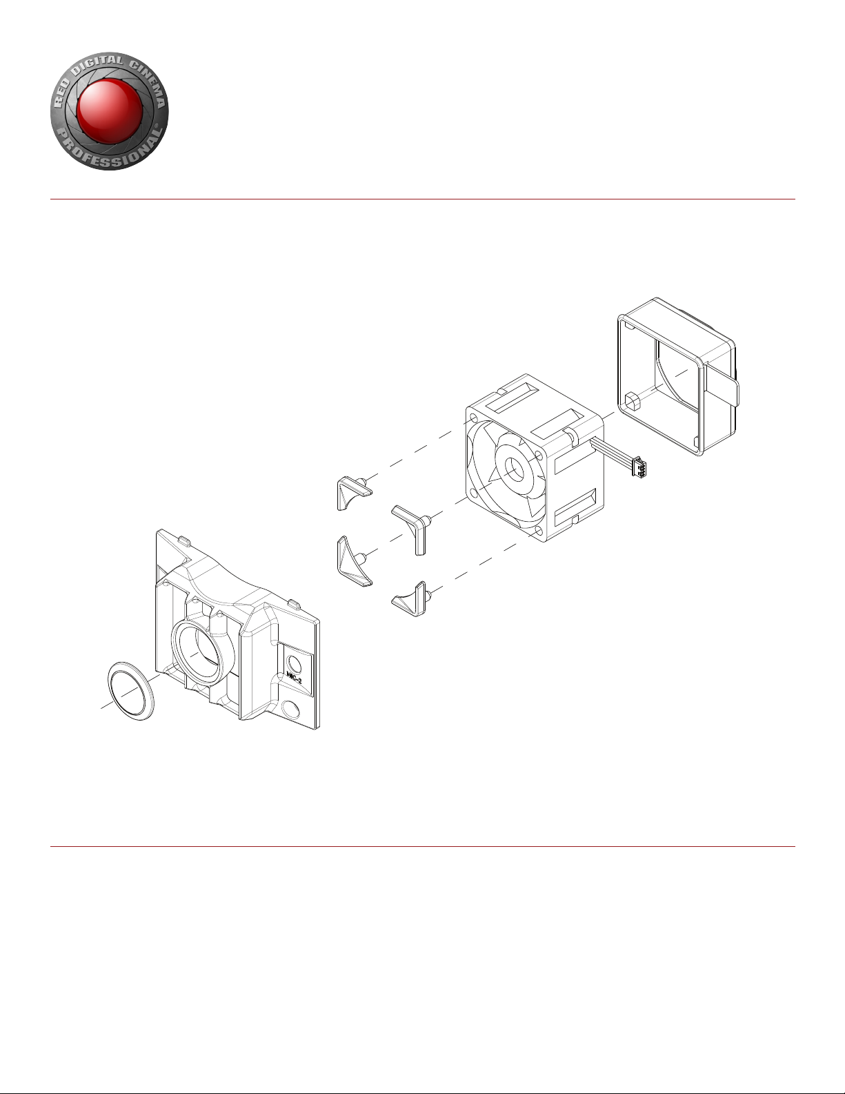
DSMC FAN 2.0 UPGRADE KIT COMPONENTS
DSMC FAN 2.0 UPGRADE KIT (TOP)
This kit includes the following components:
2.0 Top Fan Assembly
EPIC-X (black) or SCARLET-X (gray) top vent scoop
T6 Torx® driver (short)
T8 Torx® Allen key
Two (2) M2x0.4 x 4 mm cap screws
DSMC FAN 2.0 UPGRADE KIT (BOTTOM)
This kit includes the following components:
2.0 bottom fan assembly
Fan grill
T10 Torx® Allen key
Two (2) M3x0.5 x 6 mm cap screws
One (1) ESD-safe solder stick
DSMC FAN 2.0 UPGRADE KIT (TOP/BOTTOM)
This kit includes the following components:
2.0 Top Fan Assembly
EPIC-X (black) or SCARLET-X (gray) top vent scoop
T6 Torx® driver (short)
T8 Torx® Allen key
Two (2) M2x0.4 x 4 mm cap screws (top)
2.0 bottom fan assembly
Fan grill
T10 Torx® Allen key
Two (2) M3x0.5 x 6 mm cap screws (bottom)
One (1) ESD-safe solder stick
NOTE: Upon receiving your upgrade kit, please check to see if any components have been damaged or are missing. If there are damaged or missing parts, please file a support ticket with us at www.red.com/contact_us.
COPYRIGHT © 2014 RED.COM, INC
955-0012, REV-D | 7
Page 8
DSMC FAN 2.0 UPGRADE INSTRUCTIONS
UPGRADE
02
BOTTOM FAN
REQUIRED TOOLS
T10 Torx driver
ESD-safe solder stick (included)
REMOVE CURRENT BOTTOM FAN
1. Turn off the DSMC and remove all power sources, DSMC accessories, the lens, and the lens mount.
2. Cover the camera opening with a DSMC Front Body Cap to protect your sensor from dust and foreign par-
ticles during the fan upgrade procedure.
3. Place the DSMC BRAIN on a suitable flat work surface with the front of the DSMC facing upward.
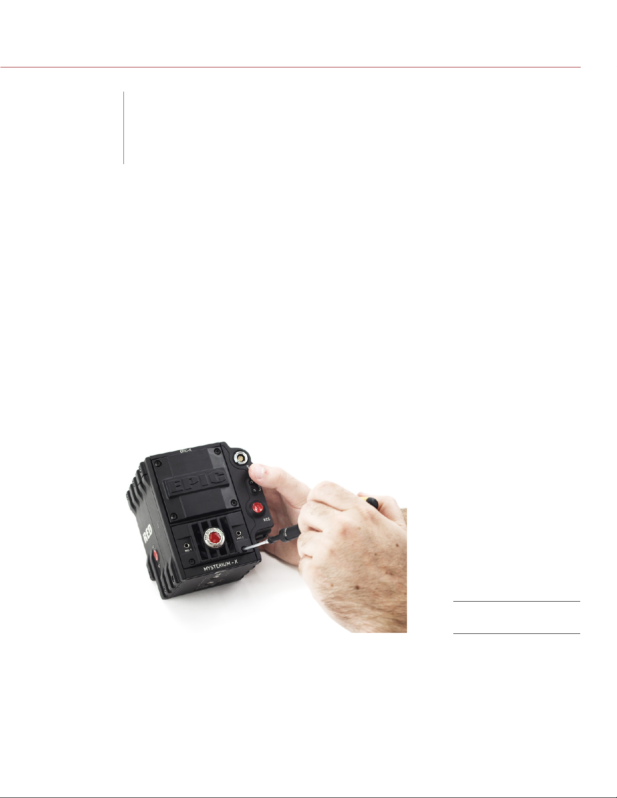
4. Use a T10 Torx driver to remove the two (2) M3x0.5 x 6 mm cap screws that attach the current fan grill to
the DSMC BRAIN.
COPYRIGHT © 2014 RED.COM, INC
Remove Cap Screws
955-0012, REV-D | 8
Page 9
DSMC FAN 2.0 UPGRADE INSTRUCTIONS
5. Remove the fan grill by rotating it upward, using the ESD-safe solder stick (included) for assistance if nec-
essary.
Remove Grill
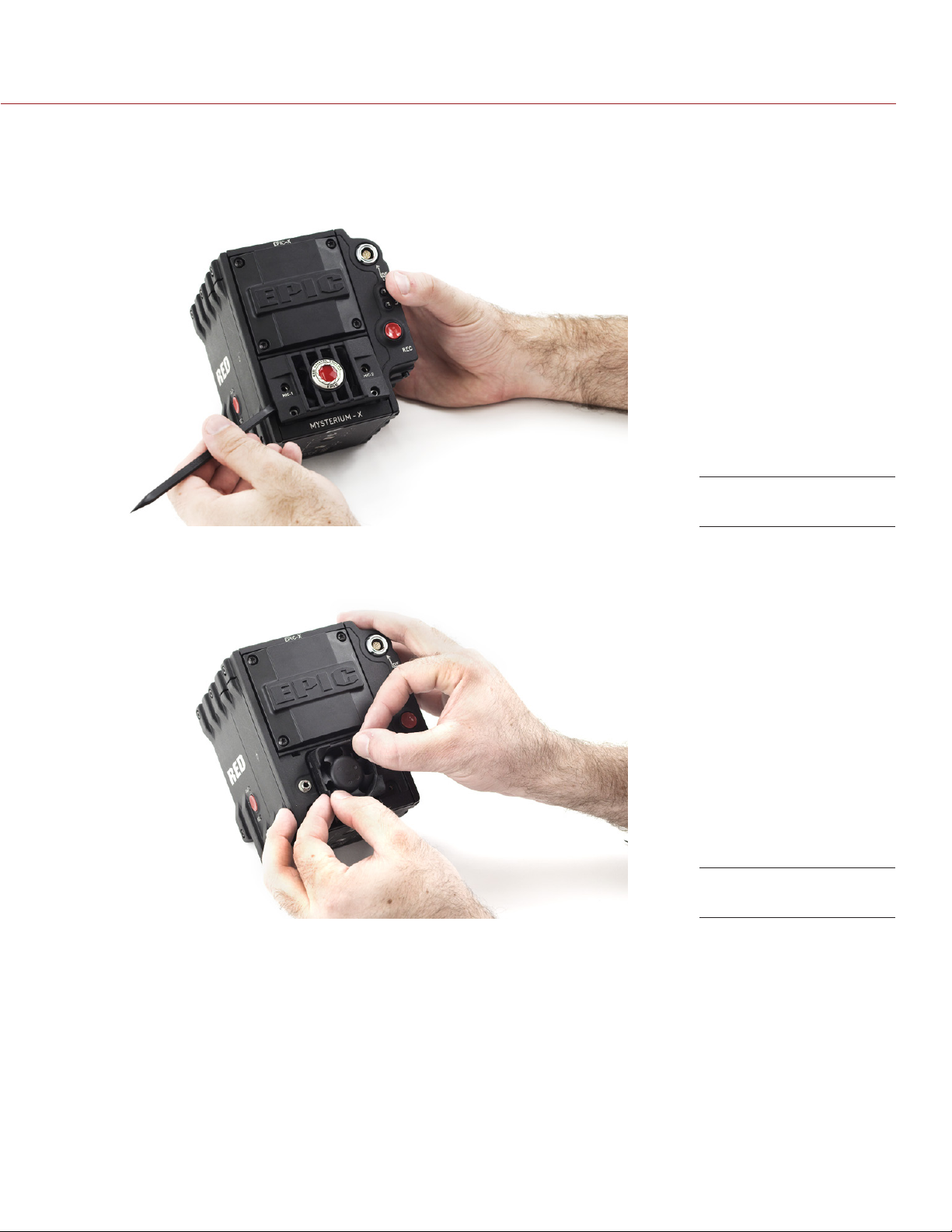
6. Pinch the upper right and lower left corners of the current fan assembly.
Pinch Fan Corners
NOTE: In the next step, DO NOT pull out the connector, or damage will occur.
7. While continuing to hold the upper right and lower left corners of the current fan assembly, wiggle and pull
the fan assembly back-and-forth until it releases from the DSMC BRAIN.
COPYRIGHT © 2014 RED.COM, INC
955-0012, REV-D | 9
Page 10

DSMC FAN 2.0 UPGRADE INSTRUCTIONS
8. If the connector on your original fan assembly has a white tab, depress the white tab with the ESD-safe
solder stick and gently pull the cables until the connector is free.
If the connector does not have a white tab, gently pull the cables until the connector is free. Use the ESD-
safe solder stick for assistance if necessary.
Disconnect Fan
COPYRIGHT © 2014 RED.COM, INC
955-0012, REV-D | 10
Page 11

DSMC FAN 2.0 UPGRADE INSTRUCTIONS
INSTALL 2.0 BOTTOM FAN
NOTE: If any of the fan bumpers fall off of the fan assembly during the installation process, reattach the bumpers
and ensure that they are properly aligned.
1. Identify the new fan assembly.
2. Align the female connectors with the pins in the connector slot and verify the following:
‒ Verify that the blue wire is at the top, and the red wire is at the bottom.
‒ Verify that the connector enters the slot directly, and NOT on its side, so that the female connectors
align with the pins in the connector slot.
3. Carefully push the white connector into the appropriate slot on the DSMC BRAIN, using the ESD-safe sol-
der stick for assistance if necessary.
You will hear a click when the connector is successfully attached to the BRAIN.
Connect Fan
COPYRIGHT © 2014 RED.COM, INC
955-0012, REV-D | 11
Page 12

DSMC FAN 2.0 UPGRADE INSTRUCTIONS
4. Insert the new fan assembly so that the fan bumpers are facing away from the camera, and that the label
on the fan is facing inward toward the camera. Keep the front of the fan assembly tilted forward, and make
sure that the connector cables are under the surface.
NOTE: DO NOT push the fan assembly into the seat all the way. Installing the fan grill will secure the fan assembly.
Insert Fan
5. Install the fan grill by pointing the top of the fan grill downward and sliding both tabs into the slots below
the DSMC Front Body Cap, so that the grill lies flat on top of the fan assembly.
Install Fan Grill
COPYRIGHT © 2014 RED.COM, INC
955-0012, REV-D | 12
Page 13

DSMC FAN 2.0 UPGRADE INSTRUCTIONS
6. Use a T10 Torx driver to install the two (2) M3x0.5 x 6 mm cap screws (included) that attach the fan grill to
the DSMC BRAIN. DO NOT FULLY TIGHTEN.
Install Cap Screws
7. Tighten the M3x0.5 x 6 mm screws evenly. DO NOT exceed 70 in-oz, or damage may occur.
WARNING: DO NOT OVERTIGHTEN.
8. Reattach the lens mount, lens, and any DSMC accessories that you removed from the BRAIN.
9. Upgrade your firmware or perform a hardware rediscover to ensure that your camera recognizes the new
fan. For more information, go to “Configure Firmware” on page 26.
NOTE: If you need to replace any screws, please contact your Bomb Squad representative.
COPYRIGHT © 2014 RED.COM, INC
955-0012, REV-D | 13
Page 14

DSMC FAN 2.0 UPGRADE INSTRUCTIONS
INSTALL
03
TOP FAN
TOP FAN COMPATIBILITY
The table below describes which top plates are compatible with the top fan. All compatible top plates provide
sufficient clearance for the top fan.
Once again making obsolescence obsolete, RED provides a replacement top vent scoop in each DSMC FAN 2.0
UPGRADE KIT (TOP and BOTTOM/TOP), so that you can install a compatible top plate along with your top fan.
TOP PLATE PART NUMBER COMPATIBLE NOTES
EPIC-X top vent
scoop
SCARLET-X top
vent scoop 2.0
DSMC TACTICAL
TOP PLATE 2.0
125-2057 Yes This top plate currently ships with EPIC-X cameras, and is
included in the DSMC FAN 2.0 UPGRADE KIT (TOP and BOTTOM/TOP) — EPIC as a replacement for incompatible top
plates.
125-2057-02 Yes This top plate is included in the DSMC FAN 2.0 UPGRADE KIT
(TOP and BOTTOM/TOP) — SCARLET as a replacement for
incompatible top plates.
790-0383 Yes This second generation DSMC TACTICAL TOP PLATE is spe-
cially designed to provide extra efficiencies and clearance for
the DSMC top fan.
EPIC-M top vent
scoop
SCARLET-X top
vent scoop
DSMC TACTICAL
TOP PLATE
NOTE: The part number of each top vent scoop is marked on the bottom of the top vent scoop.
NOTE: Any top vent scoop part number that is not listed in the table above is not compatible with the top fan.
For more details about the DSMC TACTICAL TOP PLATE modification and trade-in options, please contact
upgrades@red.com.
125-2095 No If you have an EPIC-M top vent scoop, install the replacement
EPIC-X top vent scoop included in the DSMC FAN 2.0 UPGRADE KIT (TOP and BOTTOM/TOP) — EPIC when installing
the top fan.
NOTE: Please contact epic-m@red.com if you have an eligible
EPIC-M that has not already been sent in for the free upgrade
program. The upgrade program includes mechanical improvements and additional mounting points. The upgrade should be
performed before you install the top fan.
125-2100 No If you have a SCARLET-X top vent scoop, install the replace-
ment SCARLET-X top vent scoop 2.0 included in the DSMC
FAN 2.0 UPGRADE KIT (TOP and BOTTOM/TOP) — SCARLET
when installing the top fan.
790-0255 No If you currently have an original DSMC TACTICAL TOP PLATE,
you can either send in your DSMC TACTICAL TOP PLATE and
receive credit toward the purchase of a new DSMC TACTICAL
TOP PLATE 2.0, or you can send in your DSMC TACTICAL
TOP PLATE for modification by RED free of charge.
COPYRIGHT © 2014 RED.COM, INC
955-0012, REV-D | 14
Page 15

DSMC FAN 2.0 UPGRADE INSTRUCTIONS
INSTALL TOP FAN WITH TOP VENT SCOOP
REQUIRED TOOLS
T8 Torx driver
T6 Torx driver (included)
REMOVE TOP VENT SCOOP
1. Turn off the DSMC and remove all power supplies, DSMC accessories, and the lens.
2. Place the DSMC BRAIN on a suitable flat work surface with the top of the DSMC facing upward.
3. Use a T8 Torx driver to remove the four (4) M2.5x0.45 x 6 mm cap screws that attach the top vent scoop
to the DSMC BRAIN.
COPYRIGHT © 2014 RED.COM, INC
Remove Cap Screws
955-0012, REV-D | 15
Page 16

DSMC FAN 2.0 UPGRADE INSTRUCTIONS
4. Remove the top vent scoop from the DSMC BRAIN.
Remove Top
5. Use a T6 Torx driver (included) to remove the two (2) M2x0.4 x 4 mm cap screws from the exhaust fan pogo
cover (black plastic slip).
Remove Cap Screws
COPYRIGHT © 2014 RED.COM, INC
955-0012, REV-D | 16
Page 17

DSMC FAN 2.0 UPGRADE INSTRUCTIONS
6. Remove the exhaust fan pogo cover.
NOTE: Store the exhaust fan pogo cover and the two (2) M2x0.4 x 4 mm cap screws in a safe place, in case
you want to remove or replace the top fans at a later time.
Remove Cover
INSTALL TOP FAN AND TOP VENT SCOOP
1. Place the top fan assembly on top of the vent so that the “RED PRO” lettering is facing up and the con-
nector is facing down.
Align Top Fan
COPYRIGHT © 2014 RED.COM, INC
955-0012, REV-D | 17
Page 18

DSMC FAN 2.0 UPGRADE INSTRUCTIONS
2. Attach the top fan to the DSMC BRAIN by installing two (2) M2x0.4 x 4 mm cap screws (included) with a
T6 Torx driver (included).
3. Tighten the M2x0.4 x 4 mm cap screws evenly. DO NOT exceed 30 in-oz, or damage may occur.
WARNING: DO NOT OVERTIGHTEN.
4. Place the top vent scoop on top of the fan.
Install Top Fan
Place Top on Fan
COPYRIGHT © 2014 RED.COM, INC
955-0012, REV-D | 18
Page 19

DSMC FAN 2.0 UPGRADE INSTRUCTIONS
5. Attach the top vent scoop to the DSMC BRAIN by installing four (4) M3x0.5 x 6 mm cap screws with a T8
Torx driver. DO NOT FULLY TIGHTEN.
WARNING: DO NOT OVERTIGHTEN.
Install Cap Screws
6. Tighten the M3x0.5 x 6 mm cap screws evenly. DO NOT exceed 30 in-oz, or damage may occur.
WARNING: DO NOT OVERTIGHTEN.
7. Reattach any DSMC accessories that you may have removed from the DSMC BRAIN.
8. Upgrade your firmware or perform a hardware rediscover to ensure that your camera recognizes the new
fan. For more information, go to “Configure Firmware” on page 26.
NOTE: The top fan may not run immediately after turning on the DSMC, as the top fan runs when the DSMC
requires additional cooling power.
NOTE: If you need to replace any screws, please contact your Bomb Squad representative.
COPYRIGHT © 2014 RED.COM, INC
955-0012, REV-D | 19
Page 20

DSMC FAN 2.0 UPGRADE INSTRUCTIONS
INSTALL TOP FAN WITH DSMC TACTICAL TOP PLATE
REQUIRED TOOLS
T6 Torx driver (included)
3/16 inch Allen wrench
3mm Allen wrench
REMOVE DSMC TACTICAL TOP PLATE
1. Turn off the DSMC and remove all power supplies, DSMC accessories, and the lens.
2. Place the DSMC BRAIN on a suitable flat work surface with the top of the DSMC facing upward.
3. Use a 3mm Allen wrench to loosen the four (4) M4 captive screws by at least two (2) full turns.
4. Use a 3/16 Allen wrench to loosen the two (2) 1/4-20 screws.
5. Continue to loosen all screws until the plate can be removed.
COPYRIGHT © 2014 RED.COM, INC
Loosen M4 Screws
955-0012, REV-D | 20
Page 21

DSMC FAN 2.0 UPGRADE INSTRUCTIONS
6. Remove the plate.
Remove Top Plate
7. Use a T6 Torx driver (included) to remove the two (2) M2x0.4 x 4 mm cap screws from the exhaust fan pogo
cover (black plastic slip).
Remove Cap Screws
COPYRIGHT © 2014 RED.COM, INC
955-0012, REV-D | 21
Page 22

DSMC FAN 2.0 UPGRADE INSTRUCTIONS
8. Remove the exhaust fan pogo cover.
NOTE: Store the exhaust fan pogo cover and the two (2) M2x0.4 x 4 mm cap screws in a safe place, in case
you want to remove or replace the top fans at a later time.
Remove Cover
COPYRIGHT © 2014 RED.COM, INC
955-0012, REV-D | 22
Page 23

DSMC FAN 2.0 UPGRADE INSTRUCTIONS
INSTALL TOP FAN AND DSMC TACTICAL TOP PLATE 2.0
NOTE: The top plate installation instructions below are also applicable to the original DSMC TACTICAL TOP
PLATE that was modified by RED to accommodate the top fan.
1. Ensure that the original TACTICAL TOP PLATE and exhaust fan pogo cover are already removed from the
DSMC. For more information on removing the TACTICAL TOP PLATE and exhaust fan pogo cover, go to
“Remove DSMC TACTICAL TOP PLATE” on page 20.
2. Place the DSMC BRAIN on a suitable flat work surface with the top of the DSMC facing upward.
3. Place the top fan assembly on top of the vent so that the “RED PRO” lettering is facing up and the con-
nector is facing down.
Insert Top Fan
4. Attach the top fan to the DSMC BRAIN by installing two (2) M2x0.4 x 4 mm cap screws (included) with a T6
Torx driver (included). DO NOT FULLY TIGHTEN.
Install Top Fan
5. Tighten the M2x0.4 x 4 mm cap screws evenly. DO NOT exceed 30 in-oz, or damage may occur.
WARNING: DO NOT OVERTIGHTEN.
COPYRIGHT © 2014 RED.COM, INC
955-0012, REV-D | 23
Page 24

DSMC FAN 2.0 UPGRADE INSTRUCTIONS
6. Place the DSMC TACTICAL TOP PLATE 2.0 on top of the fan.
Place Plate on Fan
7. Align the captive screws in the plate with the threaded holes on top of the DSMC BRAIN.
8. Use a 3/16 inch Allen wrench to tighten the two (2) 1/4-20 screws by about two (2) turns. DO NOT FULLY
TIGHTEN.
Install 1/4-20 Screws
COPYRIGHT © 2014 RED.COM, INC
955-0012, REV-D | 24
Page 25

DSMC FAN 2.0 UPGRADE INSTRUCTIONS
9. Use a 3mm Allen wrench to tighten the four (4) M4 screws by about two (2) turns. DO NOT FULLY TIGHTEN.
Install M4 Screws
10. Fully tighten the 1/4-20 screws. DO NOT OVERTIGHTEN.
11. Tighten M4 screws in a cross pattern. DO NOT OVERTIGHTEN.
12. Reattach any DSMC accessories that you removed from the BRAIN.
13. Upgrade your firmware or perform a hardware rediscover to ensure that your camera recognizes the new
fan. For more information, go to “Configure Firmware” on page 26.
NOTE: The top fan may not run immediately after turning on the DSMC, as the top fan runs only when the
DSMC requires additional cooling power.
NOTE: If you need to replace any screws, please contact your Bomb Squad representative.
COPYRIGHT © 2014 RED.COM, INC
955-0012, REV-D | 25
Page 26

DSMC FAN 2.0 UPGRADE INSTRUCTIONS
CONFIGURE
04
RED recommends that you upgrade your DSMC firmware to v4.0.12 or later in order to have full control over
both the top and bottom fans. DSMC firmware v4.0.12 and later offers full hardware support for both fans, and
provides more robust and precise fan settings, so that you have full control over the speed and noise level of
the DSMC fans. Earlier versions of DSMC firmware do not fully support DSMC 2.0 fans.
FIRMWARE
UPGRADE FIRMWARE
1. Download the v4.0.12 (or later) firmware file for your DSMC from www.red.com/downloads.
2. Perform the firmware upgrade on your DSMC BRAIN.
NOTE: For more information on upgrading your DSMC firmware, refer to the DSMC Operation Guide online
at https://www.red.com/downloads.
PERFORM HARDWARE REDISCOVER
If you upgraded your firmware before installing the new fans, or if you’re not upgrading your firmware, perform
a manual hardware rediscover after you install new fans so that the DSMC firmware recognizes the new fans.
NOTE: The instructions below are specific to firmware version v4.0.12.
1. Turn on your DSMC.
2. Go to Menu > Settings > Maintenance.
3. Select Rediscover.
4. Select Yes to perform the hardware rediscover.
Wait for the DSMC BRAIN to shut down.
Hardware Rediscover
5. Power on the DSMC BRAIN.
The DSMC firmware rediscovers all hardware and caches the data for future boot cycles.
COPYRIGHT © 2014 RED.COM, INC
955-0012, REV-D | 26
Page 27

DSMC FAN 2.0 UPGRADE INSTRUCTIONS
ADJUST FAN SETTINGS
After installing the 2.0 fans and performing other necessary operations, adjust your fan settings to account for
the new top fan (if applicable), the increased speed of the bottom fan, and the new fan mode settings that are
available in firmware v4.0.12 and later.
NOTE: The instructions below are specific to firmware version v4.0.12.
1. Turn on your DSMC BRAIN.
2. Navigate to Menu > Settings > Setup > System > Fan Control.
3. Adjust the fan settings to meet your personal preferences or the needs of your project.
NOTE: For more information on upgrading your DSMC firmware, refer to the DSMC Operation Guide online
at https://www.red.com/downloads.
Adjust Fan Settings
COPYRIGHT © 2014 RED.COM, INC
955-0012, REV-D | 27
Page 28

RED DIGITAL CINEMA
COPYRIGHT© 2014 RED.COM, INC.
All trademarks, trade names, logos, icons, images, written material, code and product names used in association with the accompanying product are the copyrights, trademarks or other intellectual property owned and
controlled exclusively by RED.COM, INC.
 Loading...