


RTL8309SB
SINGLE-CHIP 9-PORT 10/100MBPS SWITCH CONTROLLER
DATASHEET
Rev. 1.4
09 July 2004
Track ID: JATR-1076-21

RTL8309SB
Datasheet
COPYRIGHT
©2004 Realtek Semiconductor Corp. All rights reserved. No part of this document may be reproduced, transmitted,
transcribed, stored in a retrieval system, or translated into any language in any form or by any means without the written
permission of Realtek Semiconductor Corp.
DISCLAIMER
Realtek provides this document “as is”, without warranty of any kind, neither expressed nor implied, including, but not limited
to, the particular purpose. Realtek may make improvements and/or changes in this document or in the product described in this
document at any time. This document could include technical inaccuracies or typographical errors.
TRADEMARKS
Realtek is a trademark of Realtek Semiconductor Corporation. Other names mentioned in this document are
trademarks/registered trademarks of their respective owners.
USING THIS DOCUMENT
This document provides detailed user guidelines to achieve the best performance when implementing a 2-layer board PC
design with the RTL8309SB Single-Chip 9-port 10/100Mbps Switch Controller.
Though every effort has been made to assure that this document is current and accurate, more information may have become
available subsequent to the production of this guide. In that event, please contact your Realtek representative for additional
information that may help in the development process.
Single-Chip 9-Port 10/100Mbps Switch Controller ii Track ID: JATR-1076-21 Rev. 1.4

REVISION HISTORY
RTL8309SB
Datasheet
Revision Release Date
1.0 2003/04/12 First release.
1.1 2003/05/15 Revised pin descriptions.
1.2 2003/12/01 Revised pin description of Dis_VLAN.
1.3 2004/06/10 Removed PHY0~PHY7 REG2 and REG3 info.
1.4 2004/07/09 Removed QoS feature for IPv6.
Summary
Revised description for Bi-color LED.
New Bi-color LED Reference Schematic figure.
Add 3.3V items to electrical characteristics.
Add thermal operating range temperatures.
Revised pin description of Max_Pause_Count.
Revised default VLAN membership configuration for Disable VLAN
function in PHY register 16.11.
Update default value of Differential Service Code Point [B] in EEPROM
and PHY registers.
Update default value of VLAN ID [A] membership in EERPOM.
Update default value of ISP MAC Address in EEPROM.
Update default value of Port 8 VLAN Index in EEPROM.
Revised the definition for WAN port specification in EEPROM and PHY
registers.
Revised the definition for CPU port specification in EEPROM and PHY
registers.
Removed the Bypass CRC function in EEPROM.
Removed the Good Link Quality Threshold function in EEPROM and
PHY registers.
Add explanation of Indirect Access Data in PHY 7 Register 17~20.
Update pin number ordering on Pin Description Table.
Change the term “Auto MDIX” to “Crossover Detection and auto
correction”.
Single-Chip 9-Port 10/100Mbps Switch Controller iii Track ID: JATR-1076-21 Rev . 1.4

RTL8309SB
Datasheet
Table of Contents
1. GENERAL D ESCRIPTION................................................................................................................................................1
2. FEATURES...........................................................................................................................................................................3
3. BLOCK DIAGRAM.............................................................................................................................................................4
4. PIN ASSIGNMENTS...........................................................................................................................................................5
5. PIN DESCRIPTIONS..........................................................................................................................................................7
5.1. MEDIA CONNECTION PINS ..........................................................................................................................................7
5.2. MII PORT MAC INTERFACE PINS ...............................................................................................................................7
5.3. MISCELLANEOUS PINS ................................................................................................................................................9
5.4. PORT LED PINS ..........................................................................................................................................................9
5.5. SERIAL EEPROM AND SMI PINS .............................................................................................................................11
5.6. STRAPPING PINS........................................................................................................................................................12
5.7. POWER PINS..............................................................................................................................................................16
6. EEPROM REGISTER DESCRIPTION..........................................................................................................................17
6.1. GLOBAL CONTROL REGISTERS..................................................................................................................................17
6.1.1. Global Control Register0...................................................................................................................................17
6.1.2. Global Control Register1...................................................................................................................................17
6.1.3. Global Control Register2...................................................................................................................................18
6.1.4. Global Control Register3...................................................................................................................................18
6.1.5. Global Control Register4...................................................................................................................................19
6.1.6. Global Control Register5...................................................................................................................................19
6.1.7. Global Control Register6...................................................................................................................................19
6.1.8. Global Control Register7...................................................................................................................................19
6.2. PORT 0~7 CONTROL PINS..........................................................................................................................................20
6.2.1. Port 0 Control 0..................................................................................................................................................20
6.2.2. Port 0 Control 1..................................................................................................................................................20
6.2.3. Port 0 Control 2..................................................................................................................................................21
6.2.4. Port 0 Control 3..................................................................................................................................................21
6.2.5. Port 0 Control 4..................................................................................................................................................21
6.2.6. IP Addr ess...........................................................................................................................................................22
6.2.7. Port 1 Control 0..................................................................................................................................................23
6.2.8. Port 1 Control 1..................................................................................................................................................23
Single-Chip 9-Port 10/100Mbps Switch Controller iv Track ID: JATR-1076-21 Rev. 1.4

RTL8309SB
Datasheet
6.2.9. Port 1 Control 2..................................................................................................................................................24
6.2.10. Port 1 Control 3..................................................................................................................................................24
6.2.11. Port 1 Control 4..................................................................................................................................................24
6.2.12. IP Mask ..............................................................................................................................................................25
6.2.13. Port 2 Control 0..................................................................................................................................................25
6.2.14. Port 2 Control 1..................................................................................................................................................26
6.2.15. Port 2 Control 2..................................................................................................................................................26
6.2.16. Port 2 Control 3..................................................................................................................................................26
6.2.17. Port 2 Control 4..................................................................................................................................................27
6.2.18. Switch MAC Address ..........................................................................................................................................27
6.2.19. Port 3 Control 0..................................................................................................................................................28
6.2.20. Port 3 Control 1..................................................................................................................................................28
6.2.21. Port 3 Control 2..................................................................................................................................................29
6.2.22. Port 3 Control 3..................................................................................................................................................29
6.2.23. Port 3 Control 4..................................................................................................................................................29
6.2.24. ISP MAC Address...............................................................................................................................................30
6.2.25. Port 4 Control 0..................................................................................................................................................30
6.2.26. Port 4 Control 1..................................................................................................................................................30
6.2.27. Port 4 Control 2..................................................................................................................................................31
6.2.28. Port 4 Control 3..................................................................................................................................................31
6.2.29. Port 4 Control 4..................................................................................................................................................31
6.3. MII PORT CONTROL PINS..........................................................................................................................................32
6.3.1. MII Port Control 0..............................................................................................................................................32
6.3.2. MII Port Control 1..............................................................................................................................................32
6.3.3. MII Port Control 2..............................................................................................................................................33
6.3.4. CPU Port and WAN Port....................................................................................................................................33
6.4. PORT 5~7 CONTROL PINS..........................................................................................................................................34
6.4.1. Port 5 Control 0..................................................................................................................................................34
6.4.2. Port 5 Control 1..................................................................................................................................................34
6.4.3. Port 5 Control 2..................................................................................................................................................35
6.4.4. Port 5 Control 3..................................................................................................................................................35
6.4.5. Port 5 Control 4..................................................................................................................................................35
6.4.6. Port 6 Control 0..................................................................................................................................................36
6.4.7. Port 6 Control 1..................................................................................................................................................36
6.4.8. Port 6 Control 2..................................................................................................................................................36
Single-Chip 9-Port 10/100Mbps Switch Controller v Track ID: JATR-1076-21 Rev. 1.4

RTL8309SB
Datasheet
6.4.9. Port 6 Control 3..................................................................................................................................................37
6.4.10. Port 6 Control 4..................................................................................................................................................37
6.4.11. Port 7 Control 0..................................................................................................................................................38
6.4.12. Port 7 Control 1..................................................................................................................................................38
6.4.13. Port 7 Control 2..................................................................................................................................................38
6.4.14. Port 7 Control 3..................................................................................................................................................39
6.4.15. Port 7 Control 4..................................................................................................................................................39
7. PHY REGISTERS DESCRIPTION.................................................................................................................................40
7.1. PHY 0 REGISTERS ....................................................................................................................................................40
7.1.1. PHY 0 Register 0: Control.................................................................................................................................. 40
7.1.2. PHY 0 Register 1: Status ....................................................................................................................................41
7.1.3. PHY 0 Register 4: Auto-Negotiation Advertisement...........................................................................................42
7.1.4. PHY 0 Register 5: Auto-Negotiation Link Partner Ability..................................................................................42
7.1.5. PHY 0 Register 6: Auto-Negotiation Expansion.................................................................................................43
7.1.6. PHY 0 Register 16: Global Control 0.................................................................................................................43
7.1.7. PHY 0 Register 17: Global Control 1.................................................................................................................45
7.1.8. PHY 0 Register 18: Global Control 2.................................................................................................................46
7.1.9. PHY 0 Register 19: Global Control 3.................................................................................................................46
7.1.10. PHY 0 Register 22: Port 0 Control 0..................................................................................................................46
7.1.11. PHY 0 Register 23: Port 0 Control 1..................................................................................................................48
7.1.12. PHY 0 Register 24: Port 0 Control 2 & VLAN Entry [A]...................................................................................48
7.1.13. PHY 0 Register 25: VLAN Entry [A]..................................................................................................................48
7.2. PHY 1 REGISTERS ....................................................................................................................................................49
7.2.1. PHY 1 Register 0: Control.................................................................................................................................. 49
7.2.2. PHY 1 Register 1: Status ....................................................................................................................................49
7.2.3. PHY 1 Register 4: Auto-Negotiation Advertisement...........................................................................................49
7.2.4. PHY 1 Register 5: Auto-Negotiation Link Partner Ability..................................................................................49
7.2.5. PHY 1 Register 6: Auto-Negotiation Expansion.................................................................................................49
7.2.6. PHY 1 Register 16~17: IP Priority Address [A].................................................................................................49
7.2.7. PHY 1 Register 18~19: IP Priority Address [B].................................................................................................49
7.2.8. PHY 1 Register 22: Port 1 Control 0..................................................................................................................50
7.2.9. PHY 1 Register 23: Port 1 Control 1..................................................................................................................50
7.2.10. PHY 1 Register 24: Port 1 Control 2 & VLAN Entry [B]...................................................................................50
7.2.11. PHY 1 Register 25: VLAN Entry [B]..................................................................................................................50
Single-Chip 9-Port 10/100Mbps Switch Controller vi Track ID: JATR-1076-21 Rev. 1.4

RTL8309SB
Datasheet
7.3. PHY 2 REGISTERS ....................................................................................................................................................50
7.3.1. PHY 2 Register 0: Control.................................................................................................................................. 50
7.3.2. PHY 2 Register 1: Status ....................................................................................................................................50
7.3.3. PHY 2 Register 4: Auto-Negotiation Advertisement...........................................................................................50
7.3.4. PHY 2 Register 5: Auto-Negotiation Link Partner Ability..................................................................................51
7.3.5. PHY 2 Register 6: Auto-Negotiation Expansion.................................................................................................51
7.3.6. PHY 2 Register 16~17: IP Priority Mask [A] ....................................................................................................51
7.3.7. PHY 2 Register 18~19: IP Priority Mask [B] ....................................................................................................51
7.3.8. PHY 2 Register 22: Port 2 Control 0..................................................................................................................51
7.3.9. PHY 2 Register 23: Port 2 Control 1..................................................................................................................51
7.3.10. PHY 2 Register 24: Port 2 Control 2 & VLAN Entry [C]...................................................................................52
7.3.11. PHY 2 Register 25: VLAN Entry [C]..................................................................................................................52
7.4. PHY 3 REGISTERS ....................................................................................................................................................52
7.4.1. PHY 3 Register 0: Control.................................................................................................................................. 52
7.4.2. PHY 3 Register 1: Status ....................................................................................................................................52
7.4.3. PHY 3 Register 4: Auto-Negotiation Advertisement...........................................................................................52
7.4.4. PHY 3 Register 5: Auto-Negotiation Link Partner Ability..................................................................................52
7.4.5. PHY 3 Register 6: Auto-Negotiation Expansion.................................................................................................52
7.4.6. PHY 3 Register 16~18: Switch MAC Address ....................................................................................................52
7.4.7. PHY 3 Register 22: Port 3 Control 0..................................................................................................................53
7.4.8. PHY 3 Register 23: Port 3 Control 1..................................................................................................................53
7.4.9. PHY 3 Register 24: Port 3 Control 2 & VLAN Entry [D]..................................................................................53
7.4.10. PHY 3 Register 25: VLAN Entry [D]..................................................................................................................53
7.5. PHY 4 REGISTERS ....................................................................................................................................................54
7.5.1. PHY 4 Register 0: Control.................................................................................................................................. 54
7.5.2. PHY 4 Register 1: Status ....................................................................................................................................54
7.5.3. PHY 4 Register 4: Auto-Negotiation Advertisement...........................................................................................54
7.5.4. PHY 4 Register 5: Auto-Negotiation Link Partner Ability..................................................................................54
7.5.5. PHY 4 Register 6: Auto-Negotiation Expansion.................................................................................................54
7.5.6. PHY 4 Register 16~18: ISP MAC Address......................................................................................................... 54
7.5.7. PHY 4 Register 22: Port 4 Control 0..................................................................................................................54
7.5.8. PHY 4 Register 23: Port 4 Control 1..................................................................................................................54
7.5.9. PHY 4 Register 24: Port 4 Control 2 & VLAN Entry [E]...................................................................................55
7.5.10. PHY 4 Register 25: VLAN Entry [E]..................................................................................................................55
Single-Chip 9-Port 10/100Mbps Switch Controller vii Track ID: JATR-1076-21 Rev. 1.4

RTL8309SB
Datasheet
7.6. PHY 5 REGISTERS ....................................................................................................................................................55
7.6.1. PHY 5 Register 0: Control.................................................................................................................................. 55
7.6.2. PHY 5 Register 1: Status ....................................................................................................................................55
7.6.3. PHY 5 Register 4: Auto-Negotiation Advertisement...........................................................................................55
7.6.4. PHY 5 Register 5: Auto-Negotiation Link Partner Ability..................................................................................55
7.6.5. PHY 5 Register 6: Auto-Negotiation Expansion.................................................................................................55
7.6.6. PHY 5 Register 16: MII Port Control 0..............................................................................................................56
7.6.7. PHY 5 Register 17: MII Port Control 1 & VLAN Entry [I]................................................................................57
7.6.8. PHY 5 Register 18: VLAN Entry [I]...................................................................................................................57
7.6.9. PHY 5 Register 19: CPU Port & WAN Port.......................................................................................................57
7.6.10. PHY 5 Register 22: Port 5 Control 0..................................................................................................................58
7.6.11. PHY 5 Register 23: Port 5 Control 1..................................................................................................................58
7.6.12. PHY 5 Register 24: Port 5 Control 2 & VLAN Entry [F]...................................................................................58
7.6.13. PHY 5 Register 25: VLAN Entry [F]..................................................................................................................58
7.7. PHY 6 REGISTERS ....................................................................................................................................................59
7.7.1. PHY 6 Register 0: Control.................................................................................................................................. 59
7.7.2. PHY 6 Register 1: Status ....................................................................................................................................59
7.7.3. PHY 6 Register 4: Auto-Negotiation Advertisement...........................................................................................59
7.7.4. PHY 6 Register 5: Auto-Negotiation Link Partner Ability..................................................................................59
7.7.5. PHY 6 Register 6: Auto-Negotiation Expansion.................................................................................................59
7.7.6. PHY 6 Register 22: Port 6 Control 0..................................................................................................................59
7.7.7. PHY 6 Register 23: Port 6 Control 1..................................................................................................................59
7.7.8. PHY 6 Register 24: Port 6 Control 2 & VLAN Entry [G]..................................................................................60
7.7.9. PHY 6 Register 25: VLAN Entry [G]..................................................................................................................60
7.8. PHY 7 REGISTERS ....................................................................................................................................................61
7.8.1. PHY 7 Register 0: Control.................................................................................................................................. 61
7.8.2. PHY 7 Register 1: Status ....................................................................................................................................61
7.8.3. PHY 7 Register 4: Auto-Negotiation Advertisement...........................................................................................61
7.8.4. PHY 7 Register 5: Auto-Negotiation Link Partner Ability..................................................................................61
7.8.5. PHY 7 Register 6: Auto-Negotiation Expansion.................................................................................................61
7.8.6. PHY 7 Register 16: indirect Access Control.......................................................................................................61
7.8.7. PHY 7 Register 17~20: Indirect Access Data.....................................................................................................62
7.8.8. PHY 7 Register 22: Port 7 Control 0..................................................................................................................62
7.8.9. PHY 7 Register 23: Port 7 Control 1..................................................................................................................62
Single-Chip 9-Port 10/100Mbps Switch Controller viii Track ID: JATR-1076-21 Rev. 1.4

RTL8309SB
Datasheet
7.8.10. PHY 7 Register 24: Port 7 Control 2 & VLAN Entry [H] ..................................................................................62
7.8.11. PHY 7 Register 25: VLAN Entry [H]..................................................................................................................63
7.9. PHY 8 REGISTERS ....................................................................................................................................................63
7.9.1. PHY 8 Register 0: Control.................................................................................................................................. 63
7.9.2. PHY 8 Register 1: Status ....................................................................................................................................64
7.9.3. PHY 8 Register 4: Auto-Negotiation Advertisement...........................................................................................64
7.9.4. MII Port NWay Mode .........................................................................................................................................65
7.9.5. MII Port Force Mode.........................................................................................................................................65
8. FUNCTIONAL DESCRIPTION.......................................................................................................................................66
8.1. PHYSICAL LAYE R TRANSCEIVER FUNCTIONAL OVERVIEW .......................................................................................66
8.1.1. Auto Negotiation for UTP ..................................................................................................................................66
8.1.2. 100Base-Tx T ransmit Function ..........................................................................................................................66
8.1.3. 100Base-Tx Receive Function............................................................................................................................66
8.1.4. 10Base-T T r ansmit Function..............................................................................................................................67
8.1.5. 10Base-T Receive Function................................................................................................................................67
8.1.6. Link Monitor.......................................................................................................................................................67
8.1.7. Power Saving Mode............................................................................................................................................67
8.1.8. Power-Down Mode.............................................................................................................................................67
8.1.9. Auto Crossover Detection...................................................................................................................................68
8.2. SWITCH CORE FUNCTIONAL OVERVIEW....................................................................................................................68
8.2.1. Address Search, Learning, and Aging................................................................................................................68
8.2.2. Flow Control...................................................................................................................................................... 69
8.2.3. Half Duplex Operation.......................................................................................................................................69
8.2.4. Backpressure ......................................................................................................................................................70
8.2.5. UTP Port Status Configuration..........................................................................................................................70
8.2.6. MII Port (The 9th Port)......................................................................................................................................70
8.3. ADVANCED FUNCTIONALITY OVERVIEW...................................................................................................................74
8.3.1. Port-Based VLAN...............................................................................................................................................74
8.3.2. 802.1Q Tagged-VID based VLAN.......................................................................................................................76
8.3.3. QoS Operation....................................................................................................................................................77
8.3.4. Insert/Remove VLAN Priority Tag......................................................................................................................78
8.3.5. Port VID (PVID) ................................................................................................................................................79
8.3.6. Port Trunking.....................................................................................................................................................79
8.3.7. ISP MAC Address Translation............................................................................................................................79
8.3.8. Lookup Table Access...........................................................................................................................................81
Single-Chip 9-Port 10/100Mbps Switch Controller ix Track ID: JATR-1076-21 Rev. 1.4

RTL8309SB
Datasheet
8.3.9. Serial Management Interface (SMI)...................................................................................................................81
8.3.10. Broadcast S t orm Control....................................................................................................................................82
8.3.11. Broadcast In/Out Drop.......................................................................................................................................82
8.3.12. EEPROM Configuration Interface.....................................................................................................................83
8.3.13. 24LC02 Device Operation..................................................................................................................................83
8.3.14. Head-of-Line Blocking.......................................................................................................................................84
8.3.15. MII Port Diagnostic Loopback...........................................................................................................................85
8.3.16. Loop Detection...................................................................................................................................................86
8.3.17. LEDs (Light Emitting Diodes)............................................................................................................................87
9. CHARACTERISTICS.......................................................................................................................................................90
9.1. ABSOLUTE MAXIMUM RATI N G S ................................................................................................................................90
9.2. OPERATING RANGE ...................................................................................................................................................90
9.3. DC CHARACTERISTICS .............................................................................................................................................90
9.4. AC CHARACTERISTICS .............................................................................................................................................91
9.5. DIGITAL TIMING CHARACTERISTICS .........................................................................................................................92
9.6. THERMAL CHARACTERISTICS ...................................................................................................................................94
10. SYSTEM APPLICA TIONS...........................................................................................................................................95
11. DESIGN AND LA YOUT GUIDE..................................................................................................................................96
12. MECHANICAL DIMENSIONS................................................................................................................................... 99
12.1. NOTES FOR 128-PIN PQFP DIMENSIONS ................................................................................................................100
Single-Chip 9-Port 10/100Mbps Switch Controller x Track ID: JATR-1076-21 Rev. 1.4

RTL8309SB
Datasheet
List of Tables
Table 1. Pin Assignments.............................................................................................................................6
Table 2. Media Connection Pins..................................................................................................................7
Table 3. MII Port MAC Interface Pins ........................................................................................................7
Table 4. Miscellaneous Pins.........................................................................................................................9
Table 5. Port LED Pins ................................................................................................................................9
Table 6. Serial EEPROM and SMI Pins ....................................................................................................11
Table 7. Strapping Pins ..............................................................................................................................12
Table 8. Power Pins ...................................................................................................................................16
Table 9. Global Control Register0 .............................................................................................................17
Table 10. Global Control Register1 .............................................................................................................17
Table 11. Global Control Register2 .............................................................................................................18
Table 12. Global Control Register3 .............................................................................................................18
Table 13. Global Control Register4 .............................................................................................................19
Table 14. Global Control Register5 .............................................................................................................19
Table 15. Global Control Register6 .............................................................................................................19
Table 16. Global Control Register7 .............................................................................................................19
Table 17. Port 0 Control 0............................................................................................................................20
Table 18. Port 0 Control 1............................................................................................................................20
Table 19. Port 0 Control 2............................................................................................................................21
Table 20. Port 0 Control 3............................................................................................................................21
Table 21. Port 0 Control 4............................................................................................................................21
Table 22. IP Address ....................................................................................................................................22
Table 23. Port 1 Control 0............................................................................................................................23
Table 24. Port 1 Control 1............................................................................................................................23
Table 25. Port 1 Control 2............................................................................................................................24
Table 26. Port 1 Control 3............................................................................................................................24
Table 27. Port 1 Control 4............................................................................................................................24
Table 28. IP Mask ........................................................................................................................................25
Table 29. Port 2 Control 0............................................................................................................................25
Table 30. Port 2 Control 1............................................................................................................................26
Table 31. Port 2 Control 2............................................................................................................................26
Table 32. Port 2 Control 3............................................................................................................................26
Table 33. Port 2 Control 4............................................................................................................................27
Single-Chip 9-Port 10/100Mbps Switch Controller xi Track ID: JATR-1076-21 Rev. 1.4

RTL8309SB
Datasheet
Table 34. Switch MAC Address ..................................................................................................................27
Table 35. Port 3 Control 0............................................................................................................................28
Table 36. Port 3 Control 1............................................................................................................................28
Table 37. Port 3 Control 2............................................................................................................................29
Table 38. Port 3 Control 3............................................................................................................................29
Table 39. Port 3 Control 4............................................................................................................................29
Table 40. ISP MAC Address........................................................................................................................30
Table 41. Port 4 Control 0............................................................................................................................30
Table 42. Port 4 Control 1............................................................................................................................30
Table 43. Port 4 Control 2............................................................................................................................31
Table 44. Port 4 Control 3............................................................................................................................31
Table 45. Port 4 Control 4............................................................................................................................31
Table 46. MII Port Control 0 .......................................................................................................................32
Table 47. MII Port Control 1 .......................................................................................................................32
Table 48. MII Port Control 2 .......................................................................................................................33
Table 49. CPU Port and WAN Port..............................................................................................................33
Table 50. Port 5 Control 0............................................................................................................................34
Table 51. Port 5 Control 1............................................................................................................................34
Table 52. Port 5 Control 2............................................................................................................................35
Table 53. Port 5 Control 3............................................................................................................................35
Table 54. Port 5 Control 4............................................................................................................................35
Table 55. Port 6 Control 0............................................................................................................................36
Table 56. Port 6 Control 1............................................................................................................................36
Table 57. Port 6 Control 2............................................................................................................................36
Table 58. Port 6 Control 3............................................................................................................................37
Table 59. Port 6 Control 4............................................................................................................................37
Table 60. Port 7 Control 0............................................................................................................................38
Table 61. Port 7 Control 1............................................................................................................................38
Table 62. Port 7 Control 2............................................................................................................................38
Table 63. Port 7 Control 3............................................................................................................................39
Table 64. Port 7 Control 4............................................................................................................................39
Table 65. PHY 0 Register 0: Control...........................................................................................................40
Table 66. PHY 0 Register 1: Status .............................................................................................................41
Table 67. PHY 0 Register 4: Auto-Negotiation Advertisement...................................................................42
Table 68. PHY 0 Register 5: Auto-Negotiation Link Partner Ability..........................................................42
Single-Chip 9-Port 10/100Mbps Switch Controller xii Track ID: JATR-1076-21 Rev. 1.4

RTL8309SB
Datasheet
Table 69. PHY 0 Register 6: Auto-Negotiation Expansion .........................................................................43
Table 70. PHY 0 Register 16: Global Control 0..........................................................................................43
Table 71. PHY 0 Register 17: Global Control 1..........................................................................................45
Table 72. PHY 0 Register 18: Global Control 2..........................................................................................46
Table 73. PHY 0 Register 19: Global Control 3..........................................................................................46
Table 74. PHY 0 Register 22: Port 0 Control 0 ...........................................................................................46
Table 75. PHY 0 Register 23: Port 0 Control 1 ...........................................................................................48
Table 76. PHY 0 Register 24: Port 0 Control 2 & VLAN Entry [A]...........................................................48
Table 77. PHY 0 Register 25: VLAN Entry [A]..........................................................................................48
Table 78. PHY 1 Register 16~17: IP Priority Address [A]..........................................................................49
Table 79. PHY 1 Register 18~19: IP Priority Address [B] ..........................................................................49
Table 80. PHY 1 Register 24: Port 1 Control 2 & VLAN Entry [B]...........................................................50
Table 81. PHY 1 Register 25: VLAN Entry [B]..........................................................................................50
Table 82. PHY 2 Register 16~17: IP Priority Mask [A]..............................................................................51
Table 83. PHY 2 Register 18~19: IP Priority Mask [B] ..............................................................................51
Table 84. PHY 2 Register 24: Port 2 Control 2 & VLAN Entry [C]...........................................................52
Table 85. PHY 2 Register 25: VLAN Entry [C]..........................................................................................52
Table 86. PHY 3 Register 16~18: Switch MAC Address ............................................................................53
Table 87. PHY 3 Register 24: Port 3 Control 2 & VLAN Entry [D]...........................................................53
Table 88. PHY 3 Register 25: VLAN Entry [D]..........................................................................................53
Table 89. PHY 4 Register 16~18: ISP MAC Address .................................................................................54
Table 90. PHY 4 Register 24: Port 4 Control 2 & VLAN Entry [E] ...........................................................55
Table 91. PHY 4 Register 25: VLAN Entry [E] ..........................................................................................55
Table 92. PHY 5 Register 16: MII Port Control 0.......................................................................................56
Table 93. PHY 5 Register 17: MII Port Control 1 & VLAN Entry [I] ........................................................57
Table 94. PHY 5 Register 18: VLAN Entry [I] ...........................................................................................57
Table 95. PHY 5 Register 19: CPU Port & WAN Port ................................................................................57
Table 96. PHY 5 Register 24: Port 5 Control 2 & VLAN Entry [F] ...........................................................58
Table 97. PHY 5 Register 25: VLAN Entry [F] ..........................................................................................58
Table 98. PHY 6 Register 24: Port 6 Control 2 & VLAN Entry [G]...........................................................60
Table 99. PHY 6 Register 25: VLAN Entry [G]..........................................................................................60
Table 100. PHY 7 Register 16: Indirect Access Control .............................................................................61
Table 101. PHY 7 Register 17~20: Indirect Access Data............................................................................62
Table 102. PHY 7 Register 24: Port 7 Control 2 & VLAN Entry [H].........................................................62
Table 103. PHY 7 Register 25: VLAN Entry [H]........................................................................................63
Single-Chip 9-Port 10/100Mbps Switch Controller xiii Track ID: JATR-1076-21 Rev. 1.4

RTL8309SB
Datasheet
Table 104. PHY 8 Register 0: Control.........................................................................................................63
Table 105. PHY 8 Register 1: Status............................................................................................................64
Table 106. PHY 8 Register 4: Auto-Negotiation Advertisement.................................................................64
Table 107. MII Port NWay Mode ................................................................................................................65
Table 108. MII Port Force Mode .................................................................................................................65
Table 109. 802.1Q VLAN Tag Frame Format .............................................................................................78
Table 110. IPv4 Frame Format ....................................................................................................................78
Table 111. SMI Read/Write Cycles..............................................................................................................81
Table 112. Loop Frame Format ...................................................................................................................86
Table 113. Speed and Bi-Color Link/Act Truth Table.................................................................................88
Table 114. Absolute Maximum Ratings.......................................................................................................90
Table 115. Operating Range ........................................................................................................................90
Table 116. DC Characteristics .....................................................................................................................90
Table 117. AC Characteristics......................................................................................................................91
Table 118. Digital Timing Characteristics ...................................................................................................93
Table 119. Thermal Operating Range..........................................................................................................94
Table 120. Thermal Resistance....................................................................................................................95
Single-Chip 9-Port 10/100Mbps Switch Controller xiv Track ID: JATR-1076-21 Rev. 1.4

RTL8309SB
Datasheet
List of Figures
Figure 1. Block Diagram .............................................................................................................................4
Figure 2. Pin Assignments ...........................................................................................................................5
Figure 3. MII Port Application ..................................................................................................................71
Figure 4. MII Port Operating Mode Overview..........................................................................................72
Figure 5. VLAN Grouping Example .........................................................................................................75
Figure 6. Tagged and Untagged Packet Forwarding When 802.1Q Tag Aware VLAN is Disabled .........76
Figure 7. ISP MAC Outbound Process......................................................................................................80
Figure 8. ISP MAC Inbound Process.........................................................................................................80
Figure 9. Input Drop vs. Output Drop .......................................................................................................82
Figure 10. Start and Stop Definition............................................................................................................83
Figure 11. Output Acknowledge ..................................................................................................................84
Figure 12. Random Read .............................................................................................................................84
Figure 13. Sequential Read..........................................................................................................................84
Figure 14. MII Port Loopback .....................................................................................................................85
Figure 15. Loop Example ............................................................................................................................86
Figure 16. Floating and Pull-down of LED Pins .........................................................................................87
Figure 17. Two-Pin Bi-Color LED for SPD Floating or Pull-high..............................................................88
Figure 18. Two-Pin Bi-Color LED for SPD Pull-down...............................................................................88
Figure 19. Bi-Color LED Reference Schematic..........................................................................................89
Figure 20. Reception Data Timing of MII/SNI/SMI Interface ....................................................................92
Figure 21. Transmission Data Timing of MII/SNI/SMI Interface...............................................................92
Figure 22. Cross-section of 128-Pin PQFP..................................................................................................94
Figure 23. Application for Transformer with Connected Central Tap.........................................................97
Figure 24. Bob Smith Termination ..............................................................................................................98
Single-Chip 9-Port 10/100Mbps Switch Controller xv Track ID: JATR-1076-21 Rev. 1.4

RTL8309SB
Datasheet
1. General Description
The RTL8309SB is a 128-pin, ultra low power, high-performance 8-port Fast Ethernet single-chip switch
with one extra MII port for specific applications. It integrates all the functions of a high speed switch
system—including SRAM for packet buffering, non-blocking switch fabric, address management, one
general use MII interface, eight 10/100Base-TX transceivers, and nine Media Access Controllers—into a
single 0.18µm CMOS device. It provides compatibility with all industry standard Ethernet and Fast
Ethernet devices. Only a 25MHz crystal is required; the EEPROM is optional to save BOM costs.
The embedded packet storage SRAM in the RTL8309SB features superior memory management
technology to efficiently utilize the memory space. An integrated 1024-entry look-up table stores MAC
address and associated information in a 10-bit direct mapping scheme. The table provides read/write
access from the SMI interface, and each of the entries can be configured as a static entry. A static entry
indicates that this entry is controlled by the external management processor and automatic aging and
learning of the entry will not take place. To prevent MAC address mapping collisions, the embedded 16-
entry Content-Addressable Memory (CAM) offers another memory space for recording the MAC address
when the mapped entry in the lookup table is occupied. For each incoming packet, the RTL8309SB
searches the entries in the lookup table and the 16-entry CAM simultaneously. Then it obtains the correct
destination port information to determine which output port the packet should be forwarded to. The aging
time of the RTL8309SB is around 300 seconds (this may be sped up to 800µs via EEPROM
configuration).
The ninth port of the RTL8309SB implements a MAC module without a PHY transceiver to provide an
MII interface for connection with an external PHY or MAC in specific applications. This MII interface
may be set to MII PHY mode, SNI PHY mode, or MII MAC mode to work with an external MAC
module in a routing engine application, PHY module in a HomePNA application, or other physical layer
transceivers. In order to operate correctly, both sides of the connection must be configured to the same
speed, duplex, and flow control settings. Four pins are used for the ninth port to force the link status. This
interface should be 2.5V or 3.3V compatible depending on the voltage supplied to the power pin VDDIO
of this interface.
The RTL8309SB is capable of preventing broadcast storms by setting strapping pins upon system reset.
When this function is enabled, it will drop broadcast packets after receiving 64 continuous broadcast
packets. This counter will be reset to 0 every 800ms or when the RTL8309SB receives a non-broadcast
packet.
The RTL8309SB displays the port status via four LED indicators (with optional blinking time setting).
These LEDs blink for diagnostic purposes at system reset time. The RTL8309SB provides various type of
Single-Chip 9-Port 10/100Mbps Switch Controller 1 Track ID: JATR-1076-21 Rev. 1.4

RTL8309SB
Datasheet
LED combinations to fit different applications. Eight combinations of link, activity, speed, duplex, and
collision, are available. Bi-color LED mode is also supported on the Link/Act LED.
The RTL8309SB supports standard 802.3x flow control frames for full duplex, and optional backpressure
for half duplex. It determines when to invoke the flow control mechanism by checking the availability of
system resources, including the packet buffers and transmitting queues. If one of the forwarding ports is
blocked, or system resources are unavailable, broadcast frames will be dropped according to the system
configuration. The RTL8309SB support two types of dropping methods. The input dropping method will
not forward broadcast packets to any output ports and will drop these packets directly. The output
dropping method will forward broadcast packets to non-blocked ports only.
To improve real-time and multimedia networking applications, the RTL8309SB supports four types of
QoS (Quality of Service). These are based on (1) Port-based priority, (2) 802.1p/Q VLAN priority tag, (3)
TOS field in IPv4 header, (4) Specific IP address. Each output port supports a weighted ratio of high-
priority and low-priority queues to fit bandwidth requirements in different applications.
The RTL8309SB provides 802.1Q port-based VLAN operation to separate logical connectivity from
physical connectivity. Each port may be set to any topology via EEPROM upon reset or SMI after reset.
The RTL8309SB also provides options to meet special application requirements. The first option is the
ARP VLAN function, which is used to select to broadcast ARP frames to all VLANs or only forward
ARP frames to the originating VLAN. The second option is the Leaky VLAN function, which is used to
select to send unicast frames to other VLANs or only forward unicast frames to the originating VLAN.
The VLAN tags can be inserted or removed on a per-port basis.
In router applications, the router may want to know which input port this packet came from. The
RTL8309SB supports Port VID (PVID) for each port to insert a PVID in the VLAN tag on egress. In this
function, the VID information carried in the VLAN tag will be changed to PVID. The RTL8309SB also
provides an option to admit VLAN tagged packet with a specific PVID only. If this function is enabled, it
will drop non-tagged packets and packets with an incorrect PVID.
Each physical layer channel consists of a 4B5B encoder/decoder, Manchester encoder/decoder, transmit
output driver, scrambler/descrambler, output wave shaping, filters, digital adaptive equalizer, PLL circuit,
and DC restoration circuit for clock/data recovery. This integrated chip benefits from low power
consumption and offers advanced functions with flexible configuration for a small workgroup switch,
multimedia, or real-time traffic mixed with other data type traffic, and other applications.
Single-Chip 9-Port 10/100Mbps Switch Controller 2 Track ID: JATR-1076-21 Rev. 1.4

2. Features
RTL8309SB
Datasheet
Integrates eight 10/100 transceivers and nine
MAC units for 10Base-T and 100Base-TX.
Embedded SRAM for packet storage.
On-chip 1024-entry look-up table in direct
mapping mode.
Embedded 16-entry CAM for hash collision
mapping.
Provides read/write access to look-up table
entries via SMI interface.
Provides non-blocking wire speed reception
and transmission.
Flow control fully supported:
Half-duplex: backpressure flow control.
Full-duplex: IEEE 802.3x flow control.
Support for 4 LEDs per-port in various
combinations for comprehensive
applications.
Optional loop detection function with an
LED to indicate the existence of a loop.
Supports MII loopback.
LEDs blink upon reset for LED diagnostics.
Flexible system configuration by strapping
pins, EEPROM, or SMI interface.
Optional crossover detection and auto
correction for plug-and-play.
Fully compliant with IEEE 802.3/802.3u.
Optional Forwarding/Filtering reserved
control frames (DID=
0180C2000003~0180C200000F).
Optional Broadcast Input/Output Drop flow
control.
Optional maximum packet length
1536/1552 Bytes.
Supports two Power Reduction methods:
Supports QoS function:
QoS based on: (1) Port-based priority (2)
802.1p VLAN tag (3) DiffServ/TOS field
in TCP/IP header (4) IP address.
Supports two-level priority queues with
various weighting ratios.
Queue service rate based on weighted
round robin algorithm.
Optional auto turn off Flow Control for
1~2 sec to avoid head-of-line blocking.
Supports MII interface connection to external
MAC or PHY via 3 modes.
PHY mode MII for router applications.
PHY mode SNI for router applications.
MAC mode MII for HomePNA or other
PHY applications.
Flexible 802.1Q port/tag-based VLAN.
Optional 802.1Q tag-VID aware function.
Optional VLAN Ingress Tag Admit
Control.
Optional VLAN Ingress Member set
filtering.
Optional ARP VLAN for broadcast packet.
Optional Leaky VLAN for unicast packet.
Optional 802.1P/Q tag insertion or removal
on per-port basis (egress).
25MHz crystal input.
0.18µm, CMOS technology.
128-pin PQFP package.
1.8V core voltage.
Independent power options for 2.5V or 3.3V
MII interface.
Power saving mode (automatic cable
detection).
Power down mode (via PHY
register 0.11).
Single-Chip 9-Port 10/100Mbps Switch Controller 3 Track ID: JATR-1076-21 Rev. 1.4
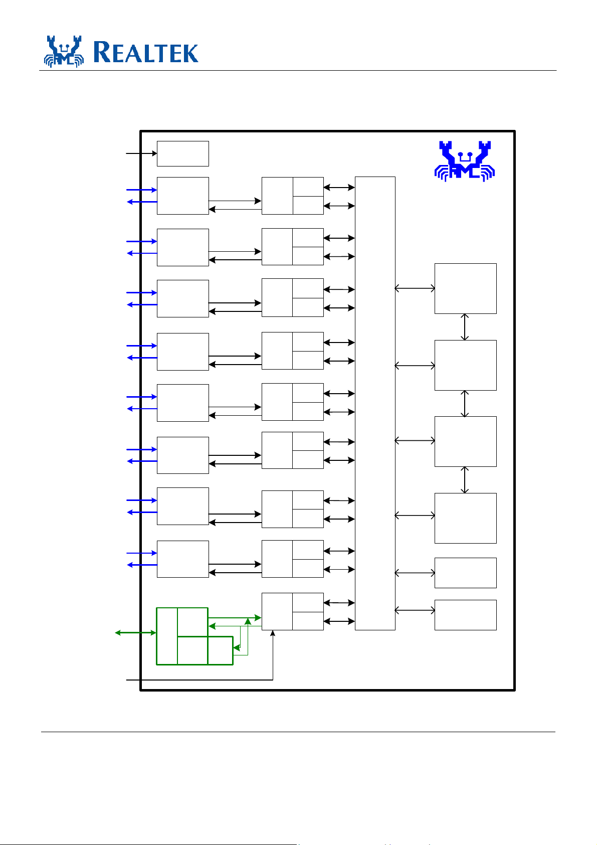
3. Block Diagram
RTL8309SB
Datasheet
IBREF
RX+-[0]
TX+-[0]
RX+-[1]
TX+-[1]
RX+-[2]
TX+-[2]
RX+-[3]
TX+-[3]
RX+-[4]
TX+-[4]
RX+-[5]
TX+-[5]
Wave form
Shapi ng
10Base-T or
100Base -TX
PHYcei ver
10Base-T or
100Base -TX
PHYcei ver
10Base-T or
100Base -TX
PHYcei ver
10Base-T or
100Base -TX
PHYcei ver
10Base-T or
100Base -TX
PHYcei ver
10Base-T or
100Base -TX
PHYcei ver
10/100
MAC 0
10/100
MAC 1
10/100
MAC 2
10/100
MAC 3
10/100
MAC 4
10/100
MAC 5
Flow
Control
TX/RX
FIFO
Flow
Control
TX/RX
FIFO
Flow
Control
TX/RX
FIFO
Flow
Control
TX/RX
FIFO
Flow
Control
TX/RX
FIFO
Flow
Control
TX/RX
FIFO
RTL8309S B
Look-up Table
(1024-entries)
Swi tch Fabric, VLAN, QoS, Trunking
Queue
Management
Buffer
Management
RX+-[6]
TX+-[6]
RX+-[7]
TX+-[7]
MII
Signal
P8MODE[1:0]
13
10Base-T or
100Base -TX
PHYcei ver
10Base-T or
100Base -TX
PHYcei ver
MAC
Mode
/
Inter
face
PHY
Mode
Mode
Select
10/100
MAC 6
10/100
MAC 7
10/100
MAC 8
Flow
Control
TX/RX
FIFO
Flow
Control
TX/RX
FIFO
Flow
Control
TX/RX
FIFO
Packet Buffer
EEPROM
Interface
Control
Registers
Figure 1. Block Diagram
Single-chip 9-port 10/100Mbps Switch Controller 4 Track ID: JATR-1076-21 Rev. 1.4
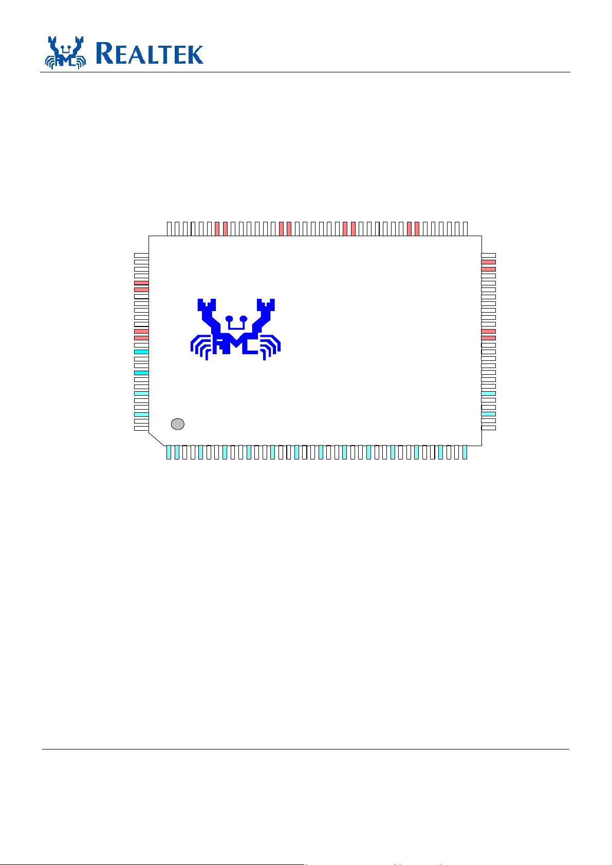
4. Pin Assignments
P3_LED[1]/Dis_Trunk
P3_LED[0]/LED_MODE[2]
P2_LED[3]/LED_MODE[1]
P2_LED[2]/LED_MODE[0]
P2_LED[1]/MII_MODE[1]
En_AutoXover/P1_LED[3]
En_ANEG/P1_LED[2]
En_FCTRL/P1_LED[1]
En_BKPRS/P1_LED[0]
Force_Duplex/P0_LED[3]
Force_Speed/P0_LED[2]
En_BRD_CTRL/P0_LED[1]
En_RST_BLNK/P0_LED[0]
EnEEPROM/LoopLED#
VDDD
VSSD
VDDD
VSSD
Test pin
VSSPLL
VDDPLL
Test Pin
IBREF
VDDA
TXON[0]
TXOP[0]
VSSA
RXIP[0]
RXIN[0]
P2_LED[0]/MII_MODE[0]
102
103
104
105
106
107
108
109
110
111
112
113
114
115
116
117
X1
X2
118
119
120
121
122
123
124
125
126
127
128
1
989799
101
100
2
P3_LED[2]/En_Forward
VSSD
VDDD
949693
9876543
P4_LED[1]/En_Agrs_Back
P4_LED[2]/Max_Pkt_Len
P4_LED[0]/En_48pass1
P3_LED[3]/En_Defer
90
919592
12
13
10
11
P5_LED[3]/Dis_DS_Pri
P6_LED[0]/QWeight[0]
VSSD
VDDD
VSSD
P4_LED[3]/Max_Pause_Count
89
P5_LED[1]/Sel_PortPri[1]
P5_LED[0]/Sel_PortPri[0]
868587
88
P6_LED[1]/QWeight[1]
P5_LED[2]/Dis_VLAN_Pri
828481
VDDD
798380
P6_LED[3]/Dis_LeakyVLAN
P6_LED[2]/Dis_VLAN
78
77
RTL8309SB
22
21
20
19
18
17
16
15
14
23
26
25
24
P7_LED[0]/Dis_ARPVLAN
76
27
P7_LED[1]/LED_BLNK_TIME
28
P7_LED[3]/Dis_FC_AutoOff
P7_LED[2]/Port_LED_LOC
747375
30
29
RTL8309SB
Datasheet
VSSD
VDDD
MRXD[2]/PTXD[2]
MRXD[3]/PTXD[3]
707269
343837
33
32
31
MRXC/PTXC
MRXD[0]/PTXD[0]
MRXDV/PTXEN
MRXD[1]/PTXD[1]
677168
66
65
64
63
62
61
60
59
58
57
56
55
54
53
52
51
50
49
48
47
46
45
44
43
42
41
40
39
36
35
MCOL/PCOL
VSSIO
VDDIO
MTXD[3]/PRXD[3]
MTXD[2]/PRXD[2]
MTXD[1]/PRXD[1]
MTXD[0]/PRXD[0]
MTXEN/PRXDV
MTXC/PRXC
SDA_MDIO
SCL_MDC
VSSD
VDDD
MII_LNK_STA#
MII_DUP_STA
MII_SPD_STA
MII_FCTRL_STA
RESET#
NC
Test Pin
VDDA
TXON[7]
TXOP[7]
VSSA
RXIP[7]
RXIN[7]
VDDA
VSSA
VDDA
VSSA
RXIP[2]
RXIN[2]
TXOP[2]
TXON[2]
VSSA
RXIP[1]
RXIN[1]
TXOP[1]
TXON[1]
VDDA
VSSA
RXIP[3]
RXIN[3]
TXOP[3]
TXON[3]
VDDA
VSSA
RXIP[4]
RXIN[4]
TXOP[4]
TXON[4]
VDDA
VSSA
RXIP[5]
RXIN[5]
TXOP[5]
TXON[5]
VDDA
VSSA
RXIP[6]
RXIN[6]
VDDA
TXOP[6]
TXON[6]
Figure 2. Pin Assignments
Single-chip 9-port 10/100Mbps Switch Controller 5 Track ID: JATR-1076-21 Rev. 1.4

RTL8309SB
Datasheet
Codes used in the following tables: ‘A’ stands for analog; ‘D’ stands for digital, ‘I’ stands for input; ‘O’ stands for output.
Table 1. Pin Assignments
Name Pin No. Type Name Pin No Type
VDDA,
VSSA,
TXON[1],
TXOP[1],
VSSA,
RXIP[1],
RXIN[1],
VDDA,
RXIN[2],
RXIP[2],
VSSA,
TXOP[2],
TXON[2],
VDDA,
TXON[3],
TXOP[3],
VSSA,
RXIP[3],
RXIN[3],
VDDA,
RXIN[4],
RXIP[4],
VSSA,
TXOP[4],
TXON[4],
VDDA,
TXON[5],
TXOP[5],
VSSA,
RXIP[5],
RXIN[5],
VDDA,
RXIN[6],
RXIP[6],
VSSA,
TXOP[6],
TXON[6],
VDDA,
RXIN[7],
RXIP[7],
VSSA,
TXOP[7],
TXON[7],
VDDA,
NC,
NC
RESET#
MII_FCTRL_STA,
MII_SPD_STA,
MII_DUP_STA,
MII_LNK_STA#,
VDDD,
VSSD,
SCL_MDC,
SDA_MDIO,
MTXC/PRXC,
MTXEN/PRXDV,
MTXD[0]/PRXD[0],
MTXD[1]/PRXD[1],
MTXD[2]/PRXD[2],
MTXD[3]/PRXD[3],
VDDIO,
VSSIO,
MCOL/PCOL
1,
2,
3,
4,
5,
6,
7,
8,
9,
10,
11,
12,
13,
14,
15,
16,
17,
18,
19,
20,
21,
22,
23,
24,
25,
26,
27,
28,
29,
30,
31,
32,
33,
34,
35,
36,
37,
38,
39,
40,
41,
42,
43,
44,
45,
46,
47,
48,
49,
50,
51,
52,
53,
54,
55,
56,
57,
58,
59,
60,
61,
62,
63,
64
AVDD
AGND
AO
AO
AGND
AI
AI
AVDD
AI
AI
AGND
AO
AO
AVDD
AO
AO
AGND
AI
AI
AVDD
AI
AI
AGND
AO
AO
AVDD
AO
AO
AGND
AI
AI
AVDD
AI
AI
AGND
AO
AO
AVDD
AI
AI
AGND
AO
AO
AVDD
I
I
I
I
I
DVDD
DGND
I/O
I/O
I/O
O
I/O
I/O
I/O
I/O
DVDD
DGND
I/O
MRXC / PTXC
MRXDV / PTXDV,
MRXD[0] / PTXD[0],
MRXD[1] / PTXD[1],
MRXD[2] / PTXD[2],
MRXD[3] / PTXD[3],
VDDD,
VSSD,
P7_LED[3] / Dis_FC_AutoOff,
P7_LED[2] / Port_LED_LOC,
P7_LED[1] / LED_BLNK_TIME,
P7_LED[0] / Dis_ARPVLAN,
P6_LED[3] / Dis_LeakyVLAN,
P6_LED[2] / Dis_VLAN,
VDDD,
VSSD,
P6_LED[1] / QWeight[1],
P6_LED[0] / QWeight[0],
P5_LED[3] / Dis_DS_Pri,
P5_LED[2] / Dis_VLAN_Pri,
P5_LED[1] / Sel_PortPri[1],
P5_LED[0] / Sel_PortPri[0],
VDDD,
VSSD,
P4_LED[3] / Max_Pause_Count,
P4_LED[2] / Max_Pkt_Len,
P4_LED[1] / En_Agrs_Back,
P4_LED[0] / En_48pass1,
P3_LED[3] / En_Defer,
P3_LED[2] / En_Forward,
VDDD,
VSSD
P3_LED[1] / Dis_Trunk,
P3_LED[0] / LED_MODE[2],
P2_LED[3] / LED_MODE[1],
P2_LED[2] / LED_MODE[0],
P2_LED[1] / MII_MODE[1],
P2_LED[0] / MII_MODE[0],
P1_LED[3] / En_AutoXover,
P1_LED[2] / En_ANEG,
P1_LED[1] / En_FCTRL
P1_LED[0] / En_BKPRS,
VDDD,
VSSD
P0_LED[3] / Force_Duplex,
P0_LED[2] / Force_Speed,
P0_LED[1] / En_BRD_CTRL,
P0_LED[0] / En_RST_BLNK,
LoopLED#,/EnEEPROM
VDDD,
VSSD,
NC,
VSSPLL,
X1,
X2,
VDDPLL,
NC,
IBREF,
VDDA,
TXON[0],
TXOP[0],
VSSA,
RXIP[0],
RXIN[0],
65,
66,
67,
68,
69,
70,
71,
72,
73,
74,
75,
76,
77,
78,
79
80,
81,
82,
83,
84,
85,
86,
87,
88,
89,
90,
91,
92,
93,
94,
95,
96,
97,
98,
99,
100,
101,
102,
103,
104,
105,
106,
107,
108,
109,
110,
111,
112,
113,
114,
115,
116,
117,
118,
119,
120,
121,
122,
123,
124,
125,
126,
127,
128
I/O
I
I
I
I
I
DVDD
DGND
I/O
I/O
I/O
I/O
I/O
I/O
DVDD
DGND
I/O
I/O
I/O
I/O
I/O
I/O
DVDD
DGND
I/O
I/O
I/O
I/O
I/O
I/O
DVDD
DGND
I/O
I/O
I/O
I/O
I/O
I/O
I/O
I/O
I/O
I/O
DVDD
DGND
I/O
I/O
I/O
I/O
I/O
DVDD
DGND
AGND
I
O
AVDD
AO
AVDD
AO
AO
AGND
AI
AI
Single-chip 9-port 10/100Mbps Switch Controller 6 Track ID: JATR-1076-21 Rev. 1.4
RTL8309SB
Datasheet
5. Pin Descriptions
“Type” codes used in the following tables: ‘A’ stands for analog; ‘D’ stands for digital, ‘I’ stands for input; ‘O’ stands for
output, ‘Ipu’ stands for input with internal pull-up.
Upon reset: defined as a short time after the end of a hardware reset. After reset: defined as the time after the specified “Upon
Reset” time.
5.1.
Pin Name Pin No. Type Description Default
RXIP[7:0]
RXIN[7:0]
TXOP[7:0]
TXON[7:0]
5.2.
Media Connection Pins
Table 2. Media Connection Pins
40, 34,
30, 22,
18, 10,
6, 127,
39, 33,
31, 21,
19, 9,
7, 128
42, 36,
28, 24,
16, 12,
4, 125,
43, 37,
27, 25,
15, 13,
3, 124
AI Differential Receive Data Input shared by 100Base-TX, 10Base-T for
connection to a transformer.
AO Differential Transmit Data Output shared by 100Base-TX, 10Base-T
for connection to a transformer.
MII Port MAC Interface Pins
The external device can be either 2.5V or 3.3V compatible depending on the power supplied to VDDIO. The input and
input/output pins listed below do not implement an internal pull-high resistor. An external pull-high resistor is required for
these floating input pins to reduce power consumption.
Table 3. MII Port MAC Interface Pins
Pin Name Pin No. Type Description Default
MRXD[3:0]
/PTXD[3:0]
MRXDV/PTXEN 66 I For MII MAC mode, this pin represents MRXDV, MII receive data
Single-chip 9-port 10/100Mbps Switch Controller 7 Track ID: JATR-1076-21 Rev. 1.4
70, 69,
68, 67
I For MII MAC mode, these pins are MRXD[3:0], MII receive data
nibble.
For MII PHY mode, these pins are PTXD[3:0], MII transmit data
nibble.
For SNI PHY mode, PTXD[0] is serial transmit data.
valid.
For MII PHY mode, this pin represents PTXEN, MII transmit enable.
For SNI PHY mode, this pin represents PTXEN, transmit enable.

RTL8309SB
Datasheet
Pin Name Pin No. Type Description Default
MRXC/PTXC 65 I/O For MII MAC mode, this pin represents MRXC/MII receive clock (acts
as input).
For MII/SNI PHY mode, this pin represent PTXC/MII transmit clock
(acts as output).
MCOL/PCOL 64 I/O For MII MAC mode, this pin represents MCOL, MII collision detect
(acts as input).
For MII/SNI PHY mode, this pin represents PCOL, MII collision detect
(acts as output).
MTXD[3:0]
/PRXD[3:0]
MTXEN/PRXDV 57 O For MII MAC mode, this pin represents MTXEN, MII transmit enable.
MTXC/PRXC 56 I/O For MII MAC mode, this pin represents MTXC, MII transmit clock
MII_MODE[1:0]
/P2_LED[1:0]
MII_LNK_STA# 51 Ipu Provides MII port (9th port) Link Status for MAC module at MII
MII_DUP_STA 50 Ipu Provides MII port (9th port) duplex status for MAC module at MII
MII_SPD_STA 49 Ipu Provides MII port (9th port) speed status for MAC module at MII
MII_FCTRL_STA 48 Ipu Provides MII port (9th port) flow control status for MAC module at MII
61, 60,
59, 58
101,
102
O Output after reset.
For MII MAC mode, these pins are MTXD[3:0], MII transmit data of
MAC.
For MII PHY mode, these pins are PRXD[3:0], MII receive data of
MAC.
For SNI PHY mode, PRXD[0] is SNI serial receive data. PRXD[3:1]
are unused.
For MII PHY mode, this pin represents PRXDV, MII receive data valid.
For SNI PHY mode, this pin represents PRXDV, SNI receive data
valid.
(acts as input).
For MII/SNI PHY mode, this pin represents MRXC, MII/SNI receive
clock (acts as output).
Ipu Input upon reset = Select MII port (9th port) operating mode.
11=Tristate MII output.
10=MII MAC mode.
01=MII PHY mode.
00=SNI PHY mode.
MAC/MII PHY/SNI PHY operation mode in real time.
This pin sets the link status of the MII port MAC module in real-time.
MAC/MII PHY/SNI PHY operation mode in real time.
1: MII port operates in full duplex mode
0: MII port operates in half duplex mode
MAC/MII PHY/SNI PHY operation mode in real time.
1: MII port operates at 100Mbps speed
0: MII port operates at 10Mbps speed
In an application outlined below, this pin should be left floating:
For HomePNA (MII MAC mode), speed is determined by RXC and
TXC from PHY of HomePNA running at 1Mbps.
For SNI PHY mode, speed is fixed at 10MHz clock rate.
MAC/MII PHY/SNI PHY operation mode in real time.
1: MII port has flow control ability
0: MII port does not have flow control ability
11
1
1
1
1
Single-chip 9-port 10/100Mbps Switch Controller 8 Track ID: JATR-1076-21 Rev. 1.4
RTL8309SB
Datasheet
5.3.
Pin Name Pin No. Type Description Default
X1 118 I 25MHz crystal input.
X2 119 O 25MHz crystal output.
RESET# 47 I Active low reset signal.
IBREF 122 A Control transmit output waveform Vpp.
NC 45, 46,
5.4.
Each port supports four LED pins for status indication. The indicated status of these four LED pins may be changed by setting
different values for strapping pin LED_MODE[2:0].
Note 1: All LED statuses are represented as active-low or high depending on input strapping, except Bi-color Link/Act in
Miscellaneous Pins
The clock tolerance is +-50ppm.
To complete the reset function, this pin must be asserted for at least
10ms. After reset, about 30ms is needed for the RTL8309SB to
complete the internal test function and initialization.
Note: This pin is a Schmitt input pin.
This pin should be grounded through a 2.0K ohm resistor.
Not Connected – Floating in normal operation.
116, 121
Port LED Pins
Table 4. Miscellaneous Pins
Bi-color LED mode, whose polarity depends on Bi-color Speed status.
Note 2: Those pins are dual function pins: output for LED and input for strapping.
Table 5. Port LED Pins
Pin Name Pin No. Type Description Default
P0_LED[0]
P1_LED[0]
P2_LED[0]
P3_LED[0]
P4_LED[0]
P5_LED[0]
P6_LED[0]
P7_LED[0]
112, 106,
102, 98,
92, 86,
82, 76
Ipu/O
Output after reset = used for the 1st LED.
Mode 7: Speed (On =100 Mbps, Off =10Mbps)
Mode 6: Activity (Flash=Tx or Rx activity)
Mode 5: Speed (On =100 Mbps, Off =10Mbps)
Mode 4: Collision (Flash=Collision)
Mode 3: Reserved for internal use
Mode 2: RxAct+10/100 (Flash every 120ms=10Mbps Rx activity,
Flash every 43ms = 100Mbps Rx activity).
Mode 1: Duplex+Collision (On=Full, Off=Half with no collision,
Flash = Collision)
Mode 0: Bi-color Speed. Polarity depends on Bi-color Link+Activity
LED status. Refer to section 8.3.17 LEDs, page 87, for detailed
information.
1
1
1
1
1
1
1
1
Single-chip 9-port 10/100Mbps Switch Controller 9 Track ID: JATR-1076-21 Rev. 1.4

RTL8309SB
Datasheet
Pin Name Pin No. Type Description Default
P0_LED[1]
P1_LED[1]
P2_LED[1]
P3_LED[1]
P4_LED[1]
P5_LED[1]
P6_LED[1]
P7_LED[1]
P0_LED[2]
P1_LED[2]
P2_LED[2]
P3_LED[2]
P4_LED[2]
P5_LED[2]
P6_LED[2]
P7_LED[2]
P0_LED[3]
P1_LED[3]
P2_LED[3]
P3_LED[3]
P4_LED[3]
P5_LED[3]
P6_LED[3]
P7_LED[3]
LED_MODE[2]
/P3_LED[0]
LED_MODE[1]
/P2_LED[3]
LED_MODE[0]
/P2_LED[2]
111, 105,
101, 97,
91, 85,
81, 75
110, 104,
100, 94,
90, 84,
78, 74,
109, 103,
99, 93,
89, 83,
77, 73
98,
99,
100
Ipu/O
Ipu/O
Ipu/O
Output after reset = used for the 2nd LED.
Mode 7: Duplex+Collision (On=Full, Off=Half with no collision,
Flash = Collision)
Mode 6: Speed (On =100 Mbps, Off =10Mbps)
Mode 5: Duplex (On=Full, Off=Half)
Mode 4: Duplex (On=Full, Off=Half)
Mode 3: Duplex+Collision (On=Full, Off=Half with no collision,
Flash = Collision)
Mode 2: TxAct+10/100 (Flash every 120ms = 10Mbps Tx activity,
Flash every 43ms = 100Mbps Tx activity)
Mode 1: 10Link+Act (On=Link on 10Mbps, Off=No link on
10Mbps, Flash=10Mbps Tx or Rx activity)
Mode 0: Duplex+Collision (On=Full, Off=Half with no collision,
Flash = Collision)
Output after reset = used for the 3rd LED.
Mode 7: Link+Act (On=Link, Off=No link, Flash=Tx or Rx activity)
Mode 6: Link (On=Link, Off=No link)
Mode 5: Link+Act (On=Link, Off=No link, Flash=Tx or Rx activity)
Mode 4: Link+Act+Speed (On=Link, Off=No link, Flash every
120ms=10Mbps activity, flash every 43ms=100Mbps)
Mode 3: Link+Act+Speed (On=Link, Off=No link, Flash every
120ms=10Mbps activity, flash every 43ms=100Mbps)
Mode 2: Link (On=Link, Off=No link)
Mode 1: 100Link+Act (On=Link on 100Mbps, Off=No link on
100Mbps, Flash=100Mbps Tx or Rx activity)
Mode 0: Bi-color Speed. Polarity depends on Bi-color Link+Activity
LED status. Refer to section 8.3.17 LEDs, page 87, for detailed
information.
Output after reset = used for the 4th LED.
Mode 7: Reserved for internal use
Mode 6: Reserved for internal use
Mode 5: Reserved for internal use
Mode 4: Reserved for internal use
Mode 3: 10/100 (On =100 Mbps, Off =10Mbps)
Mode 2: Reserved for internal use
Mode 1: Reserved for internal use
Mode 0: Reserved for internal use
I/O Input upon reset = Select LED display mode upon reset.
LED_MODE[2:0]=111 -> Mode 7:
Speed, Duplex+Collision, Link+Act, Reserved
LED_MODE[2:0]=110 -> Mode 6:
Activity, Speed, Link, Reserved
LED_MODE[2:0]=101 -> Mode 5:
Speed, Duplex, Link+Act, Reserved
LED_MODE[2:0]=100 -> Mode 4:
Collision, Duplex, Link+Act+Speed, Reserved
LED_MODE[2:0]=011 -> Mode 3:
Reserved, Duplex+Collision, Link+Act+Speed, 10/100
LED_MODE[2:0]=010 -> Mode 2:
RxAct+10/100, TxAct+10/100, Link, Reserved
LED_MODE[2:0]=001 -> Mode 1:
Duplex+Collision, 10Link+Act, 100Link+Act, Reserved.
LEDM_ODE[2:0]=000 -> Mode 0:
Bi-color Speed, Duplex+Collision, Bi-color Link+Act, Reserved
1
1
1
1
1
1
1
1
1
1
1
1
1
1
1
1
1
1
1
1
1
1
1
1
111
Single-chip 9-port 10/100Mbps Switch Controller 10 Track ID: JATR-1076-21 Rev. 1.4
RTL8309SB
Datasheet
Pin Name Pin No. Type Description Default
Port_LED_LOC
/P7_LED[2]
LoopLED#
/EnEEPROM
74
113
Ipu/O
Ipu/O
Input upon reset = Per port LED pin location reversed.
1: For designs where LEDs are placed at the opposite side to the
phone jack
Port 0 LEDs are assigned at pins 109~112
Port 1 LEDs are assigned at pins 103~106
Port 2 LEDs are assigned at pins 99~102
Port 3 LEDs are assigned at pins 93, 94, 97, 98
Port 4 LEDs are assigned at pins 89~92
Port 5 LEDs are assigned at pins 83~86
Port 6 LEDs are assigned at pins 77, 78, 80, 81
Port 7 LEDs are assigned at pins 73~76
0: Suitable for designs where LEDs are placed on the same side as
the phone jack
Port 0 LEDs are assigned at pins 73~76
Port 1 LEDs are assigned at pins 77, 78, 80, 81
Port 2 LEDs are assigned at pins 83~86
Port 3 LEDs are assigned at pins 89~92
Port 4 LEDs are assigned at pins 93, 94, 97, 98
Port 5 LEDs are assigned at pins 99~102
Port 6 LEDs are assigned at pins 103~106
Port 7 LEDs are assigned at pins 109~112
Output after reset = LoopLED# used for LED.
If Loop detection is enabled, this pin indicates whether a Network
loop is detected or not. Otherwise, this pin has no function.
Note: The LED statuses are represented as active-low or high
depending on input strapping.
=> If Input=1: Output 0=Network loop is detected. 1=No loop.
=> If Input=0: Output 1=Network loop is detected. 0= No loop.
1
1
5.5.
Pin Name Pin No. Type Description Default
EnEEPROM
/LoopLED#
SCL_MDC 54 I/O EEPROM Serial Clock or MDC.
Single-chip 9-port 10/100Mbps Switch Controller 11 Track ID: JATR-1076-21 Rev. 1.4
Serial EEPROM and SMI Pins
Table 6. Serial EEPROM and SMI Pins
113 Ipu/O Input upon reset = Enable loading of serial EEPROM upon reset.
1: Enable Serial EEPROM load upon reset
0: Disable Serial EEPROM load upon reset
This pin is three state when pin RESET#=0.
When the RTL8309SB detects an EEPROM connected to it, this pin
becomes SCL (output) to load the serial EEPROM upon reset. Then
the pin changes to MDC (input) after reset. In this case, this pin
should be pulled high (VDDIO 2.5V/3.3V) by external register.
When the RTL8309SB does not detect an EEPROM connected to it,
this pin is MDC (input). In this case, it needs an external pull-high
resistor, unless it is floated.
1
-

RTL8309SB
Datasheet
Pin Name Pin No. Type Description Default
SDA_MDIO 55 I/O EEPROM Serial Data Input/Output or MDIO.
This pin is three state when pin RESET#=0.
When the RTL8309SB detects an EEPROM connected to it, this pin
becomes SDA (input/output) to load the serial EEPROM upon reset.
The pin changes to MDIO (input/output) after reset.
When the RTL8309SB does not detect an EEPROM connected to it,
this pin is MDIO (input/output). It should be pulled high by an
external resistor.
-
5.6.
Note: All strapping pins are dual function pins: output for LED and input for strapping. The table below covers strapping only.
See Port LED Pins, on page 9, for LED pin settings.
Pin Name Pin No. Type Description Default
En_ANEG
/P1_LED[2]
En_FCTRL
/P1_LED[1]
En_BKPRS
/P1_LED[0]
Force_Duplex
/P0_LED[3]
Force_Speed
/P0_LED[2]
Strapping Pins
104
105
106
109
110
Table 7. Strapping Pins
Input upon reset = Enable Auto-negotiation function.
Ipu
1: Enable the auto-negotiation function (NWay mode) and set PHY
register 0.12
0: Disable the auto-negotiation function (force mode) and deselect
PHY register 0.12
Output after reset = used for LED.
Input upon reset = Enable flow control ability in full duplex mode.
Ipu
1: In NWay mode, this pin sets PHY register 4.10, but the flow
control function is finally enabled based on the auto negotiation
result. In force mode, this pin will always enable the flow control
function
0: Disable the flow control function
Output after reset = used for LED.
Input upon reset = Enable backpressure ability in half duplex mode.
Ipu
1: Enable backpressure
0: Disable backpressure
Output after reset = used for LED.
Force duplex mode.
Ipu
This pin sets PHY Reg.0.8 and influences the contents of PHY
Reg.4.
1: Force full duplex if auto-negotiation is disabled
0: Force half duplex if auto-negotiation is disabled
Output after reset = used for LED.
Force operating speed.
Ipu
This pin sets PHY Reg.0.13 and influences the contents of PHY
Reg.4.
1: Force 100Mbps speed if auto-negotiation is disabled
0: Force 10Mbps speed if auto-negotiation is disabled
Output after reset = used for LED.
1
1
1
1
1
Single-chip 9-port 10/100Mbps Switch Controller 12 Track ID: JATR-1076-21 Rev. 1.4

RTL8309SB
Datasheet
Pin Name Pin No. Type Description Default
En_BRD_CTRL
/P0_LED[1]
En_RST_BLNK
/P0_LED[0]
En_AutoXover
/P1_LED[3]
Dis_FC_AtuoOff
/P7_LED[3]
En_Forward
/P3_LED[2]
En_Defer
/P3_LED[3]
En_48pass1
/P4_LED[0]
En_Agrs_Back
/P4_LED[1]
111
112
103
73
94
93
92
91
Input upon reset = Disable Broadcast Storm Control.
Ipu
1: Disable Broadcast Storm Control
0: Enable Broadcast Storm Control
Output after reset = used for LED.
Input upon reset = Enable blinking of LEDs upon reset.
Ipu
1: Enable power-on LED blinking for diagnosis
0: Disable power-on LED blinking
Output after reset = used for LED.
Input upon reset = Enable Auto crossover detection.
Ipu
1: Enable auto crossover detection
0: Disable auto crossover detection. MDI only
Output after reset = used for LED.
Disable auto turn off of flow control ability.
Ipu
1: Disable
0: Enable auto turn off flow control ability on the low priority queue
for 1~2 seconds whenever the port receives a high priority frame.
The flow control ability will be re-enabled if this port does not
receive another high priority frame during this 1~2 second duration
Output after reset = used for LED.
Input upon reset = Enable forwarding of 802.1D specified reserved
Ipu
group MAC address frames.
1: Forward reserved control packets with DID=01-80-C2-00-00-03
to 01-80-C2-00-00-0F
0: Filter reserved control packets with DID=01-80-C2-00-00-03 to
01-80-C2-00-00-0F
Output after reset = used for LED.
Input upon reset = Enable carrier sense defering function.
Ipu
1: Enable carrier sense deferring function for half duplex
backpressure
0: Disable carrier sense deferring function for half duplex
backpressure
Output after reset = used for LED.
Enable 48 pass 1 mechanism.
Ipu
1: 48 pass 1. Continuously collides 48 input packets then passes 1
packet to retain system resources and avoid repeater partition when
buffer is full
0: Continuously collides input packets to avoid packet loss when
buffer is full
Output after reset = used for LED.
Input upon reset = Enable aggressive back-off mechanism.
Ipu
1: Enable more aggressive back-off mechanism in half duplex mode
for performance enhancement. The back-off limitation will become 3
in this mode (default is 10)
0: Disable aggressive back-off mechanism in half duplex mode
Output after reset = used for LED.
1
1
1
1
1
1
1
1
Single-chip 9-port 10/100Mbps Switch Controller 13 Track ID: JATR-1076-21 Rev. 1.4

RTL8309SB
Datasheet
Pin Name Pin No. Type Description Default
Max_Pkt_Len
/P4_LED[2]
Max_Pause_Count
/P4_LED[3]
Dis_Trunk
/P3_LED[1]
Sel_PortPri[1:0]
/P5_LED[1:0]
Dis_VLAN_Pri
/P5_LED[2]
Dis_DS_Pri
/P5_LED[3]
QWeight[1:0]
/P6_LED[1:0]
90
89
97
85, 86
84
83
81, 82
Input upon reset = Select maximum frame length.
Ipu
1: 1536 bytes
0: 1552 bytes
Output after reset = used for LED.
Input upon reset = Select the max Pause frame count during a
Ipu
congested event.
1: Generates maximum of 32 pause frames, even if congestion still
exists
0: Continuously generates pause frames until congestion is resolved
Output after reset = used for LED.
Disable Two Port Trunking function.
Ipu
1: Disable two port trunking function
0: Port 0 and port 1 are combined as one trunk
Output after reset = used for LED.
Input upon reset = Select high priority port for port-based priority
Ipu
QoS.
11: Disable port-based priority function
10: Select port 0 as high priority port
01: Select port 2 as high priority port
00: Select port 3 as high priority port
Output after reset = used for LED.
Input upon reset = Disable 802.1p VLAN tag priority based QoS.
Ipu
1: Disable 802.1p priority classification for ingress packets on each
port
0: Enable 802.1p priority classification for ingress packets on each
port. A User priority field in the VLAN tag greater or equal to 4 will
be considered a high priority packet
Output after reset = used for LED.
Input upon reset = Disable Diffserv priority based QoS.
Ipu
1: Disable diffserv priority classification for ingress packets on each
port
0: Enable diffserv priority classification for ingress packets on each
port
Output after reset = used for LED.
Input upon reset = Weighted round robin ratio priority queue.
Ipu
The frame service ratio between the high priority queue and low
priority queue is:
11=16:1
10=Always high priority queue first
01=8:1
00=4:1
Output after reset = used for LED.
1
1
1
1
1
1
1
Single-chip 9-port 10/100Mbps Switch Controller 14 Track ID: JATR-1076-21 Rev. 1.4

RTL8309SB
Datasheet
Pin Name Pin No. Type Description Default
Dis_VLAN
/P6_LED[2]
Dis_LeakyVLAN
/P6_LED[3]
Dis_ARPVLAN
/P7_LED[0]
LED_BLNK_TIME
/P7_LED[1]
78
77
76
75
Input upon reset = Disable VLAN.
Ipu
1: Disable VLAN
0: Enable VLAN. The default VLAN membership configuration is
MII port overlapped with all the other ports to form 8 individual
VLANs. The default membership configuration may be modified by
setting internal registers via the SMI interface or EEPROM
Output after reset = used for LED.
Input upon reset = Disable Leaky VLAN.
Ipu
1: Disable forwarding of unicast frames to other VLANs
0: Enable forwarding of unicast frames to other VLANs
Note: Broadcast and multicast frames adhere to the VLAN
configuration.
Output after reset = used for LED.
Input upon reset = Disable ARP broadcast to all VLANs.
Ipu
1: Disable broadcast of ARP broadcast packets to all VLANs
0: Enable broadcast of ARP broadcast packets to all VLANs
Output after reset = used for LED.
Input upon reset = Select blinking speed of activity and collision
Ipu
LED.
1: On 43ms then Off 43ms
0: On 120ms then Off 120ms
Note: This pin only af fect s LE Ds that are configured in LED mode 1,
5, and 7.
Output after reset = used for LED.
1
1
1
1
Single-chip 9-port 10/100Mbps Switch Controller 15 Track ID: JATR-1076-21 Rev. 1.4

RTL8309SB
Datasheet
5.7.
Pin Name Pin No. Type Description Default
VDDD 52, 71,
VSSD 53, 72,
VDDIO 62 P 2.5/3.3V digital VDD for MII interface.
VSSIO 63 G Digital ground for MII interface.
VDDPLL 120 P 1.8V analog power for PLL.
VSSPLL 117 G 1.8V analog ground for PLL.
VDDA 1, 8,
VSSA 2, 5,
Power Pins
Table 8. Power Pins
P 1.8V digital power.
79, 87,
95,107,
114
G Digital ground.
80, 88,
96, 108,
115
P 1.8V analog power (Used for transmitters and equalizers).
14, 20,
26, 32,
38, 44,
123
G Analog ground.
11, 17,
23, 29,
35, 41,
126
Single-chip 9-port 10/100Mbps Switch Controller 16 Track ID: JATR-1076-21 Rev. 1.4

6. EEPROM Register Description
RTL8309SB
Datasheet
6.1.
Global Control Registers
6.1.1. Global Control Register0
Table 9. Global Control Register0
Name Byte.bit Description Default
EEPROM
existence
Accept Error
disable
IEEE 802.3x
transmit flow
control enable
IEEE 802.3x
receive flow
control enable
Broadcast input
or output drop
Aging enable 0.2 1: Enable aging function in the switch
Fast aging enable 0.1 1: An entry learned in the lookup table will be aged out if it is not updated
Enable ISP MAC
Address
Translation
0.7 1: EEPROM does not exist
0: EEPROM exists
0.6 1: Filter bad packets in normal operation
0: Switch all packets including bad ones
0.5 1: Invoke transmit flow control based on auto-negotiation result
0: Switch will not enable transmit flow control
0.4 1: When the switch receives a pause control frame, it has the ability to stop
the next transmission of a normal frame until the timer has expired based
on the auto negotiation result
0: Receive flow control not enabled
0.3 1: Broadcast input drop is selected
0: Broadcast output drop is selected
0: Disable aging function in the switch
within an 800µs period
0: Disable fast aging function. The normal aging time of the RTL8309SB is
around 200~300 seconds
0.0 1: Enable ISP MAC Address Translation
0: Disable ISP MAC Address Translation
0
1
1
1
1
1
0
0
6.1.2. Global Control Register1
Table 10. Global Control Register1
Name Byte.bit Description Default
LED Mode 1.7~1.5 111 -> Mode 7: Speed, Duplex+Collision, Link+Act, SQI
110 -> Mode 6: Activity, Speed, Link, SQI
101 -> Mode 5: Speed, Duplex, Link+Act, SQI
100 -> Mode 4: Collision, Duplex, Link+Act+Speed, SQI
011 -> Mode 3: SQI, Duplex+Collision, Link+Act+Speed,10/100
010 -> Mode 2: RxAct+10/100, TxAct+10/100, Link, SQI
001 -> Mode 1: Duplex+Collision, 10Link+Act, 100Link+Act, SQI
000 -> Mode 0: Duplex+Collision, Bi-color Speed, Bi-color Link+Act, SQI
Reserved 1.4 1
Disable VLAN 1.3 1: Disable VLAN
0: Enable VLAN
Disable 802.1Q
tag aware VLAN
Single-chip 9-port 10/100Mbps Switch Controller 17 Track ID: JATR-1076-21 Rev. 1.4
1.2 1: Disable the 802.1Q tagged-VID Aware function
0: Use tagged-VID VLAN mapping for tagged frames but still use
Port-Based VLAN mapping for priority-tagged and untagged frame
111
1
0

RTL8309SB
Datasheet
Name Byte.bit Description Default
Disable VLAN
member set
ingress filtering
Disable VLAN
tag admit control
1.1 1: The switch will not drop the received frame if the ingress port of this
packet is not included in the matched VLAN member set
0: The switch will drop the received frame if the ingress port of this packet
is not included in the matched VLAN member set
1.0 1: The switch accepts all frames received
0: The switch will only accept tagged frames and will drop untagged
frames
1
1
6.1.3. Global Control Register2
Table 11. Global Control Register2
Name Byte.bit Description Default
Enable default
high priority
DiffServ code
point
Reserved 2.6~2.0 1111
2.7 1: The default DiffServ code point listed below will be considered a high
priority code point if DiffServ priority function is enabled
EF – 101110
AF – 001010, 010010, 011010, 100010
Network Control – 111000, 110000
0: The default DiffServ code point will be considered low priority
1
111
6.1.4. Global Control Register3
Table 12. Global Control Register3
Name Byte.bit Description Default
802.1p base
priority
Trunking port
assignment
Queue weight 3.3~3.2 The frame service ratio between the high priority queue and low priority
Disable IP
priority for IP
address [A]
Disable IP
priority for IP
address [B]
3.7~3.5 Used to classify priority for incoming 802.1Q packets when 802.1p priority
classification is enabled. “User priority” compares against this value.
>=: Classify as high priority
<: Classify as low priority
3.4 1: Combine port 0 and 1 as one trunking port, if trunking is enabled by
strapping pin, Dis_Trunk
0: Combine port 6 and 7 as one trunking port, if trunking is enabled by
strapping pin, Dis_Trunk
queue is:
11=16:1
10=always high priority queue first
01=8:1
00=4:1
3.1 1: The switch will compare both the source and destination IP addresses of
an incoming packet against the value, IP address [A] AND IP mask [A], to
classify priority for the packet
0: The switch will not compare the source or destination IP addresses of an
incoming packet against the value, IP address [A] AND IP mask [A]
3.0 1: The switch will compare both the source and destination IP addresses of
an incoming packet against the value, IP address [B] AND IP mask [B], to
classify priority for the packet
0: The switch will not compare the source and destination IP addresses of
an incoming packet against the value, IP address [B] AND IP mask [B]
100
1
11
0
0
Single-chip 9-port 10/100Mbps Switch Controller 18 Track ID: JATR-1076-21 Rev. 1.4

RTL8309SB
6.1.5. Global Control Register4
Table 13. Global Control Register4
Name Byte.bit Description Default
Enable
Differential
Service Code
Point [B]
Reserved 4.6 1
Differential
Service Code
Point [B]
4.7 1: If Differential Service Priority is enabled, this bit specifies differential
service code point [B] is high priority
0: If Differential Service Priority is enabled, this bit specifies differential
service code point [B] is low priority
4.5~4.0 Used to specify a high priority differential service code point B. For
example, if these bits are set to “000000”, all incoming packets with a TOS
field equal to “000000” will be considered high priority packets.
6.1.6. Global Control Register5
Table 14. Global Control Register5
Name Byte.bit Description Default
Enable
Differential
Service Code
Point [A]
Reserved 5.6 1
Differential
Service Code
Point [A]
5.7 1: If Differential Service Priority is enabled, this bit specifies differential
service code point [A] is high priority
0: If Differential Service Priority is enabled, this bit specifies differential
service code point [A] is low priority
5.5~5.0 Used to specify a high priority differential service code point A. For
example, if these bits are set to “111111”, all incoming packets with a TOS
field equal to “000000” will be considered high priority packets.
Datasheet
0
111111
0
111111
6.1.7. Global Control Register6
Table 15. Global Control Register6
Name Byte.bit Description Default
Reserved 6.7~6.0 0000
0001
6.1.8. Global Control Register7
Table 16. Global Control Register7
Name Byte.bit Description Default
Enable drop for
48 pass 1
Reserved 7.6 1
TX IPG
compensation
Disable loop
detection
Reserved 7.3 1
Lookup table
accessible enable
Reserved 7.1~7.0 11
7.7 1: Enable drop packet when SRAM full for 48 pass 1
0: Disable drop packet when SRAM full for 48 pass 1. This will result in
SRAM run out
7.5 1: 90ppm TX IPG compensation
0: 65ppm TX IPG compensation
7.4 1: Disable loop detection function
0: Enable loop detection function
7.2 1: Lookup table is accessible via indirect access registers
0: Lookup table is not accessible
1
1
1
0
Single-chip 9-port 10/100Mbps Switch Controller 19 Track ID: JATR-1076-21 Rev. 1.4

RTL8309SB
Datasheet
6.2.
Port 0~7 Control Pins
6.2.1. Port 0 Control 0
Table 17. Port 0 Control 0
Name Byte.bit Description Default
Reserved 8.7~8.6 11
Speed and
Duplex ability
Reserved 8.3 1
Backpressure
enable
VLAN tag
insertion and
removal
8.5~
8.4
8.2 1: Enable port 0 half duplex backpressure
8.1~8.0 11=Do not insert or remove VLAN tags to/from packet.
In auto negotiation mode:
11=MII Reg0.13=1, 0.8=1, 4.8=1, 4.7=1, 4.6=1, 4.5=1
10=MII Reg0.13=1, 0.8=0, 4.8=0, 4.7=1, 4.6=1, 4.5=1
01=MII Reg0.13=0, 0.8=1, 4.8=0, 4.7=0, 4.6=1, 4.5=1
00=MII Reg0.13=0, 0.8=0, 4.8=0, 4.7=0, 4.6=0, 4.5=1
In Force mode:
11=MII Reg0.13=1, 0.8=1, 4.8=1, 4.7=0, 4.6=0, 4.5=0
10=MII Reg0.13=1, 0.8=0, 4.8=0, 4.7=1, 4.6=0, 4.5=0
01=MII Reg0.13=0, 0.8=1, 4.8=0, 4.7=0, 4.6=1, 4.5=0
00=MII Reg0.13=0, 0.8=0, 4.8=0, 4.7=0, 4.6=0, 4.5=1
0: Disable port 0 half duplex backpressure
10=Insert PVID to non-tagged packets.
01=Remove tag from tagged packets.
00=Replace the VID with a PVID for tagged packets and insert a PVID to
non-tagged packets.
11
1
11
6.2.2. Port 0 Control 1
Table 18. Port 0 Control 1
Name Byte.bit Description Default
Reserved 9.7~9.6
Local loopback 9.5 1: Perform ‘local loopback’, i.e. loop back MAC’s RX back to TX
0: Normal operation
Null VID
replacement
Discard Non
PVID packets
Disable 802.1p
priority
Disable Diffserv
priority
Disable portbased priority
9.4 1: The switch will replace a NULL VID with a port VID (12 bits)
0: No replacement for a NULL VID
9.3 1: If the received packets are tagged, the switch will discard packets whose
VID does not match the ingress port’s PVID
0: No packets will be dropped
9.2 1: Disable 802.1p priority classification for ingress packets on port 0
0: Enable 802.1p priority classification on port 0
9.1 1: Disable Diffserv priority classification for ingress packets on port 0
0: Enable Diffserv priority classification on Port 0
9.0 1: Disable port priority function
0: Enable port priority function. Ingress packets from port 0 will be
classified as high priority
11
0
0
0
1
1
1
Single-chip 9-port 10/100Mbps Switch Controller 20 Track ID: JATR-1076-21 Rev. 1.4

RTL8309SB
6.2.3. Port 0 Control 2
Table 19. Port 0 Control 2
Name Byte.bit Description Default
Reserved 10.7~
10.0
1111
6.2.4. Port 0 Control 3
Table 20. Port 0 Control 3
Name Byte.bit Description Default
Reserved 11.7~
11.4
Transmission
enable
Reception enable 11.2 1: Enable packet reception on port 0
Learning enable 11.1 1: Enable switch address learning capability
Reserved 11.0 1
VLAN ID [A]
membership Bit
[7:0]
11.3 1: Enable packet transmission on port 0
12.7~
12.0
1111
0: Disable packet transmission on port 0
0: Disable packet reception on port 0
0: Disable switch address learning capability
VLAN Entry [A]
This register along with byte 13.0 forms a 9-bit field that specifies which
ports are members of the VLAN. If a destination address look up fails,
packets associated with this VLAN will be forwarded to ports specified in
this field. E.g., 1 0000 0001 means port 8 and 0 are in this VLAN.
Datasheet
1000
1
1
1
0000
0001
6.2.5. Port 0 Control 4
Table 21. Port 0 Control 4
Name Byte.bit Description Default
Port 0 VLAN
index [3:0]
Reserved 13.3~
VLAN ID [A]
membership Bit
[8]
VLAN ID [A]
[7:0]
Reserved 15.7~
VLAN ID [A]
[11:8]
13.7~
13.4
13.1
13.0 This register along with byte 12.7~12.0 forms a 9-bit field that specifies
14.7~
14.0
15.4
15.3~
15.0
In a port-based VLAN configuration, this register indexes port 0’s ‘Port
VLAN Membership’, which may be defined in one of the registers ‘VLAN
ID [A] Membership’ to “VLAN ID [I] Membership”. Port 0 can only
communicate within the membership. This register also indexes to a default
Port VID (PVID) for each port. The PVID is used in tag insertion and
filtering if the tagged VID is not the same as the PVID.
111
which ports are members of the VLAN. If a destination address look up
fails, packets associated with this VLAN will be forwarded to ports
specified in this field. E.g., 1 0000 0001 means port 8 and 0 are in this
VLAN.
VLAN Entry [A]
This register along with byte 15.3~15.0 defines the IEEE 802.1Q 12-bit
VLAN identifier of VLAN A.
1111
This register along with byte 14.7~14.0 defines the IEEE 802.1Q 12-bit
VLAN identifier of VLAN A.
0000
1
0000
0000
0000
Single-chip 9-port 10/100Mbps Switch Controller 21 Track ID: JATR-1076-21 Rev. 1.4

RTL8309SB
6.2.6. IP Address
Table 22. IP Address
Name Byte.bit Description Default
IP Addr ess [A]
IP Address [A]
[16:23]
IP Address [A]
[31:24]
IP Address [A]
[7:0]
IP Address [A]
[15:8]
IP Address [B]
[16:23]
IP Address [B]
[31:24]
IP Address [B]
[7:0]
IP Address [B]
[15:8]
16.7~
16.0
17.7~
17.0
18.7~
18.0
19.7~
19.0
20.7~
20.0
21.7~
21.0
22.7~
22.0
23.7~
23.0
If IP priority for IP address [A] is enabled, the switch will compare the
source IP address of an incoming packet against the value, IP address [A]
AND IP mask [A], to classify priority for the packet.
IP Addr ess [A]
If IP priority for IP address [A] is enabled, the switch will compare the
source IP address of an incoming packet against the value, IP address [A]
AND IP mask [A], to classify priority for the packet.
IP Addr ess [A]
If IP priority for IP address [A] is enabled, the switch will compare the
source IP address of an incoming packet against the value, IP address [A]
AND IP mask [A], to classify priority for the packet.
IP Addr ess [A]
If IP priority for IP address [A] is enabled, the switch will compare the
source IP address of an incoming packet against the value, IP address [A]
AND IP mask [A], to classify priority for the packet.
IP Addr ess [B]
If IP priority for IP address [B] is enabled, the switch will compare the
source IP address of an incoming packet against the value, IP address [B]
AND IP mask [B], to classify priority for the packet.
IP Addr ess [B]
If IP priority for IP address [B] is enabled, the switch will compare the
source IP address of an incoming packet against the value, IP address [B]
AND IP mask [B], to classify priority for the packet.
IP Addr ess [B]
If IP priority for IP address [B] is enabled, the switch will compare the
source IP address of an incoming packet against the value, IP address [B]
AND IP mask [B], to classify priority for the packet.
IP Addr ess [B]
If IP priority for IP address [B] is enabled, the switch will compare the
source IP address of an incoming packet against the value, IP address [B]
AND IP mask [B], to classify priority for the packet.
Datasheet
0xff
0xff
0xff
0xff
0xff
0xff
0xff
0xff
Single-chip 9-port 10/100Mbps Switch Controller 22 Track ID: JATR-1076-21 Rev. 1.4

RTL8309SB
6.2.7. Port 1 Control 0
Table 23. Port 1 Control 0
Name Byte.bit
Reserved 24.7~
24.6
Speed and
Duplex ability
Reserved 24.3 1
Backpressure
enable
VLAN tag
insertion and
removal
24.5~
24.4
24.2 1: Enable port 1 half duplex backpressure
24.1~
24.0
Description
11
In auto negotiation mode:
11=MII Reg0.13=1, 0.8=1, 4.8=1, 4.7=1, 4.6=1, 4.5=1
10=MII Reg0.13=1, 0.8=0, 4.8=0, 4.7=1, 4.6=1, 4.5=1
01=MII Reg0.13=0, 0.8=1, 4.8=0, 4.7=0, 4.6=1, 4.5=1
00=MII Reg0.13=0, 0.8=0, 4.8=0, 4.7=0, 4.6=0, 4.5=1
In Force mode:
11=MII Reg0.13=1, 0.8=1, 4.8=1, 4.7=0, 4.6=0, 4.5=0
10=MII Reg0.13=1, 0.8=0, 4.8=0, 4.7=1, 4.6=0, 4.5=0
01=MII Reg0.13=0, 0.8=1, 4.8=0, 4.7=0, 4.6=1, 4.5=0
00=MII Reg0.13=0, 0.8=0, 4.8=0, 4.7=0, 4.6=0, 4.5=1
0: Disable port 1 half duplex backpressure
11=Do not insert or remove VLAN tags to/from packets.
10=Insert PVID to non-tagged packets.
01=Remove tag from tagged packets.
00=Replace the VID with a PVID for tagged packets and insert a PVID to
non-tagged packets.
Datasheet
Default
11
1
11
6.2.8. Port 1 Control 1
Table 24. Port 1 Control 1
Name Byte.bit Description Default
Reserved 25.7
~25.6
Local loopback 25.5 1: Perform ‘local loopback’, i.e. loop back MAC’s RX back to TX
Null VID
replacement
Discard Non
PVID packets
Disable 802.1p
priority
Disable Diffserv
priority
Disable portbased priority
25.4 1: The switch will replace a NULL VID with a port VID (12 bits)
25.3 1: If the received packets are tagged, the switch will discard packets whose
25.2 1: Disable 802.1p priority classification for ingress packets on port 1
25.1 1: Disable Diffserv priority classification for ingress packets on port 1
25.0 1: Disable port priority function
11
0: Normal operation
0: No replacement for a NULL VID
VID does not match the ingress port’s PVID
0: No packets will be dropped
0: Enable 802.1p priority classification
0: Enable Diffserv priority classification
0: Enable port priority function. Ingress packets from port 1 will be classified
as high priority
0
0
0
1
1
1
Single-chip 9-port 10/100Mbps Switch Controller 23 Track ID: JATR-1076-21 Rev. 1.4

RTL8309SB
6.2.9. Port 1 Control 2
Table 25. Port 1 Control 2
Name Byte.bit Description Default
Reserved 26.7~
26.0
1111
6.2.10. Port 1 Control 3
Table 26. Port 1 Control 3
Name Byte.bit Description Default
Reserved 27.7~
27.4
Transmission
enable
Reception enable 27.2 1: Enable packet reception on port 1
Learning enable 27.1 1: Enable switch address learning capability
Reserved 27.0 1
VLAN ID [B]
membership Bit
[7:0]
27.3 1: Enable packet transmission on port 1
28.7~
28.0
1111
0: Disable packet transmission on port 1
0: Disable packet reception on port 1
0: Disable switch address learning capability
VLAN Entry [B]
This register along with byte 29.0 forms a 9-bit field that specifies which
ports are members of the VLAN. If a destination address look up fails,
packets associated with this VLAN will be forwarded to ports specified in
this field. E.g., 1 0000 0001 means port 8 and 0 are in this VLAN.
Datasheet
1000
1
1
1
0000
0010
6.2.11. Port 1 Control 4
Table 27. Port 1 Control 4
Name Byte.bit Description Default
Port 1 VLAN
index [3:0]
Reserved 29.3~
VLAN ID [B]
membership Bit
[8]
VLAN ID [B]
[7:0]
Reserved 31.7~
VLAN ID [B]
[11:8]
29.7~
29.4
29.1
29.0 This register along with byte 28.7~28.0 forms a 9-bit field that specifies
30.7~
30.0
31.4
31.3~
31.0
In a port-based VLAN configuration, this register indexes port 1’s ‘Port
VLAN Membership’, which may be defined in one of the registers ‘VLAN
ID [A] Membership’ to “VLAN ID [I] Membership”. Port 1 can only
communicate within the membership. This register also indexes to a default
Port VID (PVID) for each port. The PVID is used in tag insertion and
filtering if the tagged VID is not the same as the PVID.
111
which ports are members of the VLAN. If a destination address look up fails,
packets associated with this VLAN will be forwarded to ports specified in
this field. E.g., 1 0000 0001 means port 8 and 0 are in this VLAN.
VLAN Entry [B]
This register along with byte 31.3~31.0 defines the IEEE 802.1Q 12-bit
VLAN identifier of VLAN B.
1111
This register along with byte 30.7~30.0 defines the IEEE 802.1Q 12-bit
VLAN identifier of VLAN B.
0001
1
0000
0001
0000
Single-chip 9-port 10/100Mbps Switch Controller 24 Track ID: JATR-1076-21 Rev. 1.4

RTL8309SB
6.2.12. IP Mask
Table 28. IP Mask
Name Byte.bit Description Default
IP Mask [A ]
IP Mask [A]
[16:23]
IP Mask [A]
[31:24]
IP Mask [A]
[7:0]
IP Mask [A]
[15:8]
IP Mask [B]
[16:23]
IP Mask [B]
[31:24]
IP Mask [B]
[7:0]
IP Mask [B]
[15:8]
32.7~
32.0
33.7~
33.0
34.7~
34.0
35.7~
35.0
36.7~
36.0
37.7~
37.0
38.7~
38.0
39.7~
39.0
If IP priority for IP address [A] is enabled, the switch will compare the
source IP address of an incoming packet against the value, IP address [A]
AND IP mask [A], to classify priority for the packet.
IP Mask [A ]
If IP priority for IP address [A] is enabled, the switch will compare the
source IP address of an incoming packet against the value, IP address [A]
AND IP mask [A], to classify priority for the packet.
IP Mask [A ]
If IP priority for IP address [A] is enabled, the switch will compare the
source IP address of an incoming packet against the value, IP address [A]
AND IP mask [A], to classify priority for the packet.
IP Mask [A ]
If IP priority for IP address [A] is enabled, the switch will compare the
source IP address of an incoming packet against the value, IP address [A]
AND IP mask [A], to classify priority for the packet.
IP Mask [B]
If IP priority for IP address [B] is enabled, the switch will compare the
source IP address of an incoming packet against the value, IP address [B]
AND IP mask [B], to classify priority for the packet.
IP Mask [B]
If IP priority for IP address [B] is enabled, the switch will compare the
source IP address of an incoming packet against the value, IP address [B]
AND IP mask [B], to classify priority for the packet.
IP Mask [B]
If IP priority for IP address [B] is enabled, the switch will compare the
source IP address of an incoming packet against the value, IP address [B]
AND IP mask [B], to classify priority for the packet.
IP Mask [B]
If IP priority for IP address [B] is enabled, the switch will compare the
source IP address of an incoming packet against the value, IP address [B]
AND IP mask [B], to classify priority for the packet.
Datasheet
0xff
0xff
0xff
0xff
0xff
0xff
0xff
0xff
6.2.13. Port 2 Control 0
Table 29. Port 2 Control 0
Name Byte.bit Description Default
Reserved 40.7
~40.6
Speed and
Duplex ability
Single-chip 9-port 10/100Mbps Switch Controller 25 Track ID: JATR-1076-21 Rev. 1.4
40.5~
40.4
11
In auto negotiation mode:
11=MII Reg0.13=1, 0.8=1, 4.8=1, 4.7=1, 4.6=1, 4.5=1
10=MII Reg0.13=1, 0.8=0, 4.8=0, 4.7=1, 4.6=1, 4.5=1
01=MII Reg0.13=0, 0.8=1, 4.8=0, 4.7=0, 4.6=1, 4.5=1
00=MII Reg0.13=0, 0.8=0, 4.8=0, 4.7=0, 4.6=0, 4.5=1
In Force mode:
11=MII Reg0.13=1, 0.8=1, 4.8=1, 4.7=0, 4.6=0, 4.5=0
10=MII Reg0.13=1, 0.8=0, 4.8=0, 4.7=1, 4.6=0, 4.5=0
01=MII Reg0.13=0, 0.8=1, 4.8=0, 4.7=0, 4.6=1, 4.5=0
00=MII Reg0.13=0, 0.8=0, 4.8=0, 4.7=0, 4.6=0, 4.5=1
11

RTL8309SB
Name Byte.bit Description Default
Reserved 40.3 1
Backpressure
enable
VLAN tag
insertion and
removal
40.2 1: Enable port 2 half duplex backpressure
0: Disable port 2 half duplex backpressure
40.1~
40.0
11=Do not insert or remove VLAN tags to/from packets.
10=Insert PVID to non-tagged packets.
01=Remove tag from tagged packets.
00=Replace VID with PVID for tagged packets and insert PVID to nontagged packets.
6.2.14. Port 2 Control 1
Table 30. Port 2 Control 1
Name Byte.bit Description Default
Reserved 41.7~
41.6
Local loopback 41.5 1: Perform ‘local loopback’, i.e. loop back MAC’s RX back to TX
Null VID
replacement
Discard Non
PVID packets
Disable 802.1p
priority
Disable Diffserv
priority
Disable portbased priority
41.4 1: The switch will replace a NULL VID with a port VID (12 bits)
41.3 1: If the received packets are tagged, the switch will discard packets whose
41.2 1: Disable 802.1p priority classification for ingress packets on port 2
41.1 1: Disable Diffserv priority classification for ingress packets on port 2
41.0 1: Disable port priority function
11
0: Normal operation
0: No replacement for a NULL VID
VID does not match the ingress port’s PVID
0: No packets will be dropped
0: Enable 802.1p priority classification
0: Enable Diffserv priority classification
0: Enable port priority function. Ingress packets from port 2 will be classified
as high priority
Datasheet
1
11
0
0
0
1
1
1
6.2.15. Port 2 Control 2
Table 31. Port 2 Control 2
Name Byte.bit Description Default
Reserved 42.7~
42.0
1111
1000
6.2.16. Port 2 Control 3
Table 32. Port 2 Control 3
Name Byte.bit Description Default
Reserved 43.7~
43.4
Transmission
enable
Reception enable 43.2 1: Enable packet reception on port 2
Learning enable 43.1 1: Enable switch address learning capability
Reserved 43.0 1
Single-chip 9-port 10/100Mbps Switch Controller 26 Track ID: JATR-1076-21 Rev. 1.4
43.3 1: Enable packet transmission on port 2
1111
1
0: Disable packet transmission on port 2
1
0: Disable packet reception on port 2
1
0: Disable switch address learning capability

RTL8309SB
Name Byte.bit Description Default
VLAN Entry [C]
VLAN ID [C]
membership Bit
[7:0]
44.7~
44.0
This register along with byte 45.0 forms a 9-bit field that specifies which
ports are members of the VLAN. If a destination address look up fails,
packets associated with this VLAN will be forwarded to ports specified in
this field. E.g., 1 0000 0001 means port 8 and 0 are in this VLAN.
6.2.17. Port 2 Control 4
Table 33. Port 2 Control 4
Name Byte.bit Description Default
Port 2 VLAN
index [3:0]
Reserved 45.3~
VLAN ID [C]
membership Bit
[8]
VLAN ID [C]
[7:0]
Reserved 47.7~
VLAN ID [C]
[11:8]
45.7~
45.4
45.1
45.0 This register along with byte 44.7~44.0 forms a 9-bit field that specifies
46.7~
46.0
47.4
47.3~
47.0
In a port-based VLAN configuration, this register indexes port 2’s ‘Port
VLAN Membership’, which may be defined in one of the registers ‘VLAN
ID [A] Membership’ to “VLAN ID [I] Membership”. Port 2 can only
communicate within the membership. This register also indexes to a default
Port VID (PVID) for each port. The PVID is used in tag insertion and
filtering if the tagged VID is not the same as the PVID.
111
which ports are members of the VLAN. If a destination address look up fails,
packets associated with this VLAN will be forwarded to ports specified in
this field. E.g., 1 0000 0001 means port 8 and 0 are in this VLAN.
VLAN Entry [C]
This register along with byte 47.3~47.0 defines the IEEE 802.1Q 12-bit
VLAN identifier of VLAN C.
1111
This register along with byte 46.7~46.0 defines the IEEE 802.1Q 12-bit
VLAN identifier of VLAN C.
Datasheet
0000
0100
0010
1
0000
0010
0000
6.2.18. Switch MAC Address
The Switch MAC address is used as the source address in MAC pause control frames.
Table 34. Switch MAC Address
Switch MAC Address
Switch MAC
Address [47:40]
Switch MAC
Address [39:32]
Switch MAC
Address [31:24]
Switch MAC
Address [23:16]
Switch MAC
Address [15:8]
Switch MAC
Address [7:0]
Single-chip 9-port 10/100Mbps Switch Controller 27 Track ID: JATR-1076-21 Rev. 1.4
48.7~
48.0
49.7~
49.0
50.7~
50.0
51.7~
51.0
52.7~
52.0
53.7~
53.0
Switch MAC Address Byte 5. 0x52
Switch MAC Address Byte 4. 0x54
Switch MAC Address Byte 3. 0x4C
Switch MAC Address Byte 2. 0x83
Switch MAC Address Byte 1. 0x09
Switch MAC Address Byte 0. 0xB0

RTL8309SB
6.2.19. Port 3 Control 0
Table 35. Port 3 Control 0
Name Byte.bit Description Default
Reserved 54.7~
54.6
Speed and
Duplex ability
Reserved 54.3 1
Backpressure
enable
VLAN tag
insertion and
removal
54.5~
54.4
54.2 1: Enable port 3 half duplex backpressure.
54.1~
54.0
11
In auto negotiation mode:
11=MII Reg0.13=1, 0.8=1, 4.8=1, 4.7=1, 4.6=1, 4.5=1
10=MII Reg0.13=1, 0.8=0, 4.8=0, 4.7=1, 4.6=1, 4.5=1
01=MII Reg0.13=0, 0.8=1, 4.8=0, 4.7=0, 4.6=1, 4.5=1
00=MII Reg0.13=0, 0.8=0, 4.8=0, 4.7=0, 4.6=0, 4.5=1
In Force mode:
11=MII Reg0.13=1, 0.8=1, 4.8=1, 4.7=0, 4.6=0, 4.5=0
10=MII Reg0.13=1, 0.8=0, 4.8=0, 4.7=1, 4.6=0, 4.5=0
01=MII Reg0.13=0, 0.8=1, 4.8=0, 4.7=0, 4.6=1, 4.5=0
00=MII Reg0.13=0, 0.8=0, 4.8=0, 4.7=0, 4.6=0, 4.5=1
0: Disable port 3 half duplex backpressure.
11=Do not insert or remove VLAN tags to/from packets.
10=Insert PVID to non-tagged packets.
01=Remove tag from tagged packets.
00=Replace the VID with a PVID for tagged packets and insert a PVID to
non-tagged packets.
Datasheet
11
1
11
6.2.20. Port 3 Control 1
Table 36. Port 3 Control 1
Name Byte.bit Description Default
Reserved 55.7~
55.6
Local loopback 55.5 1: Perform ‘local loopback’, i.e. loop back MAC’s RX back to TX
Null VID
replacement
Discard Non
PVID packets
Disable 802.1p
priority
Disable Diffserv
priority
Disable portbased priority
55.4 1: The switch will replace a NULL VID with a port VID (12 bits)
55.3 1: If the received packets are tagged, the switch will discard packets whose
55.2 1: Disable 802.1p priority classification for ingress packets on port 3
55.1 1: Disable Diffserv priority classification for ingress packets on port 3
55.0 1: Disable port priority function
11
0: Normal operation
0: No replacement for a NULL VID
VID does not match the ingress port’s PVID
0: No packets will be dropped
0: Enable 802.1p priority classification
0: Enable Diffserv priority classification
0: Enable port priority function. Ingress packets from port 3 will be classified
as high priority
0
0
0
1
1
1
Single-chip 9-port 10/100Mbps Switch Controller 28 Track ID: JATR-1076-21 Rev. 1.4

RTL8309SB
6.2.21. Port 3 Control 2
Table 37. Port 3 Control 2
Name Byte.bit Description Default
Reserved 56.7~
56.0
1111
6.2.22. Port 3 Control 3
Table 38. Port 3 Control 3
Name
Reserved 57.7~
Transmission
enable
Reception enable 57.2 1: Enable packet reception on port 3
Learning enable 57.1 1: Enable switch address learning capability
Reserved 57.0 1
VLAN ID [D]
membership Bit
[7:0]
Byte.bit
57.4
57.3 1: Enable packet transmission on port 3
58.7~
58.0
Description
1111
0: Disable packet transmission on port 3
0: Disable packet reception on port 3
0: Disable switch address learning capability
VLAN Entry [D]
This register along with byte 59.0 forms a 9-bit field that specifies which
ports are members of the VLAN. If a destination address look up fails,
packets associated with this VLAN will be forwarded to ports specified in
this field. E.g., 1 0000 0001 means port 8 and 0 are in this VLAN.
Datasheet
1000
Default
1
1
1
0000
1000
6.2.23. Port 3 Control 4
Table 39. Port 3 Control 4
Name Byte.bit Description Default
Port 3 VLAN
index [3:0]
Reserved 59.3~
VLAN ID [D]
membership Bit
[8]
VLAN ID [D]
[7:0]
Reserved 61.7~
VLAN ID [D]
[11:8]
59.7~
59.4
59.1
59.0 This register along with byte 58.7~58.0 forms a 9-bit field that specifies
60.7~
60.0
61.4
61.3~
61.0
In a port-based VLAN configuration, this register indexes port 3’s ‘Port
VLAN Membership’, which may be defined in one of the registers ‘VLAN
ID [A] Membership’ to “VLAN ID [I] Membership”. Port 3 can only
communicate within the membership. This register also indexes to a default
Port VID (PVID) for each port. The PVID is used in tag insertion and
filtering if the tagged VID is not the same as the PVID.
111
which ports are members of the VLAN. If a destination address look up fails,
packets associated with this VLAN will be forwarded to ports specified in
this field. E.g., 1 0000 0001 means port 8 and 0 are in this VLAN.
VLAN Entry [D]
This register along with byte 61.3~61.0 defines the IEEE 802.1Q 12-bit
VLAN identifier of VLAN D.
1111
This register along with byte 60.7~60.0 defines the IEEE 802.1Q 12-bit
VLAN identifier of VLAN D.
0011
1
0000
0011
0000
Single-chip 9-port 10/100Mbps Switch Controller 29 Track ID: JATR-1076-21 Rev. 1.4

RTL8309SB
6.2.24. ISP MAC Address
The ISP MAC address is used as the source address in MAC address translation.
Table 40. ISP MAC Address
Name Byte.bit Description Default
ISP MAC Address [47:40] 62.7~62.0 ISP MAC address byte 5. 0x05
ISP MAC Address [39:32] 63.7~63.0 ISP MAC address byte 4. 0x42
ISP MAC Address [31:24] 64.7~64.0 ISP MAC address byte 3. 0x2F
ISP MAC Address [23:16] 65.7~65.0 ISP MAC address byte 2. 0x21
ISP MAC Address [15:8] 66.7~66.0 ISP MAC address byte 1. 0x91
ISP MAC Address [7:0] 67.7~67.0 ISP MAC address byte 0. 0x5C
6.2.25. Port 4 Control 0
Table 41. Port 4 Control 0
Name
Reserved 68.7~
Speed and
Duplex ability
Reserved 68.3 1
Backpressure
enable
VLAN tag
insertion and
removal
Byte.bit
68.6
68.5~
68.4
68.2 1: Enable port 4 half duplex backpressure
68.1~
68.0
Description
11
In auto negotiation mode:
11=MII Reg0.13=1, 0.8=1, 4.8=1, 4.7=1, 4.6=1, 4.5=1
10=MII Reg0.13=1, 0.8=0, 4.8=0, 4.7=1, 4.6=1, 4.5=1
01=MII Reg0.13=0, 0.8=1, 4.8=0, 4.7=0, 4.6=1, 4.5=1
00=MII Reg0.13=0, 0.8=0, 4.8=0, 4.7=0, 4.6=0, 4.5=1
In Force mode:
11=MII Reg0.13=1, 0.8=1, 4.8=1, 4.7=0, 4.6=0, 4.5=0
10=MII Reg0.13=1, 0.8=0, 4.8=0, 4.7=1, 4.6=0, 4.5=0
01=MII Reg0.13=0, 0.8=1, 4.8=0, 4.7=0, 4.6=1, 4.5=0
00=MII Reg0.13=0, 0.8=0, 4.8=0, 4.7=0, 4.6=0, 4.5=1
0: Disable port 4 half duplex backpressure
11=Do not insert or remove VLAN tags to/from packet.
10=Insert PVID to non-tagged packets.
01=Remove tag from tagged packets.
00=Replace the VID with a PVID for tagged packets and insert a PVID to
non-tagged packets.
Datasheet
Default
11
1
11
6.2.26. Port 4 Control 1
Table 42. Port 4 Control 1
Name Byte.bit Description Default
Reserved 69.7~
68,6
Local loopback 69.5 1: Perform ‘local loopback’, i.e. loop back MAC’s RX back to TX
Null VID
replacement
Discard Non
PVID packets
Disable 802.1p
priority
Single-chip 9-port 10/100Mbps Switch Controller 30 Track ID: JATR-1076-21 Rev. 1.4
69.4 1: The switch will replace a NULL VID with a port VID (12 bits)
69.3 1: If the received packets are tagged, the switch will discard packets whose
69.2 1: Disable 802.1p priority classification for ingress packets on port 4
11
0
0: Normal operation
0
0: No replacement for a NULL VID
0
VID does not match the ingress port’s PVID
0: No packets will be dropped
1
0: Enable 802.1p priority classification

RTL8309SB
Name Byte.bit Description Default
Disable Diffserv
priority
Disable portbased priority
69.1 1: Disable Diffserv priority classification for ingress packets on port 4
0: Enable Diffserv priority classification
69.0 1: Disable port priority function
0: Enable port priority function. Ingress packets on port 4 will be classified
as high priority
6.2.27. Port 4 Control 2
Table 43. Port 4 Control 2
Name Byte.bit Description Default
Reserved 70.7~
70.0
1111
6.2.28. Port 4 Control 3
Table 44. Port 4 Control 3
Name Byte.bit Description Default
Reserved 71.7~
71.4
Transmission
enable
Reception enable 71.2 1: Enable packet reception on port 4
Learning enable 71.1 1: Enable switch address learning capability
Reserved 71.0 1
VLAN ID [E]
membership
Bit[7:0]
71.3 1: Enable packet transmission on port 4
72.7~
72.0
1111
0: Disable packet transmission on port 4
0: Disable packet reception on port 4
0: Disable switch address learning capability
VLAN Entry [E]
This register along with byte 73.0 forms a 9-bit field that specifies which
ports are members of the VLAN. If a destination address look up fails,
packets associated with this VLAN will be forwarded to ports specified in
this field. E.g., 1 0000 0001 means port 8 and 0 are in this VLAN.
Datasheet
1
1
1000
1
1
1
0001
0000
6.2.29. Port 4 Control 4
Table 45. Port 4 Control 4
Name Byte.bit Description Default
Port 4 VLAN
index [3:0]
Reserved 73.3~
VLAN ID [E]
membership
Bit[8]
Single-chip 9-port 10/100Mbps Switch Controller 31 Track ID: JATR-1076-21 Rev. 1.4
73.7~
73.4
73.1
73.0 This register along with byte 72.7~72.0 forms a 9-bit field that specifies
In a port-based VLAN configuration, this register indexes port 4’s ‘Port
VLAN Membership’, which could be defined in one of the registers ‘VLAN
ID [A] Membership’ to “VLAN ID [I] Membership”. Port 4 can only
communicate within the membership. This register also indexes to a default
Port VID (PVID) for each port. The PVID is used in tag insertion and
filtering if the tagged VID is not the same as the PVID.
111
which ports are members of the VLAN. If a destination address look up fails,
packets associated with this VLAN will be forwarded to ports specified in
this field. E.g., 1 0000 0001 means port 8 and 0 are in this VLAN.
0100
1

RTL8309SB
Datasheet
Name Byte.bit Description Default
VLAN Entry [E]
VLAN ID [E]
[7:0]
Reserved 75.7~
VLAN ID [E]
[11:8]
74.7~
74.0
75.4
75.3~
75.0
This register along with byte 75.3~75.0 defines the IEEE 802.1Q 12-bit
VLAN identifier of VLAN E.
1111
This register along with byte 74.7~74.0 defines the IEEE 802.1Q 12-bit
VLAN identifier of VLAN E.
0000
0100
0000
6.3.
MII Port Control Pins
6.3.1. MII Port Control 0
Table 46. MII Port Control 0
Name Byte.bit Description Default
Reserved 76.7~
76.2
VLAN tag
insertion and
removal
76.1~
76.0
1111
11=Do not insert or remove VLAN tags to/from packets.
10=Insert PVID to non-tagged packets.
01=Remove tag from tagged packets.
00=Replace the VID with a PVID for tagged packets and insert a PVID to
non-tagged packets.
6.3.2. MII Port Control 1
Table 47. MII Port Control 1
Name Byte.bit Description Default
Transmission
enable
Reception enable 77.6 1: Enable packet reception on MII interface
Learning enable 77.5 1: Enable switch address learning capability
Enable MII
loopback
Disable 802.1p
priority
Disable Diffserv
priority
Disable portbased priority
Reserved 77.0 0
VLAN ID [I]
membership Bit
[7:0]
77.7 1: Enable packet transmission on MII interface
0: Disable packet transmission on MII interface
0: Disable packet reception on MII interface
0: Disable switch address learning capability
77.4 1: Enable local loop back function. The switch will only forward local and
broadcast packets from the input of MII RX to the output of MII TX but drop
unicast packets from the input of MII RX. The other ports still can forward
packets to MII port
0: Disable local loop back function
77.3 1: Disable 802.1p priority classification for ingress packets on MII port
0: Enable 802.1p priority classification
77.2 1: Disable Diffserv priority classification for ingress packets on MII port
0: Enable Diffserv priority classification
77.1 1: Disable port priority function
0: Enable port priority function. Ingress packets from the MII port will be
classified as high priority
VLAN Entry [I]
78.7~
78.0
This register along with byte 79.0 forms a 9-bit field that specifies which
ports are members of the VLAN. If a destination address look up fails,
packets associated with this VLAN will be forwarded to ports specified in
this field. E.g., 1 0000 0001 means port 8 and 0 are in this VLAN.
11
11
1
1
1
0
1
1
1
1111
1111
Single-chip 9-port 10/100Mbps Switch Controller 32 Track ID: JATR-1076-21 Rev. 1.4

RTL8309SB
6.3.3. MII Port Control 2
Table 48. MII Port Control 2
Name Byte.bit Description Default
Null VID
replacement
Discard Non
PVID packets
Reserved 79.5 1
Port 8 VLAN
index [3:0]
VLAN ID [I]
membership Bit
[8]
VLAN ID [I]
[7:0]
Reserved 81.7~
VLAN ID [I]
[11:8]
79.7 1: The switch will replace a NULL VID with a port VID (12 bits)
0: No replacement for a NULL VID
79.6 1: If the received packets are tagged, the switch will discard packets with a
VID that does not match the ingress port default VID, which is indexed by
port 8’s “Port-based VLAN index”
0: No packets will be dropped
79.4~
79.1
79.0 This register along with byte 78.7~78.0 forms a 9-bit field that specifies
80.7~
80.0
81.4
81.3~
81.0
In a port-based VLAN configuration, this register indexes port 8’s ‘Port
VLAN Membership’, which may be defined in one of the registers ‘VLAN
ID [A] Membership’ to ‘VLAN ID [I] Membership’. Port 8 can only
communicate within the membership. This register also indexes to a default
Port VID (PVID) for each port. The PVID is used in tag insertion and
filtering if the tagged VID is not the same as the PVID.
which ports are members of the VLAN. If a destination address look up fails,
packets associated with this VLAN will be forwarded to ports specified in
this field. E.g., 1 0000 0001 means port 8 and 0 are in this VLAN.
VLAN Entry [I]
This register along with byte 81.3~81.0 defines the IEEE 802.1Q 12-bit
VLAN identifier of VLAN I.
1111
This register along with byte 80.7~80.0 defines the IEEE 802.1Q 12-bit
VLAN identifier of VLAN I.
Datasheet
0
0
1000
1
0000
1000
0000
6.3.4. CPU Port and WAN Port
Table 49. CPU Port and WAN Port
Name Byte.bit Description Default
WA N P o r t 8 2 . 7 ~
82.4
CPU Port 82.3~
82.0
Specifies the WAN port on the RTL8309SB.
1000=MII Port is WAN Port
0111=Port 7 is WAN Port 0110=Port 6 is WAN Port
0101=Port 5 is WAN Port 0100=Port 4 is WAN Port
0011=Port 3 is WAN Port 0010=Port 2 is WAN Port
0001=Port 1 is WAN Port 0000=Port 0 is WAN Port
Specifies the CPU port on the RTL8309SB.
1000=MII Port is CPU Port
0111=Port 7 is CPU Port 0110=Port 6 is CPU Port
0101=Port 5 is CPU Port 0100=Port 4 is CPU Port
0011=Port 3 is CPU Port 0010=Port 2 is CPU Port
0001=Port 1 is CPU Port 0000=Port 0 is CPU Port
0111
0000
Single-chip 9-port 10/100Mbps Switch Controller 33 Track ID: JATR-1076-21 Rev. 1.4

RTL8309SB
Datasheet
6.4.
Port 5~7 Control Pins
6.4.1. Port 5 Control 0
Table 50. Port 5 Control 0
Name Byte.bit Description Default
Reserved 83.7~
83.6
Speed and
Duplex ability
Reserved 83.3 1
Backpressure
enable
VLAN tag
insertion and
removal
83.5~
83.4
83.2 1: Enable port 5 half duplex backpressure
83.1~
83.0
11
In auto negotiation mode:
11=MII Reg0.13=1, 0.8=1, 4.8=1, 4.7=1, 4.6=1, 4.5=1
10=MII Reg0.13=1, 0.8=0, 4.8=0, 4.7=1, 4.6=1, 4.5=1
01=MII Reg0.13=0, 0.8=1, 4.8=0, 4.7=0, 4.6=1, 4.5=1
00=MII Reg0.13=0, 0.8=0, 4.8=0, 4.7=0, 4.6=0, 4.5=1
In Force mode:
11=MII Reg0.13=1, 0.8=1, 4.8=1, 4.7=0, 4.6=0, 4.5=0
10=MII Reg0.13=1, 0.8=0, 4.8=0, 4.7=1, 4.6=0, 4.5=0
01=MII Reg0.13=0, 0.8=1, 4.8=0, 4.7=0, 4.6=1, 4.5=0
00=MII Reg0.13=0, 0.8=0, 4.8=0, 4.7=0, 4.6=0, 4.5=1
0: Disable port 5 half duplex backpressure
11=Do not insert or remove VLAN tags to/from packet.
10=Insert PVID to non-tagged packets.
01=Remove tag from tagged packets.
00=Replace the VID with a PVID for tagged packets and insert a PVID to
non-tagged packets.
11
1
11
6.4.2. Port 5 Control 1
Table 51. Port 5 Control 1
Name Byte.bit Description Default
Reserved 84.7~
84.6
Local loopback 84.5 1: Perform ‘local loopback’, i.e. loop back MAC’s RX back to TX
Null VID
replacement
Discard Non
PVID packets
Disable 802.1p
priority
Disable Diffserv
priority
Disable portbased priority
84.4 1: The switch will replace a NULL VID with a port VID (12 bits)
84.3 1: If the received packets are tagged, the switch will discard packets whose
84.2 1: Disable 802.1p priority classification for ingress packets on port 5
84.1 1: Disable Diffserv priority classification for ingress packets on port 5
84.0 1: Disable port priority function
11
0: Normal operation
0: No replacement for a NULL VID
VID does not match the ingress port’s PVID
0: No packets will be dropped
0: Enable 802.1p priority classification
0: Enable Diffserv priority classification
0: Enable port priority function. Ingress packets from port 5 will be classified
as high priority
0
0
0
1
1
1
Single-chip 9-port 10/100Mbps Switch Controller 34 Track ID: JATR-1076-21 Rev. 1.4

RTL8309SB
6.4.3. Port 5 Control 2
Table 52. Port 5 Control 2
Name Byte.bit Description Default
Reserved 85.7~
85.0
1111
6.4.4. Port 5 Control 3
Table 53. Port 5 Control 3
Name Byte.bit Description Default
Reserved 86.7~
86.4
Transmission
enable
Reception enable 86.2 1: Enable packet reception on port 5
Learning enable 86.1 1: Enable switch address learning capability
Reserved 86.0 1
VLAN ID [F]
membership Bit
[7:0]
86.3 1: Enable packet transmission on port 5
87.7~
87.0
1111
0: Disable packet transmission on port 5
0: Disable packet reception on port 5
0: Disable switch address learning capability
VLAN Entry [F]
This register, along with byte 88.0, forms a 9-bit field that specifies which
ports are members of the VLAN. If a destination address look up fails,
packets associated with this VLAN will be forwarded to ports specified in
this field. E.g., 1 0000 0001 means port 8 and 0 are in this VLAN.
Datasheet
1000
1
1
1
0010
0000
6.4.5. Port 5 Control 4
Table 54. Port 5 Control 4
Name Byte.bit Description Default
Port 5 VLAN index
[3:0]
Reserved 88.3~88.1 111
VLAN ID [F]
membership Bit [8]
VLAN ID [F] [7:0] 89.7~89.0 This register along with byte 90.3~90.0 defines the IEEE 802.1Q 12-
Reserved 90.7~90.4 1111
VLAN ID [F] [11:8] 90.3~90.0 This register along with byte 89.7~89.0 defines the IEEE 802.1Q 12-
88.7~88.4 In a port-based VLAN configuration, this register indexes port 5’s
‘Port VLAN Membership’, which may be defined in one of the
registers ‘VLAN ID [A] Membership’ to ‘VLAN ID [I] Membership’.
Port 5 can only communicate within the membership. This register
also indexes to a default Port VID (PVID) for each port. The PVID is
used in tag insertion and filtering if the tagged VID is not the same as
the PVID.
88.0 This register along with byte 87.7~87.0 forms a 9-bit field that
specifies which ports are members of the VLAN. If a destination
address look up fails, packets associated with this VLAN will be
forwarded to ports specified in this field. E.g., 1 0000 0001 means
port 8 and 0 are in this VLAN.
VLAN Entry [F]
bit VLAN identifier of VLAN F.
bit VLAN identifier of VLAN F.
0101
1
0000
0101
0000
Single-chip 9-port 10/100Mbps Switch Controller 35 Track ID: JATR-1076-21 Rev. 1.4

RTL8309SB
Datasheet
6.4.6. Port 6 Control 0
Table 55. Port 6 Control 0
Name Byte.bit Description Default
Reserved 91.7~91.6 11
Speed and Duplex
ability
Reserved 91.3 1
Backpressure enable 91.2 1: Enable port 6 half duplex backpressure
VLAN tag insertion
and removal
91.5~91.4 In auto negotiation mode:
11=MII Reg0.13=1, 0.8=1, 4.8=1, 4.7=1, 4.6=1, 4.5=1
10=MII Reg0.13=1, 0.8=0, 4.8=0, 4.7=1, 4.6=1, 4.5=1
01=MII Reg0.13=0, 0.8=1, 4.8=0, 4.7=0, 4.6=1, 4.5=1
00=MII Reg0.13=0, 0.8=0, 4.8=0, 4.7=0, 4.6=0, 4.5=1
In Force mode:
11=MII Reg0.13=1, 0.8=1, 4.8=1, 4.7=0, 4.6=0, 4.5=0
10=MII Reg0.13=1, 0.8=0, 4.8=0, 4.7=1, 4.6=0, 4.5=0
01=MII Reg0.13=0, 0.8=1, 4.8=0, 4.7=0, 4.6=1, 4.5=0
00=MII Reg0.13=0, 0.8=0, 4.8=0, 4.7=0, 4.6=0, 4.5=1
0: Disable port 6 half duplex backpressure
91.1~91.0 11=Do not insert or remove VLAN tags to/from packet.
10=Insert PVID to non-tagged packets.
01=Remove tag from tagged packets.
00=Replace the VID with a PVID for tagged packets and insert a
PVID to non-tagged packets.
11
1
11
6.4.7. Port 6 Control 1
Table 56. Port 6 Control 1
Name Byte.bit Description Default
Reserved 92.7~92.6 11
Local loopback 92.5 1: Perform ‘local loopback’, i.e. loop back MAC’s RX back to TX
0: Normal operation
Null VID
replacement
Discard Non
PVID packets
Disable 802.1p
priority
Disable Diffserv
priority
Disable port-based
priority
92.4 1: The switch will replace a NULL VID with a port VID (12 bits)
0: No replacement for a NULL VID
92.3 1: If the received packets are tagged, the switch will discard packets
whose VID does not match the ingress port’s PVID
0: No packets will be dropped
92.2 1: Disable 802.1p priority classification for ingress packets on port 6
0: Enable 802.1p priority classification
92.1 1: Disable Diffserv priority classification for ingress packets on port 6
0: Enable Diffserv priority classification
92.0 1: Disable port priority function
0: Enable port priority function. Ingress packets from port 6 will be
classified as high priority
0
0
0
1
1
1
6.4.8. Port 6 Control 2
Table 57. Port 6 Control 2
Name Byte.bit Description Default
Reserved 93.7~93.0 1111
1000
Single-chip 9-port 10/100Mbps Switch Controller 36 Track ID: JATR-1076-21 Rev. 1.4

RTL8309SB
Datasheet
6.4.9. Port 6 Control 3
Table 58. Port 6 Control 3
Name Byte.bit Description Default
Reserved 94.7~94.4 1111
Transmission enable 94.3 1: Enable packet transmission on port 6
0: Disable packet transmission on port 6
Reception enable 94.2 1: Enable packet reception on port 6
0: Disable packet reception on port 6
Learning enable 94.1 1: Enable switch address learning capability
0: Disable switch address learning capability
Reserved 94.0 0
VLAN Entry [G]
VLAN ID [G]
membership Bit
[7:0]
95.7~95.0 This register along with byte 96.0 forms a 9-bit field that specifies
which ports are members of the VLAN. If a destination address look
up fails, packets associated with this VLAN will be forwarded to ports
specified in this field. E.g., 1 0000 0001 means port 8 and 0 are in this
VLAN.
1
1
1
0100
0000
6.4.10. Port 6 Control 4
Table 59. Port 6 Control 4
Name Byte.bit Description Default
Port 6 VLAN index
[3:0]
Reserved 96.3~96.1 111
VLAN ID [G]
membership Bit [8]
VLAN ID [G] [7:0] 97.7~97.0 This register along with byte 98.3~98.0 defines the IEEE 802.1Q 12-
Reserved 98.7~98.4 1111
VLAN ID [G]
[11:8]
96.7~96.4 In a port-based VLAN configuration, this register indexes port 6’s
‘Port VLAN Membership’, which may be defined in one of the
registers ‘VLAN ID [A] Membership’ to “VLAN ID [I]
Membership”. Port 6 can only communicate within the membership.
This register also indexes to a default Port VID (PVID) for each port.
The PVID is used in tag insertion and filtering if the tagged VID is not
the same as the PVID.
96.0 This register along with byte 95.7~95.0 forms a 9-bit field that
specifies which ports are members of the VLAN. If a destination
address look up fails, packets associated with this VLAN will be
forwarded to ports specified in this field. E.g., 1 0000 0001 means
port 8 and 0 are in this VLAN.
VLAN Entry [G]
bit VLAN identifier of VLAN G.
98.3~98.0 This register along with byte 97.7~97.0 defines the IEEE 802.1Q 12bit VLAN identifier of VLAN C.
0110
1
0000
0110
0000
Single-chip 9-port 10/100Mbps Switch Controller 37 Track ID: JATR-1076-21 Rev. 1.4

RTL8309SB
Datasheet
6.4.11. Port 7 Control 0
Table 60. Port 7 Control 0
Name Byte.bit Description Default
Reserved 99.7~99.6 11
Speed and Duplex
ability
Reserved 99.3 1
Backpressure enable 99.2 1: Enable port 7 half duplex backpressure
VLAN tag insertion
and removal
99.5~99.4 In auto negotiation mode:
11=MII Reg0.13=1, 0.8=1, 4.8=1, 4.7=1, 4.6=1, 4.5=1
10=MII Reg0.13=1, 0.8=0, 4.8=0, 4.7=1, 4.6=1, 4.5=1
01=MII Reg0.13=0, 0.8=1, 4.8=0, 4.7=0, 4.6=1, 4.5=1
00=MII Reg0.13=0, 0.8=0, 4.8=0, 4.7=0, 4.6=0, 4.5=1
In Force mode:
11=MII Reg0.13=1, 0.8=1, 4.8=1, 4.7=0, 4.6=0, 4.5=0
10=MII Reg0.13=1, 0.8=0, 4.8=0, 4.7=1, 4.6=0, 4.5=0
01=MII Reg0.13=0, 0.8=1, 4.8=0, 4.7=0, 4.6=1, 4.5=0
00=MII Reg0.13=0, 0.8=0, 4.8=0, 4.7=0, 4.6=0, 4.5=1
0: Disable port 7 half duplex backpressure
99.1~99.0 11=Do not insert or remove VLAN tags to/from packet.
10=Insert PVID to non-tagged packets.
01=Remove tag from tagged packets.
00= Replace the VID with a PVID for tagged packets and insert a
PVID to non-tagged packets.
11
1
11
6.4.12. Port 7 Control 1
Table 61. Port 7 Control 1
Name Byte.bit Description Default
Reserved 100.7~100.6 11
Local loopback 100.5 1: Perform ‘local loopback’, i.e. loop back MAC’s RX back to TX
0: Normal operation
Null VID
replacement
Discard Non PVID
packets
Disable 802.1p
priority
Disable Diffserv
priority
Disable port-based
priority
100.4 1: The switch will replace a NULL VID with a port VID (12 bits)
0: No replacement for a NULL VID
100.3 1: If the received packets are tagged, the switch will discard packets
whose VID does not match ingress port’s PVID
0: No packets will be dropped
100.2 1: Disable 802.1p priority classification for ingress packets on port 7
0: Enable 802.1p priority classification
100.1 1: Disable Diffserv priority classification for ingress packets on port 7
0: Enable Diffserv priority classification
100.0 1: Disable port priority function
0: Enable port priority function. Ingress packets from port 7 will be
classified as high priority
0
0
0
1
1
1
6.4.13. Port 7 Control 2
Table 62. Port 7 Control 2
Name Byte.bit Description Default
Reserved 101.7~
101.0
1111
1000
Single-chip 9-port 10/100Mbps Switch Controller 38 Track ID: JATR-1076-21 Rev. 1.4

RTL8309SB
6.4.14. Port 7 Control 3
Table 63. Port 7 Control 3
Name Byte.bit Description Default
Reserved 102.7~
102.4
Transmission
enable
Reception enable 102.2 1: Enable packet reception on port 7
Learning enable 102.1 1: Enable switch address learning capability
Reserved 102.0 1
VLAN ID [H]
membership Bit
[7:0]
102.3 1: Enable packet transmission on port 7
103.7~
103.0
1111
0: Disable packet transmission on port 7
0: Disable packet reception on port 7
0: Disable switch address learning capability
VLAN Entry [H]
This register along with byte 104.0 forms a 9-bit field that specifies which
ports are members of the VLAN. If a destination address look up fails,
packets associated with this VLAN will be forwarded to ports specified in
this field. E.g., 1 0000 0001 means port 8 and 0 are in this VLAN.
6.4.15. Port 7 Control 4
Datasheet
1
1
1
1000
0000
Table 64. Port 7 Control 4
Name Byte.bit Description Default
Port 7 VLAN
index [3:0]
Reserved 104.3~
VLAN ID [H]
membership Bit
[8]
VLAN ID [H]
[7:0]
Reserved 106.7~
VLAN ID [H]
[11:8]
104.7~
104.4
104.1
104.0 This register along with byte 103.7~103.0 forms a 9-bit field that specifies
105.7~
105.0
106.4
106.3~
106.0
In a port-based VLAN configuration, this register indexes port 7’s ‘Port
VLAN Membership’, which may be defined in one of the registers ‘VLAN
ID [A] Membership’ to “VLAN ID [I] Membership”. Port 7 can only
communicate within the membership. This register also indexes to a default
Port VID (PVID) for each port. The PVID is used in tag insertion and
filtering if the tagged VID is not the same as the PVID.
111
which ports are members of the VLAN. If a destination address look up fails,
packets associated with this VLAN will be forwarded to ports specified in
this field. E.g., 1 0000 0001 means port 8 and 0 are in this VLAN.
VLAN Entry [H]
This register along with byte 106.3~106.0 defines the IEEE 802.1Q 12-bit
VLAN identifier of VLAN H.
1111
This register along with byte 105.7~105.0 defines the IEEE 802.1Q 12-bit
VLAN identifier of VLAN H.
0111
1
0000
0111
0000
Single-chip 9-port 10/100Mbps Switch Controller 39 Track ID: JATR-1076-21 Rev. 1.4

7. PHY Registers Description
“Mode” codes used in the following tables:
RO Read Only LH Latch High until clear
RW Read/Write SC Self Clearing
LL Latch Low until clear
RTL8309SB
Datasheet
7.1.
PHY 0 Registers
7.1.1. PHY 0 Register 0: Control
Table 65. PHY 0 Register 0: Control
Reg.bit Name Mode Description Default
0.15 Reset RW/SC 1: PHY reset. This bit is self-clearing. 0
0.14 Loopback
(digital loopback)
0.13 Speed Select RW 1: 100Mbps
0.12 Auto Negotiation
Enable
0.11 Power Down RW 1: Power down. All functions will be disabled except SMI
0.10 Isolate RW 1: Electrically isolates the PHY from RMII/SMII.
0.9 Restart Auto
Negotiation
0.8 Duplex Mode RW 1: Full duplex operation
0.[7:0] Reserved 0
RW 1: Enable loopback. This will loopback TXD to RXD and
ignore all activity on the cable media
0: Normal operation
0: 10Mbps
When NWay is enabled, this bit reflects the result of autonegotiation (Read only).
When NWay is disabled, this bit is strap option
‘Force_Speed’ and can be configured through SMI
(Read/Write).
RW 1: Enable auto-negotiation process
0: Disable auto-negotiation process
This bit can be set through SMI (Read/Write).
function
0: Normal operation
PHY is still able to respond to MDC/MDIO
0: Normal operation
RW/SC 1: Restart Auto-Negotiation process
0: Normal operation
0: Half duplex operation
When NWay is enabled, this bit reflects the result of autonegotiation (Read only).
When NWay is disabled, this bit is strap option
‘Force_Duplex’ and can be configured through SMI
(Read/Write).
En_ANEG
strap option
0
1
Pin
0
0
0
1
Single-chip 9-port 10/100Mbps Switch Controller 40 Track ID: JATR-1076-21 Rev. 1.4

RTL8309SB
7.1.2. PHY 0 Register 1: Status
Table 66. PHY 0 Register 1: Status
Reg.bit Name Mode Description Default
1.15 100Base_T4 RO 0: No 100Base-T4 capability 0
1.14 100Base_TX_FD RO 1: 100Base-TX full duplex capable
0: Not 100Base-TX full duplex capable
1.13 100Base_TX_HD RO 1: 100Base-TX half duplex capable
0: Not 100Base-TX half duplex capable
1.12 10Base_T_FD RO 1: 10Base-TX full duplex capable
0: Not 10Base-TX full duplex capable
1.11 10Base_T_HD RO 1: 10Base-TX half duplex capable
0: Not 10Base-TX half duplex capable
1.[10:7] Reserved RO 0
1.6 MF Preamble
Suppression
1.5 Auto-negotiate
Complete
1.4 Remote Fault RO/LH 1: Remote fault condition detected
1.3 Auto-Negotiation
Ability
1.2 Link Status RO/LL 1: Link is established. If the link fails, this bit will be 0 until
1.1 Jabber Detect RO/LH 1: Jabber detect enabled
1.0 Extended
Capability
RO The RTL8309SB will accept management frames with
preamble suppressed.
The RTL8309SB accepts management frames without
preamble. 32 minimum preamble bits are required for the
first SMI read/write transaction after reset. One idle bit is
required between any two management transactions as
defined in the IEEE 802.3u specifications.
RO 1: Auto-negotiation process completed. MII Reg.4, 5 are
valid if this bit is set
0: Auto-negotiation process not completed
0: No remote fault
RO 1: NWay auto-negotiation capable (permanently=1) 1
after reading this bit again
0: Link has failed
0: Jabber detect disabled
The jabber function is disabled in 100Base-TX operation.
Jabber occurs when a predefined excessively long packet is
detected for 10Base-T. When the duration of TXEN exceeds
the jabber timer (21ms), the transmission and loopback
function are disabled and the COL LED starts blinking. After
TXEN goes low for more than 500 ms, the transmitter will be
re-enabled and the COL LED will stop blinking. Jabber
detect is supported only in 10Base-T operation.
RO 1: Extended register capable (permanently=1) 1
Datasheet
1
1
1
1
1
0
0
0
0
Single-chip 9-port 10/100Mbps Switch Controller 41 Track ID: JATR-1076-21 Rev. 1.4

RTL8309SB
Datasheet
7.1.3. PHY 0 Register 4: Auto-Negotiation Advertisement
Note: Whenever the link ability of the RTL8309SB is reconfigured, the auto-negotiation process should be executed again to
allow the configuration to take effect.
Table 67. PHY 0 Register 4: Auto-N egotiation Advertisement
Reg.bit Name Mode Description Default
4.15 Next Page RO 0: Next Page disabled (Permanently=0) 0
4.14 Acknowledge RO Permanently=0. 0
4.13 Remote Fault RW 1: Advertises that the RTL8309SB has detected a remote fault
0: No remote fault detected
4.[12:11] Reserved RO 0
4.10 Pause RW 1: Advertises that the RTL8309SB possesses 802.3x flow
control capability
0: No flow control capability
4.9 100Base-T4 RO Technology not supported (Permanently=0). 0
4.8 100Base-TX-FD RW 1: 100Base-TX full duplex capable
0: Not 100Base-TX full duplex capable
4.7 100Base-TX RW 1: 100Base-TX half duplex capable
0: Not 100Base-TX half duplex capable
4.6 10Base-T-FD RW 1: 10Base-TX full duplex capable
0: Not 10Base-TX full duplex capable
4.5 10Base-T RW 1: 10Base-TX half duplex capable
0: Not 10Base-TX half duplex capable
4.[4:0] Selector Field RO [00001]=IEEE 802.3. 00001
0
Pin
En_FCTRL
strap option
1
1
1
1
7.1.4. PHY 0 Register 5: Auto-Negotiation Link Partner Ability
Table 68. PHY 0 Register 5: Auto-Negotiation Link Partner Ability
Reg.bit Name Mode Description Default
5.15 Next Page RO 1: Link partner desires Next Page transfer
0: Link partner does not desire Next Page transfer
5.14 Acknowledge RO 1: Link Partner acknowledges reception of Fast Link Pulse
(FLP) words
0: Not acknowledged by Link Partner
5.13 Remote Fault RO 1: Remote Fault indicated by Link Partner
0: No remote fault indicated by Link Partner
5.[12:11] Reserved RO 0
5.10 Pause RO 1: Flow control supported by Link Partner
0: Flow control not supported by Link Partner
5.9 100Base-T4 RO 1: 100Base-T4 supported by Link Partner
0: 100Base-T4 not supported by Link Partner
5.8 100Base-TX-FD RO 1: 100Base-TX full duplex supported by Link Partner
0: 100Base-TX full duplex not supported by Link Partner
Note: If auto negotiation is disabled and this bit is set, Reg0.13
and Reg0.8 will be set to 1 after link is established.
5.7 100Base-TX RO 1: 100Base-TX half duplex supported by Link Partner
0: 100Base-TX half duplex not supported by Link Partner
Note: If auto negotiation is disabled and this bit is set, Reg0.13
will be set to 1 and Reg0.8 will be set to 0 after link is
established.
0
0
0
0
0
0
0
Single-chip 9-port 10/100Mbps Switch Controller 42 Track ID: JATR-1076-21 Rev. 1.4

RTL8309SB
Reg.bit Name Mode Description Default
5.6 10Base-T-FD RO 1: 10Base-TX full duplex supported by Link Partner
0: 10Base-TX full duplex not supported by Link Partner
Note: If auto negotiation is disabled and this bit is set, Reg0.13
will be set to 0 and Reg0.8 will be set to 1 after link is
established.
5.5 10Base-T RO 1: 10Base-TX half duplex supported by Link Partner
0: 10Base-TX half duplex not supported by Link Partner
Note: If auto negotiation is disabled and this bit is set, Reg0.13
and Reg0.8 will be set to 0 after a link is established.
5.[4:0] Selector Field RO [00001]=IEEE802.3. 00001
7.1.5. PHY 0 Register 6: Auto-Negotiation Expansion
Table 69. PHY 0 Register 6: Auto-Negotiation Expansion
Reg.bit Name Mode Description Default
6.[15:5] Reserved RO 0
6.4 Parallel
Detection Fault
6.3 Link Partner
Next Pageable
6.2 Local Next
Pageable
6.1 Page Received RO 1: A New Page has been received
6.0 Link Partner
AutoNegotiation Able
RO 1: A fault has been detected via the Parallel Detection function
0: A fault has not been detected via the Parallel Detection
function
RO 0: Link Partner is not Next Pageable (permanently=0) 0
RO 1: The RTL8309SB is Next Pageable
0: The RTL8309SB is not Next Pageable
0: A New Page has not been received
RO If NWay is enabled, this bit means:
1: Link Partner is Auto-Negotiation able
0: Link Partner is not Auto-Negotiation able
Datasheet
0
0
0
0
0
0 (NWay)
or
1 (Force)
7.1.6. PHY 0 Register 16: Global Control 0
Table 70. PHY 0 Register 16: Global Control 0
Reg.bit Name Mode Description Default
16.[15:13] LED Mode RW 111 -> Mode 7: Speed, Duplex+Collision, Link+Act, SQI
110 -> Mode 6: Activity, Speed, Link, SQI
101 -> Mode 5: Speed, Duplex, Link+Act, SQI
100 -> Mode 4: Collision, Duplex, Link+Act+Speed, SQI
011 -> Mode 3: SQI, Duplex+Collision,
Link+Act+Speed,10/100.
010 -> Mode 2: RxAct+10/100, TxAct+10/100, Link, SQI
001 -> Mode 1: Duplex+Collision, 10Link+Act,
100Link+Act, SQI
000 -> Mode 0: Duplex+Collision, Bi-color Speed,
Bi-color Link+Act, SQI.
16.12 Software Reset RW/
Single-chip 9-port 10/100Mbps Switch Controller 43 Track ID: JATR-1076-21 Rev. 1.4
1: Soft reset. This bit is self-clearing
SC
If this bit is set to 1, the RTL8309SB will reset all registers in it
except PHY registers and will not load configurations from
EEPROM or strapping pins. Software reset is designed to
provide a convenient way for users to change the configuration
via SMI. After changing register values in the RTL8309SB
(except PHY registers) via SMI, the external device must
execute a soft reset in order to update the configuration by
setting this bit to 1.
111
0

RTL8309SB
Datasheet
Reg.bit Name Mode Description Default
16.11 Disable VLAN RW 1: Disable VLAN
0: Enable VLAN. The default VLAN membership configuration
by internal register is MII port overlapped with all the other
ports to form 8 individual VLANs. This default membership
configuration may be modified by setting internal registers via
the SMI interface or EEPROM.
16.10 Disable 802.1Q tag
aware VLAN
16.9 Disable VLAN
member set ingress
filtering
16.8 Disable VLAN tag
admit control
16.7 EEPROM
existence
16.6 Accept Error
disable
16.5 IEEE 802.3x
transmit flow
control enable
16.4 IEEE 802.3x
receive flow
control enable
16.3 Broadcast input or
output drop
16.2 Aging enable RW 1: Enable aging function
RW 1: Disable 802.1Q tagged-VID Aware function. The
RTL8309SB will not check the tagged VID on received frames
to perform tagged-VID VLAN mapping. Under this
configuration, the RTL8309SB only uses the per port VLAN
index register to perform Port-Based VLAN mapping
0: Enable the Member Set Filtering function of VLAN Ingress
Rule. The RTL8309SB checks the tagged VID on received
frames with the VIDA[11:0]~VIDH[11:0] to index to a member
set, then performs VLAN mapping. The RTL8309SB uses
tagged-VID VLAN mapping for tagged frames but still uses
port-based VLAN mapping for priority-tagged and untagged
frames
RW 1: The switch will not drop a received frame if the ingress port
of this packet is not included in the matched VLAN member
set. It will still forward the packet to the VLAN members
specified in the matched member set. This setting works on
both port-based and tag-based VLAN configurations
0: The switch will drop the received frame if the ingress port of
this packet is not included in the matched VLAN member set
RW 1: The switch accepts all frames it receives whether tagged or
untagged
0: The switch will only accept tagged frames and will drop
untagged frames
RO 1: EEPROM does not exist (pin EnEEPROM=0 or pin
EnEEPROM=1 but EEPROM does not exist)
0: EEPROM exists (pin EnEEPROM=1 and EEPROM exists)
RW 1: Filter bad packets in normal operation
0: Switch all packets including bad ones. This bit is intended for
debugging purposes only
RW 1: Determines when to invoke flow control based on
auto negotiation results
0: Will not enable transmit flow control no matter what the
auto negotiation result is
RW 1: When the RTL8309SB receives a pause control frame, it has
the ability to stop the next transmission of a normal frame until
the timer is expired based on the auto negotiation result
0: Will not receive flow control no matter what the
auto negotiation result is
RW 1: Broadcast input drop is selected
0: Broadcast output drop is selected
0: Disable aging function. The addresses learned in the lookup
table will not be aged out. If the table is full, the last entry in the
table will be deleted to make room for the new entry
1
0
1
1
0
1
1
1
1
1
Single-chip 9-port 10/100Mbps Switch Controller 44 Track ID: JATR-1076-21 Rev. 1.4

RTL8309SB
Datasheet
Reg.bit Name Mode Description Default
16.1 Fast aging enable RW 1: Enable fast aging function. The entry learned in the lookup
table will be aged out if it is not updated within an 800µs period
0: Disable fast aging function
16.0 Enable ISP MAC
Address
Translation
RW 1: Enable ISP MAC Address Translation function
0: Disable ISP MAC Address Translation function
7.1.7. PHY 0 Register 17: Global Control 1
Table 71. PHY 0 Register 17: Global Control 1
Reg.bit Name Mode Description Default
17.[15:13] 802.1p base
priority
17.12 Trunking port
assignment
17.[11:10] Queue weight RW The frame service ratio between the high priority queue and low
17.9 Disable IP priority
for IP address [A]
17.8 Disable IP priority
for IP address [B]
17.7 Enable default high
priority DiffServ
code point
17.[6:0] Reserved 1111111
RW Classifies priority for incoming 802.1Q packets, if 802.1p
priority classification is enabled. ‘User priority’ is compared
against this value.
>=: Classify as high priority
<: Classify as low priority
RW 1: Combine port 0 and 1 as one trunking port, if trunking is
enabled via strapping pin ‘Dis_Trunk’
0: Combine port 6 and 7 as one trunking port, if trunking is
enabled via strapping pin ‘Dis_Trunk’
priority queue is:
11=16:1
10=always high priority queue first
01=8:1
00=4:1
RW 1: Compare both the source and destination IP address of
incoming packets against the value, IP address [A] AND IP
mask [A], to classify packet priority
0: Do not compare the source or destination IP address of
incoming packets against the value ‘IP address [A] AND IP
mask [A]’
RW 1: Compare both the source and destination IP address of
incoming packets against the value, IP address [B] AND IP
mask [B], to classify packet priority
0: Do not compare the source or destination IP address of
incoming packets against the value ‘IP address [B] AND IP
mask [B]’
RW 1: The default DiffServ code point listed below will be
considered as high priority code point if the DiffServ priority
function is enabled.
EF – 101110
AF – 001010, 010010, 011010, 100010
Network Control – 111000, 110000
0: The default DiffServ code point will be considered low
priority
0
0
100
1
11
0
0
1
Single-chip 9-port 10/100Mbps Switch Controller 45 Track ID: JATR-1076-21 Rev. 1.4

RTL8309SB
Datasheet
7.1.8. PHY 0 Register 18: Global Control 2
Table 72. PHY 0 Register 18: Global Control 2
Reg.bit Name Mode Description Default
18.15 Enable differential
service code point
[A]
18.14 Reserved 1
18.[13:8] Differential service
code point [A]
18.7 Enable differential
service code point
[B]
18.6 Reserved 1
18.[5:0] Differential service
code point [B]
RW 1: If differential service priority is enabled, this bit specifies
differential service code point [A] is high priority
0: If differential service priority is enabled, this bit specifies
differential services code point [A] is low priority
RW Used to specify the high priority differential service code
point A. For example, if these bits are set to 111111, incoming
packets with a TOS field equal to 111111 will be considered
high priority packets.
RW 1: If differential service priority is enabled, this bit specifies
differential services code point [B] is high priority
0: If differential service priority is enabled, this bit specifies
differential services code point [B] is low priority
RW Used to specify a high priority differential service code point B.
For example, if these bits are set to 000000, incoming packets
with a TOS field equal to 000000 will be considered high
priority packets.
111111
111111
0
0
7.1.9. PHY 0 Register 19: Global Control 3
Table 73. PHY 0 Register 19: Global Control 3
Reg.bit Name Mode Description Default
19.15 Enable drop for 48
pass 1
19.14 Reserved 1
19.13 TX IPG
compensation
19.12 Disable loop
detection
19.11 Lookup table
accessible enable
19.10 Reserved 1
19.[9:0] Reserved 11 1100 0001
RW 1: Enable drop packet after SRAM full for 48 pass 1
0: Disable drop packet after SRAM full for 48 pass 1. This will
result in SRAM run out
RW 1: 90ppm TX IPG (InterPacketGap) compensation
0: 65ppm TX IPG (InterPacketGap) compensation
RW 1: Disable loop detection function
0: Enable loop detection function
RW 1: Lookup table is accessible via indirect access registers
0: Lookup table is not accessible
7.1.10. PHY 0 Register 22: Port 0 Control 0
Table 74. PHY 0 Register 22: Port 0 Control 0
Reg.bit Name Mode Description Default
22.[15:14] Reserved RW Reserved. 11
22.13 Local loopback RW 1: Perform ‘local loopback’, i.e. loop MAC’s RX back to TX
0: Normal operation
22.12 Null VID
replacement
RW 1: The switch will replace a NULL VID with a port VID (12
bits)
0: No replacement for a NULL VID
1
1
1
0
0
0
Single-chip 9-port 10/100Mbps Switch Controller 46 Track ID: JATR-1076-21 Rev. 1.4

RTL8309SB
Datasheet
Reg.bit Name Mode Description Default
22.11 Discard Non PVID
packets
22.10 Disable 802.1p
priority
22.9 Disable Diffserv
priority
22.8 Disable port-based
priority
22.[7:2] Reserved RW 1111111
22[1:0] VLAN tag
insertion and
removal
RW 1: If the received packets are tagged, the switch will discard
packets with a VID that does not match the ingress port default
VID, which is indexed by port 0’s ‘Port-based VLAN index’
0: No packets will be dropped
RW 1: Disable 802.1p priority classification for ingress packets on
port 0
0: Enable 802.1p priority classification
RW 1: Disable Diffserv priority classification for ingress packets on
port 0
0: Enable Diffserv priority classification
RW 1: Disable port priority function
0: Enable port priority function. Ingress packets from port 0 will
be classified as high priority
RW 11=Do not insert or remove VLAN tags to/from packets sent
out from this port.
10=The switch will add VLAN tags to packets if they are not
tagged. The switch will not add tags to packets already tagged.
The inserted tag is the ingress port’s ‘Default tag’, which is
indexed by port 0’s ‘Port-based VLAN index’.
01=The switch will remove VLAN tags from packets, if they
are tagged when these packets are send out from port 0. The
switch will not modify packets received without tags.
00=The switch will remove VLAN tags from packets then add
new tags to them. The inserted tag is the ingress port’s ‘Default
tag’, which is indexed by port 0’s ‘Port-based VLAN index’.
This is a replacement processing for tagged packets and an
insertion for untagged packets.
0
Pin
Dis_VLAN_Pri
strap option
Default = 1
Pin
Dis_DS_Pri
strap option
Default = 1
Pin
Sel_Port_Pri
strap option
Default = 1
11
Single-chip 9-port 10/100Mbps Switch Controller 47 Track ID: JATR-1076-21 Rev. 1.4

RTL8309SB
Datasheet
7.1.11. PHY 0 Register 23: Port 0 Control 1
Table 75. PHY 0 Register 23: Port 0 Control 1
Reg.bit Name Mode Description Default
23.[15:12] Reserved 1111
23.11 Transmission
enable
23.10 Reception enable RW 1: Enable packet reception on port 0
23.9 Learning enable RW 1: Enable switch address learning capability
23.8 Loop status RO 1: A loop has been detected on port 0
23[7:4] Link quality RO 4-bit field indicating the link quality of the receive twisted-pair
23[3:0] Reserved 1000
RW 1: Enable packet transmission on port 0
0: Disable packet transmission on port 0
0: Disable packet reception on port 0
0: Disable switch address learning capability
0: No loop exists on port 0
or fiber link.
0000: Highest link quality
1111: Lowest link quality
7.1.12. PHY 0 Register 24: Port 0 Control 2 & VLAN Entry [A]
1
1
1
0
Table 76. PHY 0 Register 24: Port 0 Control 2 & VLAN Entry [A]
Reg.bit Name Mode Description Default
24[15:12] Port 0 VLAN index
[3:0]
24.[11~9] Reserved 111
24.[8:0] VLAN ID [A]
Membership Bit
[8:0]
In a port-based VLAN configuration, this register indexes port
0’s ‘Port VLAN Membership’, which can be defined in one of
the registers ‘VLAN ID [A] Membership’ to ‘VLAN ID [I]
Membership’. Port 0 can only communicate within the
membership. This register also indexes to a default Port VID
(PVID) for each port. The PVID is used in tag insertion and
filtering if the tagged VID is not the same as the PVID.
RW This 9-bit field specifies which ports are members of VLAN A.
If a destination address look up fails, the packet associated with
this VLAN will be broadcast to ports specified in this field. Bit
0 stands for port 0, bit 1 stands for port 8.
E.g., 1 0000 0001 means port 8 and 0 are in this VLAN.
7.1.13. PHY 0 Register 25: VLAN Entry [A]
Table 77. PHY 0 Register 25: VLAN Entry [A]
Reg.bit Name Mode Description Default
25.[15:12] Reserved 1111
25[11:0] VLAN ID [A] RW Defines the IEEE 802.1Q 12-bit VLAN identifier of VLAN A. 0000
0000
1
0000
0001
0000
0000
Single-chip 9-port 10/100Mbps Switch Controller 48 Track ID: JATR-1076-21 Rev. 1.4

RTL8309SB
Datasheet
7.2.
PHY 1 Registers
7.2.1. PHY 1 Register 0: Control
This register has the same definition as PHY 0 Register 0: Control, page 40.
7.2.2. PHY 1 Register 1: Status
This register has the same definition as PHY 0 Register 1: Status, page 41.
7.2.3. PHY 1 Register 4: Auto-Negotiation Advertisement
This register has the same definition as PHY 0 Register 4: Auto-Negotiation Advertisement, page 42.
7.2.4. PHY 1 Register 5: Auto-Negotiation Link Partner Ability
This register has the same definition as PHY 0 Register 5: Auto-Negotiation Link Partner Ability, page 42.
7.2.5. PHY 1 Register 6: Auto-Negotiation Expansion
This register has the same definition as PHY 0 Register 6: Auto-Negotiation Expansion, page 43.
7.2.6. PHY 1 Register 16~17: IP Priority Address [A]
Table 78. PHY 1 Register 16~17: IP Priority Address [A]
Reg.bit Name Mode Description Default
16 IP Address [A]
[31:16]
17 IP Address [A]
[15:0]
RW The switch will compare both the source and destination IP
addresses of an incoming packet against the value, IP address
[A] AND IP mask [A], to classify priority for the packet.
RW The switch will both compare the source and destination IP
addresses of an incoming packet against the value, IP address
[A] AND IP mask [A], to classify priority for the packet.
0xFFFF
0xFFFF
7.2.7. PHY 1 Register 18~19: IP Priority Address [B]
Table 79. PHY 1 Register 18~19: IP Priority Address [B]
Reg.bit Name Mode Description Default
18 IP Address [B]
[31:16]
19 IP Address [B]
[15:0]
RW The switch will compare both the source and destination IP
addresses of an incoming packet against the value, IP address
[B] AND IP mask [B], to classify priority for the packet, if IP
priority for IP address [B] is enabled.
RW The switch will compare both the source and destination IP
addresses of an incoming packet against the value, IP address
[B] AND IP mask [B], to classify priority for the packet, if IP
priority for IP address [B] is enabled.
0xFFFF
0xFFFF
Single-chip 9-port 10/100Mbps Switch Controller 49 Track ID: JATR-1076-21 Rev. 1.4

RTL8309SB
Datasheet
7.2.8. PHY 1 Register 22: Port 1 Control 0
This register has the same definition as PHY 0 Register 22: Port 0 Control 0, page 46.
Note: Reg 22.8 is not pin Sel_PortPri strap option for port 1. Default value for 22.8 is 1.
7.2.9. PHY 1 Register 23: Port 1 Control 1
This register has the same definition as PHY 0 Register 23: Port 0 Control 1, page 48.
7.2.10. PHY 1 Register 24: Port 1 Control 2 & VLAN Entry [B]
Table 80. PHY 1 Register 24: Port 1 Control 2 & VLAN Entry [B]
Reg.bit Name Mode Description Default
24[15~12] Port 1 VLAN index
[3:0]
24.[11:9] Reserved 111
24.[8:0] VLAN ID [B]
Membership Bit
[8:0]
RW In a port-based VLAN configuration, this register indexes port
1’s ‘Port VLAN Membership’, which could be defined in one of
the registers ‘VLAN ID [A] Membership’ to ‘VLAN ID [I]
Membership’. Port 1 can only communicate within the
membership. This register also indexes to a default Port VID
(PVID) for each port. The PVID is used in tag insertion and
filtering if the tagged VID is not the same as the PVID.
RW This 9-bit field specifies which ports are members of VLAN B.
If a destination address look up fails, packets associated with
this VLAN will be forwarded to ports specified in this field.
E.g., 1 0000 0001 means port 8 and 0 are in this VLAN.
0001
1
0000
0010
7.2.11. PHY 1 Register 25: VLAN Entry [B]
Table 81. PHY 1 Register 25: VLAN Entry [B]
Reg.bit Name Mode Description Default
25.[15:12] Reserved
25[11:0] VLAN ID [B] RW Defines the IEEE 802.1Q 12-bit VLAN identifier of VLAN B. 0000
7.3.
PHY 2 Registers
7.3.1. PHY 2 Register 0: Control
This register has the same definition as PHY 0 Register 0: Control, page 40.
7.3.2. PHY 2 Register 1: Status
This register has the same definition as PHY 0 Register 1: Status, page 41.
7.3.3. PHY 2 Register 4: Auto-Negotiation Advertisement
This register has the same definition as PHY 0 Register 4: Auto-Negotiation Advertisement, page 42.
1111
0000
0001
Single-chip 9-port 10/100Mbps Switch Controller 50 Track ID: JATR-1076-21 Rev. 1.4

RTL8309SB
Datasheet
7.3.4. PHY 2 Register 5: Auto-Negotiation Link Partner Ability
This register has the same definition as PHY 0 Register 5: Auto-Negotiation Link Partner Ability, page 42.
7.3.5. PHY 2 Register 6: Auto-Negotiation Expansion
This register has the same definition as PHY 0 Register 6: Auto-Negotiation Expansion, page 43.
7.3.6. PHY 2 Register 16~17: IP Priority Mask [A]
Table 82. PHY 2 Register 16~17: IP Priority Mask [A]
Reg.bit Name Mode Description Default
16 IP Mask [A]
[31:16]
17 IP Mask [A] [15:0] RW The switch will compare both the source and destination IP
RW The switch will compare both the source and destination IP
addresses of an incoming packet against the value, IP address
[A] AND IP mask [A], to classify priority for the packet.
addresses of an incoming packet against the value, IP address
[A] AND IP mask [A], to classify priority for the packet.
0xFFFF
0xFFFF
7.3.7. PHY 2 Register 18~19: IP Priority Mask [B]
Table 83. PHY 2 Register 18~19: IP Priority Mask [B]
Reg.bit Name Mode Description Default
18 IP Mask [B]
[31:16]
19 IP Mask [B] [15:0] RW The switch will compare both the source and destination IP
RW The switch will compare both the source and destination IP
addresses of an incoming packet against the value, IP address
[B] AND IP mask [B], to classify priority for the packet, if IP
priority for IP address [B] is enabled.
addresses of an incoming packet against the value, IP address
[B] AND IP mask [B], to classify priority for the packet, if IP
priority for IP address [B] is enabled.
0xFFFF
0xFFFF
7.3.8. PHY 2 Register 22: Port 2 Control 0
This register has the same definition as PHY 0 Register 22: Port 0 Control 0, page 46.
Note: Reg 22.8 is pin Sel_PortPri strap option for port 2. Default value for 22.8 is 1.
7.3.9. PHY 2 Register 23: Port 2 Control 1
This register has the same definition as PHY 0 Register 23: Port 0 Control 1, page 48.
Single-chip 9-port 10/100Mbps Switch Controller 51 Track ID: JATR-1076-21 Rev. 1.4

RTL8309SB
Datasheet
7.3.10. PHY 2 Register 24: Port 2 Control 2 & VLAN Entry [C]
Table 84. PHY 2 Register 24: Port 2 Control 2 & VLAN Entry [C]
Reg.bit Name Mode Description Default
24[15:12] Port 2 VLAN
Index [3:0]
24[11~9] Reserved This bytes are reserved for not used 111
24.[8:0] VLAN ID [C]
Membership Bit
[8:0]
RW In a port-based VLAN configuration, this register indexes
port 2’s ‘Port VLAN Membership’, which can be defined in one
of the registers ‘VLAN ID [A] Membership’ to ‘VLAN ID [I]
Membership’. Port 2 can only communicate within the
membership. This register also indexes to a default Port VID
(PVID) for each port. The PVID is used in tag insertion and
filtering if the tagged VID is not the same as the PVID.
RW This 9-bit field specifies which ports are members of VLAN C.
If a destination address look up fails, packets associated with
this VLAN will be forwarded to ports specified in this field.
E.g., 1 0000 0001 means port 8 and 0 are in this VLAN.
7.3.11. PHY 2 Register 25: VLAN Entry [C]
Table 85. PHY 2 Register 25: VLAN Entry [C]
Reg.bit Name Mode Description Default
25.[15:12] Reserved 1111
25[11:0] VLAN ID [C] RW Defines the IEEE 802.1Q 12-bit VLAN identifier of VLAN C. 0000
0010
1
0000
0100
0000
0010
7.4.
PHY 3 Registers
7.4.1. PHY 3 Register 0: Control
This register has the same definition as PHY 0 Register 0: Control, page 40.
7.4.2. PHY 3 Register 1: Status
This register has the same definition as PHY 0 Register 1: Status, page 41.
7.4.3. PHY 3 Register 4: Auto-Negotiation Advertisement
This register has the same definition as PHY 0 Register 4: Auto-Negotiation Advertisement, page 42.
7.4.4. PHY 3 Register 5: Auto-Negotiation Link Partner Ability
This register has the same definition as PHY 0 Register 5: Auto-Negotiation Link Partner Ability, page 42.
7.4.5. PHY 3 Register 6: Auto-Negotiation Expansion
This register has the same definition as PHY 0 Register 6: Auto-Negotiation Expansion, page 43.
7.4.6. PHY 3 Register 16~18: Switch MAC Address
The Switch MAC address is used as the source address in MAC pause control frames.
Single-chip 9-port 10/100Mbps Switch Controller 52 Track ID: JATR-1076-21 Rev. 1.4

RTL8309SB
Datasheet
Table 86. PHY 3 Register 16~18: Switch MAC Address
Reg.bit Name Mode Description Default
16 Switch MAC
Address [47:32]
17 Switch MAC
Address [31:16]
18 Switch MAC
Address [15:0]
RW 16.[15:8] = Switch MAC Address Byte 4.
16.[7:0] = Switch MAC Address Byte 5.
RW 17.[15:8] = Switch MAC Address Byte 2.
17.[7:0] = Switch MAC Address Byte 3.
RW 18.[15:8] = Switch MAC Address Byte 0.
18.[7:0] = Switch MAC Address Byte 1.
0x5452
0x834C
0xB009
7.4.7. PHY 3 Register 22: Port 3 Control 0
This register has the same definition as PHY 0 Register 22: Port 0 Control 0, page 46.
Note: Reg 22.8 is pin Sel_PortPri strap option for port 3. Default value for 22.8 is 1.
7.4.8. PHY 3 Register 23: Port 3 Control 1
This register has the same definition as PHY 0 Register 23: Port 0 Control 1, page 48.
7.4.9. PHY 3 Register 24: Port 3 Control 2 & VLAN Entry [D]
Table 87. PHY 3 Register 24: Port 3 Control 2 & VLAN Entry [D]
Reg.bit Name Mode Description Default
24[15:12] Port 3 VLAN index
[3:0]
24[11~9] Reserved
24.[8:0] VLAN ID [D]
Membership Bit
[8:0]
RW In a port-based VLAN configuration, this register indexes
port 3’s ‘Port VLAN Membership’, which may be defined in
one of the registers ‘VLAN ID [A] Membership’ to ‘VLAN ID
[I] Membership’. Port 3 can only communicate within the
membership. This register also indexes to a default Port VID
(PVID) for each port. The PVID is used in tag insertion and
filtering if the tagged VID is not the same as the PVID.
RW This 9-bit field specifies which ports are members of VLAN D.
If a destination address look up fails, packets associated with
this VLAN will be forwarded to ports specified in this field.
E.g., 1 0000 0001 means port 8 and 0 are in this VLAN.
7.4.10. PHY 3 Register 25: VLAN Entry [D]
Table 88. PHY 3 Register 25: VLAN Entry [D]
Reg.bit Name Mode Description Default
25.[15:12] Reserved 1111
25[11:0] VLAN ID [D] RW Defines the IEEE 802.1Q 12-bit VLAN identifier of VLAN D. 0000
0011
111
1
0000
1000
0000
0011
Single-chip 9-port 10/100Mbps Switch Controller 53 Track ID: JATR-1076-21 Rev. 1.4

RTL8309SB
Datasheet
7.5.
PHY 4 Registers
7.5.1. PHY 4 Register 0: Control
This register has the same definition as PHY 0 Register 0: Control, page 40.
7.5.2. PHY 4 Register 1: Status
This register has the same definition as PHY 0 Register 1: Status, page 41.
7.5.3. PHY 4 Register 4: Auto-Negotiation Advertisement
This register has the same definition as PHY 0 Register 4: Auto-Negotiation Advertisement, page 42.
7.5.4. PHY 4 Register 5: Auto-Negotiation Link Partner Ability
This register has the same definition as PHY 0 Register 5: Auto-Negotiation Link Partner Ability, page 42.
7.5.5. PHY 4 Register 6: Auto-Negotiation Expansion
This register has the same definition as PHY 0 Register 6: Auto-Negotiation Expansion, page 43.
7.5.6. PHY 4 Register 16~18: ISP MAC Address
The ISP’s MAC address is used as the source address in MAC address translation functions.
Table 89. PHY 4 Register 16~18: ISP MAC Address
Reg.bit Name Mode Description Default
16 ISP MAC Address
[15:0]
17 ISP MAC Address
[31:16]
18 ISP MAC Address
[47:32]
RW 16.[15:8] = ISP MAC Address Byte 1.
16.[7:0] = ISP MAC Address Byte 0.
RW 17.[15:8] = ISP MAC Address Byte 3.
17.[7:0] = ISP MAC Address Byte 2.
RW 18.[15:8] = ISP MAC Address Byte 5.
18.[7:0] = ISP MAC Address Byte 4.
0x4205
0x212F
0x5C91
7.5.7. PHY 4 Register 22: Port 4 Control 0
This register has the same definition as PHY 0 Register 22: Port 0 Control 0, page 46.
Note: Reg 22.8 is not pin Sel_PortPri strap option for port 4. Default value for 22.8 is 1.
7.5.8. PHY 4 Register 23: Port 4 Control 1
This register has the same definition as PHY 0 Register 23: Port 0 Control 1, page 48.
Single-chip 9-port 10/100Mbps Switch Controller 54 Track ID: JATR-1076-21 Rev. 1.4

RTL8309SB
Datasheet
7.5.9. PHY 4 Register 24: Port 4 Control 2 & VLAN Entry [E]
Table 90. PHY 4 Register 24: Port 4 Control 2 & VLAN Entry [E]
Reg.bit Name Mode Description Default
24[15:12] Port 4 VLAN
Index
24.[11~9] Reserved 111
24.[8:0] VLAN ID [E]
Membership Bit
[8:0]
RW In a port-based VLAN configuration, this register indexes
port 4’s ‘Port VLAN Membership’, which may be defined in
one of the registers ‘VLAN ID [A] Membership’ to ‘VLAN ID
[I] Membership’. Port 4 can only communicate within the
membership. This register also indexes to a default Port VID
(PVID) for each port. The PVID is used in tag insertion and
filtering if the tagged VID is not the same as the PVID.
RW This 9-bit field specifies which ports are members of VLAN E.
If a destination address look up fails, packets associated with
this VLAN will be forwarded to ports specified in this field.
E.g., 1 0000 0001 means port 8 and 0 are in this VLAN.
7.5.10. PHY 4 Register 25: VLAN Entry [E]
Table 91. PHY 4 Register 25: VLAN Entry [E]
Reg.bit Name Mode Description Default
25.[15:12] Reserved 1111
25.[11:0] VLAN ID [E] RW Defines the IEEE 802.1Q 12-bit VLAN identifier of VLAN E. 0000
0100
1
0001
0000
0000
0100
7.6.
PHY 5 Registers
7.6.1. PHY 5 Register 0: Control
This register has the same definition as PHY 0 Register 0: Control, page 40.
7.6.2. PHY 5 Register 1: Status
This register has the same definition as PHY 0 Register 1: Status, page 41.
7.6.3. PHY 5 Register 4: Auto-Negotiation Advertisement
This register has the same definition as PHY 0 Register 4: Auto-Negotiation Advertisement, page 42.
7.6.4. PHY 5 Register 5: Auto-Negotiation Link Partner Ability
This register has the same definition as PHY 0 Register 5: Auto-Negotiation Link Partner Ability, page 42.
7.6.5. PHY 5 Register 6: Auto-Negotiation Expansion
This register has the same definition as PHY 0 Register 6: Auto-Negotiation Expansion, page 43.
Single-chip 9-port 10/100Mbps Switch Controller 55 Track ID: JATR-1076-21 Rev. 1.4

RTL8309SB
Datasheet
7.6.6. PHY 5 Register 16: MII Port Control 0
Table 92. PHY 5 Register 16: MII Port Control 0
Reg.bit Name Mode Description Default
16.15 Transmission
enable
16.14 Reception enable RW 1: Enable packet reception on MII interface
16.13 Learning enable RW 1: Enable switch address learning capability
16.12 Enable MII
loopback
16.11 Disable 802.1p
priority
16.10 Disable Diffserv
priority
16.9 Disable port-based
priority
16.8 Reserved 0
16.[7:2] Reserved 111111
16.[1:0] VLAN tag
insertion and
removal
RW 1: Enable packet transmission on MII interface
0: Disable packet transmission on MII interface
0: Disable packet reception on MII interface
0: Disable switch address learning capability
RW 1: Enable local loop back function. The switch will only
forward local and broadcast packets from the input of MII RX
to the output of MII TX, and will drop unicast packets from the
input of MII RX. The other ports still can forward packets to the
MII port
0: Disable local loop back function
RW 1: Disable 802.1p priority classification for ingress packets on
port 8
0: Enable 802.1p priority classification
RW 1: Disable Diffserv priority classification for ingress packets on
port 8
0: Enable Diffserv priority classification
RW 1: Disable port priority function
0: Enable port priority function. Ingress packets from port 8 will
be classified as high priority
RW 11=Do not insert or remove VLAN tags to/from packets sent
out from this port.
10=The switch will add VLAN tags to packets if they are not
tagged. The switch will not add tags to packets already tagged.
The inserted tag is the ingress port’s ‘Default tag’, which is
indexed by the MII port’s ‘Port-based VLAN index’.
01=The switch will remove VLAN tags from packets, if they
are tagged when these packets are send out from MII port. The
switch will not modify packets received without tags.
00=The switch will remove VLAN tags from packets then add
new tags to them. The inserted tag is the ingress port’s ‘Default
tag’, which is indexed by MII port’s ‘Port-based VLAN index’.
This is a replacement processing for tagged packets and an
insertion for untagged packets.
Dis_VLAN_Pri
strap option
Default = 1
Dis_DS_Pri
strap option
Default = 1
Sel_Port_Pri
strap option
Default = 1
1
1
1
0
Pin
Pin
Pin
11
Single-chip 9-port 10/100Mbps Switch Controller 56 Track ID: JATR-1076-21 Rev. 1.4

RTL8309SB
Datasheet
7.6.7. PHY 5 Register 17: MII Port Control 1 & VLAN Entry [I]
Table 93. PHY 5 Register 17: MII Port Control 1 & VLAN Entry [I]
Reg.bit Name Mode Description Default
17.15 Null VID
replacement
17.14 Discard NonPVID packets
17.13 Reserved 1
17.[12~9] Port 8 VLAN index
[3:0]
17.[8:0] VLAN ID [I]
Membership Bit
[8:0]
RW 1: The switch will replace a NULL VID with a port VID
(12 bits)
0: No replacement for a NULL VID
RW 1: If the received packets are tagged, the switch will discard
packets with a VID that does not match the ingress port default
VID, which is indexed by the MII port’s ‘Port-based VLAN
index’
0: No packets will be dropped
In port-based VLAN configuration, this register indexs to port
8’s ‘Port VLAN Membership’, which can be defined in register
‘VLAN ID [A] Membership’ to ‘VLAN ID [I] Membership’.
Port 8 can only communicate within the membership. This
register also indexes to a default Port VID (PVID) for each port.
The PVID is used in tag insertion and filtering if the tagged
VID is not the same as the PVID.
RW This 9-bit field specifies which ports are members of VLAN I.
If a destination address look up fails, packets associated with
this VLAN will be forwarded to ports specified in this field.
E.g., 1 0000 0001 means port 8 and 0 are in this VLAN.
0
0
1000
1
1111
1111
7.6.8. PHY 5 Register 18: VLAN Entry [I]
Table 94. PHY 5 Register 18: VLAN Entry [I]
Reg.bit Name Mode Description Default
18.[15:12] Reserved 1111
18.[11:0] VLAN ID [I] RW Defines the IEEE 802.1Q 12-bit VLAN identifier of VLAN I. 0000
7.6.9. PHY 5 Register 19: CPU Port & WAN Port
Table 95. PHY 5 Register 19: CPU Port & WAN Port
Reg.bit Name Mode Description Default
19.[15:8] Reserved
19.[7:4] WAN Port RW Specify the WAN port on the RTL8309SB.
19.[3:0] CPU Port RW Specify the CPU port on the RTL8309SB.
0xFF
1000=MII Port is WAN Port
0111=Port 7 is WAN Port 0110=Port 6 is WAN Port
0101=Port 5 is WAN Port 0100=Port 4 is WAN Port
0011=Port 3 is WAN Port 0010=Port 2 is WAN Port
0001=Port 1 is WAN Port 0000=Port 0 is WAN Port
1000=MII Port is CPU Port
0111=Port 7 is CPU Port 0110=Port 6 is CPU Port
0101=Port 5 is CPU Port 0100=Port 4 is CPU Port
0011=Port 3 is CPU Port 0010=Port 2 is CPU Port
0001=Port 1 is CPU Port 0000=Port 0 is CPU Port
0001
0000
0111
0000
Single-chip 9-port 10/100Mbps Switch Controller 57 Track ID: JATR-1076-21 Rev. 1.4

RTL8309SB
Datasheet
7.6.10. PHY 5 Register 22: Port 5 Control 0
This register has the same definition as PHY 0 Register 22: Port 0 Control 0, page 46.
Note: Reg 22.8 is not pin Sel_PortPri strap option for port 5. Default value for 22.8 is 1.
7.6.11. PHY 5 Register 23: Port 5 Control 1
This register has the same definition as PHY 0 Register 23: Port 0 Control 1, page 48.
7.6.12. PHY 5 Register 24: Port 5 Control 2 & VLAN Entry [F]
Table 96. PHY 5 Register 24: Port 5 Control 2 & VLAN Entry [F]
Reg.bit Name Mode Description Default
24.[15:12] Port 5 VLAN
Index [3:0]
24.[11~9] Reserved 111
24.[8:0] VLAN ID [F]
Membership Bit
[8:0]
RW In a port-based VLAN configuration, this register indexes
port 5’s ‘Port VLAN Membership’, which may be defined in
one of the registers ‘VLAN ID [A] Membership’ to ‘VLAN ID
[I] Membership’. Port 5 can only communicate within the
membership. This register also indexes to a default Port VID
(PVID) for each port. The PVID is used in tag insertion and
filtering if the tagged VID is not the same as the PVID.
RW This 9-bit field specifies which ports are members of VLAN F.
If a destination address look up fails, packets associated with
this VLAN will be forwarded to ports specified in this field.
E.g., 1 0000 0001 means port 8 and 0 are in this VLAN.
0101
1
0010
0000
7.6.13. PHY 5 Register 25: VLAN Entry [F]
Table 97. PHY 5 Register 25: VLAN Entry [F]
Reg.bit Name Mode Description Default
25.[15:12] Reserved 1111
25.[11:0] VLAN ID [F] RW Defines the IEEE 802.1Q 12-bit VLAN identifier of VLAN F. 0000
0000
0101
Single-chip 9-port 10/100Mbps Switch Controller 58 Track ID: JATR-1076-21 Rev. 1.4

RTL8309SB
Datasheet
7.7.
PHY 6 Registers
7.7.1. PHY 6 Register 0: Control
This register has the same definition as PHY 0 Register 0: Control, page 40.
7.7.2. PHY 6 Register 1: Status
This register has the same definition as PHY 0 Register 1: Status, page 41.
7.7.3. PHY 6 Register 4: Auto-Negotiation Advertisement
This register has the same definition as PHY 0 Register 4: Auto-Negotiation Advertisement, page 42.
7.7.4. PHY 6 Register 5: Auto-Negotiation Link Partner Ability
This register has the same definition as PHY 0 Register 5: Auto-Negotiation Link Partner Ability, page 42.
7.7.5. PHY 6 Register 6: Auto-Negotiation Expansion
This register has the same definition as PHY 0 Register 6: Auto-Negotiation Expansion, page 43.
7.7.6. PHY 6 Register 22: Port 6 Control 0
This register has the same definition as PHY 0 Register 22: Port 0 Control 0, page 46.
Note: Reg 22.8 is not pin Sel_PortPri strap option for port 6. Default value for 22.8 is 1.
7.7.7. PHY 6 Register 23: Port 6 Control 1
This register has the same definition as PHY 0 Register 23: Port 0 Control 1, page 48.
Single-chip 9-port 10/100Mbps Switch Controller 59 Track ID: JATR-1076-21 Rev. 1.4

RTL8309SB
Datasheet
7.7.8. PHY 6 Register 24: Port 6 Control 2 & VLAN Entry [G]
Table 98. PHY 6 Register 24: Port 6 Control 2 & VLAN Entry [G]
Reg.bit Name Mode Description Default
24[15:12] Port 6 VLAN index
[3:0]
24.[11~9] Reserved 111
24.[8:0] VLAN ID [G]
Membership Bit
[8:0]
RW In a port-based VLAN configuration, this register indexes
port 6’s ‘Port VLAN Membership’, which may be defined in
one of the registers ‘VLAN ID [A] Membership’ to ‘VLAN ID
[I] Membership’. Port 6 can only communicate within the
membership. This register also indexes to a default Port VID
(PVID) for each port. The PVID is used in tag insertion and
filtering if the tagged VID is not the same as the PVID.
RW This 9-bit field specifies which ports are members of VLAN G.
If a destination address look up fails, packets associated with
this VLAN will be forwarded to ports specified in this field.
E.g., 1 0000 0001 means port 8 and 0 are in this VLAN.
7.7.9. PHY 6 Register 25: VLAN Entry [G]
Table 99. PHY 6 Register 25: VLAN Entry [G]
Reg.bit Name Mode Description Default
25.[15:12] Reserved 1111
25[11:0] VLAN ID [G] RW Defines the IEEE 802.1Q 12-bit VLAN identifier of VLAN G. 0000
0110
1
0100
0000
0000
0110
Single-chip 9-port 10/100Mbps Switch Controller 60 Track ID: JATR-1076-21 Rev. 1.4

RTL8309SB
Datasheet
7.8.
PHY 7 Registers
7.8.1. PHY 7 Register 0: Control
This register has the same definition as PHY 0 Register 0: Control, page 40.
7.8.2. PHY 7 Register 1: Status
This register has the same definition as PHY 0 Register 1: Status, page 41.
7.8.3. PHY 7 Register 4: Auto-Negotiation Advertisement
This register has the same definition as PHY 0 Register 4: Auto-Negotiation Advertisement, page 42.
7.8.4. PHY 7 Register 5: Auto-Negotiation Link Partner Ability
This register has the same definition as PHY 0 Register 5: Auto-Negotiation Link Partner Ability, page 42.
7.8.5. PHY 7 Register 6: Auto-Negotiation Expansion
This register has the same definition as PHY 0 Register 6: Auto-Negotiation Expansion, page 43.
7.8.6. PHY 7 Register 16: indirect Access Control
PHY 7 register 16 is used for reading or writing data to the MAC address table.
Table 100. PHY 7 Register 16: Indirect Access Control
Reg.bit Name Mode Description Default
16[15:2] Reserved 1111
16.1 Command
execution
16.0 Read or write
operation
RW 1: Trigger a command to read or write the lookup table
0: Indicates this command has completed
RW 1: Read cycle
0: Write cycle
1111
1111
11
0
0
Single-chip 9-port 10/100Mbps Switch Controller 61 Track ID: JATR-1076-21 Rev. 1.4

RTL8309SB
Datasheet
7.8.7. PHY 7 Register 17~20: Indirect Access Data
Table 101. PHY 7 Register 17~20: Indirect Access Data
Reg.bit Name Mode Description Default
17 Indirect Data
[63:48]
18 Indirect Data
[47:32]
19 Indirect Data
[31:16]
20 Indirect Data
[15:0]
RW Bit 63~48 of indirect data.
Indirect Data [54] = If this bit is 1, indicates this entry is static
and will never be aged out. If this bit is 0, indicates this entry is
dynamically learned, aged, updated, and deleted.
Indirect Data [53:52] = 2-bit counter for internal aging.
Indirect Data [51:48] = The source port of this Source MAC
Address is learned.
RW Bit 47~32 of indirect data.
Indirect Data [47:40] = Source MAC Address [39:32].
Indirect Data [39:32] = Source MAC Address [47:40].
RW Bit 31~16 of indirect data.
Indirect Data [31:24] = Source MAC Address [23:16].
Indirect Data [23:16] = Source MAC Address [31:24].
RW Bit 15~0 of indirect data.
Indirect Data [15:8] = Source MAC Address [7:0].
Indirect Data [7:0] = Source MAC Address [15:8].
Bits 1~0 and Bits 15~8 of this register also determine the
address of data in the lookup table.
In a write cycle: Bits 1~0 and Bits 15~8 indirectly map to an
entry in the lookup table. The written data should be filled in
Indirect Data [63:0]
In a read cycle: Bits 1~0 and Bits 15~8 indirectly map to an
entry in the lookup table. The read back data will be shown in
Indirect Data [63:0].
0x00
0x00
0x00
0x00
7.8.8. PHY 7 Register 22: Port 7 Control 0
This register has the same definition as PHY 0 Register 22: Port 0 Control 0, page 46.
Note: Reg 22.8 is not pin Sel_PortPri strap option for port 7. Default value for 22.8 is 1.
7.8.9. PHY 7 Register 23: Port 7 Control 1
This register has the same definition as PHY 0 Register 23: Port 0 Control 1, page 48.
7.8.10. PHY 7 Register 24: Port 7 Control 2 & VLAN Entry [H]
Table 102. PHY 7 Register 24: Port 7 Control 2 & VLAN Entry [H]
Reg.bit Name Mode Description Default
24[15:12] Port 7 VLAN index
[3:0]
24.[11~9] Reserved 111
RW In a port-based VLAN configuration, this register indexes
port 7’s ‘Port VLAN Membership’, which can be defined in one
of the registers ‘VLAN ID [A] Membership’ to ‘VLAN ID [I]
Membership’. Port 7 can only communicate within the
membership. This register also indexes to a default Port VID
(PVID) for each port. The PVID is used in tag insertion and
filtering if the tagged VID is not the same as the PVID.
0111
Single-chip 9-port 10/100Mbps Switch Controller 62 Track ID: JATR-1076-21 Rev. 1.4

RTL8309SB
Datasheet
Reg.bit Name Mode Description Default
24.[8:0] VLAN ID [H]
Membership Bit
[8:0]
RW This 9-bit field specifies which ports are members of VLAN H.
If a destination address look up fails, packets associated with
this VLAN will be forwarded to ports specified in this field.
E.g., 1 0000 0001 means port 8 and 0 are in this VLAN.
7.8.11. PHY 7 Register 25: VLAN Entry [H]
Table 103. PHY 7 Register 25: VLAN Entry [H]
Reg.bit Name Mode Description Default
25.[15:12] Reserved 1111
25.[11:0] VLAN ID [H] RW Defines the IEEE 802.1Q 12-bit VLAN identifier of VLAN H. 0000
1
1000
0000
0000
0111
7.9.
PHY 8 Registers
7.9.1. PHY 8 Register 0: Control
Note: This r egister only works in MII PHY and SNI PHY mode. In MII MAC mode, these registers have no meaning.
Table 104. PHY 8 Register 0: Control
Reg.bit Name Mode Description Default
0.15 Reset RO 0: No reset allowed (permanently=0) 0
0.14 Loopback
(digital loopback)
0.13 Speed Select RW 1: 100Mbps
0.12 Auto Negotiation
Enable
0.11 Power Down RO 0: Normal operation (permanently=0) 0
0.10 Isolate RO 0: Normal operation (permanently=0) 0
0.9 Restart Auto
Negotiation
0.8 Duplex Mode RW 1: Full duplex operation
0.[7:0] Reserved
RO 0: Normal operation (permanently=0) 0
Pin MII_SPD
0: 10Mbps
When NWay is enabled, this bit reflects the result of autonegotiation (Read only).
When NWay is disabled, this bit can be set through SMI
(Read/Write).
RW 1: Enable auto-negotiation process
0: disable auto-negotiation process
This bit can be set through SMI (Read/Write).
RO 0: Normal operation (permanently=0) 0
Pin MII_DUP
0: Half duplex operation
When NWay is enabled, this bit reflects the result of autonegotiation (Read only).
When NWay is disabled, this bit may be set through SMI
(Read/Write).
0
_STA strap
option
_STA strap
option
1
Single-chip 9-port 10/100Mbps Switch Controller 63 Track ID: JATR-1076-21 Rev. 1.4

RTL8309SB
Datasheet
7.9.2. PHY 8 Register 1: Status
Note: This r egister only works in MII PHY and SNI PHY mode. In MII MAC mode, these registers have no meaning.
Table 105. PHY 8 Register 1: Status
Reg.bit Name Mode Description Default
1.15 100Base_T4 RO 0: No 100Base-T4 capability 0
1.14 100Base_TX_FD RO 1: 100Base-TX full duplex capable (permanently=1) 1
1.13 100Base_TX_HD RO 1: 100Base-TX half duplex capable (permanently=1) 1
1.12 10Base_T_FD RO 1: 10Base-TX full duplex capable (permanently=1) 1
1.11 10Base_T_HD RO 1: 10Base-TX half duplex capable (permanently=1) 1
1.[10:7] Reserved RO 0
1.6 MF Preamble
Suppression
1.5 Auto-negotiate
Complete
1.4 Remote Fault RO 0: No remote fault (permanently=0) 0
1.3 Auto-Negotiation
Ability
1.2 Link Status RO 1: Link is established. If the link should ever fail, this bit will be
1.1 Jabber Detect RO 0: No Jabber detected (permanently=0) 0
1.0 Extended
Capability
RO The RTL8309SB will accept management frames with
preamble suppressed (permanently=1)
RO 1: Auto-negotiation process completed. MII Reg.4, 5 are valid if
this bit is set (permanently=1)
RO 1: NWay auto-negotiation capable (permanently=1) 1
Pin MII_LNK
0 until after reading this bit again
0: Link failed
RO 1: Extended register capable (permanently=1) 1
_STA# strap
option
1
1
7.9.3. PHY 8 Register 4: Auto-Negotiation Advertisement
Note: This r egister only works in MII PHY and SNI PHY mode. In MII MAC mode, these registers have no meaning.
Table 106. PHY 8 Register 4: Au to-Negotiation Advertisem ent
Reg.bit Name Mode Description Default
4.15 Next Page RO 1: Next Page enabled
0: Next Page disabled (Permanently=0)
4.14 Acknowledge RO Permanently=0 0
4.13 Remote Fault RO 1: Advertises that the RTL8309S has detected a remote fault
0: No remote fault detected
4.[12:11] Reserved RO 0
4.10 Pause RW 1: Advertises that the RTL8309SB possesses 802.3x flow
control capability
0: No flow control capability
4.9 100Base-T4 RO Technology not supported (Permanently=0). 0
4.8 100Base-TX-FD RW 1: 100Base-TX full duplex capable
0: Not 100Base-TX full duplex capable
4.7 100Base-TX RW 1: 100Base-TX half duplex capable
0: Not 100Base-TX half duplex capable
4.6 10Base-T-FD RW 1: 10Base-TX full duplex capable
0: Not 10Base-TX full duplex capable
4.5 10Base-T RW 1: 10Base-TX half duplex capable
0: Not 10Base-TX half duplex capable
4.[4:0] Selector Field RO [00001]=IEEE 802.3. 00001
MII_FCTRL
_STA strap
option
0
0
Pin
1
1
1
1
Single-chip 9-port 10/100Mbps Switch Controller 64 Track ID: JATR-1076-21 Rev. 1.4

RTL8309SB
7.9.4. MII Port NWay Mode
Table 107. MII Port NWay Mode
Condition Description
Upon Reset Strapping MII_SPD_STA=1 and MII_DUP_STA=1 Reg0.13=1, Reg0.8=1
Strapping MII_SPD_STA=1 and MII_DUP_STA=0 Reg0.13=1, Reg0.8=0
Strapping MII_SPD_STA=0 and MII_DUP_STA=1 Reg0.13=0, Reg0.8=1
Strapping MII_SPD_STA=0 and MII_DUP_STA=0 Reg0.13=0, Reg0.8=0
Defau1t value of Reg4.10 is strapped from pin MII_FCTRL_STA
Default value of Reg1.2 is strapped from pin MII_LNK_STA#.
MII_LNK_STA# pulled down Reg1.2=1.
MII_LNK_STA# pulled up Reg1.2=0.
After Reset If PHY 8 register 4 is configured as Reg4.8=1, Reg4.7=1, Reg4.6=1, Reg4.5=1, the RTL8309SB
will reflect this configuration in PHY 8 register 0 as Reg0.13=1 and Reg0.8=1.
If PHY 8 register 4 is configured as Reg4.8=0, Reg4.7=1, Reg4.6=1, Reg4.5=1, the RTL8309SB
will reflect this configuration in PHY 8 register 0 as Reg0.13=1 and Reg0.8=0.
If PHY 8 register 4 is configured as Reg4.8=0, Reg4.7=0, Reg4.6=1, Reg4.5=1, the RTL8309SB
will reflect this configuration in PHY 8 register 0 as Reg0.13=0 and Reg0.8=1.
If PHY 8 register 4 is configured as Reg4.8=0, Reg4.7=0, Reg4.6=0, Reg4.5=1, the RTL8309SB
will reflect this configuration in PHY 8 register 0 as Reg0.13=0 and Reg0.8=0.
If the CPU polls register 5, the RTL8309SB replies with the contents in register 4.
If the CPU polls register 4, the RTL8309SB replies with the contents in register 4.
Datasheet
7.9.5. MII Port Force Mode
Table 108. MII Port Force Mode
Condition Description
Upon Reset Strapping MII_SPD_STA=1 and MII_DUP_STA=1 Reg0.13=1, Reg0.8=1
Strapping MII_SPD_STA=1 and MII_DUP_STA=0 Reg0.13=1, Reg0.8=0
Strapping MII_SPD_STA=0 and MII_DUP_STA=1 Reg0.13=0, Reg0.8=1
Strapping MII_SPD_STA=0 and MII_DUP_STA=0 Reg0.13=0, Reg0.8=0
Defau1t value of Reg4.10 is strapped from pin MII_FCTRL_STA.
Default value of Reg1.2 is strapped from pin MII_LNK_STA#.
MII_LNK_STA# pulled down Reg1.2=1.
MII_LNK_STA# pulled up Reg1.2=0.
After Reset The CPU only writes register 0.13 and 0.8 to configure a link status, then reads register 1.2 to
determine whether the link partner can link with this status.
Single-chip 9-port 10/100Mbps Switch Controller 65 Track ID: JATR-1076-21 Rev. 1.4

8. Functional Description
RTL8309SB
Datasheet
8.1.
Physical Layer Transceiver Functional Overview
8.1.1. Auto Negotiation for UTP
The RTL8309SB obtains the states of duplex, speed, and flow control ability for each port in UTP mode through the auto-
negotiation mechanism defined in the IEEE 802.3u specifications. During auto-negotiation, each port advertises its ability to its
link partner and compares its ability with advertisements received from its link partner. By default, the RTL8309SB advertises
full capabilities (100Full, 100Half, 10Full, 10Half) together with flow control ability.
If the link partner to the RTL8309SB is forced to bypass auto negotiation, or auto negotiation is not supported, the link status
of the RTL8309SB is determined by observing the signal at the receiver.
8.1.2. 100Base-Tx Transmit Function
The 100Base-TX transmit function performs parallel to serial conversion, 4B/5B coding, scrambling, NRZ/NRZI conversion,
and MLT-3 encoding. The 5-bit serial data stream after 4B/5B coding is then scrambled as defined by the TP-PMD Stream
Cipher function to flatten the power spectrum energy such that EMI effects can be reduced significantly.
The scrambled seed is based on PHY addresses and is unique for each port. After scrambling, the bit stream is driven onto the
network media in the form of MLT-3 signaling. The MLT-3 multi-level signaling technology moves the power spectrum
energy from high frequency to low frequency, which also benefits EMI emission.
8.1.3. 100Base-Tx Receive Function
The 100Base-TX receive mechanism includes an adaptive equalizer, DC restoration, MLT3 to NRZI conversion, data and
clock recovery, NRZI to NRZ conversion, de-scrambling, 4B/5B decoding, and serial to parallel conversion. The process starts
with the adaptive equalizer and DC restoration circuits to compensate for the distortion in the MLT-3 signal. This variable
equalizer makes an estimate by comparing the received signal strength against some known cable characteristic, then tunes
itself for optimization. This on-going process allows the RTL8309SB to adjust itself to environmental changes such as
temperature variations. The equalized data then goes through a DC restoration circuit to compensate for the effects of base line
wander in order to improve the dynamic range.
After restoration, the MLT-3 to NRZI, NRZI to NRZ converters then convert the analog signal to a digital bit-stream. The
clock recovery circuit extracts the 125MHz clock from the edges of the NRI signal. A De-scrambler, 5B/4B decoder and serial-
to-parallel conversion circuits follow. Finally, the converted parallel data is fed into the MAC.
Single-chip 9-port 10/100Mbps Switch Controller 66 Track ID: JATR-1076-21 Rev. 1.4

RTL8309SB
Datasheet
8.1.4. 10Base-T Transmit Function
The output 10Base-T waveform is Manchester-encoded before it is driven into the network media with a typical 2.3V
amplitude. The internal filter shapes the driven signals to reduce EMI emission, eliminating the need for an external filter. The
harmonic contents are at least 27dB below the fundamental when the RTL8309SB drives an all-ones Manchester-encoded
signal.
8.1.5. 10Base-T Receive Function
The Manchester decoder converts the incoming serial stream to NRZ data when the squelch circuit detects the signal level is
above squelch level.
The squelch circuit eliminates signals with an amplitude lower than 400mV, or with short pulse width, to prevent the decoder
being abnormally triggered by noise at the differential pairs. When the received signal exceeds the squelch level, the internal
PLL locks the input signal and the RTL8309SB will decode a data frame.
8.1.6. Link Monitor
The 10Base-T link pulse detection circuit continually monitors the RXIP/RXIN pins for the presence of valid link pulses.
Auto-polarity is implemented to correct the detected reverse polarity of RXIP/RXIN signal pairs.
8.1.7. Power Saving Mode
In power saving mode, the power for the MAC and parts of the PHY transceiver are turned off. The RTL8309SB implements
power saving mode on a per-port basis. A port automatically enters power saving mode 10 seconds after the cable is
disconnected from it. Once a port enters power saving mode, it transmits normal link pulses only on its TXOP/TXON pins and
continues to monitor the RXIP/RXIN pins to detect incoming signals, which might be the 100Base-TX MLT-3 idle pattern,
10Base-T link pulses, or Auto-Negotiation’s FLP (Fast Link Pulse). After it detects an incoming signal, it wakes up from
power saving mode and operates in normal mode according to the result of the connection.
8.1.8. Power-Down Mode
The RTL8309SB implements power-down mode on a per-port basis. Setting MII Reg.0.11 forces the corresponding port of the
RTL8309SB to enter power-down mode. This disables all transmit/receive functions, except SMI (Serial Management
Interface: MDC/MDIO, also known as MII Management Interface).
Single-chip 9-port 10/100Mbps Switch Controller 67 Track ID: JATR-1076-21 Rev. 1.4

RTL8309SB
Datasheet
8.1.9. Auto Crossover Detection
During the link setup phase, the RTL8309SB checks whether it receives active signals on every port in order to determine if a
connection can be established. In cases where the receiver data pin pair is connected to the transmitter data pin pair of the peer
device and vice versa, the RTL8309SB will automatically change its configuration to swap receiver data pins with transmitter
data pins. In other words, the RTL8309SB adapts automatically to a peer device’s configuration. If a port is connected with a
crossover cable to a NIC with an MDI-X interface, the RTL8309SB will reconfigure the port to ensure proper connection. This
effectively replaces the DIP switch commonly used for reconfiguring a port on a hub or switch.
By pulling-up EN_AUTOXOVER, the RTL8309SB identifies the type of connected cable and sets the port to MDI or MDIX.
When switching to MDI mode, the RTL8309SB uses TXOP/N as transmit pairs; when switching to MDIX mode, the
RTL8309SB uses RXIP/N as transmit pairs. This function is port-based. Pulling-down EN_AUTOXOVER disables this
function and the RTL8309SB operates in MDI mode, in which TXOP/N represents transmit pairs and RXIP/N represents
receive pairs.
IEEE 802.3 compliant forced mode 100M ports with auto crossover have link issues with NWay (Auto-Negotiation) ports. It is
recommended to not use auto crossover for forced 100M.
8.2.
Switch Core Functional Overview
8.2.1. Address Search, Learning, and Aging
When a packet is received, the RTL8309SB uses the least 10 bits of the destination MAC address to index the 1024-entry look-
up table, and at the same time compares the destination MAC address with the contents of the 16-entry CAM. If the indexed
entry is valid or the CAM comparison is matched, the received packet will be forwarded to the corresponding destination port.
Otherwise, the RTL8309SB will broadcast the packet. This is the ‘Address Search’.
The RTL8309SB then extracts the least 10 bits of the source MAC address to index the 1024-entry look-up table. If the entry is
not already in the table it will record the source MAC address and add switching information. If this is an occupied entry, it
will update the entry with new information. This is called ‘Learning’. If the indexed location has been occupied by a different
MAC address (hash collision), the new source MAC address will be recorded into the 16-entry CAM. The 16-entry CAM
reduces address hash collisions and improves switching performance.
Address aging is used to keep the contents of the address table correct in a dynamic network topology. The look-up engine will
update the time stamp information of an entry whenever the corresponding source MAC address appears. An entry will be
invalid (aged out) if it’s time stamp information is not refreshed by the address learning process during the aging time period.
The aging time of the RTL8309SB is around 300 seconds.
Single-chip 9-port 10/100Mbps Switch Controller 68 Track ID: JATR-1076-21 Rev. 1.4

RTL8309SB
Datasheet
8.2.2. Flow Control
The RTL8309SB supports standard IEEE 802.3x full duplex flow control ability on both transmit and receive sides. If the
RTL8309SB recognizes that the resources of the destination port of this packet are being used up, it will issue a ‘pause on’
frame to the source port of this packet with a maximum time as defined in IEEE 802.3x. Once the resource is available, the
RTL8309SB sends a ‘pause off’ frame with zero pause time to turn on transmissions.
On the receive side, when the RTL8309SB receives a pause control packet on a port, it stops transmitting any packets to this
port, except flow control packets, for a period of time specified in the received pause control frame. If it receives another pause
control packet in this period of time on the same port, the timer will be updated with the new value specified in the latest pause
control packet. The RTL8309SB will re-start transmitting packets on this port after the timer has expired.
8.2.3. Half Duplex Operation
In half duplex mode, the CSMA/CD media access method is the means by which two or more stations share a common
transmission medium. To transmit, a station waits (defers) for a quiet period on the medium (that is, no other station is
transmitting) and then sends the intended message in bit-serial form. If the message collides with that of another station, then
each transmitting station intentionally transmits for an additional predefined period to ensure propagation of the collision
throughout the system. The station remains silent for a random amount of time (backoff) before attempting to transmit again.
When a transmission attempt has terminated due to a collision, it is retried until it is successful. A controlled randomization
process called “truncated binary exponential backoff” determines the scheduling of the retransmissions. At the end of
enforcing a collision (jamming), the switch delays before attempting to retransmit the frame. The delay is an integer multiple
of slotTime (512 bit times). The number of slot times to delay before the n
distributed random integer ‘r’ in the range:
0 r < 2
where:
k =min (n, backoffLimit). IEEE 802.3 defines the backoffLimit as 10.
k
th
retransmission attempt is chosen as a uniformly
Single-chip 9-port 10/100Mbps Switch Controller 69 Track ID: JATR-1076-21 Rev. 1.4

RTL8309SB
Datasheet
8.2.4. Backpressure
The RTL8309SB provides two methods of preventing packet congestion when resources are about to be used up. The first is
by colliding incoming packets when the packets are going to a congested port. The second is by sending preambles to defer
other station’s transmissions.
Backpressure: When the switch is overloaded it will assert a jam pattern to collide incoming packets until the congestion
condition of the destination port is resolved. The 48 pass 1 mechanism prevents the port being partitioned by excessive
collisions. The RTL8309SB will forward one packet successfully after 48 forced collisions. This method carries some risk
since the resource may not be available after 48 forced collisions. If the 48 pass 1 function is turned off, the RTL8309SB will
always collide incoming packets with a jam pattern.
By deferring, the RTL8309SB sends preambles to defer other stations’ transmissions. To avoid jabber and excessive deference
as defined in IEEE 803.3, the RTL8309SB will pull down the carrier sense signal for a short time and then raise it up it
quickly. This short silence time is to prevent other stations seizing the medium and sending packets out. If there are packets to
send out during the carrier sense rising up period, carrier sense flow control will be replaced by those packets. After the
packets are sent, carrier sense rises up again, repeating the pattern until the system is available.
8.2.5. UTP Port Status Configuration
The RTL8309SB supports flexible status configuration via strapping pins for each PHY, En_ANEG, En_FCTRL,
Force_Duplex, and Force_Speed, on a group basis. These pins are used to assign the initial values to PHY register 0 and 4
upon reset. The configuration parameters set by these four strapping pins globally control the abilities of each port. For
advanced applications requiring configuration on a per-port basis, a serial EEPROM should be attached.
If auto negotiation is enabled by strapping pin ‘En_ANEG’, the link status is determined by the result of the auto negotiation
process. The default configuration of the RTL8309SB is all abilities enabled (the content of the PHY registers will be
Reg0.12=1, Reg4.5=1, Reg4.6=1, Reg4.7=1, Reg4.8=1, and Reg4.10=1). If auto negotiation is disabled by EN_ANEG, the
link speed and duplex mode is forced by strapping pins, Force_Duplex and Force_Speed. These two pins have no effect if auto
negotiation is enabled.
8.2.6. MII Port (The 9th Port)
The RTL8309SB is an 8-port Fast Ethernet switch with one extra MII port for specific applications. It integrates embedded
SRAM for packet storage, nine MAC, and eight physical layer transceivers for 10Base-T and 100Base-TX, into a single chip.
MII Port Operating Mode
The MII port only provides a MAC part to support the MII interface for connection with an external MAC or PHY. Two
strapping pins, MII_MODE[1:0], are used to configure this interface to act as MII PHY mode, SNI PHY mode, or MII MAC
mode to work with the external MAC of a routing engine, PHY of a HomePNA, or other physical layer transceivers.
Single-chip 9-port 10/100Mbps Switch Controller 70 Track ID: JATR-1076-21 Rev. 1.4

RTL8309SB
Datasheet
If the MII port connects with an external MAC, such as the processor of a router application, it will act as a PHY. This is PHY
mode MII, or PHY mode SNI. In PHY mode MII or PHY mode SNI, the MII port uses the MAC part only, and provides an
external MAC interface to connect MACs of external devices. In order to connect both MACs, the MII of the switch MAC
should be reversed into PHY mode.
If the MII port connects with an external PHY, such as the PHY of a HomePNA application, it will act as a MAC. This is
MAC mode MII. In MAC mode MII, the MII port uses its MAC to connect to an external PHY and ignores the internal PHY
part.
The following figures illustrate various utilizations of the ninth port by setting strapping pins. They consist of the following
general system applications:
• General standalone 8-port switch applications. • HomePNA applications.
• Router applications. • Other PHY applications.
Router Application
HomePNA or Other PHY Application
8 LAN
Ports
1 WAN
Interface
RX+-[0]
TX+-[0]
RX+-[1]
TX+-[1]
RX+-[7]
TX+-[7]
ADSL or Cable
(MII Interface PHY)
RTL8309SB
10Base-T or
100Base-TX
PHYceiver
10Base-T or
100Base-TX
PHYceiver
10Base-T or
100Base-TX
PHYceiver
Mode
Select
PHY
Mode
Interface
Modem
MAC
Mode
13
/
13
/
MAC
MAC
10/100
Router
10/100
MAC 0
10/100
MAC 1
10/100
MAC 7
MAC 8
Switch Fabric, VLAN, QoS, Trunking
8 LAN
Ports
Interface
RX+-[0]
TX+-[0]
RX+-[1]
TX+-[1]
RX+-[7]
TX+-[7]
1 WAN
RTL8309SB
10Base-T or
100Base-TX
PHYceiver
10Base-T or
100Base-TX
PHYceiver
10Base-T or
100Base-TX
PHYceiver
Mode
Select
MAC
PHY
Mode
Mode
Interface
/
13
HomePNA or
Other PHYs
10/100
MAC 0
10/100
MAC 1
10/100
MAC 7
10/100
MAC 8
Switch Fabric, VLAN, QoS, Trunking
Figure 3. MII Port Application
MII Interface
In order to act as a PHY when the MII port is in PHY mode, some pins of the external MAC interface must be changed. For
example, TXC are input pins for MAC but output pins for PHY; so the pin MTXC/PRXC is input for MAC mode and output
for PHY mode. Refer to Figure 4, on page 72 to check the relationship between the RTL8309SB and the external device.
Note: Connect the input of the RTL8309SB to the output of the external device. The RTL8309SB has no RXER, TXER, and CRS
pins for MII signaling. Because the RTL8309SB does not support pin CRS, it is necessary to connect the MTXEN/PRXDV
(output) of PHY mode to both CRS and RXDV (input) of the external device.
Single-chip 9-port 10/100Mbps Switch Controller 71 Track ID: JATR-1076-21 Rev. 1.4

RTL8309SB
Datasheet
MII Port Status Pins
Four signaling pins (MII_LNK_STA#, MII_SPD_STA, MII_DUP_STA, MII_FCTRL_STA) are used to provide operating
status to the MII port MAC in real time after reset. This means the external MAC or PHY must be forced to the same port
status as the MII port. The MII port automatically detects the link status both from the TXC of the external PHY and
MII_LNK_STA#.
RTL8309SB
Floating=High
Floating=High
x
Pull-down=Link On
Note 1
Note 2
Note 3
x
Floating=High
Pull-down=Link On
Note 1
Note 2
Note 3
102 MII_MODE[0]
101 MII_MODE[1]
51 MII_LNK_STA#
49 MII_SPD_STA
50 MII_DUP_STA
48 MII_FCTRL_STA
RTL8309SB
102 MII_MODE[0]
101 MII_MODE[1]
51 MII_LNK_STA#
49 MII_SPD_STA
50 MII_DUP_STA
48 MII_FCTRL_STA
65 MRXC/PTXC
66 MRXDV/PTXEN
70~67 MRXD[3:0]/PTXD[3:0]
56 MTXC/PRXC
57 MTXEN/PRXDV
61~58 MTXD[3:0]/PRXD[3:0]
64 MCOL/PCOL
56 MTXC/PRXC
57 MTXEN/PRXDV
61~58 MTX D [ 3 :0 ]/PRXD[3:0]
65 MRXC/PTXC
66 MRXDV/PTXEN
70~67 MRXD[3:0]/PTXD[3:0]
64 MCOL/PCOL
25M/2.5MHz
4
4
MAC mode MII
25M/2.5MHz
4
4
RXC
CRS
RXDV
RXD[3:0]
TXC
TXEN
TXD[3:0]
COL
RXC
CRS
RXDV
RXD[3:0]
TXC
TXEN
TXD[3:0]
COL
VDSL/
Ho mePNA/
Single PHY
CPU/
Processor/
Routing Engine
MII PHY mode
RTL8309SB
10MHz
1
1
SNI PHY mode
RXC
CRS
RXDV
RXD
TXC
TXEN
TXD
COL
CPU/
Processor/
Routing Engine
Floating=High
Pull-down=Link On
Pull-down
Note 2
Note 3
102 MII_MODE[0]
101 MII_MODE[1]
51 MII_LNK_STA#
49 MII_SPD_STA
50 MII_DUP_STA
48 MII_FCTRL_STA
56 MTXC/PRXC
57 MTXEN/PRXDV
58 MTXD[0]/PRXD[0]
65 MRXC/PTXC
66 MRXDV/PTXEN
67 MRXD[0]/PTXD[0]
64 MCOL/PCOL
Note 1: Pulled high or floating sets the speed to 100Mbps. Pulled down sets the speed to 10Mbp s.
Note 2: Pulled high or floating enables full duplex. Pulled down sets half duplex.
Note 3: Pulled high or floating enables flow control or backpressure. Pulled down di sa bl es flow control or backp ressure.
Figure 4. MII Port Operating Mode Overview
Single-chip 9-port 10/100Mbps Switch Controller 72 Track ID: JATR-1076-21 Rev. 1.4

RTL8309SB
Datasheet
MII PHY Mode/SNI PHY Mode
In routing applications, the RTL8309SB cooperates with a routing engine to communicate with the WAN (Wide Area
Network) through MII/SNI.
In MII PHY mode, pulling MII_SPD_STA up results in the MII port operating at 100Mbps with MTXC, and MRXC running
at 25MHz. Pulling MII_SPD_STA down results in the MII port operating at 10Mbps with MTXC, and MRXC running at
2.5MHz.
In SNI PHY mode, MII_SPD_STA has no effect and should be pulled down. SNI mode operates at 10Mbps only, with MTXC
and MRXC running at 10MHz. In SNI mode, the RTL8309SB does not loop back a RXDV signal as a response to TXEN and
does not support the heartbeat function (asserting COL signal for each complete TXEN signal). This interface is a bit-wide
data interface used with some controllers to function as a network layer protocol in half duplex operation.
MII MAC Mode
In HomePNA or other PHY applications, the RTL8309SB provides an MII interface to the underlying HomePNA or other
physical devices so as to communicate with other types of LAN media. In such applications, MII_MODE[1:0] should be
pulled high or be floated upon reset.
In HomePNA applications, MII_DUP_STA must be pulled down since HomePNA is half-duplex only. The link speed of the
RTL8309SB is determined by RXC and TXC from the PHY of the HomePNA (running at 1Mbps). Thus, the MII_SPD_STA
has no effect and should be pulled down for compatibility with HomePNA’s PHY. The link state of HomePNA is unstable (a
characteristic of the HomePNA 1.0 standard) such that MII_LNK_STA# must be pulled down instead of being wired to the
LINK LED pin of the HomePNA.
Because the HomePNA PHY physical layer is half duplex and can only detect a collision event during the AID header interval
(the time when transmitting the Ethernet preamble), the backpressure flow control algorithm is not suitable for a HomePNA
network and MII_FCTRL_STA should be pulled down.
For other PHY applications, the strap status set by MII_SPD_STA, MII_DUP_STA, and MII_FCTRL_STA depends on the
particular application.
MII Port PHY Register
The external MAC automatically polls and accesses the internal PHY registers in the RTL8309SB when the MII port is
operated in MII PHY mode with auto negotiation enabled. For the auto negotiation process in the CPU to function properly,
the RTL8309SB provides PHY register 0, 1, and 4, to virtually provide the MII port’s PHY status to the external MAC.
Because the MII port of the RTL8309SB does not have a true PHY in it, it does not process the auto negotiation. The contents
of PHY registers 4 and 5 should be the same for both terminals of the MII bus when operating on the same link status. Thus,
the RTL8309SB does not provide PHY register 5; it only emulates it. If the CPU polls PHY register 5, the RTL8309SB returns
the contents of PHY register 4 since it cannot execute the auto negotiation process. If the CPU polls PHY register 4, the
RTL8309SB returns the contents of PHY register 4.
Single-chip 9-port 10/100Mbps Switch Controller 73 Track ID: JATR-1076-21 Rev. 1.4

RTL8309SB
Datasheet
8.3.
Advanced Functionality Overview
8.3.1. Port-Based VLAN
If the VLAN function is enabled by pulling down the Dis_VLAN strapping pin, the default VLAN membership configuration
by internal register is the MII port overlapped with all the other ports to form nine individual VLANs. Via an attached serial
EEPROM or via SMI, the default configuration may be modified to allow the input ports to join any of the nine VLAN groups:
VLAN A, B, C, D, E, F, G, H, and I. Each input port can be a member of more than one VLAN group.
Port-based VLAN mapping is the simplest implicit mapping rule. Each incoming frame is assigned to a VLAN based on the
input port into which it arrived at the switch. It is not necessary to parse and inspect frames in real-time to determine their
VLAN mapping. All frames received on a given input port will be forwarded to members of that port’s VLAN group. The
RTL8309SB supports nine VLAN indexes to individually index received packets to one of the nine VLAN membership
registers. These nine groups of VLAN membership registers, VLAN ID [A] membership bit [8:0] ~ VLAN ID [I] membership
bit [8:0], determine which ports are members of this VLAN. The RTL8309SB forwards frames to members of this VLAN only
(excluding the input port of this frame). VLAN membership registers descript which port are members in a VLAN member set.
A port that is not specified in this port’s member set should generally not be receiving and/or transmitting frames for that
VLAN.
Single-chip 9-port 10/100Mbps Switch Controller 74 Track ID: JATR-1076-21 Rev. 1.4

RTL8309SB
Datasheet
Figure 5 illustrates a typical application. VLAN indexes and VLAN member definitions are set to form three different VLAN
groups.
Port 0 VLAN index=0000
VLAN 4
P0
P1
P2
VLAN 2VLAN 1
P3
P4
P5
P6
P7
VLA N3
P8
Port 1 VLAN index=0000
Port 2 VLAN index=0000
Port 3 VLAN index=0001
Port 4 VLAN index=0001
Port 5 VLAN index=0001
Port 6 VLAN index=0010
Port 7 VLAN index=0011
Port 8 VLAN index=0100
MemberA 0 0 0 0 0 0 1 1 1
MemberB 0 0 0 1 1 1 0 0 0
MemberC 0 1 1 0 0 0 0 0 0
MemberD
MemberE 1 1 0 0 0 0 0 0 0
MemberF 0 0 0 0 0 0 0 0 0
MemberG 0 0 0 0 0 0 0 0 0
MemberH 0 0 0 0 0 0 0 0 0
MemberI 0 0 0 0 0 0 0 0 0
1 1 1 0 0 0 0 0 0
RTL8309SB
Figure 5. VLAN Grouping Example
In cases where VLAN and trunking are both enabled at the same time, a situation may occur where a packet is forwarded to a
trunk but one of the members of this trunk is not in the same VLAN group associated with the source port. In this situation, the
VLAN function has higher priority than the trunking operation. The packet will not be forwarded to the port of this trunk.
For non-VLAN tagged frames, the RTL8309SB performs port-based VLAN. It will use Port n VLAN index [3:0] to index to a
VLAN membership. The VLAN ID associated with this indexed VLAN membership is the Port VID (PVID) of this port.
Single-chip 9-port 10/100Mbps Switch Controller 75 Track ID: JATR-1076-21 Rev. 1.4

RTL8309SB
Datasheet
8.3.2. 802.1Q T agged-VID based VLAN
802.1Q tagged-VID based VLAN mapping uses a 12-bit explicit identifier in the VLAN tag to associate received packets with
a VLAN. Nine groups of VLAN membership registers, VLAN ID [A] membership [8:0] ~ VLAN ID [I] membership [8:0],
consist of ports that are in the same VLAN corresponding to the registers defined in VLAN ID [A] [11:0] ~ VLAN ID [I]
[11:0]. If the VID of a VLAN-tagged frame does not hit the VLAN ID [A] [11:0] ~ VLAN ID [I] [11:0], then the RTL8309SB
performs port-based VLAN mapping to the member set indexed by the Port n VLAN index [3:0]. Otherwise, the RTL8309SB
compares the explicit identifier in the VLAN tag with the nine VLAN registers to determine the VLAN association of this
frame, then forwards it to the member set of this VLAN. Two VIDs are reserved for special purposes. One of them is all ones
and is currently unused. The other is all zeros and indicates a priority tag, which is treated as an untagged frame.
When 802.1Q tag aware VLAN is enabled, the RTL8309SB performs 802.1Q tag-based VLAN mapping for tagged frames,
but performs port-based VLAN mapping for untagged frames. If 802.1Q tag-aware VLAN is disabled, the RTL8309SB
performs only port-based VLAN mapping both for non-tagged and tagged frames. Figure 6 illustrates the processing flow
when 802.1Q tag aware VLAN is disabled.
Un-tagged
Tagged
------
------
Length/Type
Length/Type
802.1Q Tag
SA
SA
DA
DA
P0
P0VLANIndex=0000
P1
MemberA 1 0 0 0 0 0 0 0 1
MemberB 1 0 0 0 0 0 0 1 0
MemberC 1 0 0 0 0 0 1 0 0
MemberD 1 0 0 0 0 1 0 0 0
MemberE 1 0 0 0 1 0 0 0 0
MemberF 1 0 0 1 0 0 0 0 0
MemberG 1 0 1 0 0 0 0 0 0
MemberH 1 1 0 0 0 0 0 0 0
MemberI 1 1 1 1 1 1 1 1 1
P2
P3
P4
P5
P6
Search
VID table
VIDA=12'h001
VIDB=12'h0ff
VIDC=12'h1ff
VIDD=12'h2ff
VIDE=12'h3ff
VIDF=12'h4ff
VIDG=12'h5ff
VIDH=12'h6ff
VIDI=12'h7ff
P7
------
------
Length/Type
Figure 6. Tagged and Untagged Packet Forwarding When 802.1Q Tag Aware VLAN is Disabled
Two VLAN ingress filtering functions are supported by the RTL8309SB in registers. One is the ‘admit VLAN tagged frame’
function, which provides the ability to receive VLAN-tagged frames only. Untagged or priority tagged (VID=0) frames will be
Length/Type
802.1Q Tag
SA
DA
SA DA
P8
RTL8309SB
dropped. The other is the ‘ingress member set filtering’, which will drop frames if the receive port is not in the member set.
There are also two optional egress filtering functions supported by the RTL8309SB through strapping. One is ‘Leaky VLAN’,
which enables inter-VLAN unicast packet forwarding. That is, if the layer 2 look-up table search has a hit, then the unicast
packet will be forwarded to the egress port, ignoring the egress rule. The other is ‘ARP VLAN’, which broadcasts ARP packets
to all other ports, ignoring the egress rule.
Single-chip 9-port 10/100Mbps Switch Controller 76 Track ID: JATR-1076-21 Rev. 1.4

RTL8309SB
Datasheet
8.3.3. QoS Operation
The RTL8309SB can recognize the QoS priority information of incoming packets to give a different egress service priority.
The RTL8309SB identifies the packets as high priority based on several types of QoS priority information:
• Port-based priority
• 802.1p/Q VLAN priority tag
• TCP/IP's TOS/DiffServ (DS) priority field
• IP Address
There are two priority queues; a high-priority queue and a low-priority queue. The queue service rate is based on the Weighted
Round Robin algorithm. The packet-based service weight ratio of the high-priority queue and low-priority queue can be set to
4:1, 8:1, 16:1 or ‘Always high priority first’ by hardware pins upon reset, or internal register via SMI after reset.
Port-Based Priority
When port-based priority is applied, packets received from the high-priority port are sent to the high-priority queue of the
destination port. High priority ports can be partially set by hardware pins, and wholly configured in internal registers.
802.1p-Based Priority
When 802.1p VLAN tag priority applies, the RTL8309SB recognizes the 802.1Q VLAN tag frames and extracts the 3-bit User
Priority information from the VLAN tag. The RTL8309SB sets the threshold of User Priority as 3. Therefore, VLAN tagged
frames with User Priority value = 4~7 will be treated as high priority frames, other User Priority values (0~3) as low priority
frames (follows 802.1p standard). The threshold value can be modified in internal registers via an SMI interface or configured
in EEPROM.
DiffServ-Based Priority
When TCP/IP’s TOS/DiffServ(DS) based priority is applied, the RTL8309SB recognizes TCP/IP Differential Services Code
Point (DSCP) priority information from the DS-field defined in RFC2474. The DS field byte for the IPv4 is a Type-of-Service
(TOS) octet. The recommended DiffServ Code Point is defined in RFC2597 to classify the traffic into different service classes.
The RTL8309SB extracts the codepoint value of DS-fields from IPv4 packets and identifies the priority of the incoming IP
packet following the definition below:
High priority: where the DS-field = (EF, Expected Forwarding:) 101110
(AF, Assured Forwarding:) 001010; 010010; 011010; 100010
(Network Control:) 110000 and 111000
Differential service code point [A] specified in internal register;
Differential service code point [B] specified in internal register;
Low priority: where the DS-field = other values.
The VLAN tagged frame and 6-bit DS-field in the IPv4 frame format is shown below:
Single-chip 9-port 10/100Mbps Switch Controller 77 Track ID: JATR-1076-21 Rev. 1.4

RTL8309SB
Datasheet
Table 109. 802.1Q VLAN Tag Frame Format
6 bytes 6 bytes 2 bytes 3 bits
DA SA 81-00 User-Priority
(0~3:Low-pri; 4~7: High-pri)
Table 110. IPv 4 Frame Format
6 bytes 6 bytes 4 bytes 2 bytes 4 bits 4 bits 6 bits
DA SA 802.1Q Tag
(optional)
IP-Based Priority
When IP-based based priority is applied, any incoming packets with IP priority equal to IP address [A] AND IP mask [A] or IP
address [B] AND IP mask [B] will be treated as high priority packets. IP priority [A] and IP priority [B] may be enabled or
disabled independently.
Flow Control Auto Turn Off
The RTL8309SB can be configured to turn off 802.3x flow control and backpressure flow control for 1~2 seconds whenever
the port receives VLAN-tagged or TOS/DS high priority frames. Flow control is re-enabled when no priority frame is received
08-00 Version IPv4=
0100
IHL TOS[0:5]= DS-
field
----
----
for a 1~2 second duration. The purpose of this function is to avoid head-of-line blocking on priority classification.
8.3.4. Insert/Remove VLAN Priority Tag
The RTL8309SB supports four types of insertion/removal of VLAN tags in packet, controlled by internal registers on a per-
port basis. They are classified as follows:
Type 11: Do not change packets (Default).
Type 10: Insert input port’s PVID for non-tagged packets. Do not change packets if they are already tagged.
Type 01: Remove VLAN tags from tagged packets. Do not change packets if they are not tagged.
Type 00: Remove VLAN tags from tagged packets then insert the input port’s PVID. For non-tagged packets, insert the input
port’s PVID.
In Type 10, if Null VID replacement is enabled, this function has higher priority than type 10. If both type 10 is selected and
Null VID replacement is enabled, the RTL8309SB inserts a PVID to non-tagged packets and replaces a null VID with a PVID
for tagged packets, and does nothing in tagged packets with a non-null VID.
If the tag removed frame is less than 64 bytes, it will be padded with an 0x20 pattern before the packet’s CRC field to fit the
64-byte minimum packet length of the IEEE 802.3 spec. The RTL8309SB will recalculate the FCS (Frame Check Sequence) if
the frame has been changed.
Single-chip 9-port 10/100Mbps Switch Controller 78 Track ID: JATR-1076-21 Rev. 1.4

RTL8309SB
Datasheet
8.3.5. Port VID (PVID)
In a router application, the router may want to know which input port this packet came from. The RTL8309SB supports Port
VID (PVID) for each port to insert a PVID in the VLAN tag on an egress packet. The VID information carried in the VLAN
tag will be changed to a PVID. The RTL8309SB also provides an option to admit VLAN-tagged packets with a specific PVID
only. When this function is enabled, packets with an incorrect PVID and non-tagged packets will be dropped.
The RTL8309SB uses an internal register, ‘Port n VLAN index [3:0]’ to index to a VLAN membership. The VLAN ID
associated with this indexed VLAN membership is the PVID for this port. Users may select VLAN insert/remove type 10 or 00
to insert a PVID on egress packets.
On 802.1Q tag-based VLANs do not use a port-based VLAN in PVID applications, as the VID information carried in the
VLAN tag will be replaced with a PVID.
8.3.6. Port Trunking
The RTL8309SB can combine two UTP ports into one trunking port (with a balancing mechanism). The default configuration
is to combine port 0 and 1 as one trunk, even if they are operating with different duplex or speed settings. If port 0 and/or port
1 are assigned as a high priority port, this trunk will also be considered as a high priority trunk when the trunking function is
enabled. The RTL8309SB also provides the option to set port 6 and port 7 as a trunk by configuring the ‘trunking port
assignment’ bit in the internal register.
8.3.7. ISP MAC Address Translation
Some Internet Service Providers only provide service to a single pre-registered MAC address. To share the Internet Service
with more than one station, the RTL8309SB translates the MAC address of multiple NICs to the ISP registered MAC address.
Figure 7, page 80, illustrates an outbound process. When station G tries to send a packet to the WAN, it broadcasts or unicasts
this packet to the CPU port with a NIC MAC address. After the CPU receives this packet, it translates this MAC address to the
ISP registered MAC address and stores this information in its mapping table. It then forwards this packet to the WAN port
through the CPU port. The RTL8309SB will not learn this packet into it’s forwarding table. This is a special learning
mechanism, which states that any frame coming from the CPU port with a source MAC address equal to internal register ‘ISP
MAC [47:0]’ will not be learned. This function must be correctly configured in the VLAN configuration, otherwise the
RTL8309SB will drop such packets.
Single-chip 9-port 10/100Mbps Switch Controller 79 Track ID: JATR-1076-21 Rev. 1.4

Router CPU
RTL8309SB
Datasheet
P2
MII I/F
CPU
Port
P3
VLAN 2
P4
RTL8309SB
P6
P5
P7
P8
Special Learning
VLAN 1
P1
WAN
Port
WAN
MAC
ISP
MAC
Data
PC A
PC B
PC C
PC D
PC E
PC F
PC G
ISP
Server
WAN
CPU
PC G
MAC
Data
MAC
Figure 7. ISP MAC Outbound Process
In the inbound process, when the RTL8309SB receives a packet from the WAN port, it will be directly forwarded to the CPU
port according to the VLAN 1 configuration. The CPU looks up the mapping table to reverse translate the destination MAC
address from the ISP MAC to the MAC address of the station G NIC. Figure 8 illustrates this inbound process.
ISP
Server
WAN
Data
WAN
Port
WAN
MAC
Special Forwarding
VLAN 1
P1
ISP
MAC
Figure 8. ISP MAC Inbound Process
Router CPU
MII I/F
CPU
Port
P2
PC A
P3
PC B
VLAN 2
P4
PC C
RTL8309SB
P5
PC D
P6
PC E
P7
PC F
P8
PC G
Data
CPU
MAC
PC G
MAC
Single-chip 9-port 10/100Mbps Switch Controller 80 Track ID: JATR-1076-21 Rev. 1.4

RTL8309SB
Datasheet
8.3.8. Lookup Table Access
The RTL8309SB supports registers for the CPU to read/write to an internal 1024-entry lookup table via the SMI interface.
Before reading/writing from/to the internal forwarding table, the contents of internal register ‘Indirect Access Control [15:0]’
should be filled correctly.
In a write cycle, the user must assign the write data in register ‘Indirect Access Data [63:0]’ first. Bits 1~0 along with bits 15~8
form a 10-bit field that indirectly maps to an entry in the lookup table. To execute a write access, bit 0 in the ‘Indirect Access
Control’ register should be set to 0, and bit 1 should be set to 1. The CPU will poll bit 1 in ‘Indirect Access Control’ to
determine whether the write access is complete or not.
The 10-bit field composed of bits 1~0 and bits 15~8 in PHY7 Reg.20 indirectly maps to an entry in the lookup table for
reading. The read back data is shown in PHY7 Reg.17~20. To execute read access, bit 0 in the ‘Indirect Access Control’
register should be set to 1, and bit 1 should be set to 1 to trigger this command. The CPU will poll bit 1 in ‘Indirect Access
Control’ to determine whether read access is complete or not.
8.3.9. Serial Management Interface (SMI)
SMI is also known as the MII Management Interface. It consists of two signals (MDIO and MDC) that allow an external
device in SMI master mode (MDC is output) to control the state of PHY, and in SMI slave mode (MDC is input) to control the
internal register. MDC is an input clock for the RTL8309SB to latch MDIO on its rising edge. The clock can run from 0MHz
to 25MHz. MDIO is a bi-directional signal that is used to write data to, or read data from, the RTL8309SB. Table 111 shows
the read and write cycle format of the RTL8309SB.
Table 111. SMI Read/Write Cycles
Read
Write
*Z: high-impedance. During idle time, an external 1.5KΩ pull-up resistor determines MDIO state.
The RTL8309B supports Preamble Suppression, which allows the MAC to issue Read/Write Cycles without preamble bits.
However, for the first cycle of MII management after power-on reset, a 32-bit preamble is needed.
To guarantee the first successful SMI transaction after power-on reset, an external device should delay at least 1 second before
issuing the first SMI Read/Write Cycle relative to the rising edge of reset. The output voltage level of the RTL8309SB is
Preamble
(32 bits)
1……..1 01 10 A4A3A2A1A
1……..1 01 01 A4A3A2A1A0 R4R3R2R1R0 10 D15…….D0 Z*
Start
(2 bits)
OP Code
(2 bits)
PHYAD
(5 bits)
REGAD
(5 bits)
R4R3R2R1R0 Z0 D15…….D0 Z*
0
T urn Around
(2 bits)
Data
(16 bits)
Idle
configurable by supplying different voltages to pin VDDIO. VDDIO can be supplied with either 2.5V or 3.3V power.
Single-chip 9-port 10/100Mbps Switch Controller 81 Track ID: JATR-1076-21 Rev. 1.4

RTL8309SB
Datasheet
8.3.10. Broadcast Storm Control
After 64 consecutive broadcast packets (DID=FFFF-FFFF-FFFF) have been received by a particular port, any following
incoming broadcast packets will be discarded by this port for approximately 800ms. Any non-broadcast packet can reset the
time window and broadcast counter such that the scheme restarts.
Note: Trigger condition is consecutive 64 DID = FFFF-FFFF-FFFF packets. Release condition: receive non-broadcast packet
on or after 800ms.
8.3.11. Broadcast In/Out Drop
If some destination ports are blocking and the buffer is full, broadcast frames are dropped according to the internal
configuration. There are two options:
Broadcast Input Drop
Forwards any broadcast packet to any output port and will drop packets at the source port directly. Although this function
effectively reduces the loading on the RTL8309SB, packets broadcast to non-congested ports will also be dropped.
Broadcast Output Drop
Only forwards broadcast packets to non-congested ports. But if a dropped packet is re-transmitted by a higher protocol in the
congested port, the non-congested port will receive duplicate packets. Figure 9 illustrates this concept.
1. Input Drop: Drop the frame directly. Do not forward to any port
2. Output Drop: Forward only to non-blocking ports (broadcast becomes multicast)
1. Broadcast packet from Port 0
2. Buffer of Port 7 is full, others are not full
Input Drop:
Port 0 1 2 3 4 5 6 7
Full
Output Drop:
Port 0 1 2 3 4 5 6 7
Full
Rx:
Rx:
Figure 9. Input Drop vs. Output Drop
Single-chip 9-port 10/100Mbps Switch Controller 82 Track ID: JATR-1076-21 Rev. 1.4

RTL8309SB
Datasheet
8.3.12. EEPROM Configuration Interface
The EEPROM interface is a 2-wire serial EEPROM interface providing 2K bits of storage space. The external device
connected to the RTL8309SB should be 2.5V or 3.3V depending on the VDDIO setting.
8.3.13. 24LC02 Device Operation
Clock and Data transitions: The SDA pin is normally pulled high with an external resistor. Data on the SDA pin may change
only during SCL low periods. Data changes during SCL high periods will indicate a start or stop condition as defined below.
Start Condition: A high-to-low transition of SDA with SCL high is the start condition and must precede any other command.
Stop Condition: A low-to-high transition of SDA with SCL high is a stop condition.
Acknowledge: All addresses and data are transmitted serially to and from the EEPROM in 8-bit words. The 24LC02 sends a
zero to acknowledge that it has received each word. This happens during the ninth clock cycle.
Random Read: A random read requires a ‘dummy’ byte write sequence to load in the data word address.
Sequential Read: For the RTL8309SB, the sequential reads are initiated by a random address read. After the 24LC02 receives
a data word, it responds with an acknowledgement. As long as the 24LC02 receives an acknowledgement, it will continue to
increment the data word address and clock out sequential data words in series.
SDA
SCL
Start
Figure 10. Start and S top Definition
Stop
Single-chip 9-port 10/100Mbps Switch Controller 83 Track ID: JATR-1076-21 Rev. 1.4

SCL
Data In
Data Out
RTL8309SB
Datasheet
1
8
9
Start
Figure 11. Output Acknowledge
Start StartWrite Read
Device
Address
SDA
Dummy Write
Read ACK ACK
Device
Address
Word
Address n
ACK ACKACK NO ACKR/W
Figure 12. Random Read
Device
Address
Acknowledge
Data n
Stop
Stop
SDA
Data n+xData n+1Data n
ACKR/W
Figure 13. Sequential Read
ACKACK
NO ACK
8.3.14. Head-of-Line Blocking
The RTL8309SB incorporates an advanced mechanism to prevent Head-Of-Line blocking problems when flow control is
disabled. When the flow control function is disabled, the RTL8309SB first checks the destination address of the incoming
packet. If the destination port is congested, the RTL8309SB will discard this packet to avoid blocking the next packet, which is
going to a non-congested port.
Single-chip 9-port 10/100Mbps Switch Controller 84 Track ID: JATR-1076-21 Rev. 1.4

RTL8309SB
Datasheet
8.3.15. MII Port Diagnostic Loopback
The RTL8309SB provides a MAC loopback function on the MII port to detect cable problems or far end existence. When this
function is enabled, the RTL8309SB will forward local and broadcast packets from the input of the MII port to the output of
the MII port, and drop unicast packets from the input of the MII port. The other port can still forward broadcast or unicast
packets to the MII port. This is especially useful for router application mass production tests.
Example1: LoopBack in External MAC Mode
RTL8309SB
MII
CPU
Example2: LoopBack in UTP Mode
RTL8309SB
UTP
Figure 14. MII Port Loopback
RTL8139 PCI
CPU
Single-chip 9-port 10/100Mbps Switch Controller 85 Track ID: JATR-1076-21 Rev. 1.4
 Loading...