

Realistic RadioShack TRC-410 Service Manual
Service
CB 40-CHANNEL TRANSCEIVER
TRC-410
Catalog Number • 21-1504
CUSTOM MANUFACTURED FOR RADIO SHACK MA DIVISION OF TANDY CORPORATION
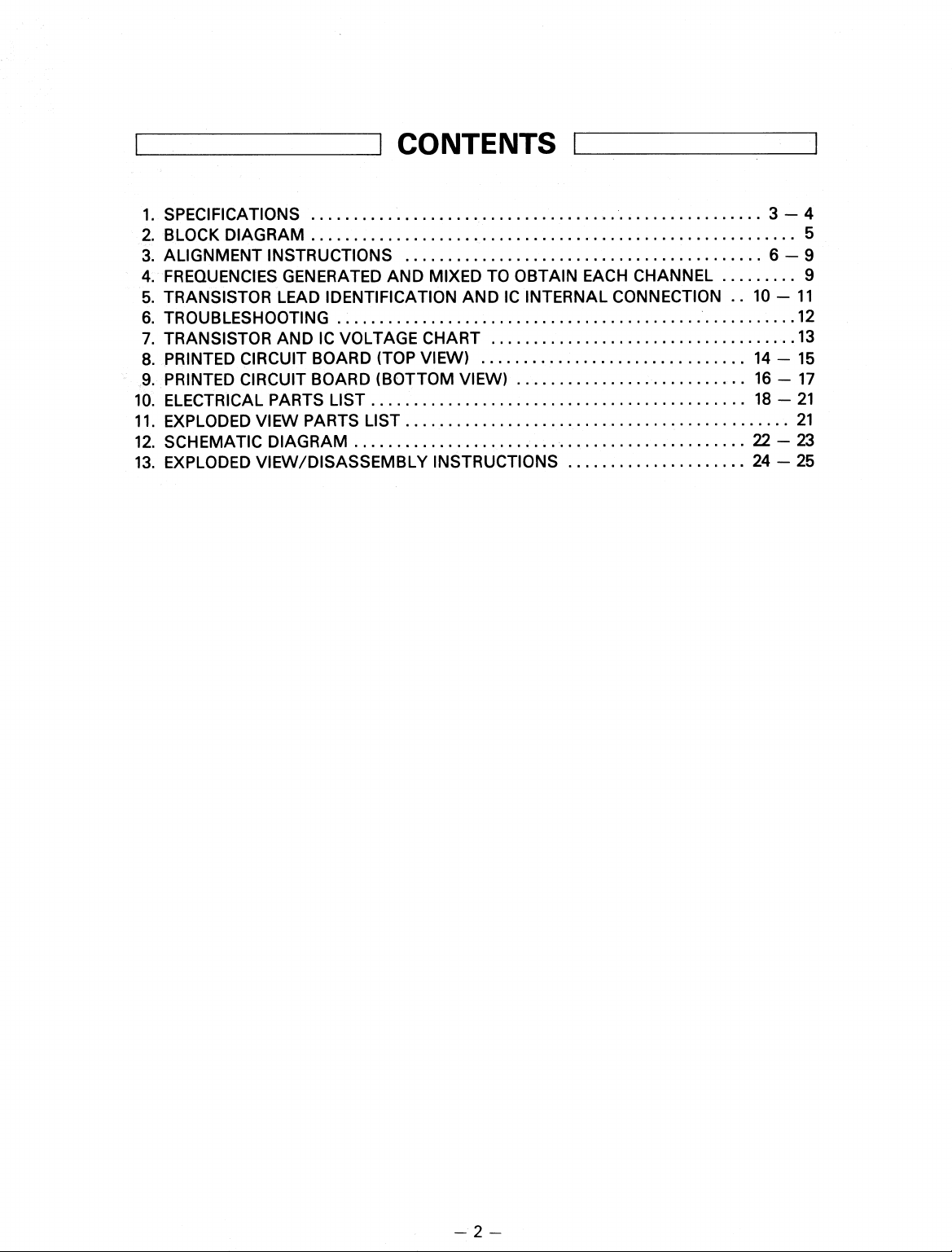
CONTENTS
SPECIFICATIONS
1.
BLOCK DIAGRAM
2.
ALIGNMENT INSTRUCTIONS
3.
FREQUENCIES GENERATED AND MIXED TO OBTAIN EACH CHANNEL
4.
TRANSISTOR LEAD IDENTIFICATION AND IC INTERNAL CONNECTION .. 10 - 11
5.
6.
TROUBLESHOOTING
7.
TRANSISTOR AND IC VOLTAGE CHART
PRINTED CIRCUIT BOARD (TOP VIEW)
8.
PRINTED CIRCUIT BOARD (BOTTOM VIEW)
9.
ELECTRICAL PARTS LIST
10.
EXPLODED VIEW PARTS LIST
11.
SCHEMATIC DIAGRAM
12.
EXPLODED VIEW/DISASSEMBLY INSTRUCTIONS
13.
3 - 4
5
6 - 9
9
12
13
14 - 15
16 - 17
18 - 21
21
22 - 23
24 - 25
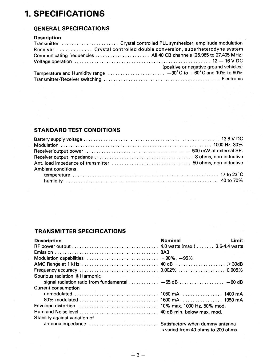
1. SPECIFICATIONS
GENERAL SPECIFICATIONS
Description
Transmitter
Receiver
Communicating frequencies
Voltage operation
Temperature and Humidity range
Transmitter/Receiver switching
STANDARD TEST CONDITIONS
Crystal controlled double conversion, superheterodyne system
Crystal controlled PLL synthesizer, amplitude modulation
All 40 CB channels (26.965 to 27.405 MHz)
(positive or negative ground vehicles)
C to + 60
°
—30
12 — 16 V DC
C and 10% to 90%
°
Electronic
Battery supply voltage
Modulation
Receiver "outputpower
Receiver output impedance
Ant. load impedance of transmitter
Ambient conditions
temperature
humidity
TRANSMITTER SPECIFICATIONS
Description
RF power output
Emission
Modulation capabilities
AMC Range at 1 kHz
Frequency accuracy
Spurious radiation & Harmonic
signal radiation ratio from fundamental
Current consumption
unmodulated
80% modulated
Envelope distortion
Hum and Noise level
Stability against variation of
antenna impedance
13.8 V DC
1000 Hz, 30%
500 mW at external SP.
8 ohms, non-inductive
50 ohms, non-inductive
17 to 23°C
40 to 70%
Nominal
. 4.0 watts (max.) . . . .... 3.6-4.4 watts
8A3
+90%, —95%
40 dB
0 002% . .... . . . . . ...
—65 dB
1050 mA
1600 mA
10% max. 1000 Hz, 50% mod.
40 dB min. below max. mod.
Satisfactory when dummy antenna
is varied from 40 ohms to 200 ohms.
Limit
> 30dB
0.005%
—60 dB
1400 mA
1950 mA
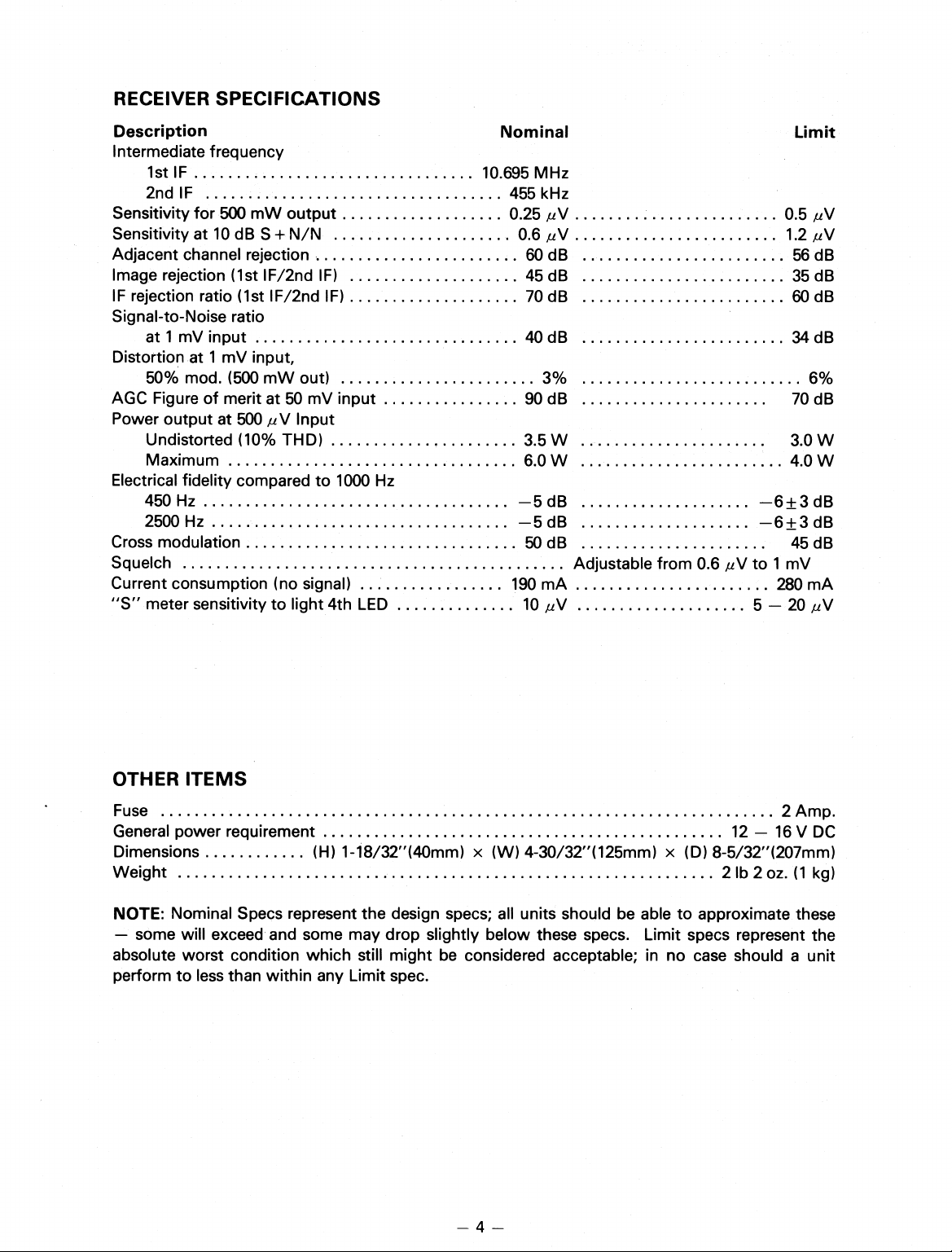
RECEIVER SPECIFICATIONS
Description
Intermediate frequency
1st IF
2nd IF
Sensitivity for 500 mW output
Sensitivity at 10 dB S + N/N
Adjacent channel rejection
Image rejection (1st IF/2nd IF)
IF rejection ratio (1st IF/2nd IF)
Signal-to-Noise ratio
at 1 mV input
Distortion at 1 mV input,
50% mod. (500 mW out)
AGC Figure of merit at 50 mV input
Power output at 500 ,uV Input
Undistorted (10% THD)
Maximum
Electrical fidelity compared to 1000 Hz
450 Hz
2500 Hz
Cross modulation
Squelch
Current consumption (no signal)
"S" meter sensitivity to light 4th LED
Nominal
10.695 MHz
455 kHz
0.25 ,uV
0.6 ,uV
60 dB
45 dB
70 dB
40 dB
90 dB
3.5 W
6.0 W
—5 dB
—5 dB
50 dB
190 mA
10 ,uV
3%
Adjustable from 0.6 AN to 1 mV
Limit
0.5 ,uV
1.2 AN
56 dB
35 dB
60 dB
34 dB
6%
70 dB
3.0 W
4.0 W
—6+3 dB
—6+3 dB
45 dB
280 mA
5 — 20 pV
OTHER ITEMS
Fuse
General power requirement
Dimensions
Weight
NOTE: Nominal Specs represent the design specs; all units should be able to approximate these
— some will exceed and some may drop slightly below these specs. Limit specs represent the
absolute worst condition which still might be considered acceptable; in no case should a unit
perform to less than within any Limit spec.
(H) 1-18/32"(40mm) x (W) 4-30/32"(125mm) x (D) 8-5/32"(207mm)
4
12 — 16 V DC
2 lb 2 oz. (1 kg)
2 Amp.
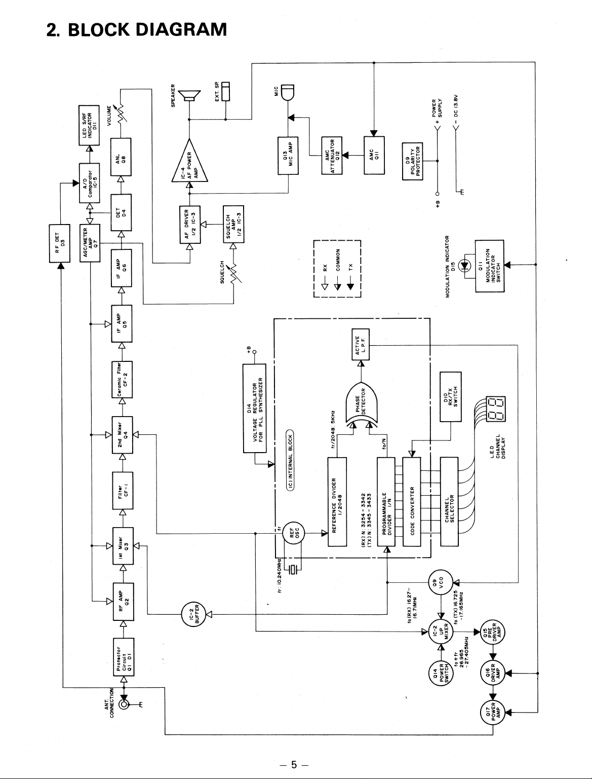
2. BLOCK DIAGRAM
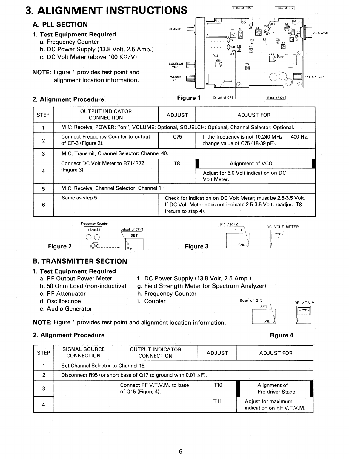
3. ALIGNMENT INSTRUCTIONS
Base of
Q15
Bose of 017
A. PLL SECTION
1. Test Equipment Required
Frequency Counter
a.
b.
DC Power Supply (13.8 Volt, 2.5 Amp.)
DC Volt Meter (above 100 KQ/V)
c.
NOTE: Figure 1 provides test point and
alignment location information.
2. Alignment Procedure
STEP
1
2
3
4
5
6
MIC: Receive, POWER: "on", VOLUME: Optional, SQUELCH: Optional, Channel Selector: Optional.
Connect Frequency Counter to output
of CF-3 (Figure 2).
MIC: Transmit, Channel Selector: Channel 40.
Connect DC Volt Meter to R71/R72
(Figure 3).
MIC: Receive, Channel Selector: Channel 1.
Same as step 5.
OUTPUT INDICATOR
CONNECTION
017
CHANNEL
SQUELCH
VR 2
VOLUME
VR I
Figure 1
ADJUST
C75
015 L5
TI I
=,3 fiR72
C75
Output of CF3
J
3R71
CF3
T8
©I
1-10
T5
ADJUST FOR
If the frequency is not 10.240 MHz ± 400 Hz,
5
L4
O
R2I
T4
T3
04
VR4
D VR5
oo
Base of 04 1
change value of C75 (18-39 pF).
T8
Alignment of VCO
Adjust for 6.0 Volt indication on DC
Volt Meter.
Check for indication on DC Volt Meter; must be 2.5-3.5 Volt.
If DC Volt Meter does not indicate 2.5-3.5 Volt, readjust T8
(return to step 4).
TI
T
al
ANT. JACK
EXT .SP. JACK
Frequency Counter
output of CF-3
Figure 2
B. TRANSMITTER SECTION
1. Test Equipment Required
RF Output Power Meter
a.
50 Ohm Load (non-inductive)
b.
c.
RF Attenuator
d.
Oscilloscope
e.
Audio Generator
NOTE: Figure 1 provides test point and alignment location information.
2. Alignment Procedure
STEP
1
2
3
4
SIGNAL SOURCE
CONNECTION
Set Channel Selector to Channel 18.
Disconnect R95 (or short base of Q17 to ground with 0.01 ,u F).
f.
DC Power Supply (13.8 Volt, 2.5 Amp.)
g.
Field Strength Meter (or Spectrum Analyzer)
h.
Frequency Counter
i.
Coupler
OUTPUT INDICATOR
CONNECTION
Connect RF V.T.V.M. to base
of Q15 (Figure 4).
Figure 3
ADJUST
T10
T11
R7I / R 72
DC VOLT METER
I
Base of QI5
Figure 4
ADJUST FOR
Alignment of
Pre-driver Stage
Adjust for maximum
indication on RF V.T.V.M.
RF V.T.V.M.
 Loading...