

Page 1
".
"
'"
OWNER'S MANUAL
PR
2005
Programmable Scanner_
Please
-,
read
before
using this
equipment
0"
Cat. No.
20-144
I"I<EALlshe
Page 2

INTRODUCTION
Your new Realistic® PRO-2005 Desk-Top Programmable
Scanner lets you
you direct access to over 196,000 frequencies
tion-packed radio bands including police,
aircraft,
to normal
ham
FM
select up to
through, and you can change your channel selection at
any ti
me
.
The
secret of your PRO-2005 scanner
designed microprocessor-a computer-on-a-chip-that allows you
to
to change any crystals. This microprocessor also gives
your scanner special functions, such
Liquid Crystal Display-shows the channel and the frequency you have selected,
Two-Second Scan Delay-helps to prevent your losing
replies
on
a channel while you are scanning.
Memory Backup-keeps the channel frequencies stored in
your scanner's memory if a power failure occurs.
Lock-Out Function-lets your scanner skip over a
specified channel or group of channels.
in
on all the action! Your scanner gives
in
nine ac-
fire,
ambulance,
radio, and transportation services,
broadcasts,
400
channels for your scanner to scan
TV
sound, and
in
CB.
You can
is
a custom-
addition
instantly select any frequency without having
as:
as
well
as
other information.
© 1988 Tandy Corporation.
Realistic and Radio Shack are registered trademarkes
All Rights Reserved.
Ten
Channel Storage Banks-allow you to group your
stored frequencies
so
that calls are easier to identify.
Priority ChanneJ-;helps to keep you from missing impor-
tant calls
on
the selected channel.
Direct Frequency Search-allows you to scan through
every available frequency to find interesting broadcasts.
Monitor Banks-allow you
to
save up to ten additional
channels located during a frequency search.
Sound Squelch- keeps the scanner from stopping on a
channel that
is
only broadcasting a carrier, with no voice or
other sound.
Your
PRO-2005
25
-520
•
•
760 -823.945
' .
851
•
896
-
-1300
scanner covers a wide frequency range:
MHz
MHz
868.945
MHz
MHz
of
Tandy Corporation.
2
Page 3
CAUTION:
TO
REDUCE
DO
NOT
NO
USER·SERVICEABLE
REFER
PERSONNEL.
It\.
The
lightning flash with arrowhead within the triangle
ill
is
intended to alert you to dangerous voltage inside
this unit that can cause shock. Do not open
enclosure.
THE
REMOVE
SERVICING
RISK
OF
COVER
TO
QUALIFIED
ELECTRIC
(OR
BACK).
PARTS
SHOCK,
IIIISIDE
SERVICE
WARNING: TO PREVENT FIRE OR SHOCK
HAZARD, DO NOT EXPOSE THIS
RECEIVER TO RAIN OR MOISTURE.
.
For your important records, please record your scanner's
serial number in the box below.
cated on the back panel of your scanner.
The
serial number
is
lo-
1.\
ill
The exclamation point within the triangle
to alert you
instructions
to
important operating and maintenance
in
this owner's manual.
is
intended
Serial Number:
______
_
3
Page 4

CONTENTS
A
Quick
Look
at
Your
Preparation ......
Battery
Power
Connecting
Using
Connecting
Connecting
Connecting
Understanding
A
A
Understanding
and
Operation
Programming
Searching
Moving a Frequency
Memory
Understanding
Frequency
Using
Setting
Using
Scanning
Using
Setting
Look
Look
Search
Sources
the
at .the
at
the
the
the
the
the
....
Installation.......................................................... 7
......... ..........
the
Antenna
Folding
Headphones
an
Extension
an
External
Your
Display
the
Keyboard ....
Channel
Banks
........................ ......
the
for
Active
to a Channel
Band
Steps
Restart
Volume
Sound
the
Channels......
Delay
Feature ........ ......
Scanning
Scanner
...
.......
....
...........
....
Feet
........
............................................ 10
Speaker.........
Tape
PRO-2005
............
Storage
...............
PRO-2005
Frequencies ....
from a Monitor
........................
Modes
............
Switch
Squelch
.... ....
......................
and
Squelch
Speed
Switch
.......................................... 5
.............
....
............ ............................ 8
........ ......
....
....
Recorder
Scanner
....
..........
................
Banks
..
........ ................
....
............. ......... ................ 17
Scanner ..
and
.................... ...
.............. ........
........
.....................
.......
..
..................... 9
......
....
.... .. .....
.............. 10
.....
................ 10
....
.............
.............
....
.......................
....
....
...... .............
..
..............
....
................
....
..................
....
............
.................................
.... ......
..........
.... ..
......................... .......
....................
.... ..
.. ...
..
...
...........
.... ..
.....
..........
....
.....
....
....... 18
.. ... 21
....
......
...
.....
..........
......
...
....
11
12
12
14
16
17
22
23
23
23
23
24
24
Locking
7
Turning
Using
Manually
Dimmer ....
A
General
Birdies
Cross
Reception
Guide
Typical
Maintenance .........
Before
Specifications
Out
Channels ............
Banks
On
and
Off
................
the
Priority
Selecting a Channel
Guide
.............
Modulation
Notes ... ...................... ...........
to
the
Band
You
Feature ............................................
....
........
....
.....................................................
to
....
Action
Usage
Call
for
...... ......
Scanning
.....................
..................
Bands
.. ................
......
....
Help
.. ..
......
........ .................... ...............
................
.........
.................
....
......
...
......................... 24'
......
...........
..........
....
..................................
...
....
............................
....
.................................
.......................................
..
...
..
....
....
......
....
...
............. .............
......
...
....
...
....
.............
........... .
...................
...............
... ...
......
...
......
...
....
25
25
25
25
26
26
26
26
27
28
30
31
32
4
Page 5
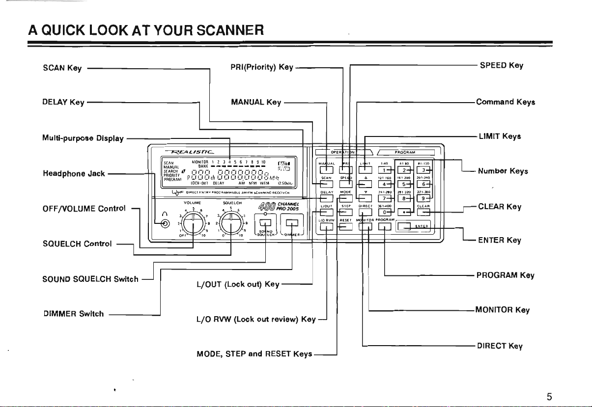
A QUICK LOOK AT YOUR SCANNER
SCAN Key
DELAYKey-----------~
Multi-purpose Display
Headphone Jack
--(F~~~~~~~======~~=;=k~$~~-;~~~~~~~~~~~~~---LlMIT
------\-,.,
OFF/VOLUME Control
SQUELCH Control
SOUND
SQUELCH Switch
DIMMER Switch
~£AL,snC-.
L/OUT (Lock out) Key
L/O
MODE,
PRI(Priority) Key
MANUALKey-----~
__
RVW
(Lock
out
review) Key
STEP
and
RESET
------,
....J
Keys
r-------------
,------------
Of'
ER T I N PRO
'---------
'-----------MONITOR
1.-
_________
GRA
SPEED
Key
Command Keys
M
Keys
Number Keys
CLEAR Key
ENTER
Key
PROGRAM Key
Key
DiRECT Key
5
Page 6

TAPE OUT
Jack
~ear
Panel
EXT.
SPKR Jack
13.8V Jack
81
®
\..81)
An
Switch
ANT (Antenna) Connector
6
F
~
~
l
~
@
81
TA T
RES
'-
R SWitch
~?)
~~
()
1-
@
AC Line Cord
-
@
Memory Backup Battery
Compartment
@
Page 7

PREPARATION
BATTERY INSTALLATION
Your scanner uses a 9-volt battery for memory backup. For
longest operation and best performance,
an
alkaline battery, such
For best results, replace the battery every six months.
"BATT"
battery
or install the battery immediately.
1
flashes
is
Remove the battery compartment
cover by loosening the screw
the back
in
low or not installed. When this happens, replace
panel.
as
Radio Shack's
the display and beeps sound when the
~~
on
we
recommend
Cat.
No.
23-553.
Remove the old battery, then snap 3
2
in
a new 9-volt battery. cover.
r~
Caution: Your scanner can keep channels stored
memory for a
plugged
loss of memory information, do not unplug the scanner
when replacing the battery.
In
scanner; even "leakproof" batteries
chemicals. Battery life
AC
period of time.
and
addition, never leave a weak or dead battery
power or automotive
few
minutes
the 9-volt battery disconnected. But, to avoid
is
Install the battery compartment
even
with the
can
about six months when household
DC
power
is
AC
leak damaging
off for a prolonged
cord
in
in
un-
your
its
~~
7
Page 8

_ POWER SOURCES
Car Battery Operation
You can power your scanner from the following sources:
AC
• A standard
• Your vehicle's battery (using
cable)
AC Power Operation
Connect the scanner's
outlet.
...
outlet
AC
power cord
an
optional
to
a standard
DC
power
AC
You can power your scanner from your vehicle's cigarette
12
lighter socket, provided the vehicle has a
ground system. To use
DC
power cable (Cat. No.270-1534B).
DC
Connect the
the rear panel. Then, plug the
cigarette lighter socket of your vehicle.
Note: Mobile use of scanners might
a permit
in
power cable's plug
some areas. Check with your local authorities.
DC
power, you need Radio Shack's
to
the 13.8 volt jack on
DC
power cable into the
be
volt, negative
unlawful or require
8
Page 9

CONNECTING
We
have provided a telescoping antenna with your scanner. This antenna
install
it
, simply screw
scanner.
THE
ANTENNA
is
adequate for strong local signals. To
it
into the hole on the top of the
@
om
~.
@ @
I!l
{U}
To install
1.
Select a location for the outdoor antenna that
as
2. Following the instructions that came with the antenna
and its mounting hardware, mount the antenna.
3. Connect the antenna to the scanner using coaxial cable.
Always use
feet, use
an
possible.
RG8
outdoor antenna:
50
ohm coaxial cable. For lengths over
low-loss, dielectric coaxial cable ..
is
as
high
50
•
Antenna length controls the sensitivity: adjust the length of
the telescoping antenna for best reception. Refer to the
table below.
25
MHz-300
300 MHz - 520 MHz
760
MHz-1300
Your scanner has better reception when you attach a
band outdoor antenna to
plete line of outdoor scanner antennas.
MHz
MHz
extend fully
extend 3 segments
collapse fully (one
ment only)
it.
Radio Shack stores
sell
seg
mUlti-
a com-
WARNING WARNING WARNING
When installing or removing outdoor anten-
If
nas, use extreme caution.
it
go!
It
starts to fall, let
head power lines.
could contact over-
IF
the antenna
THE ANTENNA
TOUCHES THE POWER LINE, CONTACT
WITH THE ANTENNA, MAST, CABLE,
OR
GUY WIRES CAN CAUSE ELECTROCUTION
AND DEATH! Call the power company to
Do
remove the antenna.
not attempt to do
so yourself.
9
Page 10

USING THE FOLDING FEET
Your scanner's front feet are folding type.
cording to the location of the scanner.
CONNECTING HEADPHONES
For private listening or
phones into the headphone jack
in
Plugging
ternal speaker.
set
(Cat.
f.
headphones automatically disconnects the
We
No.
20-210).
~'
in
a noisy environment, plug head-
on
front of your scanner.
recommend Radio Shack's mono head-
~
~
CONNECTING AN EXTENSION SPEAKER
In
a noisy
Shack's
might provide more comfortable listening. Plug the speaker
cable's 1/8-inch mini-plug into your scanner's
jack.
Cat.
area,
No.
an
extension speaker (such
21-549), positioned
Use
them ac-
~
t
t
~
'
,
;;/
l.
~~~
~t
"
as
in
the right place,
EXT
in-
Radio
SPKR
10
Page 11

CONNECTING AN EXTERNAL TAPE
RECORDER
You can record scanner transmissions with a tape recorder
through the
Shack store for the appropriate connecting cable.
TAPE
OUT jack. Consult your local Radio
e
@@
~
0[1
~
11
II
~~
·
~"======O\\F
.
~
11
Page 12

UNDERSTANDING YOUR PRO-2005 SCANNER
A LOOK
The display
your scanner's current operating mode. A quick look at the
display will help you understand how your scanner
operates.
The
above illustration shows your scanner's display with
the indicators
indicators.
BANKmemory banks are currently turned
See
Banks.
SCAN - comes
DELAY - appears when the scanner
you
the Delay Feature."
AT
THE DISPLAY
SCAN
MANUAL
SEARCH"
~~~~R~l~
has
several abbreviated indicators that show
on.
The
following
bars to the right of this indicator show which
"Understanding Channel Storage Banks and Search
"
on
when the scanner
have
programmed with the delay feature.
is
MONITOR
BANK
I-' I-'
p
c,
C, C,
LOCK-OUT
a brief explanation of the
on
for the scan mode.
is
in
the scan mode.
is
on a channel that
1 2 3 4 5 6 7 8 9
- - - - - - - - - -
,-,
I-'
I-'
ch
C,
C, C,
DELAY
all
See
"Using
10
I-'
I-'
I-'
,-,
I-'
C'.
C,
C,
Cr
H
AM
NFM
WFM
LOCK-OUT
to
is
locked out of the scan mode.
nels."
MANUAL-comes
channel selection mode.
ch - digits preceding this indicator show which channel the
scanner
MHZ-digits
the scanner
MONITOR-appears when the scanner
mode.
to a Channel."
PRIORITY
channel feature.
-appears
is
currently tuned to.
preceding this indicator show the frequency
is
See
"Moving a Frequency from a Monitor Memory
-appears
II1.jj)
[illill]:i]
- ' , I '
MHz
12.50kHz
when the channel you are listening
on
when the scanner
currently tuned
when you
to.
See
have
"Locking Out Chan-
is
in
the manual
is
in
the monitor
turned
on
the priority
12
Page 13

PROGRAM-appears when the scanner
programming.
BATT
-flashes
when the batteries need to
replaced.
is
ready for
be
installed or
P - appears when you
SEARCH
quency search
-appears
....
are
during a limit search or a direct fre-
and
...
also appear
the direction of the search.
AM, NFM,
selected.
WFM-shows
See
"Understanding
Steps."
5,
12.5,
50
- shows which frequency step
selected.
See
"Understanding
Steps."
listening to the priority channel.
in
the display to show
which band mode
Band
Modes and Frequency
Band
Modes and Frequency
is
currently
is
currently
13
Page 14

A LOOK AT
THE
KEYBOARD
OP
ERATI
ON
\ /
MANUAL
PRI
LIMIT 140
DDDWww
SCAN SPEE D b.
DDD0CTIo]
DELAY MODE V 241·
DDDCTI[Dw
1I0UT STEP DIRECT 361 ·
DDDCTI8D
La
D
MO"
P
PROGRAM
41·80
121-160
161·
200
2aO
281·
320
400
EflD
81·
120
201·
240
321·360
CLEAR
ENTER I
The
keys on your scanner might
seem
cryptic at first, but a
quick glance at this page should help you understand each
key's function.
Number
numbers printed above
Keys-each
has a Single
it.
The
single digit is the number
digit, and a range of
entered when you are entering a channel number or a fre-
(1-40,
quency. The range of numbers
the channels that make up a memory bank.
for example) shows
See
"Under-
standing Channel Storage Banks and search Banks."
SCAN - causes your scanner to scan through the
programmed channels.
MANUAL-
stops scanning and allows you
to
directly enter
a channel number.
14
CLEAR-deletes
LlOUT - turns on the lockout function.
an incorrect entry.
See
"Locking Out
Channels."
RVW
LlO
DELAY
- recalls locked out channels sequentially.
-turns
the delay feature
on
or off for the current
channel.
SPEED
MONITOR -
-changes
is
used to access the monitor memories.
the scanning and search speed.
See
"Moving a Frequency from Monitor Memory to a ChanneL"
PRI-
selects the priority channel.
Page 15

PROGRAM -
channels.
is
used
when programming frequencies into
ENTER - used
to
enter the frequency when programming
channels.
LIMIT,
See
DIRECT - starts the direct search.
MODE-changes
A,
and
...
-are
used during frequency searching.
"Searching for Active Frequencies."
the band mode
in
the following order:
AM-NFM-WFM .
STEP - used to change frequency steps
order: 5 kHz-12.5 kHz-50
RESET - initializes band mode and frequency step.
kHz.
in
the following
15
Page 16

UNDERSTANDING CHANNEL STORAGE
BANKS AND SEARCH BANKS
Your scanner can store up to
in
each frequency
channel, or a temporary memory, called a monitor. The
has
it
easier
400
scanner
To
make
want to listen to, channels are divided into ten groups of
channels. Each group of channels
haps the best way
through a practical example.
Suppose you want to monitor four different agencies:
police, fire, ambulance, and aircraft.
has
several different frequencies they
poses. The police might have four frequencies, one for
each side of town. To make
which agency you are listening to, you could progmm the
police frequencies starting with Channel 1 (Bank
start the fire department on Channel
bulance service on Channel
quencies on Channel
either a permanent memory, called a
channels and ten monitor memories.
to
identify and select the channels you
to
explain the use of memory banks
121
410
frequencies. You store
is
called a bank. Per-
As a rule,
use
it
easier to quickly determine
81
(Bank
(Bank
4).
each agency
for different pur-
41
(Bank
3),
and aircraft fre-
1).
2),
40
is
Then,
am-
corresponding to the bank you want to turn on or
in
bar below the number
Your scanner also has ten temporary monitor memories.
use
You
while you decide whether to save them
manent channels. This
tive frequency when you are searching through
band.
When you are
top of the display represent the ten monitor memories. The
flashing number shows the current monitor memory.
In
use
See
these memories to store frequencies temporarily,
See
"Searching for Active Frequencies."
in
the monitor mode, the ten numbers at the
addition, your scanner
these banks to store your selected limit search ranges.
"Searching for Active Frequencies."
the display shows that bank
in
one of the per-
is
handy for quickly storing
has
ten search banks.
off.
an
You
The
is
on.
an
ac-
entire
can
Now, when you want to listen to only fire calls,
10
to turn off Banks 1 and 3 through
scanned. You could also use this feature to group the
channels by city or by county. Simply press the number
so that only Bank 2 is
it
is
simple
16
Page 17

OPERATION
PROGRAMMING THE PRO-2005 SCANNER
Select a channel to program by pressing [MANUAL], and entering the
1
channel number you want to program. Then, press [PROGRAM]. "PROGRAM" appears
gramming mode.
in
the display to indicate that your scanner
is
in
the pro-
c
:j'
DO
o D
o D
ooo
D
0(G]
[IJ
CD)
O:IZJ
[TI
OJ!
OICIJ
m-QJJ
ol~JGJO
"
D~~
Enter a frequency.
2
A good reference for active frequencies
tory Including Fire and Emergency Services.
yearly, so
be
sure to get a current one. Also refer to "Reception Notes" and
"Searching for Active Frequencies"
Press [ENTER].
3
This stores the frequency. If you made a mistake
pears
in
the display and three beeps sound. Press [CLEAR] and proceed
is
Radio Shack Police Call Direc-
in
this manual.
We
update this directory
in
Step 2,
"ERROR"
again from Step 2.
Press [DELAY] .
4
If you want your scanner to pause after each transmission before scanning
to the next channel, press [DELAY]. "DELAY" appears
do
not want your scanner to pause, press [DELAY] again. "DELAY" disap-
in
the display. If you
pears from the display.
Repeat Steps
5
Note: If you want to program the next channel
1-4
to
program more channels.
in
sequence, just press
[PROGRAM] and proceed to Step 2.
ap-
o 0
o(m
o D
OIIZJ
o D
O:CIJ
o D
Ol~U~JO
0000
ODDCIJmm
oo
o
mGJD
0000
ooomITJCIJ
OOOIZJ[TIm
DDoCIJmm
000ITJ80
oooo~
00D0mm
OODITJGJO
ooo'"D
[IJ
[TI
[TIm
Q:=J
[0
'·"'
~
cril
OJI
[
17
Page 18

SEARCHING FOR ACTIVE FREQUENCIES
Use these procedures
Also, see "Guide
to
search for a transmission. This
to
the Action Bands"
in
this manual.
is
Limit Search
The limit search procedure allows you
in
the search banks.
Press [PROGRAM], and the search bank number
1
wish
to
store the limit search range. Press 0 for bank number
10.
Press [LIMIT]. "L" and the search bank number appears in the
2
display.
Enter the lower limit of the frequency range. Then, press
3
[ENTER].
Press [LIMIT]. "
4
Enter the upper limit of the frequency range. Then, press [EN-
5
L"
changes
to
TER].
to
search within a range of frequencies. You can store up
"H" in the display.
in
helpful if you
which you
do
not have a reference to frequencies in your area.
to
ten limit search ranges
I
PROGR
AM
L
I
PfU)GM
M
L
I
PROGRAM
L
I
P
ROGR
AM
L
I I
PROGRAM
L
1 2 3 4 5 6 1 8 !I
BANK
-
,n
'U
th
,
J
'-
'-
,
-,
L C
:'
,-,
"
L
J
,-,
L
"
:'c
'-
'e
,
_'U.UUU
,
:'
,-, ,-,
,_'U
,-, :''-''-''-',-,
, ' _'.U U U 'J
10
-,
C
M-Iz
'-"-''-',
AM
,-, ,-,
NFM
.IM
NfM
,-,
-,
,_,
M-Iz
uM-lz
,-
,
M-Iz
J .U U U
'-"-''-''-',-,
U.U U U 'JM-Iz
5
12.S'H
s
,,~
I
..J
I
..J
I
'H~
I
~
18
Page 19

Repeat steps 1-5 to
6
search banks. You can store
To
7
recall a limit-search range, press the appropriate bank num-
ber.
Press
[y]
to
8
limit. Or press
search from the upper limit
[.]
limit.
store the limit-search
up
to
10
limit-search ranges.
range into
down
the
to the lower
to search upward starting from the lower
I
PROGRAM
L
I
MANUAL
L
I
SEARCH
L
,
-,
:1
L
12345618910
BANK
-
,,-,
I Lf
cn
MONlTOR:j:2 J 45618910
....
J
L
,e
1
:Ie
L
_I
'-''-''-',-,
_I
Lf Lf Lf
AM
'-',-,,-,e
LfIJ
Lf
NFM
:'
L
_1,_,
I
L'
M-fz
--.J
I
M1z
--.J
I
,-,
Mil
5
kH~
When the scanner stops on a transmission, press [MONITOR]
9
to
store the frequency in the current monitor memory. The
memory number flashing on the display indicates the current
monitor memory.
To continue the search, press
10
[Y]
or
[.]
.
Notes:
• Press [SPEED]
• Press [DELAY]
to
speed up
to
make the scanner pause 2 seconds after a transmission, before proceeding
or
slow down the search.
I
SI:ARrn
L
I
SEARCH
L
...
&
MONITOR',j
,,-,
1 Lf
MONITOR
L
: 2 3 4 5 6 1 8
,,-
1:1
cn
1
:*',3 4 5 6 7 8 9
, e
:1
_I
I
910
1'-'
-"-,,-,
I.Lf I Lf '-'
NFM
10
,,,
-II:
I.LI 1 J
NFM
to
the next frequency.
"
,_,
11Hz
Mil
5
5
I
kH~
I
kH~
19
Page 20

Limit-Search Memory
When you change your scanner's mode from limit search to manual, program, scan, direct search, and so on, your scanner
retains the last frequency before you change the mode. Your scanner resumes the search from that frequency when you
change the mode to limit search again.
Note: You can change the upper
or
lower limit frequency without affecting the memorized frequency if the frequency is
within the new limit range. If the frequency is out of the new limit range, the search starts from the new upper
frequency.
Direct Search
When you are
Select
1
[MANUAL],
[MANUALj
Press [DIRECTj. The step frequency appears
2
Press [A 1 to search through higher frequencies
3
search through lower frequencies.
When the search stops on a transmission, you can store that
4
frequency into a monitor memory by pressing [MONITORj. The
memory number flashing on the display indicates the curreht
memory number. To continue the search, press
20
in
program or manual mode, you can search up or down from the current frequency.
currently programmed
a
the
and
or
[PROGRAMj.
channel
channel
by
pressing
number. Then, press either
in
the display.
or
[~J
to
[~j
or
[A
j.
I
MANUAL
L
I
MANUAL
L
I
SEARCll
L
I
SlARCH
L
BANK
['5E1ch
BANK
-,,-,-,
C
':IO
M
ONITOR 1:?:
A
- - -
MONITOR
..
['5E1ch
12
J 4 5 6 7 8 9
',_'ue
I I 1.
_IUW'-'
NIM
1 2 J 4 5 6 7 8 9
',_'u'-"-"-'
, ,
ch
1;~
/.UUW,-,
NI
J 4
56789
:
'-:
'-:e:
NFM
:
3 4 5 6 7 8 9
"_'0
-,
, I_I. , 'U,-,M-Iz
NfM
10
'-"-',-,
MHz
10
,-,
M-Iz
M
10
e:
5
MHz
10
''-',-,
or
lower limit
I
-.J
I
5
'".:.J
I
5 '
".:.J
I
H~
Page 21

Notes:
• When you press [DIRECT] during limit, your scanner enters direct search mode.
• When you press a numeric key during a direct search, your scanner changes to limit search mode. The key you
press corresponds with the limit-search bank number.
MOVING A FREQUENCY FROM A MONITOR MEMORY TO A CHANNEL
As
you store frequencies
memory. You can listen to monitor memories by pressing [MANUAL], [MONITOR], then the number of the monitor memory
you want to listen to.
in
monitor memories, the memory number flashing on the display shows the current monitor
If there
is
a frequency you wish
Press (MANUAL], and the channel number
1
to
transfer to a channel, follow this procedure to move
in
which you want
to store the frequency. Then, press [PROGRAM].
Press (MONITOR], and the memory number you want to
2
move.
Press [ENTER]. The scanner stores the frequency
3
nel
you entered.
If you want to return
to
a limit search after this procedure,
in
the chan-
press (LIMIT], and the search bank number. Then, press
either (
...
] or
it
from the monitor memory:
I
PROGRAM
L
I
PROGRAM
L
I
PROGRAM
L
['f']
to continue searching.
12345618910
8ANK
'e'-'
,-,.-..-..-..-.,-,.-.,-,
'_'LI
en
UUUU.UUUulMl
MONITOR
1 :?: 3 4 5 6 7 8 9
12345678910
BAN
K
,,-
,-,
,:, Ueh , , _', I ILl u
(1)0-'
I I_I, ,
(1)0-'
''-',-,
'UuM-lz
NFM
''-',-,
NfM
I
~
10
I
~
I
M1z
~
21
Page 22

UNDERSTANDING BAND MODES AND
FREQUENCY STEPS
We
designed your scanner to adjust itself for the band
modes and frequency steps for each frequency range.
Default settings are as shown below.
VS.
FREQUENCY
FREQUENCY (MHz) MODE
25.000 - 29.995
30.000 - 87.495 NFM
87.500 - 107.995
108.000 - 135.995
136.000 - 224.995
225.000 - 520.000
760.000 - 1300.000
WFM: Wideband
sound.
MODE AND
FM
for normal
STEP
AM
WFM
AM
NFM
NFM
NFM
5
5
50
5
FM
broadcasts or
STEP
12.5
12.5
12.5
(kHz)
TV
Normally, the preset mode/step works within each band as
shown above. However, for some of the ham radio, military
aircraft (225-400 MHz), and
must change the mode or step manually. To change the
band mode, press [MODE] when your scanner is
manual mode. To change the frequency step, press
[STEP] in search mode. Note that when you change the
preset modes/steps, the corresponding indicator flashes to
show you that you changed the default setting.
When you want
[RESET]. The display stops flashing.
Keep
in
mind that improperly setting the modes or steps
can cause poor reception. When you listen
broadcast or
distorted. If you monitor police band
sound
steps to search for
might stop on the sideband of the frequency.
press
kHz steps for
between the
is
masked by noise. Or
[.]
or
to
return to the default setting, press
TV
sound
FM
['Y
I to get the center frequency. If you use
NFM
band, you might miss the frequencies
50
kHz steps.
TV
audio
in
the
NFM
mode, the sound
if
you use 5 kHz or 12.5 kHz
broadcasts or
(WFM)
in
TV
bands, you
to
WFM
mode, the
sound, the search
In
that case,
an
is
in
FM
very
50
NFM: Narrowband
ambulance, ham radio, and so on.
AM:
For aircraft band, C8, and so on.
22
FM
for action radio bands, police, fire,
Page 23

USING THE RESTART SWITCH
The scanner's display might lock up the first time you plug
in
and
turn on your scanner, or if the battery
an
extended period of time. If the display locks,
pO
inted object, like a paper clip, to press and release the
restart switch while power
To clear
and:
1.
2.
3.
all
the memories,
Press and hold [CLEAR].
Us!ng
a pointed object, press and release the restart
SWitch.
After confirming that the display goes blank
[CLEAR]. '
is
on.
be
sure the scanner
is
left out for
use
is
turned
release
on
SETTING THE VOLUME AND SQUELCH
Turn
VOLUME
until you hear a hissing sound.
SQUELCH
set
to a comfortable listening level.
If the scanner picks
SQUELCH
to these signals.
clockwise and SQUELCH counterclockwise
Then,
clockwise until the noise stops. Leave
up
unwanted weak transmissions, turn
clockwise
to
decrease the scanner's sensitivity
slowly turn
VOLUME
USING THE SOUND SQUELCH SWITCH
If
the scanner stops at a transmission during
or priority modes, the [SOUND SQUELCH] switch lets the
scan,
search,
if
scanner start scanning again
no sound (carrier only without modulated signals).
If your scanner stops at a frequency that
press [SOUND SQUELCH].
a
scanner detects no sound within 0.5 seconds, it goes to
the next transmission.
When the scanner receives a frequency that contains
sound,
scanner stays
resumes scanning.
to scan immediately
seconds
To
again. The indicator goes off. .
Note:
modulation, the sound squelch circuit might not work
properly.
it
halts at the frequency.
on
the frequency for 5 seconds, and
If
the carrier stops, the scanner begins
if
the delay function is off, or after 2
if
the delay function
cancel sound squelch, press [SOUND SQUELCH]
If
a frequency contains a transmission with low
the transmission contains
has
The
indicator lights. If the
If
the sound ceases, the
is
on.
SCANNING THE CHANNELS
To begin scanning channels, just press [SCAN]. Your
all
scanner scans through
locked out of the banks that are turned
SQUELCH
tween transmissions.
to get the full benefit from the special features of your
scanner.
so that you do not hear the hissing sound
the channels that you have not
on.
You must set
Be
sure
to
read
the following sections
no sound,
be-
23
Page 24

USING THE DELAY FEATURE
SETTING THE SCANNING SPEED
Many agencies use two-way radio systems that might have
a period of several seconds between a query and a reply.
To
keep from missing a reply, program a delay on the
channels you identify
delay, manually select the channel, and press [DELAY].
"DELAY" appears
ning through channels, your scanner pauses for two
seconds after the completion of each transmission on that
channel before resuming scanning.
Some radio systems, especially those above
a special "trunked" system.
ter selects an available frequency each time the operator
keys the radio. Therefore,
on one frequency and the reply on another. To ensure the
best possibility of hearing the full reply, you want the scanner to begin scanning immediately when the first transmission ends.
ensure that "DELAY"
cated, press [DELAY] to turn off this feature for that channel.
In
this case, select the channel manually and
as
operating this way. To program a
in
the display. Now, when you are scan-
800
MHz,
In
these systems, the transmit-
it
is possible for the query to be
is
not
in
the display. If "DELAY"
is
use
indi-
Your scanner has two different scanning speeds - 8 channels per second and 16 channels per second. To switch
between the two scanning speeds, press [SPEED] during
scanning.
LOCKING OUT CHANNELS
You can increase the effective scanning speed by locking
out channels that you have not programmed. Manually
select the channel, and then press [LlOUT], so that "LOCK-
OUT"
appears
out channels that have a continuous transmission, such
a weather channel. You can still manually select locked-out
channels for listening.
To disable the lock-out function, manually select the channel
and press [LJOUT].
program mode to call out locked-out channels one by one.
Then,
press [LIOUT] again.
Note: You can lock out
there must
ed
out
in
in
the display. This
Or,
as
many channels
be
at least one channel that you have not lock-
each bank.
is
also handy for locking
press [LIO
RVW]
as
as
in
manual or
you like. But
24
Page 25

TURNING BANKS ON AND OFF
As
explained
and Search Banks" your scanner splits the
into ten banks of forty channels each. The small bars under
the numbers at the top of the display
dicators. You can turn each bank on and
channels
scan mode, press the number key for the bank you want to
turn on or off. If the bank indicator
on the bank and the scanner scans
that bank that you have not locked out. If the indicator
off, the scanner does not scan any of the channels within
that bank. You can' still manually select any channel
bank, even if you have turned off the bank. You cannot turn
all
banks - one must
off
in
"Understanding Channel Storage Banks
400
are
the bank in-
off,
so that
in
a bank are either scanned or locked out.
is
on,
you have turned
all
the channels within
be
turned
on.
channels
all
the
In
is
in
USING THE PRIORITY FEATURE
You can scan through
still not miss
channel. Simply program your desired channel as the
priority channel, and turn on the priority feature by press-
[PRI] during scanning.
ing
priority channel every two seconds, and stays on the channel
if
there is activity.
an
all
your programmed channels, and
important or interesting
The
scanner now checks the
call
on a specific
To program a priority channel, simply press [PROGRAM),
Then,
press
and the desired channel number.
in
pears
priority channel.
priority channel. If you program a new channel
priority channel, the previous channel you chose
automatically cleared.
Note: Channel 1
channel the first time you turn
the display whenever the scanner
You
can
only program one channel
is
automatically designated as the priority
on
your scanner.
[PRI). "P"
is
MANUALLY SELECTING A CHANNEL
You can continuously monitor a single channel without
a
scanning. This
cast on a channel and
details - even though there might
if
you want to monitor a channel that you have locked out.
To select a channel to monitor, just press [MANUAL), and
enter the channel number .
Or,
if your scanner
desired channel, just press [MANUAL] once. Pressing
[MANUAL] additional times causes your scanner to step
through the channels one at a time.
is
useful
if
is
scanning and
you hear
do
not want
Then,
an
emergency broad-
to
miss any of the
be
periods of silence - or
press [MANUAL] again.
has
stopped
DIMMER
Press [DIMMER] to turn the display's backlight down or
up.
set
to
as
as
at
ap-
the
the
the
is
the
25
Page 26

A GENERAL GUIDE TO SCANNING
BIRDIES
Birdies are the products
make some frequencies difficult or impossible to receive. If
you program one of these frequencies, you hear only noise
on that frequency.
If the interference
SQUELCH clockwise
mon birdies
to
watch out for are listed below.
Birdie Frequencies
44.360MHz
48.045
59.500
70.235 249.750
70.085 250.500
73.930
76.770 279.1875
79.435
79.800 298.8125
80.520 309.800
83.170 310.600
84.260 327.500
85.020 342.000
86.865 342.800
122.375
122.875
130.9375 464.250
144.135 465.250
155.125 488.375
203.500 501.4375
208.oo0MHz
220.750
244.250
278.4375 818.000
298.0625
366.000
366.750
of
internally generated signals that
is
not severe, you might be able to turn
to
cut out the birdie. The most com-
767.4OOMHz
769.800
803.550
805.950
815.600
819.750
822.250
851.875
854.375
856.875
867.9375
900.0625
902.5625
905.0625
916.125
918.625
921
.125
948.250
950.750
953.250MHz 1232.600MHz
1015.000
1017.500 1243.050
1026.000
1052.750
1088.875 1258.500
1098.250 1260.000
1104.250 1262.750
1107.000
1109.750
1112.500
1163.6875 1277.950
1166.4375
1169.1875 1288.400
1203.3125
1206.0625 1294.400
1208.8125
1224.200
1227.000
1229.800
1240.250
1245.850
1248.650
1265.500
1272.350
1275.150
1280.750
1291
1296.800
.200
CROSS MODULATION
When using
to
the reception frequency might cause cross modulation
(like cross talk). Set the
dB to minimize cross modulation.
an
external antenna, a strong frequency close
An
switch on the back panel to
-10
RECEPTION NOTES
Reception on the frequencies covered by your scanner
mainly "line of sight." That means you usually cannot hear
stations
at
your listening location that are located beyond
the horizon.
During summer months, you might
in
the
30-50
MHz range located several hundred or
thousands of miles away. This
spheric conditions. This type or reception
be
able to hear stations
is
due to summer atmo-
is
unpredictable,
but often very interesting!
One very useful service
is
the National Weather Service's
continuous weather broadcasts. These broadcasts contain
weather forecasts and data for the area around the station,
plus bulletins on any threatening weather conditions.
These stations use three frequencies:
162.40, 162.475, and
162.55 MHz. In most areas of the country, you can receive
one of these frequencies.
is
even
26
Page 27

GUIDE TO THE ACTION BANDS
With the right frequencies programmed into your scanner,
you can monitor exciting events. With a little investigation,
can
you
give you some general pointers, and you can take
there. Please
hear an emergency call. Never go to the scene of
gency ever
Find out if there is a local club that monitors your
community's frequencies. Perhaps, a local electronics
repair shop that works on equipment similar to your scanner can give you channel frequencies
services. A volunteer police or fire employee can also be a
good source of this information.
As
tween
find active frequencies
use
caution and common sense when you
it
could be the most dangerous thing you could
do
.
a general rule on
VHF,
153.785 and 155.98 MHz and then again from
153.73 to 159.46 MHz. Here you find local government,
police, fire, and most such emergency services. If you are
near a railroad yard or major railroad tracks, look around
160.0 to 161.9 for signals.
In
some larger cities there
bands for emergency services. Here, most of the activity
in
a spread of 453.025-453.95 MHz and again between
456.025-459.95 MHz.
in
your community.
used
most activity concentrates be-
has
been a move to the UHF
We
can
it
from
an
emer-
by local radio
is
In
the UHF band, mobile units and control units associated
in
with base and repeater units occur
456.025-459.95
operate
464.975
find an active frequency inside one of these spreads, you
can
find that radio service.
A new
the
agencies use trunked radio, introduced to business systems
the transmitter automatically selects
each time it
a system without causing interference. This system
also
for selected units, with unselected units unable to hear the
message.
Frequencies
specific intervals. However, the frequencies that you can
store into your scanner's memory are
or
entered frequency down to the nearest valid frequency. For
example, if you try to enter a frequency of
scanner accepts this entry as
5 MHz lower (that
MHz) than the base units. This means that if you
look 5 MHz lower (or higher, as the case may
technology
800 MHz band for many services. Some public safety
in
1979. With as many
be
programmed to provide secure communications
50
kHz steps. Your scanner automatically rounds the
and
465.025-469.975.
is,
451.025-454.95 and 460.025-
is
now available that allows the
as
is
activated. Several agencies
in
different bands are accessible only at
151.470.
the overall spreads of
The
repeater units
be)
to
use
of
twenty channels available,
an
unused channel
can
share such
can
in 5 kHz,
12.5
kHz,
151.473, your
27
Page 28

TYPICAL BAND USAGE
The following is a brief listing of the typical selVices using
the bands your PRO-2005 can receive. This listing can help
you decide which ranges you would like to scan.
PO
....
....
...
Abbreviations:
BA
........................
CA
.... ..
................................
CAP
........
IB
.... ..
...
........................
IF .....................
1M
..................
IP ................................
IS
...... Special Industrial (Construction ,farming ,etc.)
IT..
...........................
roN
...............................
IX .................................................... Manufacturers
IV
...............
LA
.................. Automotive Emergency
W ..................
LA
.............................
LU
..................
LX
....
.....................................
MC
....
.... ..
MG
.; .............. Maritime Government
MP
........ Maritime Public Coast (marine telephone)
MS
....
..................................
PF
............................
PH
...................
P
~
................
/
PM
.............................................. Medical
Remote
Broadcast
.......
..................................
..............................
....
....
......
Relay
......
....
...
...
Maritime Umited Coast (private stations)
.... ..
...
.........................
General
........
...
............. Motion Picture Industry
......
....... Petroleum Industry
......... Telephone Maintenance
....
Power
Press
(newspaper reporters)
.........
....
. Motor Carrier, Trucks
....
..........................
................
..............
..
....
...
................. .
Highway Maintenance
(Radio
Mobile
....
............ Business
Forest
and
Motor Carrier,
......
..................
(Coast
Maritime Shipboard
...................
Local
&
(Radio)
Civil
Air
Patrol
Products
Water Utilities
(tow
trucks)
..
Railroad
Buses
..
Guard)
Government
Services
PP
TV)
PS ..........
RA.
RC ......
RT..
BIFC
Government Agencies:
UAF ..........................
UAR
UBW
......
UCE
UCF
UCG ....
UCM
UCO .
Taxi
UCP
UCW
UCX
UEP
UER
Fire
UFA ................
UFC
UGC ....
UGF
..............
..............................................................
........
...........................
.......... Mobile Telephone
....
.......................
............. Environmental
...
.................................
.....
....
.............
............
...............................
..........
............
................
..
Mobile Telephone (radio common
.... ..
..................
..........
....
............
.........................
..
.........
....
............... International Boundary &
....
.........
....
....
............................. Coast
.........
.. ............
....
.............
.........
.........
...
...
............... National Weather
....
..........
....... Environmental Protection Agency
.....
..
..
Federal
.................
....
................
some from area to area. For a more complete listing. refer
to the "Police Call Radio Guide Including Fire
cy
Services." at your local Radio Shack .
....
.......... Forestry Conservation
...
....
...
....
Boise
...............................
...
..........
........
........... National Capitol Police
...
Federal
Communications Commision
Special Emergency
Mobi
le
Telephone (aircraft)
Oandline
Interagency
......
........
..................
....
Water Commi
Research
..
Maritime Fisheries
Mar
itime Administration
..............
Qepartment of Commerce
...
..
Department of Energy
Aviation Administration
Soil
Conservation
.........
........
..
Police
carrier)
companies)
Fire
Cache
Air
Force
. Pimy
ssion
Laboratories
Service
Guard
Ocean
Survey
Service
Service
Forest
Service
UGS
UGX .............................. Department of Agriculture
UHW ....
UIB
...................... Bonneville
UIF
.............. Bureau
UIG
.................. .. ..
UII .....
UIL ....
UIM
............
UIP
...............
UIR .................................
UIS
................. Southwestern
UIX ........................
UNO
UNS ...
UPO
USA .....
USD
.........................
USN
UTC
......................................
UTM
UTR ......................... Department of Transportation
UTV ...
UTX
...................................... Treasury Department
lNA ..................................
UXX
......................
These frequencies are subject
to
change. and might vary
................
...
...............................
.............................................
......................................... ..
..........................................
....
...
..
General
Services
......... Dept. of Health and Human
........ ....................
....
...................
......................
...
......................
............
....
..........................
......
.................. National
......
...
.... .......................
..........
Power
of Sport Fisheries
.......... Geological Survey
..
Bureau
Bureau
of Land Management
....
....
Bureau
Power
..
Department of the Interior
...
............. United Nations
...
.....................
...
...................
Federal
State
...................
...
Bureau
Bureau
Tennessee
Veterans
.. ..
.................... Classified
& Emergen-
Administration
Services
Administration
and
Wildlife
of
Indian
Affairs
Bureau
of Mines
Park
Service
of Reclamation
Administration
.... ..
....
..
...
Valley Authority
NASA
Postal
Service
Govt.
Misc.
Department
Navy
of
Customs
of the Mint
Administration
28
Page 29

Band Usage:
30-50
30.00-30
30
32.00-32.99 ......
33.02--33.98 ........ ........ ............ ....
34.01-34.99 ................. ...
.
.........
35.
36.01-36.99 ..............
...........
37.02-37.98 ..................................
38.27-38.99 ........
.................
39.02--39.98 ..... ....................... .........
40.01-41.99 .........
.................
.........
42.02-42.94 ....
42.96-43.68 ................................
43
44.62-46.58
46.61-46.99
47.02-49.58 ... ..............................
MHz:
.55 .....................
.58-31.98 ..... .............. ..................
.......
02-35
............
....
.70-44.
USA,UAR,USN,UCG,UGX,UAF,UIR
..............
.98 ..
....
........................
..........
....
.........
...............
...
....
USN,UIF,UIR,UTV,UIM,IP,UIX,UEP,
........
..................
...........
60 ........
.....
....
....................
.......
USA,UIL,BIFC,UAF,UAR,UGX,UGF
USA,UAR,USN,UCG,UAF
UCG,UER,USA,UAR,UAF
................... USN,UGX,UIP,UIF
UIX,UER,USA,UAR,USN,UTR,
........
UIA,UAR,UIP,UAF,USA,LNA,UER,
................
.......
..
IB,IT,RC,RT,IS,
UCO,IP,UHW,UGF,UGX,UAF
USA,USN,UGX,UGF,UAR
.........
UAF,UIX,UTV,LNA
UCG,UIL,BIFC,UHW,UTX
...................... ..
IB,IS,IT,RC,RT,PS
..................
...
PP,PQ,PL,PH,PF,PS,
IS,IP,IB,LU,PO
PS,PH,IS,IB,IP,PF
PP,PL,IW,PH,PS
....
...... .
.............
PH,PS,IS,IW,IF,IP
..
PP,PL
LU,W
,
PS,
,
PP
49.61-49.99 ............
..................
150-173
150.7750-151.9850 .............. .
152.0075-152.8400 ...................
152.8700-153.7250 ........................
153.7400-156.2400 ..............
156.2550-157.4500 .............
157.4700-158.7000 ................
.........
...........
158.7300-159.4800 ...............
159.4950-161.5650 ....... ... .........................
161.5800-162.0000 ........
162.0250-173.9875 ...............
406-512
406.1250-419.9750 ...............
450.0500-450.9250 .........................................
451
.0000-451.7ooo .............................
451.7250-452.1750 .................
452.2000-452.9500 ..................
452.9750-453.9750 ...............
454.0000-457.6000 ...................
458.0250-467.9250 .......
482.0000-508.9875 .................
...
..................
MHz
.......
...
MHz
.........
UIL,UAR,UGC,UAF,UAR,
..............
....
.........
..
PM,PP,IB,IX,IF,IP,IT,IW,GM
..
UGX,UGF,USA
PM,LA,IF,PH,PQ,IS,IB
PM,RC,Lx,IF,IB,RT
IM,IS,IP,IX,IF,1W
PL,PF,IS,IB,PP,PM,PH
IP,MC,MS,MG,MP,PM
LA,Lx,IF,IS,IB,RT,IW,
...
................
........
PP,PL,PH,PQ,IP
.................
IP,MC,BA,MP
Misc. Gov!. ,AQencies
Misc. Gov!.
IW,IF,IP,IT,lX
.... ..
.........
.. ..
...
.... Lx,W,
..
IY,PL,PH,PF,PO,PP,
IP,RC,RT,RA,BA,IB
Mixed
Public
IP,IX,IT,RC
.... LR,W
,AQencies
IS,IF,IP,LX
..
BA
LR,LA
Safety
Unlike the lower bands, frequencies
the
800
MHz band are not allocated
by the
as
on.
licensed
FCC
to specific services such
Police,
Fire,
Ambulance, and so
I n each area, the channels are
on
a first come, first served
in
basis. There are two categories for
licensing: Public Safety and Industrial.
Systems using one to five channels
are conventional. Five channel systems might use trunking, but
all
systems with more than five channels
must use trunking.
851.0125-855.9875 .............
856.0125-860.9875 ..........
861.0125-865.9875 .................... .
866.000Q-869.9999
..............
Conventional
Conventional
Trunked
.....
Reserved -Satellite
Systems
or
Trunked
Systems
You might discover some of your regular stations on another frequency that
"image." For example, you suddenly find 453.
Take the intermediate frequency of
regular frequency, you have tuned
10
.7 MHz and double
to
an image. Occasionally you might get interference
a strong broadcast 21.4MHz below the tuned frequency. This
is
broadcast on the actual frequency
in
2750
progress.
also being heard on 474.
it.
Then, subtract
is
rare, and the image signal
it
is
not listed. It might be what
8750.
To see if it is
from the
"new"
on
an
frequency. If the answer
a weak
is
usually cleared whenever a
is
known
image,
or
do
a little math.
distant channel from
as
is
an
the
29
Page 30

MAINTENANCE
Your PRO-2005 is an example of superior design and craftsmanship. The following suggestions will help you care for the
PRO-2005 so that you can enjoy it for years.
Keep the PRO-2005 dry. If it does get wet, wipe it
that can corrode the electronic circuits.
Use only fresh batteries of the recommended size and type. Always remove
teries. They can leak chemicals that destroy electronic circuits.
Handle the
and can cause the product to
Use and store the PRO-2005 only in normal temperature environments. High temperatures can
shorten the life of electronic devices, damage batteries, and distort or melt plastic parts.
Keep the PRO-2005 away from dust and dirt, which can cause premature wear of parts.
Wipe the PRO-2005 with a dampened cloth occasionally to keep it looking new. Do not use
harsh ch'emicals, cleaning solvents, or strong detergents to clean the PRO-2005.
Modifying or tampering with the PRO-2005's internal components can cause a malfunction and might invalidate the PRO2005's warranty. If your PRO-2005
assist you and arrange for service if needed.
PRO-2005 gently and carefully. Dropping
work
improperly.
is
not performing as it should, take it to your local Radio Shack store. Our personnel can
dry
immediately. Liquids can contain minerals
or
weak bat-
old
it can damage circuit boards and cases
30
Page 31

BEFORE YOU CALL FOR HELP
The frequencies stored
Use only alkaline type, such as Radio Shack's Cat.
in
the PRO-2005 memory are held
No
. 23-553.
by
the 9 V battery. You should replace the battery every 6 months.
If You Have Problems ...
We hope you
Problem Possible Cause
Scanner is totally inoperative.
Scanner is "ON" but will not scan.
Scan locks on frequencies having "Birdies"
no clear transmission.
Keys are inoperative
is
random.
If none of these suggested remedies solves the problem, return your set to your nearby Radio Shack for assistance.
don
't - but here are some suggestions.
or
LCD display
No
power
Squelch control
correctly.
CPU
locked-up.
is
not adjusted
Remedy
Check
into a working AC outlet,
power source.
Adjust SQUELCH clockwise.
Avoid programming frequencies
listed on Page
to
Press [RESTART] switch on the
rear panel with a paper clip.
to
see that unit is plugged
26,
them manually.
or
only listen
or
DC
31
Page 32

SPECIFICATIONS
FREQUENCY COVERAGE:
25
MHz - 520 MHz
760 MHz 851
MHz - 868.945 MHz
896 MHz - 1300 MHz
RECEPTION FREQUENCY INTERVAL:
5 kHz, 12.5 kHz,
RECEIVING WAVE MODE:
Wide
Narrow
AM
(Aircraft,
CHANNELS OF OPERATION:
Any 400 channels
(40
channels x
SENSITIVITY:
WFM: 30
25
MHz - 520 MHz 3
760 MHz
1100 MHz
NFM: 20
25
MHz - 520 MHz 0.5
760 MHz
1100 MHz - 1300 MHz 3
823
.945 MHz
50
kHz
FM
(TV
sound,
FM
(Business, communications, ham radio)
CB
dB
SIN
FM
broadcast)
radio)
in
any band combinations.
10
Monitor channels)
at
22.5 kHz
deviation
)J.V
-1100
dB
MHz 3
-1300
SIN
at
MHz
3 kHz
)J.V
10
)J.V
deviation
)J.V
-1100
MHz 0.5
)J.V
)J.V
AM:
20
dB
SIN at 60%
25
MHz - 520 MHz 2
760
MHz
-1100
1100 MHz -
IF REJECTION:
610 MHz at
608MHz at 1000 MHz
SELECTIVITY:
NFM and AM
±9
kHz,
±
15
kHz,
WFM
± 150 kHz,
± 150 kHz,
±300
kHz,
SCANNING RATE:
Fast
16
channels/sec
Slow 8 channels/sec
PRIORITY SAMPLING :
2 seconds
DELAY TIME:
2 seconds
MHz 2
1300
MHz 5
70
MHz
modulation
fJ.V
fJ.V
fJ.V
60
dB
60
dB
-6
dB
-50
dB
-6
dB
-50
dB
32
Page 33

SQUELCH SENSITIVITY:
NFM and AM
Threshold
SIN
Tight
25
MHz - 520 MHz
760 MHz - 1100 MHz
1100 MHz
25 MHz - 520 MHz
760MHz -
1100 MHz
WFM
Threshold 25 MHz - 520 MHz
760
MHz -1100 MHz
1100 MHz - 1300 MHz
Tight
SIN
25 MHz - 520 MHz
760
MHz
-1100
1100 MHz
ANTENNA IMPEDANCE:
50
ohms
AUDIO POWER:
1.3 watts nominal
-1300
11
OOMHz
-1300
-1300
MHz
MHz
MHz
MHz
0.
51J.V
0.51J.V
3IJ.V
25dB
25dB
20dB
3IJ.V
IJ.V
3
15
IJ.V
40
dB
40dB
40dB
BUILT-IN SPEAKER:
3" (77 mm) 8 ohms, dynamic type
TAPE OUT
600 mV nominal
(Z=
10
kohm):
POWER REQUIREMENTS:
AC
120 Volts
DC
13
.8 Volts
60
10
Hz
watts
18
watts
MEMORY BACK-UP BATIERY:
9 Volts
DIMENSIONS:
27/8"
(76 mm) x 8-/8" (220 mm) x 8 1/4" (205 mm)
HWD
WEIGHT:
77.6 oz. (2.2 kg)
33
Page 34

This product
Shack company-owned stores
Within this period, we will repair it without charge for parts
Radio Shack sales slip
does not cover transportation costs. Nor does
accidental damage.
EXCEPT AS
EXPRESS OR IMPLIED, INCLUDING WARRANTIES OF MERCHANTABILITY AND
FITNESS
exclusion of implied warranties; therefore, the aforesaid
not apply
This warranty gives you specific legal rights and you may also have other rights which
is
warranted against defects for 1 year
PROVIDED
FOR
A PARTICULAR PURPOSE. Some states do not permit limitation or
to
the purchaser. .
and
authorized Radio Shack franchisees
as
proof
of
purchase date
HEREIN, RADIO
We
Service What
from
date
of
purchase
and
to
it
cover a product subjected
SHACK
We
labor. Simply bring
any Radio Shack store. Warranty
MAKES
limitation
NO
~
)
or exclusion(s) may
..~
vary
Sell
WARRANTIES,
from state
from
and
to
misuse or
u.
Radio
dealers.
your
to
state.
s.
PATENT
3,794,925
3,801,914
3,961,261
3,962,644
4,027,251
4,092,594
4,123,715
4,245,348
RADIO SHACK
RADIO SHACK LIMITED WARRANTY
A Division
of
Tandy Corporation
Fort Worth, Texas 76102
NOS.
12AS ·
Printed
in
Japan
 Loading...