

Page 1
THE GRAND
PROGRESSIVE SHOTSHELL
RELOADING PRESS
PRODUCT INSTRUCTIONS
Page 2

IMPORTANT
Before using the RCBS Shot Shell Press, read these instructions carefully to fully learn how to safely operate the
related reloading equipment. Failure to properly operate certain reloading equipment can result in severe personal
injury and/or equipment damage.
If you have any questions while assembling or operating this tool,
call us at 1-800-533-5000 or 1-530-533-5191
Monday - Thursday 6:30 a.m. to 3:00 p.m. Pacific Time
The instruction manual contains specific safety and operating information. It should be considered a permanent
part of your reloading equipment and remain with the equipment at all times for easy reference.
SAFETY
Reloading is an enjoyable and rewarding hobby that can
be conducted safely. But, as with any hobby, carelessness
or negligence can make reloading hazardous. This product
has been designed from the beginning with the user’s
safety in mind. When reloading, safety rules must be
followed. By observing these rules, the chance of a
hazardous occurrence causing personal injury or
property damage is minimized.
GENERAL
• Use all equipment as the manufacturer recommends.
Study the instructions carefully and become thoroughly
familiar with the operation of the product. If you do not
have written instructions, request a copy from the
equipment manufacturer.
• Don’t take short cuts. Attempting to bypass established
procedures is an invitation to an accident.
• Observe “good housekeeping” in the reloading area.
Keep tools and components neat, clean and orderly.
Promptly and completely clean up primer and powder
spills.
• Reload only when you can give your undivided attention.
Do not reload when fatigued or ill, or under the influence
of medications or alcohol.
• Develop a reloading routine to avoid mistakes which may
prove hazardous. Don’t rush - load at a leisurely pace.
• Always wear adequate eye protection to protect your
eyes from flying particles. You assume unnecessary risk
when reloading without wearing safety glasses.
LOADING DATA
• Use only laboratory tested reloading data. There are
many lab tested shotshell manuals available. Always
follow the load data exactly as it is published
in any shotshell reloading manual.
• Never substitute components
• OBSERVE ALL WARNINGS ABOUT THE USE OF
MAXIMUM LISTED LOADS
• Store primers and powder beyond the reach of children
and away from heat, dampness, open flames and electrical
equipment. Avoid areas where static electricity is evident.
• Do not use primers of unknown identity.
• Dispose of unknown primers in accordance with
applicable regulations.
• Keep primers in the original factory container until ready to
use. Return unused primers to the same factory packaging
for safety and to preserve their identity. Primer packaging is
designed to provide safe storage.
• DO NOT store primers in bulk. The blast of just a few
hundred primers is sufficient to cause serious injury to
anyone nearby.
• DO NOT force primers. Use care in handling primers.
• DO NOT have more than one can of powder on the bench
at one time. Powder cans should be stored away from the
bench to avoid picking up the wrong one.
• DO NOT use any powder unless its identity is positively
known. The only positive identification is the manufacturer’s
label on the original canister. Discard all mixed powder
and those of uncertain identity.
• Always replace the lids on both the powder hopper and
shot hoppers after they have been filled.
• When you finish a reloading session, pour any remaining
powder back into its original factory container. This will
preserve the identity and shelf life of the powder.
• DO NOT smoke while reloading.
RECORD KEEPING
• Keep complete records of reloads. Apply a descriptive
label to each box showing the date produced, and the
primer, powder, wad and shot used.
Never attempt to guess at the identity of your
ammunition.
PRIMERS AND POWDER
Because RCBS has no control over the choice of components, the manner in which they are assembled,
the use of this product, or the guns in which the resulting ammunition may be used, we assume no responsibility,
expressed or implied, for the use of ammunition reloaded with this product.
Page 3
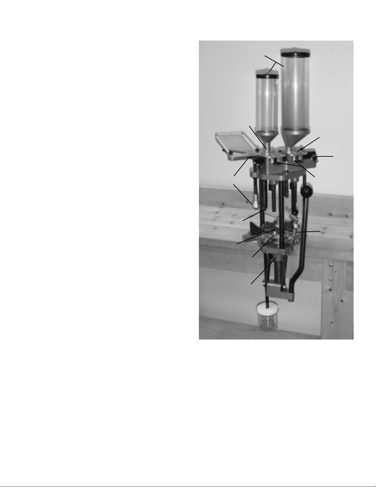
1 POWDER SYSTEM - Hull activated, no hull, no powder.
No need to manually turn powder on and off. No spillage of
powder can occur.
2 SHOT SYSTEM - Hull activated, no hull, no shot. No need
to manually turn shot on and off. No spillage of shot when
problems occur.
3 CASE HOLDERS - Easy removal of hull at all stations.
Universal 12 and 20 gauge case holders allows cases to
be sized down around the rim.
• The combination of the Powder System, Shot System and
the Case Holders allows the user to reload one shell
without fear of spillage.
4 PRIMING SYSTEM - Allows only one primer to feed at a
time and is an extremely reliable primer feed system.
5 STEEL SIZE RING - Provides complete resizing of high
and low base hulls. Not found in most presses.
• AUTO INDEX - Simple and very reliable automatic indexing
system that can be easily removed for manual indexing.
6 TILT-OUT WAD GUIDE - For easy and convenient feeding
of wads.
• MASSIVE FRAME - With compound leverage for smooth
solid feel.
7 QUICK DRAIN SYSTEM - Both powder and shot hoppers
have three locating positions. Off, on, and a forward drain
position for quick and convenient removal.
8 QUICK CHANGE - Of powder and shot bushings. Changes
over in less than one minute.
9 POWDER CHARGE - Is easy to check because the powder
station is directly in front of the press and it is easy and
convenient to remove the powder charge hull.
10 LARGE OPEN FRAME - Designed for convenient easy
access to all 8 stations.
• EASY CONVERSION - Changing from 12 gauge to 20
gauge is quick and easy with our convenient conversion kit.
11 SHOT & POWDER HOPPERS - Holds 25 pounds of shot
and 1 pound of powder.
THE “GRAND”
11
1
2
4
5
9
3
10
7
6
8
89001 THE GRAND, 12 ga. Shotshell Press
89003 THE GRAND, 20 ga. Shotshell Press
89005 Shotshell Press Conversion Kit, 20 ga.
89007 Shotshell Press Conversion Kit, 12 ga.
89010 Riser Stand
89100 Charge Bar
For shot and powder bushing
information see page 14.
Page 4
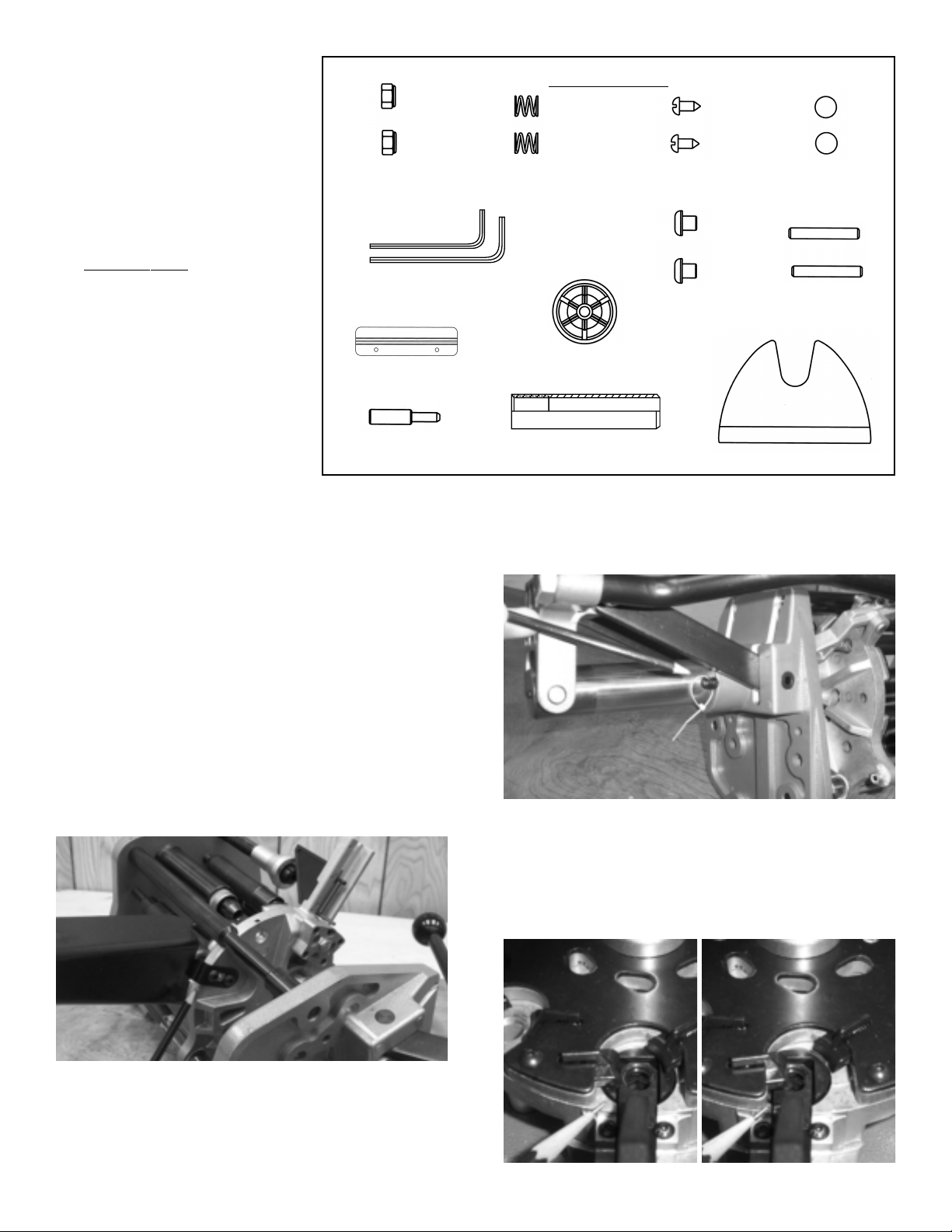
UNPACKING THE GRAND
A. Shot Hopper
B. Spent Primer Tube Assembly
C. Powder Hopper
D. Drain Tube (Clear Rubber Hose)
E. Press Assembly
F. Wad Box
Video
Wad Box Bracket
Discharge Chute
Primer Tray
Bag 1, P
#
8 x 3/8 Wood Screw
1/4-28 x 1/4 BHCS
3/8 Detent Ball
Detent Spring
Shotshell Crimp Starter 12 Ga., 6 Pt
Shotshell Primer Shut Off Pin
10-24 x 1-1/4 SHSS
10-24 Nyloc Nut
Shotshell Press Powder Baffle
Hex Wrench, 5/32
Hex Wrench, 3/32
arts List
10-24 NYLOC NUT
189063
ALLEN WRENCH 3/32, 109635
ALLEN WRENCH 5/32, 181150
WAD BOX BRACKET
789013
PRIMER SHUT OFF PIN
789039
BAG 1 PARTS
DETENT SPRING
187153
CRIMP STARTER 12 GA., 6PT
189020
LOWER SHOT TUBE - LONG, 12 GA.
789100
#8 X 32 WOOD SCREW
189064
1/4-28 X 1/4 BHCS
189073
3/8 DETENT BALL
187152
10-24 X 1-1/4 SHSS
189062
POWDER BAFFLE 189037
Your Grand is set up at the factory for the following loads:
12 GA. LOAD INFORMATION
Federal Gold Medal 23/4"
452 powder bushing, CCI 209M primer, Federal 12S3 wad,
1
/8oz.#71/2shot bushing
1
hull, 17.5 gr. Red Dot,
20 GA. LOAD INFORMATION
Winchester 23/4" hull, 16.0 gr. Unique, 381 powder bushing, CCI
209M primer,Winchester WAA20 wad,
A Hydraulic conversion unit is also available for The Grand
shotshell press. For pricing and information, contact RCBS
direct at 1-800-533-5000.
As you remove press from box, take caution not to lay press
against primer channel.
that the primer channel extends upward as shown below. Lay
press on opposite side so that the primer channel extends
upward as shown.
(photo 1)
7
/8oz #71/2shot bushing.
Lay press on opposite side so
➞
After laying press on bench, remove plastic tie securing the
Lockout pin to the Ram of the press and remove Lockout pin.
(photo 2)
included), to secure press when not in use.
The Lockout pin can be used with a small lock (not
2
CAUTION: SHELL PLATE POSITION
Care must be taken that the shell plate is always in the
proper position.
cycling.
Press must never be partially indexed, this results in damage
to the Case Holders. Rotate Shell Plate and feel for Index Ball
to position properly.
(photo 3)
right
Check index position before
wrong
1
3
4
1
Page 5

PRESS MOUNTING
Step 1 Attach Discharge Chute to the bottom of the Shell
Plate Holder as shown in photo 1. Use two 1/4-28 x
Button Head Cap Screws and 5/32 hex wrench.
Step 2 Mount your press to a solid bench. Presses mounted
to a weak or flexible bench are a safety hazard and will not
produce a consistent loaded round. The Grand press is
designed with two sets of mounting holes, three larger holes
(two of these holes for mounting to an optional RCBS
Accessory Base Plate-2 part number 09280) or four small
holes for the optional RCBS Riser Stand part number 89010.
1
/
4
5
Select an area on your bench with approximately one-foot
clearance on each side of The Grand. Install press with three
3
/8" bolts or four 1/4" bolts, length to be determined by the
thickness of your bench (mounting hardware not included).
The press can also be mounted on our optional Riser Stand,
which raises the press four inches above your bench (Riser
Stand part number 89010)
The front edge of your bench must have a minimum of 11/2" of
clearance to allow the press handle to cycle completely. The
optional Riser Stand angles forward off your bench to allow the
complete cycle of the press handle. Insure that the toggle
block does not strike the face of your bench.
(see photo 6).
LOADED ROUND CONTAINMENT
For presses mounted directly to the bench, you may want to
drill a 3" hole just off the end of the Discharge Chute and
catch your loaded rounds beneath the bench.
7
Use of the optional Riser Stand allows the loaded rounds to
drop into a container on top of the bench (Riser Stand and
container not included).
8
POWDER AND SHOT SYSTEM
The Grand 12 gauge comes with one #452 powder bushing
1
and a 1
with one
To change bushings, before powder and shot are added, just
remove charge bar locking pin
bar to the right. This allows the removal of the charge bar to
change bushings
/8oz.#71/2shot bushing. The 20 gauge Grand comes
#
381 powder bushing and a 7/8 oz.#71/2shot bushing.
(photo 10)
(photo 9)
.
and slide the charge
6
9
10
2
Page 6
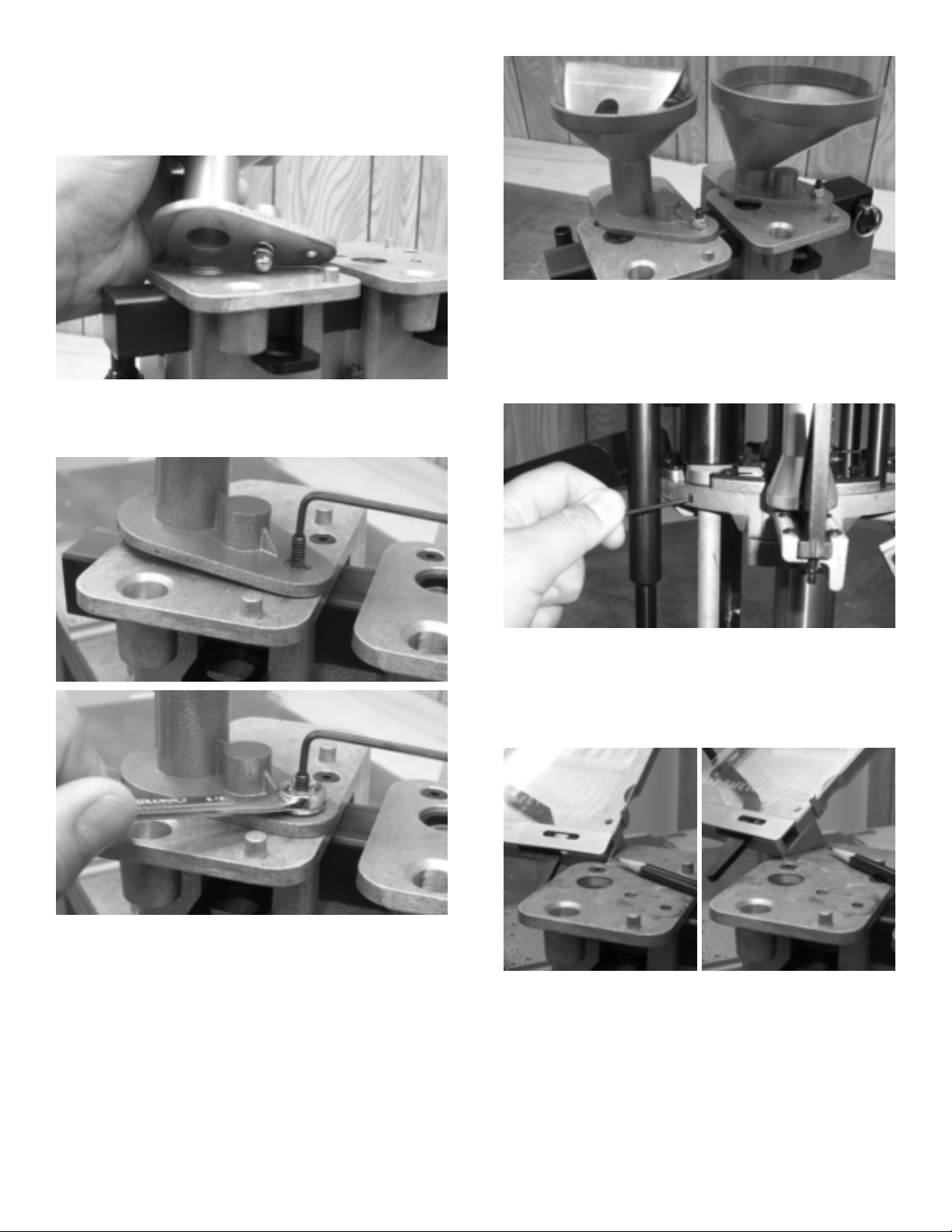
INSTALL POWDER AND SHOT HOPPERS
The Powder Hopper (smaller diameter tube) is to be mounted on
the left and the Shot Hopper (larger diameter tube) on the right.
Install detent spring then ball into hopper funnel assembly and
install on the press as shown in photo 11.
11
1
Install 10-24 x 1
base and into the top of the shut off plate. Install 10-24 Nyloc
nut to secure hopper funnel base to top of press. Use 3/32 hex
wrench and 3/8 wrench (not provided).
/4" set screw securely through hopper funnel
➞
14
Note: In OFF position
INSTALL SPENT PRIMER TUBE ASSEMBLY
Raise ram to the top of the press stroke and install the tube as
shown in photo 15. Tighten the setscrew to secure the tube.
Do not over tighten, use 3/32 hex wrench.
12
13
Funnels must be tightly secured but be able to pivot between
OFF, ON and DRAIN positions. Install powder baffle through
the top of the powder hopper as shown in photo 14.
15
INSTALL PRIMER TRAY
With ram still raised to the top of the press stroke, place Primer
Tray on Primer Tube as shown in photo 16. Primer Tray is held
in place by its own weight. Primer Tray body is to the left of the
Powder Shut Off Plate and does not ride on top of the plate
(photos 16 & 17)
right
.
16
wrong
17
3
Page 7

Install Wad Box Bracket approximately six inches from the
right side of the press to provide clearance between the
handle and the box
be flush with the bench top. Attach using the two 8x32 Wood
Screws provided. Hang Wad Box on Bracket.
(photo 18)
. The top of the Bracket should
18
PRESS FUNCTIONS BY STATION
The Grand is an eight-station auto indexing progressive
shotshell reloader. All functions occur on the upstroke of the
Ram with the exception of indexing, which occurs on the down
stroke of the Ram. The Index Arm may be removed for manual
indexing of the press.
STATION 1
Full length resizing and spent primer removal. Resizing is
accomplished with a steel sizing ring
(photo 20)
.
Install Primer Shut Off Pin into Primer Tray (
Assembly is complete.
➞
photo 19)
.
20
STATION 2
Priming. Primers are fed from the Primer Tray to the Primer
Drop Tube
(photo 21)
.
21
Primer is dropped from the Primer Drop Tube Collet to the
Primer Transfer Bar
(photo 22)
.
19
22
4
Page 8

Primer Transfer Bar delivers the primer to the primer station
(photo 23)
.
STATION 5
Shot Drop and Wad Seating. Case activated, will not drop a
shot charge without a hull with a wad present. Drop Tube (A),
driven by the bottom of the wad cup, drives the Shot Shut Off
gate (B) to drop the shot charge
present or a hull with no wad
assembly does not activate the Shot Shut Off gate. The Wad is
seated at the top of the stroke.
(photo 26)
(photo 27)
. If no hull is
, the Drop Tube
➞
23
Primer is seated at the top of the stroke.
STATION 3
Powder Charge. Case activated, will not drop powder if a hull is
not present. Drop Tube (A) drives the Powder Shut Off gate (B)
to drop the powder charge
Drop Tube assembly does not activate the Powder Shut Off gate.
(photo 24)
B
. If no hull is present, the
➞
➞
A
24
STATION 4
Wad insertion
(photo 25)
.
A
B
➞
26
➞
27
NOTE: No wad present.
STATION 6
Crimp Start. An 8 point Crimp Starter is installed at the factory
(photo 28)
accessory box.
. A 6 point Crimp Starter is included in the
25
28
5
Page 9

STATION 7
Crimp. The Crimp Die is pre-adjusted for Federal Gold Medal
Hulls with a Federal 12S3 wad
other components may require adjustments.
(photo 29)
. NOTE: The use of
29
STATION 8
Final Crimp. Removes “nail head.” Loaded round is radiused
(tapered) at the nose at the top of the downstroke
and ejected at the end of the upstroke as the Case Holder
Plate indexes
(photo 31)
.
(photo 30)
30
FILL POWDER AND SHOT HOPPERS
The next step is to load the Powder Hopper. The Powder
Hopper is the smaller diameter tube on the left. Be sure the
Hopper is in the ON (middle) position as shown in photo 32.
Remove the cap and pour the powder into the Powder Hopper.
The Powder Hopper will hold approximately one pound of
powder (varies based on powder type). After filling the Powder
Hopper, replace the cap.
31
DRY CYCLE PRESS
Before adding shot, powder and primers, take some time to
cycle a few hulls in the press. Advance the case from one
station to the next by cycling the press handle with a SLOW,
STEADY and COMPLETE
press indexes. The Grand press does not require a lot of effort
to index the press when returning the handle forward.
stroke. Get a feel for how easily the
32
Adding shot is the next step.The Shot Hopper is the larger
diameter tube on the right. Be sure the Hopper is in the ON
(middle) position. Remove cap and place a funnel (not included)
in the top of the Shot Hopper and pour the shot into the Shot
Hopper.The Shot Hopper will hold a full 25 pound bag of shot.
After filling the Shot Hopper, remove funnel and replace cap.
size shot is the largest shot size that The Grand will accommodate.
FILL PRIMER TRAY
Loading the primer tray is next. Insure that Primer Shut Off Pin
is installed into Primer Transfer Arm. Next, pull the press
handle all the way down (NOTE: Insure Case Holder Plate is
indexed properly). Lift the Primer Tray off the Priming Tube.
The Primer Tray can be laid flat on the bench for easy loading
of the primers. The front end of the Primer Tray that attaches
to the Drop Tube should extend beyond the edge of your
bench
(photo 33)
. This will allow the Primer Tray to lay flat.
#
5
CAUTION: Shell Plate must never be partially indexed, this
results in damage to the Case Holder Plate. Turn Case Holder
Plate and feel for index ball to position
When cycling the press, always use full stroke of the handle
and the Case Holder Plate will always properly align itself.
(see photos 3 & 4)
.
33
6
Page 10

Open the Primer Tray Lid. Place a sleeve of 209 primers
upside down on the Primer Tray. Slide the outer sleeve off to
the rear.You will need to slightly raise the outer sleeve to clear
the Primer Tray Lid. The primers will be properly oriented.
Properly close the Primer Tray Lid and replace Primer Tray
onto Priming Tube. (Tip: Drop four to five primers manually
into the Primer Drop Tube before installing the loaded Primer
Tray. This acts as a “reserve” supply should you have a primer
“bridge” in the Primer Tray during operation of the press.)
FILL WAD BOX
Fill wad box with appropriate type wads.
PRESS OPERATION – SINGLE ROUND
With your right hand on the Handle Ball, pick up an empty hull
with your left hand and insert into station 1 by sliding the hull
base flat on the Shell Plate Holder (A), under the two Case
Holders (B). The Case Holders will self-align the hull for the
sizing and spent primer removal operation
(photo 34)
.
Caution must be taken when loading one round at a time
with The Grand shot shell press. Press vibration causes
powder and shot to settle and pack into the charge
bushings. The powder and shot charges can be increased
by up to 12%. Do not use the first powder and shot charges
after several empty cycles of the press handle.
COMPONENT ADJUSTMENT SECTION
If using other than Federal Gold Medal 23/4" hulls, Federal
12S3 wads, CCI 209M primers, Alliant Red Dot powder or 1
1/8 oz of
necessary. If loading 3
removed and the press indexed manually.
1. Powder or Shot Bushing change Refer to section
2. Sizing The Grand is shipped with the Size Die adjusted for
#
71/2shot, a few simple adjustments may be
Powder and Shot Charge Bushing Change
proper hull ejection pressure. Rough handling during shipping
can cause this to change. If excessive pressure is felt during
resizing or hulls stick up in the Sizing Die please readjust.
Proper setting is with one to three threads showing. Simply
screw up or down the top portion of the Sizing Die
1
/2" hulls, the Index Arm must be
, page 9.
(photo 35)
.
B
➞
B
➞
A
34
Remove Primer Shut Off Pin from the Primer Tray and place in
hole in bottom left corner of the Primer Tray for storage.
Smoothly lower the Handle. This resizes and deprimes the hull
in Station 1. Raise the Handle completely, this will index the
hull to Station 2. Reinstall the Primer Shut Off Pin into the
Primer Tray, this prevents an excessive amount of primers from
being fed into the Primer Drop Tube.
Lower the Handle and this will prime the hull in Station 2.
Raise the Handle completely and index the hull to Station 3.
Make sure that your Powder Hopper is in the ON position.
Lower the Handle and the hull will actuate the powder drop
system allowing a charge to fill the hull. Raise the Handle
completely and index the hull to Station 4.
Place a wad into the Wad Guide of the tilt out Wad Guide
Carrier with your right hand and then lower the Handle. This
inserts a wad into the hull. Raise the Handle completely and
index the hull to Station 5.
Make sure that the Shot Hopper is in the ON position. Lower
the Handle, the inserted wad in the hull will actuate the shot
drop system allowing a shot charge to fill the hull. The wad is
also being seated at this point.
Lowering and raising the Handle three more times will start the
crimp, crimp, final (taper) crimp and eject the loaded round.
Notice the ease of loading just one round, powder and shot
are dropped only when a hull was present. You can continue to
practice one at a time or begin your continuos progressive
loading process.
35
3. Priming Station Adjustment The Primer Stem Assembly
is under spring tension to compensate for varying internal
base wad heights between hull manufacturers. Should it
become necessary to adjust primer depth, the Primer
Seater Body Assembly can be moved up or down. To make
this adjustment, loosen the top
up or down in
seating depth is achieved
1
/4turn increments until desired primer
3
/4" lock nut and screw rod
(photo 36)
.
36
7
Page 11

4. Powder Station Adjustment Once again, due to base wad
height, it may be necessary to adjust the Powder Drop Tube
to obtain proper Powder Shut Off Gate movement. With a
hull present and the Handle lowered, the Shut Off Gate
should be flush to
photo 37)
grasp the Upper Drop Tube with the fingers of one hand and
unscrew the Lower Drop Tube with the fingers of the other
hand
. To make this adjustment, with an empty station 3,
(photo 38)
1
/4" inset with the Top Plate casting
. Secure with brass lock ring.
(“A”
31/2" hulls, remove top lock nut (D) and socket head cap screw
on Wad Guide Arm and raise upper half of Wad Guide Arm.
Position upper half of Wad Guide Arm to clear the hull and
reinstall socket head cap screw and nut.You must also raise
the Wad Starter Rod. Due to shot cup length of some 1
and greater wads, you may have to manually insert wads. First,
remove the Wad Carrier arm and remove the Wad Guide.You
then place a wad into the Wad Guide and place over the hull
mouth. Cycle the press. The Wad Guide must then be removed
from the Wad Starter Rod and the process repeated.
1
/4oz.
➞
A
➞
37
D
➞
A
C
B
➞
➞
39
38
5. Wad Insertion Adjustment If wad petals contact Wad Starter
Rod (A), loosen nut (B)
petal clears, retighten nut. This prevents folding over of the
wad petal as it is inserted into the hull. If the Wad Carrier is
not centered over the hull, crushed hulls, damaged wads or
broken Wad Fingers may result. To center the Wad Carrier,
place a fired 2
shell plate holder assembly at station 3, this will prop up the
plate and more easily allow adjustment. Loosen the lower lock
nut on the adjustment set screw and adjust the set screw (C)
until the Wad Guide is centered to slightly forward under the
Starter Rod
3
/4" hull between the bottom casting and the
(see photo 39A)
(photo 39)
and adjust rod up until wad
, retighten lock nut. To load 3" or
39A
8
Page 12

6. Shot Drop and Wad Seating Station Adjustment
shot is the largest size The Grand will dispense. Larger shot
sizes must be weighed separately and manually put into the
hull prior to the Crimp Start station. Due to varying base wad
heights and design, as well as wad design, it may be
necessary to adjust the Lower Shot Tube to obtain proper
wad seating depth. Adjust by grasping the Upper Drop Tube
with the fingers of one hand and unscrew the Lower Drop
tube with the fingers of the other hand
brass lock ring. Shot Shut Off Gate movement will typically be
1
/4" out to all the way in. For 12 gauge hulls with tapered
from
internal bases such as Winchester AA red or gray, Remington
STS or Nitro 27, etc., a longer Lower Shot Tube has been
provided to achieve proper wad seating depth. (NOTE:
Improper wad seating depth will cause hull collapse/buckling
or crimp problems at Station 7).
For proper wad seating, 20 gauge loaders need to adjust a
1
gap of
tubes.
/4" to 5/16" between the Upper and Lower Shot Drop
(photo 40)
#
. Secure with
5 size
40
➞
C
42
9. Final Crimp Adjustment Final crimp is an up or down
adjustment to radius the end of the loaded round. Loosen
the top lock nut (D)
up or down and retighten lock nut.
10. Case Eject Adjustment The Press is preset for proper
case eject. Should adjustment become necessary, using a
5
/16" hex key wrench, loosen the socket head cap screw in
the top of the Eject Rod Holder, position the Case Eject
Arm to just clear the final crimp die and retighten the cap
screw. (CAUTION: Do not use the Case Eject Rod to try to
tighten the Eject Rod Holder!)
(see photo 41)
DRAIN SHOT AND POWDER HOPPERS
Place the flexible drain tube on the boss below the hopper you
wish to empty. Place a container beneath the drain tube. Rotate
the Hopper to the DRAIN position and the Hopper will empty in
a matter of seconds
(photo 43)
, adjust Final Crimp die
.
7. Crimp Start Adjustment Crimp start is an up or down
adjustment. Loosen the top lock nut (A) and adjust Crimp
Start assembly up or down, retighten lock nut
Too much Crimp Start can cause a bulge on the side at
the top of the hull during crimp. Not enough crimp start can
leave a hole in the center of your hull after crimp.
(photo 41)
D
➞
➞
A
8. Crimp Adjustment Crimp is also an up or down
adjustment. The crimp depth is controlled by loosening lock
(see photo 41)
nut (B)
up or down and retighten lock nut. If hulls bulge or collapse
during crimp, reduce crimping spring pressure. To reduce
crimp spring pressure, adjust nut (C)
the bottom of the Top Plate. If the crimp is concave or
dished, add spring pressure. If the crimp is peaked, reduce
crimp spring pressure and check that wad is seated to the
correct depth. (NOTE: If wads are not seated deep
enough, the shot column will be too high in the hull thus
causing problems with crimp.)
, adjusting the Crimp Die assembly,
(photo 42)
➞
➞
B
B
41
up towards
.
43
POWDER AND SHOT BUSHING CHANGE
The Grand shot shell press uses replaceable powder and shot
bushings to control charge weights. Carefully check the charge
weights thrown as they can vary based on powder type, age of
powder and type of shot used.
Empty charge bar for bushing change.To change Powder or
Shot bushings, but staying with the same type of powder and
size of shot, move Hoppers to the OFF position. If you are
changing type of powder or shot, DRAIN hoppers first. You must
then remove the powder and shot left in the Charge Bar. With the
press clear of hulls, place a fired hull in station 3 and a fired hull
with a wad in Station 5. Lower the Handle, dropping the charges
in the charge bar. Raise the Handle completely, remove the hulls,
empty hulls and replace back into Stations 3 and 5. Lower and
raise the Handle once more. Remove and empty the hulls. Your
Charge Bar is now cleared. Remove the Charge Bar locking pin
and the slide to the right allowing changing of the Bushings.
9
Page 13

(CAUTION: Be sure to support underneath the Charge Bar to
keep from dropping the Bushings out the bottom.)
Install appropriate Powder and Shot Bushings, the Shot
Bushing is the larger diameter of the two and should be on the
right side, reinstall the Charge Bar. (NOTE: The windows on the
Charge Bar allow you to see what type of bushings that you
have installed, the windows should face the front of the press.)
Reinstall Charge Bar Locking Pin through the Index Shaft
Bracket and Charge Bar. (NOTE: Lowering the Handle slightly,
allows movement of the Push Rod, allowing the Locking Pin to
be installed through the Index Shaft Bracket easier.)
TROUBLESHOOTING
1. Hulls:
Split or crushed hulls are not to be used. Out of round
hulls may catch on Size Ring or Primer Seat Die. Return to
round before using.
2. Indexing:
The Case Holder Plate indexing is set at the factory. Should
adjustment become necessary, adjust the adjustment screw
up or down. Indexing can be affected if errant shot finds its
way into the Case Holder Plate or under the Indexing Arm
(see photo 44)
.
45
5. Primers do not transfer from Primer Tray to Drop Tube:
Remove Lock Pin from Primer Tray.
Primer Tray may not be seated properly on Drop Tube.
photos 16 & 17
Charge Bar not making full and proper travel. The Handle
is not being cycled completely or check Index Shaft and
Brackets for wear or looseness.
Broken Primer Transfer Arm. (see
6. Primer Tray fell off press:
Improperly seated or the Primer Shut Off Pin was not
inserted when single rounds were loaded. If the Primer Shut
Off Pin is not inserted, primers will continue to feed into the
Drop Tube, the Drop Tube fills with primers (@25) and works
the Primer Tray up and off the press
.
#
7 below)
(see photo 46)
See
.
44
3. Adjusting the upper bushing of the size die will increase or
decrease the amount force used to push the hull from the
Size Die. Adjust so you feel the minimal amount of force to
size but enough to eject the spent primer and push the hull
from the Size Ring.
4. Hull stuck in the Size Die:
Typically not enough spring pressure. Adjust the upper
bushing of the Size Die down to push the hull from the Size
Die. High base brass may require more hull ejection spring
pressure. If hull ejection pressure is at a maximum setting
and the hulls continue to stick in the Size Die, inspect Case
Holders for damage or this may be a sign that there is base
wad separation in the hull. Inspect the offending hull, if base
wad separation is noticed, discard hull. CAUTION: If this hull
is loaded, the base wad may separate when fired and lodge
in the barrel causing damage to the firearm and potential
injury to the shooter.
(see photo 45.)
We’re here to help!
If you have any questions, call RCBS Customer Service at
1-800-533-5000, Monday - Thursday, 6:30 a.m. to 3:00 p.m.
46
7. Primers found on top of press:
Broken Transfer Arm. This is usually caused when the Primer
Drop Tube is filled with primers and the top primer wedges
between the Transfer Arm and the Drop Tube.The Charge
Bar pushes the Transfer Arm to the left and breaks off the
right side that is contained inside the Primer Tray. With the
right side of the Transfer Arm broken off, primers will
eventually push out the broken piece and also fall out onto
the top of the press instead of down into the Drop Tube.
10
Page 14

8. Primers do not drop from Collet to Transfer Bar:
Check Collet for damage or burrs.
Check Primer Transfer Bar for damage or burrs.
Loosen lock nut (B) on the top of the Primer Drop Tube
and adjust down in
freely. Retighten lock nut
the Primer Drop Tube Assembly too far down may cause
damage to the Primer Transfer Bar.)
1
/4turn increments until primers drop
(photo 47)
.(CAUTION: Adjusting
B
➞
9. Primers drop from the Primer Transfer Bar before
reaching the end of its travel:
The Primer Sleeve in the lower casting may not have
returned upward. Foreign material may be lodged in the
assembly. Remove Primer Seater Casting, inspect for
damage, clean (or replace damaged parts) and reinstall.
10. Hulls stick below Case Holder Plate after priming,
causing press not to index:
Use of very low base brass hulls is typically the cause. The
Primer Seat Die outer body is clearing the Case Holders
before the brass portion of the hull is exposed. Loosen
Lock Nut (A) and lower outer die body down in
increments until problem solved
11. Hull mouths catch going into the Primer Seat Die:
Hulls are either not round or there is a slight die body
alignment problem. Return hull mouth to “round” condition.
To realign, remove primers, insert a hull in Station 2, loosen
lock nut (A,
into Primer Seat Die, with Handle at very bottom of stroke,
retighten lock nut (A).
photo 49
), lower Handle while guiding hull up
(photo 49)
1
/4turn
.
47
48
A
➞
12. Powder below the shell plate at Station 3:
Hull is missing primer.
Check to insure that primer supply has not run out.
Check for damage to Primer Transfer Bar that may cause
primers to drop in sideways onto Primer Seat Plug.
13. Inconsistent powder charges:
Foreign material may have made its way into the powder
bushing. We have seen strings from shot bags, seals from
the powder canister and pieces of plastic.
Lower drop tube may not be adjusted to basewad in hull to
provide full travel of Shut Off.
Index Shaft and Brackets may be worn or loose causing
the Charge Bar to not make complete left and right
movements.
14. Hulls pop out at Station 4 - wad insertion:
The Wad Guide is not returning up. Remove cap screw
and washer
see that the three springs are stacked properly. Check that
Wad Starter Rod is not adjusted too far up. If Wad Starter
Rod is too far up, it will not insert the wad past the Wad
Guide. The wad sticks in the Wad Guide and when the
Wad Carrier tips back, the hull is pulled from the press.
Adjust Wad Starter Rod to just clear wad petals as Wad
Guide tips inward.
(photo 50)
, remove Wad Guide and check to
49
11
Page 15

50
15. Wads crush hull mouths upon insertion:
Check Wad Guide for missing wad fingers. Replace if
fingers are missing.
Check alignment of Wad Carrier Arm. At the insertion
position, the Wad Guide should be centered to slightly
forward of center in relationship to the Wad Starter Rod
above it. See
16. Inconsistent shot charges:
Index Shaft and Brackets may be worn or loose causing
the Charge Bar to not make complete left and right
movements.
The Shot bushings were calibrated to soft lead shot.
Chilled or Magnum shot has a higher antimony content
and though the shot size may be
less mass for the same volume versus soft lead. Bushings
may be enlarged to drop a larger volume of shot or
sleeved to reduce the volume of shot.
17. Hulls collapse at Station 7 – crimp:
Wads are not seated deeply enough causing the shot
column to be too high. The crimp die cannot push the
crimp closed over the shot column, exerts excessive force
and collapses the side of the hull.
Too much crimp pressure, reduce crimp spring force.
#
5
(page 8)
of Component Adjustment section.
#
8 or #7.5 etc., there is
May be sporadic due to a damaged Case Holder, only
affects one of the eight case holder stations. If multiple
Case Holders are damaged, it will happen more frequently.
Damaged Case Holder(s) need to be replaced.
20. Hard ejection of loaded round at Station 8:
Typically caused by a damaged case holder. The Case
Holder does not retract causing extra force to be used to
eject round. If multiple Case Holders are damaged, it will
happen more frequently. Damaged Case Holder(s) need to
be replaced. Remove hulls from press. Using a
wrench, loosen socket head cap screw inside of Case
Eject Rod Holder
(CAUTION: Note position of Case Eject Rod, if it is not
positioned properly upon reattachment, damage may
occur). Remove Case Holder Plate Assembly by lifting
counter clockwise from Shell Plate Holder. Remove eight
8-32 button head cap screws with provided
off top plate, replace damaged Case Holders and
reassemble. Insure all Case Holders retract freely before
tightening the screws. Reinstall onto press ensuring Case
Eject Rod is in the correct position
(photo 52)
and remove from press
(photo 53)
5
/16" hex
3
/32" wrench. Lift
.
52
right wrong
18. Hull sticks up into Crimp Die at Station 7:
Crimp Die is adjusted down too far and/or Crimp Spring
force is excessive. Reduce spring pressure by backing off
nut above spring
seated deeply enough
high, not allowing for proper crimp.
Case Holders may be damaged and must be replaced.
19. Hull sticks up into Taper Crimp Die at Station 8:
Excessive taper crimp being applied-loosen top lock nut
and raise die.
Or as above, improper wad depth, causing too high of a
shot column.
(See photo 42)
(Station 5)
. Also, if the wad is not
, the shot column is too
51
21. Case Eject Rod broken:
As above, the extra force necessary to eject the loaded
round with damaged case holders puts extra force on the
Case Eject Rod, causing it to break. Also, after removing
and cleaning under the Case Holder Assembly, the Case
Eject Holder was aligned improperly under a die station,
when the handle is cycled, the die breaks off the eject rod.
22. Powder or shot is dropped without a hull present:
Shut Off is stuck to the rear. Shut Offs, Charge Bar and
housing may need to be cleaned. Powder dust residue
may cause the Shut Off to bind. Also, If your shot is very
dusty, this also causes the Shut Off to bind.
RECLAIMED SHOT!
12
53
DO NOT USE
Page 16

MAINTENANCE
Three areas that require more frequent lube are the Shell
Plate Assembly,
Carrier and the
grease will suffice.
The Case Holder Assembly must be removed to properly
lubricate. Follow
on how to properly remove and replace the Shell Plate
Holder Assembly.
(photo 1)
(photo 3)
Troubleshooting #20, page 12
contact area of the
back Support Rod. Any light oil or
(photo 2)
for directions
A
Wad
4
1
5
B
B
2
C
3
Periodic cleaning of the Charge Bar channel, Shut Off channel
and Upper Drop Tube holes in the Upper Casting will lessen
down time due to damaged or worn parts.
To clean these areas, drain and remove Powder and Shot
hoppers. Drain Powder and Shot bushings and remove Charge
Bar. Remove the Powder and Shot Shut Off Plates. This allows
complete access to the areas that require cleaning. When
reassembling, make sure that the Shut Off Plates are on the
correct side. The Shot Shut Off Plate goes on the right side
and has a rubber washer installed in the hole. Also, make sure
that the extension in the back of the Shut Off is surrounded by
the return spring.
6
7
13
Page 17

89100 THE GRAND, Charge Bar
POWDER CHARGE WEIGHT IN GRAINS
GRAINS 14 15 16 17 18 19 20 21 22 23 24 25 26 27 28 29 30 31 32 33 34 35 36 37 38 39 40 41 42 43
Accurate Solo 1000 387 399 411 420 432 438 447 459 474
Accurate Solo 1250 369 384 396 408 420 429 441 453 459 471 480 492 501 510 516 525 537 543 555 558
Accurate No. 2 Improved 357 366 378 387 396 408 417
Accurate Nitro 100 375 387 399 411 423 435 447 456 465
DuPont 700-X 402 414 429 441 453 465 471 486 498
DuPont PB 366 390 402 414 426 435 447 456 465 474 486
DuPont SR 7625 345 381 390 402 414 426 438 444 453 462 474 486
DuPont 800-X 372 390 402 414 423 429 438 447 459 468 480 507 525 534 549 558
DuPont SR 4756 366 408 426 435 447 459 471 480 525 534 549 558 580 588
DuPont 4227 366 390 408 414 420 426 435 441 447 453 462 468 474 480 486 498
Alliant American Select 417 423 432 447 456 468 477 483
Alliant Red Dot & E3 405 423 438 453 468 480 489 498 510 519
Alliant Green Dot 390 405 420 435 447 456 468 480 492 501 513 522 534 549 558
Alliant Unique 354 369 381 393 405 414 423 435 444 453 465 474 483 492 501 510
Alliant Herco 369 381 393 405 414 426 438 450 462 471 477 489 498 513 522 531 549 558 564 573 588 594
Alliant Blue Dot 366 372 381 390 396 408 414 423 435 441 447 459 468 474 483 489 495 501 510 516 522 531 534 543 549 555
Alliant 2400 291 300 312 324 330 339
Hodgdon Clays 429 441 456 468 483 495 507
Hodgdon International 375 390 402 414 423 435 447 459 471 483 495 507
Hodgdon Universal 342 354 366 378 390 402 411 420 429 438 447 456 468 480 489 501
Hodgdon HS-6 300 309 318 327 336 345 357 360 366 375 381 387 393 402 408 414 423 429
Hodgdon HS-7 318 330 339 348 357 363 369 378 384 390 396 405 411 417 423 429 438 444 450
Hodgdon Titewad 384 396 408 420 432 441 453 462 474 486 492
Hodgdon Longshot 300 309 318 330 345 348 357 366 372 381 390 396 405 414 423 429 435 444 450 459 465 471 480 486 492 498
Hodgdon Titegroup 324 330 343 351 360 369 378 387 396 405
Winchester 540 300 309 318 327 336 345 360 366 381 402 408 414 423 429 435 441 444 450 459 465 471
Winchester 571 318 390 396 423 429 438 444 450 456 462 468 474 480 486
Winchester Super Target 414 429 438 450 459 471 480
Winchester Super Lite 345 354 363 372 381 390 402
Winchester Super Field 327 345 354 420 426 432 441 450 456 462
HOW TO SELECT BUSHINGS FOR HALF GRAIN CHARGES:
Powder bushings are identified by numbers that correspond to
the size of their inside diameter. (For instance, the inside
diameter of the #456 bushing is .456 inches.) Bushings for
powder charges in half-grain increments can be calculated from
this chart. Simply “split the difference” between the two evengrain bushings, and select the bushing nearest the result.
Example: To find the bushing for 18 1/2 grains of Alliant Red
Dot powder, note that bushing #468 gives a charge of 18 grains
THE GRAND, Powder Bushings
Part Number Bushing# Part Number Bushing# Part Number Bushing# Part Number Bushing#
89111 354 89119 408 89127 438 89135 462
89112 360 89120 414 89128 441 89136 465
89113 366 89121 420 89129 444 89137 468
89114 372 89122 423 89130 447 89138 471
89115 381 89123 426 89131 450 89139 474
89116 390 89124 429 89132 453 89140 480
89117 396 89125 432 89133 456 89141 486
89118 402 89126 435 89134 459 89142 498
THE GRAND, Lead Shot Bushings
For Field Loads #6’s
Compensates for tighter packing
of smaller shot size.
Part Number Bushing Description
89170 7/8 oz.
89171 1 oz.
89172 1-1/8 oz.
89173 1-1/4 oz.
89174 1-3/8 oz.
89175 1-1/2 oz.
INTERCHANGEABLE
CHARGE BUSHINGS
For use with THE GRAND
shotshell reloader.
Designed so shot and
powder bushings cannot be
accidentally reversed in the
charge bar. The bushings
make it easy to change
from one load to another.
14
and that bushing #480 gives 19 grains. Split the difference
between 468 and 480, and the result is 474. Thus, the correct
bushing for 18 1/2 grains of Red Dot is bushing #474.
All charges listed on this chart are an average of several loads,
weighed following the complete reloading cycle. Powders used
in establishing these loads were from ballistic samples supplied
by the manufacturer or sealed tins of recent manufacture.
Charges may vary slightly due to operator's technique and/or
powder variables.
THE GRAND, Lead Shot Bushings
For Target Loads
Calibrated to measure maximum legal loads
for trap and skeet shooting.
Part Number Bushing Description
89188 7/8 oz. #9
89189 1 oz. #7-1/2
89190 1 oz. #8
89191 1-1/8 oz. #7-1/2
89192 1-1/8 oz. #8
89193 1-1/8 oz. #8-1/2
89194 1-1/8 oz. #9
Page 18

# Description Part # Qty
THE GRAND PARTS LIST • NOVEMBER 2003
1 SS Frame 789000 1
2 SS Top Plate 789001 1
3 SS Support Rod 789023 2
4 SS Support Rod Turned 789031 1
5 3/8-16 x 1 Flat Head Cap Screw 188750 3
6 Link Pin Left 788258 1
7 Link Pin Right 788257 1
8 SS Ram 789020 1
9 Detent Ball 187152 3
10 Detent Spring 187153 3
11 1/4-28 x 3/8 Socket Head Set Screw 187219 1
12 SS Lock Out Pin 789022 1
13 Link 188719 2
14 SS Toggle Block 789002 1
15 7/16-20 Nyloc Nut 188108 2
16 Toggle Block Pin 788256 1
17 SS Ram Pin 789021 1
18 Handle 786862 1
19 Handle Ball 109121 1
20 5/8-18 Hex Nut 109136
21 SS Charge Bar 789018 1
22 SS Powder Bushing SEE CHART
23 SS Shot Bushing SEE CHART
24 SS Shut Off Plate Powder 789062 1
25 SS Shut Off Plate Shot 789010 1
26 Rubber Washer 189039 1
27 10-24 x 1/2 Flat Head Cap Screw 189077 4
28 10-24 x 1-1/4 Socket Head Set Screw 189062 2
29 10-24 Nyloc Nut 189063 2
30 SS Shut Off 189019 2
31 SS Spring 189061 2
32 SS Self Locking Pin 189036 2
33 8-32 x 1/4 Button Head Cap Screw 188041 10
34 SS Index Shaft Bracket 789006 1
35 8-32 x 3/4 Button Head Cap Screw 187221 1
36 8-32 Nyloc Nut 189078 1
37 SS Charge Bar Index Shaft 789047 1
38 SS Charge Bar Push Rod Upper 789045 1
39 1/4-28 Hex Nut 109604 1
40 SS Charge Bar Push Rod Lower 789046 1
41 1/4-20 Nyloc Nut 189072 1
42 3/16 x 1 Clevis Pin 189038 1
43 SS Index Arm 789009 1
44 SS Powder Funnel 789011 1
45 SS Powder Hopper 189031 1
46 SS Powder Hopper Cap 189029 1
47 SS Powder Baffle 189037 1
48 SS Shot Funnel 789012 1
49 SS Shot Hopper 189030 1
50 SS Shot Hopper Cap 189028 1
51 SS Spent Primer Bottle Cap 789016 1
52 SS Decap Tube 789030 1
53 SS Spent Primer Bottle 189032 1
54 1/4-28 x 1 Flat Head Cap Screw 189075 3
55 1/4-28 Hex Nut 189604 2
56 SS 10/32 x 1/4 Socket Head Set Screw 109099 1
57 SS Spring 189055 1
58 SS Primer Seater Casting 189026 1
59 6-32 x 5/8 Socket Head Cap Screw 198964 4
60 1/4-28 x 1/2 Hex Head Bolt 189067 1
61 SS Primer Transfer Bar 789102 1
62 SS Spring 189054 1
63 1/8 x 1 Roll Pin 189079 1
64 6-32 x 1/4 Button Head Cap Screw 189066 6
65 SS Primer Sleeve 189025 1
66 SS Primer Plug 789034 1
67 SS Case Holder Plate 12 GA. 789004 1
67 SS Case Holder Plate 20 GA. 789110 1
68 SS Case Holder Top Plate Cap 789005 1
69 SS Case Holder 12 GA. 189015 16
69 SS Case Holder 20 GA. 789109 16
70 SS Spring 189052 16
71 8-32 x 5/16 Button Head Cap Screw 186147 9
72 SS Eject Rod Holder 12 GA. 789054 1
72 SS Eject Rod Holder 20 GA. 789119 1
73 SS Eject Rod 789055 1
74 3/8-16 x 1-1/2 Socket Head Cap Screw 189074 1
75 SS Shell Plate Holder 789003 1
76 SS Discharge Chute 789017 1
77 1/4-28 x 1/4 Button Head Cap Screw 189073 2
78 SS Green Wad Box 189033 1
Wad Carrier Assy 12 GA. 789078, 20 GA. 789132
79 SS Wad Carrier Bottom 789008 1
# Description Part # Qty
80 SS Wad Carrier Top 789007 1
81 5-40 x 3/4 Socket Head Cap Screw 189068 1
82 5-40 Hex Nut 189069 1
83 10-24 Hex Nut 189086 1
84 10-24 x 1-1/4 Socket Head Set Screw 189062 1
85 SS Spring 189058 1
86 SS Wad Guide 12 GA. 189016 1
86 SS Wad Guide 20 GA. 189017 1
87 SS Spring 189057 3
88 8-32 Flat Washer 189080 2
89 SS Primer Drop Tube Assy 789096 1
90 SS 5/8-18 Lock Ring 789059 1
91 SS Transfer Bar Actuator 789033 1
92 1/4-28 x 1/4 Socket Head Set Screw 189076 1
93 SS Primer Dispenser Collet 189024 1
Primer Tray Assy 789087
94 SS Primer Tray Bottom 189027 1
95 SS Primer Tray Frame 789014 1
96 10-32 x 1/4 Socket Head Cap Screw 187687 2
97 SS Primer Tray Base 789015 1
98 10-32 x 5/8 Socket Head Cap Screw 186624 2
99 SS Primer Feed Bar 189034 1
100 SS Spring 189061 1
101 SS Primer Shut Off Pin 789039 1
102 SS Primer Tray Lid 189035 1
Size Die Assy 12 GA. 789071, 20 GA. 789128
103 SS Size Die Bushing 789025 1
104 SS Spring 189053 1
105 SS Hull Extractor 12 GA. 789029 1
105 SS Hull Extractor 20 GA. 789112 1
106 SS Decap Rod Assy 789072 1
107 SS Size Die Body 789024 1
108 SS 1-3/8-12 Lock Ring 789058 1
109 SS Size Ring 12 GA. 789026 1
109 SS Size Ring 20 GA. 789111 1
Primer Body Assy 12 GA. 789074, 20 GA. 789129
110 1/2-13 Hex Nut 189081 2
111 Snap Ring 180052 1
112 SS Primer Body Bushing 789038 1
113 SS Primer Body 789037 1
114 SS Primer Stem Washer 789063 1
115 SS Spring 189056 1
116 SS Primer Stem Assy 12 GA. 789075 1
116 SS Primer Stem Assy 20 GA. 789130 1
Powder Tube Assy 789076
117 SS Upper Drop Tube 789101 1
118 SS Drop Tube Lock Ring, Brass 789056 1
119 SS Powder Tube Lower 789042 1
Shot Drop Tube Assy 12 GA. 789077, 20 GA. 789131
117 SS Upper Drop Tube 789101 1
118 SS Drop Tube Lock Ring, Brass 789056 1
122 SS Shot Tube Lower 12 GA. 789044 1
122 SS Shot Tube Lower 20 GA. 789115 1
Wad Starter
120 3/8-16 Hex Nut 189082 1
121 SS Wad Starter 12 GA. 789043 1
121 SS Wad Starter 20 GA. 789114 1
Crimp Starter Assy 12 GA. 789091, 20 GA. 789133
120 3/8-16 Hex Nut 189082 1
123 SS Crimp Start Rod 789048 1
124 SS Crimp Starter 12 GA. 8 POINT 189021 1
124 SS Crimp Starter 20 GA. 8 POINT 189023 1
125 SS Crimp Starter 12 GA. 6 POINT 189020 1
125 SS Crimp Starter 20 GA. 6 POINT 189022 1
126 8-32 x 1/2 Socket Head Cap Screw 187227 1
Crimp Closer Assy 12 GA. 789082, 20 GA. 789134
120 3/8-16 Hex Nut 189082 2
127 SS Crimp Closer Washer 789051 1
128 SS Spring 189059 1
129 SS Crimp Closer Sleeve 12 GA. 789049 1
129 SS Crimp Closer Sleeve 20 GA. 789116 1
130 SS Crimp Closer Plunger 12 GA. 789050 1
130 SS Crimp Closer Plunger 20 GA. 789117 1
Final Crimp Assy 12 GA. 789083, 20 GA. 789135
120 3/8-16 Hex Nut 189082 2
131 SS Final Crimp Rod 789052 1
132 SS Final Crimp Sleeve 12 GA. 789053 1
132 SS Final Crimp Sleeve 20 GA. 789118 1
133 SS Wad Box Bracket 789013 1
134 #8 x 1/2 Wood Screw 189064 2
Not Pictured
SS Drain Tube 789019 1
122 SS Lower Shot Tube - Long 789100 1
15
Page 19

16
Page 20

PRECISIONEERED®RELOADING EQUIPMENT
We think that we make the very best
reloading equipment in the world.
If you disagree, tell us - we want to do something about it!
If you agree, please tell your friends.
Customer Service
1-800-533-5000
(US or Canada) or
530-533-5191
Hours: Monday - Thursday, 6:30am - 3:00pm (hours may vary)
e-mail: rcbs.tech@atk.com • www.rcbs.com
RCBS • 605 Oro Dam Blvd. • Oroville, CA 95965
OUTERS • RAMLINE • ORBEX • FEDERAL
CCI • SPEER • RCBS
7201339/0205
 Loading...