

Page 1
R.A.S.S. BENCH
(Rapid Acquisition Shooting System)
PRODUCT INSTRUCTIONS
IMPORTANT
Page 2

IMPORTANT
Before using the RCBS R.A.S.S. Bench, read these instructions carefully to fully learn how to safely operate the related equipment.
Failure to properly operate certain equipment can result in severe personal injury and/or equipment damage.
If you have any questions while assembling or operating this product,
call us at 1-800-533-5000 or 1-530-533-5191
Monday – Thursday 6:30 a.m. to 3:00 p.m. Pacific Time
The instruction manual contains specific safety and operating information. It should be considered a permanent part of your
equipment and remain with the equipment at all times for easy reference.
LIMITED WARRANTY
Congratulations on the purchase of your new RCBS R.A.S.S. Bench. Your new unit is warranted to be free from defects in material or
workmanship for a period of TWO (2) years from the date of purchase. This warranty is extended only to the original consumer
purchaser. The R.A.S.S. Bench is designed to support shooter weight of 350 pounds or less. Should you believe that your R.A.S.S.
Bench is defective in material or workmanship, you must return it to Ammunition Accessories Inc. through its RCBS Operation,
postage paid, for evaluation. If defective, the product will be repaired or replaced at RCBS's option, at no charge. Please send a check
in the amount of twenty dollars ($20) U.S. payable to RCBS Operations for return shipping and handling, along with the unit to:
RCBS Operations, 605 Oro Dam Blvd., Oroville, CA 95965
Please complete the attached warranty registration card and mail this card to us at the above address within 30 days of purchas e.
Failure to send this card will not adversely affect your warranty rights if you can otherwise show in a reasonable way the date the
product was purchased (e.g. your dated purchase receipt). But sending this card is one convenient way to establish in our files the date
of purchase and will provide us with marketing information which should allow us to better meet your needs In the future.
THIS WARRANTY DOES NOT COVER DEFECTS OR DAMAGE RESULTING FROM: CARELESSNESS, MISUSE,
IMPROPER INSTALLATION, MODIFICATION, OR IF YOUR R.A.S.S. BENCH HAS BEEN ALTERED OR REPAIRED BY
ANYONE OTHER THAN FACTORY PERSONNEL, COMMERCIAL USE OR ACTS OF NATURE (i.e. fire or flood).
WARRANTY SERVICES CANNOT BE PROVIDED WITHOUT MEETING THE ABOVE REQUIREMENTS. Please retain this
warranty certificate for future reference.
THE IMPLIED WARRANTIES OF MERCHANTABILITY AND FITNESS FOR A PARTICULAR PURPOSE ARE LIMITED TO
THE DURATION OF THIS LIMITED WARRANTY. RCBS OPERATIONS IS NOT LIABLE FOR DAMAGES IN EXCESS OF
THE PURCHASE PRICE OF THE PRODUCT AND UNDER NO CIRCUMSTA NC E S SHALL RCBS OPERATIONS BE
LIABLE FOR CONSEQUENTIAL OR INCIDENTAL DAM AGE S. H O WEVER, SOME STATES DO NOT ALLOW
LIMITATIONS ON INCIDENTAL OR CONSEQUENTIAL DAMAGES, SO THE ABOVE LIMITATION OR EXCLUSION MAY
NOT APPLY TO YOU.
The above warranty provides the sole and exclusive warranty available to the customer in the event of a defect in material or
workmanship in the R.A.S.S. Bench. This warranty gives you specific legal rights, and you may also have other rights which vary
from state to state.
PRECAUTIONS
• Always wear eye and hearing protection when discharging a firearm. Shooter must maintain proper eye relief from optical
sighting devices and wear eye protection at all times.
• Target must have a safe backstop
• Bystanders must stay behind the shooters at all times
• Follow local, state and federal laws regarding firearm use
• The R.A.S.S. Bench is designed to support shooter weight of 350 pounds or less
ALWAYS FOLLOW THE RULES OF FIREARM SAFETY
2
Page 3

WARNING
: FIREARM RESTS ARE NOT INTENDED FOR USE IN OR ON ANY MOTORIZED VEHICLE OR TRAILER
UNLESS SECURED BY A PROPERLY DESIGNED MOUNTING SYSTEM AVAILABLE FROM THE MANUFACTURER.
FAILURE TO COMPLY WILL RESULT IN AN UNSAFE FIREARM CONDITION THAT MAY CAUSE PROPERTY DAMAGE,
PERSONAL INJURY OR DEATH.
WARNING
: UNLOAD FIREARM, OPEN FIREARM ACTION AND ENGAGE FIREARM SAFETY BEFORE USE WITH
FIREARM REST. DO NOT REACH IN FRONT OF FIREARM MUZZLE TO MAKE ADJUSTMENTS OR MANIPULATE
FIREARM REST. FAILURE TO COMPLY WILL RESULT IN AN UNSAFE FIREARM CONDITION THAT MAY CAUSE
PROPERTY DAMAGE, PERSONAL INJURY OR DEATH.
WARNING
: NEVER LEAVE FIREARM UNATTENDED ON FIREARM REST. FAILURE TO COMPLY WILL RESULT IN
AN UNSAFE FIREARM CONDITION THAT MAY CAUSE PROPERTY DAMAGE, PERSONAL INJURY OR DEATH.
WARNING
: NOT ALL FIREARMS WILL BALANCE ON FIREARM REST PROPERLY DUE TO UNUSUAL FIREARM
CONSTRUCTION AND THEREFORE SHOULD NOT BE USED ON FIREARM REST. FAILURE TO COMPLY WILL
RESULT IN AN UNSAFE FIREARM CONDITION THAT MAY CAUSE PROPERTY DAMAGE, PERSONAL INJURY OR
DEATH.
WARNING
: DISCHARGING SOME FIREARMS (DEPENDING ON CALIBER/RIFLE CONSTRUCTION) ON FIREARM
REST WILL CAUSE FIREARM MUZZLE TO MOVE VERTICALLY FROM REST POSITION AND/OR FIREARM REST TO
MOVE REARWARD. CARE SHOULD BE TAKEN TO ENSURE THAT FIREARM DOES NOT DISENGAGE FIREARM REST
OR THAT FIREARM REST DOES NOT LEAVE CONTACTING SURFACE. FAILURE TO COMPLY WILL RESULT IN AN
UNSAFE FIREARM CONDITION THAT MAY CAUSE PROPERTY DAMAGE, PERSONAL INJURY OR DEATH.
WARNING
: ALWAYS ENGAGE THE FIREARM SAFETY OR UNLOAD THE FIREARM BEFORE ADJUSTING.
ALWAYS KEEP FIREARM MUZZLE IN A SAFE DIRECTION WHEN PLACING FIREARM ON REST, ADJUSTING REST,
LOADING FIREARM, AND DISCHARGING FIREARM. CARE SHOULD BE TAKEN TO ENSURE THAT THERE IS NOT
INTERFERENCE WITH THE FIREARM STOCK, SLING OR ACTION. FAILURE TO COMPLY WILL RESULT IN AN
UNSAFE FIREARM CONDITION THAT MAY CAUSE PROPERTY DAMAGE, PERSONAL INJURY OR DEATH.
WARNING
: BEFORE USING, BE SURE BENCH LEGS ARE EXTENDED AS NECESSARY AND FOOT LEVELERS ARE
ADJUSTED TO PLACE THE BENCH IN A STABLE AND LEVEL POSITION. FAILURE TO COMPLY WILL RESULT IN AN
UNSAFE FIREARM CONDITION THAT MAY CAUSE PROPERTY DAMAGE, PERSONAL INJURY OR DEATH.
WARNING
: DO NOT SIT OR STAND ON THE RIFLE REST PORTION OR TOP OF THE BENCH. FAILURE TO COMPLY
WILL RESULT IN AN UNSAFE FIREARM CONDITION THAT MAY CAUSE PROPERTY DAMAGE, PERSONAL INJURY
OR DEATH.
WARNING
: MAKE SURE ALL FASTENERS ARE TIGHT BEFORE USING THE BENCH. FAILURE TO COMPLY WILL
RESULT IN AN UNSAFE FIREARM CONDITION THAT MAY CAUSE PROPERTY DAMAGE, PERSONAL INJURY OR
DEATH.
WARNING
: BEFORE MOVING, BENCH SHOULD BE BROKEN DOWN AND THE LEGS SECURED WITH THE
PROVIDED CINCH STRAP. FAILURE TO COMPLY WILL RESULT IN AN UNSAFE FIREARM CONDITION THAT MAY
CAUSE PROPERTY DAMAGE, PERSONAL INJURY OR DEATH.
WARNING
: BENCH IS DESIGNED TO SEAT ONE PERSON ONLY. MAXIMUM CAPACI TY IS 350 POUNDS. FAILURE
TO COMPLY WILL RESULT IN AN UNSAFE FIREARM CONDITION THAT MAY CAUSE PROPERTY DAMAGE,
PERSONAL INJURY OR DEATH.
WARNING
: USE CAUTION WHEN FOLDING AND UNFOLDING THE BENCH. FAILURE TO COMPLY WILL RESULT
IN AN UNSAFE CONDITION (PINCHING) THAT MAY CAUSE PROPERTY DAMAGE OR PERSONAL INJURY.
3
Page 4
UNPACKING
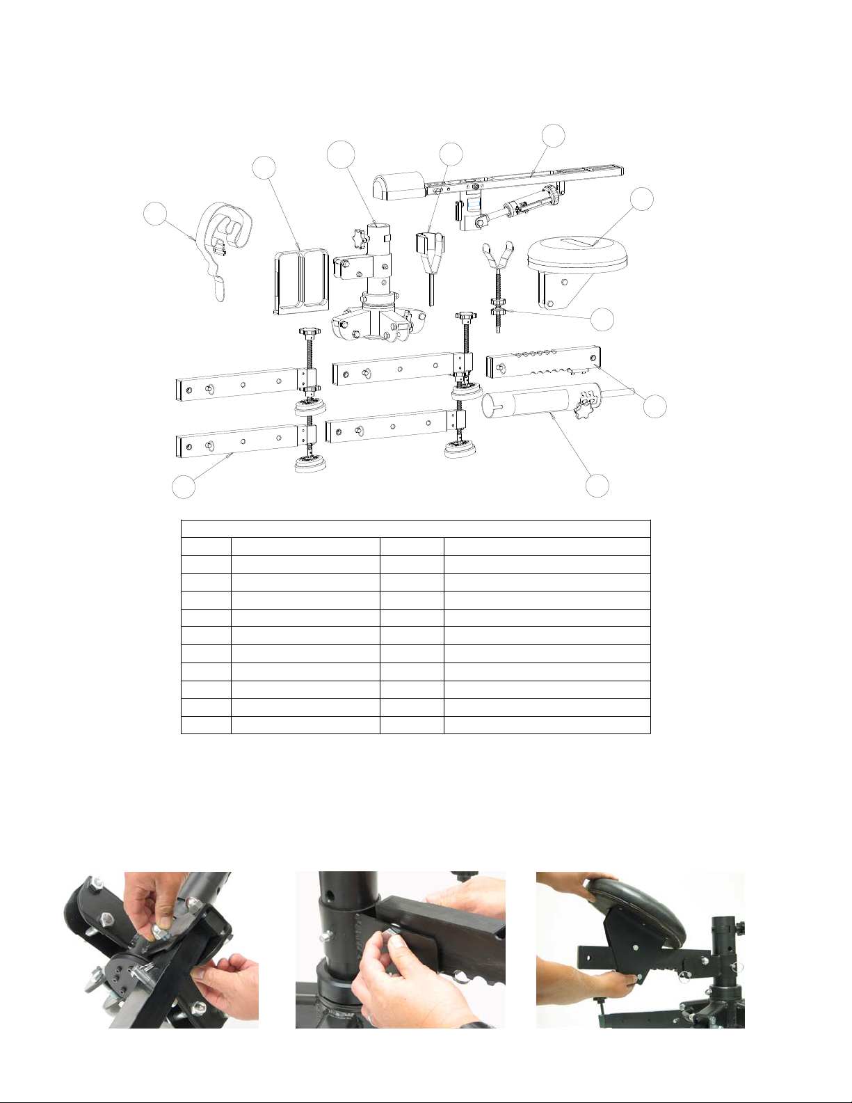
Open the box to remove, identify and layout the parts for assembly. To better understand these instructions, please refer to the parts
drawings found at the back of this manual.
7
1
10
2
6
8
4
9
4X
5
3
RASS Bench Assembly - Shipping
Item # Part # Quantity Description
1 180112 1 Ammo Tray
2 180127 1 Cinch Strap
3 CENTER_POST_ASSY 1 Rifle Rest Assembly
4 FRONT_CRADLE_ASSY 1 Front Rest Assembly
5 LEG_ASSY 4 Leg Assembly
6 REAR_CRADLE_ASSY 1 Rear Cradle Assembly
7 RIFLE_PLATFORM_ASSY 1 Rifle Rest Assembly
8 SEAT_ASSY 1 Seat Sub-Assembly
9 SEAT_BAR_ASSY 1 Seat Unit Assembly
10 SHAFT_HUB_ASSY 1 Shaft / Hub Assembly
ASSEMBLY
Place the steel Shaft Hub assembly in the middle of your workspace.
Using an 18mm or adjustable wrench (not included), remove the lower M12x1.75x60mm Hex Bolt and M12x1.75 Acorn Nut from the
Leg Assembly. Keeping the Leg Bushings in place, carefully slide the Leg assembly into the slot in the Hub. Align the holes and
reinstall the Hex bolt and Acorn Nut. Repeat the process for the other three Leg assemblies (see Photo 1).
Photo 1 Photo 2 Photo 3
4
Page 5

Remove the M12x1.75x60mm Hex Bolt and M12x1.75 Acorn Nut from the Seat Bar. Keeping the Bushings in place, place the Seat
Bar in the slot of Seat Collar. Align the holes and reinstall the Hex bolt and Acorn Nut (see Photo 2).
Remove the Quick Pin from the rear of the Seat Bar and slide the Seat onto the Seat Bar (see Photo 3). NOTE: The vertical portion of
the Seat Bracket is the ‘front’ of the seat. WARNING
: FAILURE TO INSTALL THE SEAT PROPERLY COULD CAUSE THE
SEAT TO TIP BACKWARDS. FAILURE TO COMPLY WILL RESULT IN AN UNSAFE CONDITION THAT MAY CAUSE
PROPERTY DAMAGE, PERSONAL INJURY OR DEATH. Reinstall Quick Pin.
Remove the Quick Pin securing the Seat Collar to the center Main Shaft and raise to the second highest position. NOTE: One hole will
be showing below the Seat Collar at this position (see Photo 4). Reinstall the Quick Pin.
Photo 4 Photo 5 Photo 6
Install the Center Post assembly and tighten the lower Knob to secure (see Photo 5).
Raise the Rifle Platform Adapter to the middle position by loosening the Knob, raising and rotating the Upper assembly and placing it
in the middle position (see Photo 6). Tighten Knob.
Loosen the Pivot Cam Lever and install the Rifle Rest assembly onto the Center Post assembly (see Photo 7) and tighten the Pivot
Cam Lever. Install the Rear Rifle Cradle and Recoil Strap into the center position and tighten the Locking Knob (see Photo 8).
Remove one Adjusting Knob from the Front Rifle Rest shaft. Slide the Front Rifle Rest assembly into the center slot of the Rest
assembly (see Photo 9). Install the second Adjusting Knob onto the Front Rifle Rest Shaft and secure.
Photo 7 Photo 8 Photo 9
The Neoprene padded Arm Rest is secured with hook and loop fasteners. It should already be installed on the Rest assembly but you
may need to readjust it for a proper fit. (see Photo 10).
Hook the Ammo/Case Tray onto the Rifle Rest assembly (see Photo 11).
Photo 10 Photo 11
5
Page 6

Your R.A.S.S. Bench is now assembled!
ADJUSTMENT
Your R.A.S.S. Bench is fully adjustable to fit most shooters. The seat height above ground is adjustable. The seat distance from the
center post is adjustable. Rifle torso height above the seat is also adjustable.
RCBS has found that the seat height adjustment of second from the top to be the most comfortable position for most shooters. If you
desire the seat to be higher or lower, support the Seat assembly and remove the Quick Pin and adjust the Seat Hub Bracket up or down
and reinstall the Quick Pin.
Adjust the Seat distance from the post to a comfortable position. To do this, tip the Seat forward towards the Center Post, press down
to disengage the bottom adjustment and slide forward or back. Return the Seat back to horizontal.
The Rifle Rest has been designed to fit most bolt action, lever action and semi-automatic rifles. There are three rear adjustment points
with 3” of vertical adjustment that allow you to place the butt of the rifle exactly where you want it. The Front Rifle Rest has 7” of
horizontal placement with 8” of vertical adjustment.
The Rifle Rest has been designed to allow you to cycle a lever action rifle without having to reposition the rifle. This same design
feature allows you to change magazines on semi-auto rifles without having to remove the rifle from the Rest.
Once you have adjusted the Rifle Rest to your rifle, you can adjust for torso height by, locking the Pivot Cam Lever, loosening the
upper knob, lifting and rotating the rifle rest and changing to a new position. RCBS has found the middle position to be the most
comfortable for most shooters. Individuals with a long or short torso may want to adjust up or down accordingly.
The Rapid Acquisition Lever allows you to rapidly adjust from a horizontal position to +/- 20 degrees. The fine adjustment knob
allows for precise vertical aiming (see Photo 12). WARNING
: THE RAPID ACQUISITION LEVER SHOULD NOT BE
ENGAGED UNLESS THE USER IS PROPERLY POSITIONED ON THE REST. FAILURE TO COMPLY COULD CAUSE THE
FIREARM TO FALL FROM THE REST CREATING AN UNSAFE FIREARM CONDITION THAT MAY CAUSE PROPERTY
DAMAGE, PERSONAL INJURY OR DEATH.
Photo 12 Photo 13
The Rifle Rest can rotate independently or with the Seat to allow for a 360 degree field of fire.
For independent turning of the Rifle Rest, loosen the Cam Lock Lever (see Photo 7). While seated, the Rifle Rest will now rotate
horizontally, without the Seat moving.
For combined rotation of the Rifle Rest and Seat, sit on the Seat and sight through the rifle. Lock the Cam Lock Lever. The Rifle Rest
will now rotate with the Seat around the centerline of the Hub.
The Legs of the R.A.S.S. Bench have three adjustment points. The innermost position is for storage and transport. The Legs should be
adjusted to the middle or extended position for greater stability remove the Quick Pin and adjust each Leg out to the desired position
and reinstall the Quick Pin.
TRANSPORT
The R.A.S.S. Bench can easily be broken down for transport. Remove and secure your unloaded firearm from the Rifle Rest. Remove
the Ammo/Spent Case Tray. Tighten the Cam Lock Lever, loosen the lower Center Support Knob and lift off the upper part of the
Rest as a unit. This unit can be further broken down by loosening the Cam Lock Lever and separating the Rifle Rest from the Center
Support. Adjust the Legs to the innermost position to minimize the size of the lower unit for transportation. Orient the Seat to the
opposite position of the Handle on the Lower Hub. Position the Seat to the furthest point away from the Center Post or you can
6
Page 7

remove it by removing the rear Seat Extension Quick Pin and sliding the Seat off. Remove the front Seat Extension Quick Pin to fold
down the Seat and reinstall the Quick Pin in place. Grasping the Handle on the Lower Hub and raising it upward will allow the Legs to
fold down on themselves. Secure the Legs with the provided Cinch Strap (see Photo 13). The R.A.S.S. Bench is now ready for
transportation to your favorite shooting or hunting spot.
Once you have arrived at your shooting or hunting spot, select the most level ground to shoot from. Place the Lower assembly in place
and remove the Cinch Strap. Remove the front Seat Extension Quick Pin, raise the Seat Extension and reinstall the Quick Pin.
Carefully unfold the Legs and adjust the Leg Extensions and Leveling Feet so that the Lower assembly is stable. Place the Center
Support onto the Lower assembly and tighten the Knob. Place the Rifle Rest onto the Center Pivot Rod and tighten the Cam Lock
Lever.
2
13
16
4
18
5
3
9
17
12
Shaft and Hub Assembly
10
7
2
11
3
7
1
14
15
2
3
6
8
Item # Part # Quantity Description
1 9320-10 1 Steel Hub Assembly
2 9320-100 9 M12x1.75x 60mm L Hex Bolt
3 9320-101 10 M12x1.75 Acorn Nut
4 9320-102 1 M12x1.75x110mm Hex Bolt
5 9320-105 1 1/2" x 1.9"L Quick Pin
6 9320-106 1 1/2" x 3.3"L Quick Pin
7 9320-107 5 M5x0.8 x 16mm S.H. Cap Screw
8 9320-119 4 Leg Support Block
9 9320-120 1 Wedge Bolt Assm.
10 9320-121 1 Shaft Lock Assembly
11 9320-14 1 Main Shaft
12 9320-15 1 Shaft Wedge
13 9320-17 1 Retaining Collar
14 9320-18 1 Bottom Cap
15 9320-19 1 M10x1.5 Thread Insert
16 9320-31 1 Steel Seat Collar Sub-Assembly
17 180106 2 Roller Bearing Assembly
18 180107 1 Thrust Washer
10
2
10
4
3
1
8
6
7
12
Item # Part # Quantity Description
1 9320-105 1 1/2" x 1.9"L Quick Pin
9
5
7
11
2 9320-117 1 3mm Spring Pin, Slotted
3 9320-21 1 Main Support Leg
4 9320-22 1 Leg Extension
5 9320-23 1 Foot Adapter Block
6 9320-24 1 Acme Rod Bushing
7 9320-25 2 M5x0.8 x 6.5mm L Skt Set Screw
8 9320-26 2 6mm Spring Pin, Slotted
9 180101 1 Acme Rod
10 180102 2 Leg Bushing
11 180103 1 Rubber Foot
12 180104 1 Knob
Leg Assembly
7
Page 8

5
4
1
Item # Part # Quantity Description
1 9320-105 1 1/2" x 1.9"L Quick Pin
3
6
2
7
2 9320-107 2 M5x0.8 x 16mm S.H. Cap Screw
3 9320-34 1 Adjustable Seat Support Beam
4 180102 2 Leg Bushing
5 180105 2 Tube End Cap
6 180121 1 RUBBER STRIP
7 187048 2 #10 FLAT WASHER (.203IDx.438ODx.063THK)
Seat Bar Assembly
9
6
3
4
Seat Assembly
Item # Part # Quantity Description
2
1 9320-103 2 M10 Nylock Hex Nut
2 9320-104 2 M10x1.5 Hex Bolt
3 9320-41 1 Seat
4 9320-42 1 Left Seat Bracket
5 9320-43 1 Right Seat Bracket
5
7
1
8
6 9320-45 1 Foam,2"thk,25.0 lbs/ft^3,55-75 IFD
7 9320-46 6 Wood Screw,#8x3/4"L,Zinc Plated Steel
8 180108 2 Seat Bolt Sleeve
9 1 Vinyl Material
8
9
7
2
1
5
Center Post Assembly
Item # Part # Quantity Description
4
3
1 9320-107 1 M5x0.8 x 16mm S.H. Cap Screw
2 9320-111 1 M12x1.75 Nylock Hex Nut
3 9320-120 1 Wedge Bolt Assm.
4 9320-15 1 Shaft Wedge
5 9320-19 1 M10x1.5 Thread Insert
6 9320-95 1 Shaft Extension
7 9320-96 1 Rifle Platform Adapter
6
8 9320-97 1 Shaft Adapter Rod
9 180109 1 3/4" Nylon Shaft Washer
8
Page 9
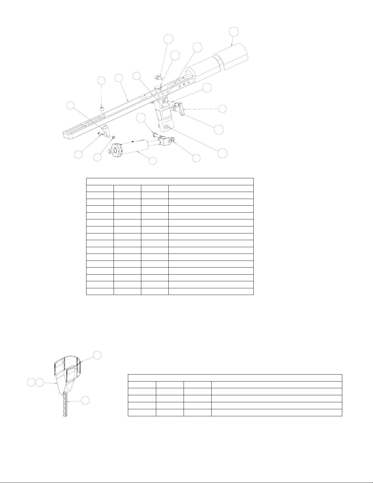
15
13
12
14
6
9
2
10
8
11
4
3
5
1
7
12
12
Rifle Rest Assembly
Item # Part # Quantity Description
1 9320-103 2 M10 Nylon Insert Lock Nut
2 9320-108 1 M10 x 1.5 x 20 S.H. Cap Screw
3 9320-112 1 M6x1 Nylon Insert Lock Nut
4 9320-115 1 M6x1 x 30mm Shoulder Bolt
5 9320-50 1 Rapid Acquisition Unit
6 9320-60 1 Mount Block Assembly
7 9320-65 1 Spud Handle
8 9320-98 1 Front Clevis Mount
9 9320-99 1 Rifle Platform
10 180110 1 M10x1.5 Shoulder Bolt
11 180111 1 M10x1.5 Shoulder Bolt
12 180113 6 Nylon Washer
13 180120 1 M10x1.5 Thumbscrew
14 180122 1 Plug
15 180125 1 Arm Rest Pad
3
4
2
Item # Part # Quantity Description
Rear Cradle Assembly
1 9320-81 1 Adjustable Rod
1
2 9320-82 1 Rear Cradle
3 180124 1 Recoil Strap
4 1 Polyester Velcro (Loop Only), Adhesive Backed
9
Page 10

2
3
1
Front Cradle Assembly
Item # Part # Quantity Description
1 9320-73 2 Adjusting Knob
2 9320-74 1 Front Cradle
3 180101 1 Acme Rod
Rapid Acquisition Unit
Item # Part # Quantity Description
1 9320-108 1 M10 x 1.5 x 20 S.H. Cap Screw
2 9320-109 1 M4x0.7x30 S.H. Cap Screw
3 9320-110 1 M4x0.7x20 S.H. Cap Screw
4 9320-114 2 M4x0.7 Nylon Insert Lock Nut
5 9320-116 4 M4x0.7x10 Flat S.H. Cap Srew
6 9320-118 1 Fine Adjustment Rod Assm.
13
9
15
14
5
12
6
10
11
3
4
7
1
8
2
7 9320-51 1 Clevis Mount
8 9320-52 1 Coarse Adjustment Rod
9 9320-53 1 Coarse Adjustment Lever
10 9320-90 1 Half-Nut Assembly
11 180114 1 Ram Cylinder Assembly
12 180115 1 Fine Adj. Nut Assm.
13 180117 2 Nylon Washer
14 180118 1 Spring
15 180126 1 Fine Adj. Nut Washer
2
1
3
Mount Block Assembly
Item # Part # Quantity Description
1 9320-61 1 Mount Block
2 9320-63 2 Nylon Sleeve
3 9320-66 1 Tension Block Assembly
10
Page 11

DETACH AND PLACE IN ENVELOPE
____________________________________________________________________________________________________________
Complete all sections
Mail to:
RCBS Operation
R.A.S.S. registration
605 Oro Dam Blvd.
Oroville, CA 95965
1. Where Purchased:_______________________________________________________________________
2. Name: Mr/Ms.____________________________ _____________________________________________
3. Street Address:_________________________________________________________________________
4. City, State, ZIP:_____________________________________________________________________ ___
5. Product Purchased:________
6. Date Purchased:________________________________________________________________________
Please enclose a copy of the original Register Receipt
09320 R.A.S.S. Bench________________________________________
11
Page 12

PRECISIONEERED RELOADING EQUIPMENT
We think that we make the very best reloading equipment in the world. If you agree, please tell your friends. If you
disagree, tell us we want to do something about it!
Customer Service
1-800-533-5000 (US or Canada) or 530-533-5191
Hours: Monday - Thursday, 6:30am - 3:00pm Pacific Time
(hours may vary)
e-mail: rcbs.tech@atk.com or visit our website at www.rcbs.com
RCBS 605 Oro Dam Blvd. Oroville, CA 95965
ALLIANT POWDER - CCI - CHAMPION TRAPS & TARGETS
ESTATE CARTRIDGE - FEDERAL AMMUNITION - FUSION AMMUNITION
GUNSLICK - ORBEX - OUTERS - RCBS - RAMLINE
SHOOTERS RIDGE - SPEER - WEAVER
12
 Loading...