

Page 1
PRICE 0NE DOlLAR
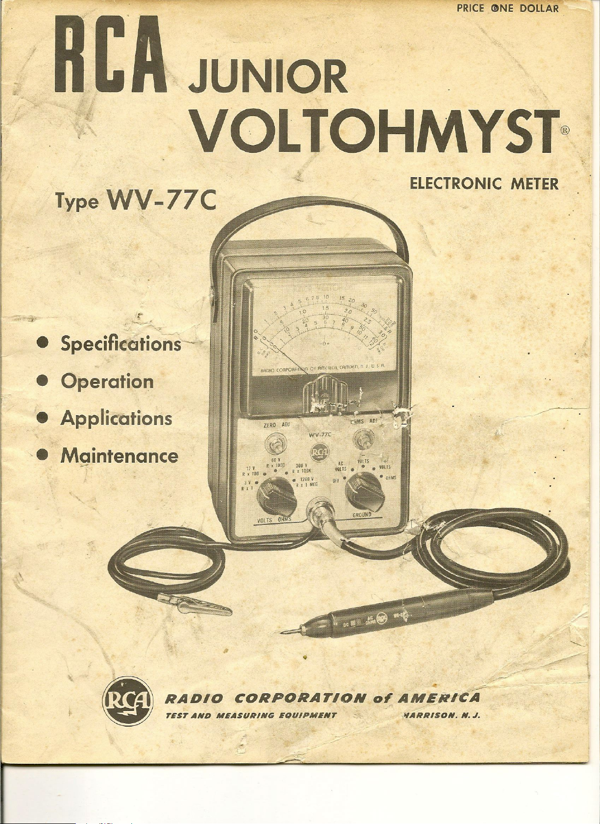
Type WV-77C
r
~:..
".-:.
.~
• SpecifkatioriS~
JUNIOR
,
VOLTOHMYST®
ELECTRONIC METER
• Operation
• Applications
'. Maintenance
--
ZfRO AUI
~ WV_77C
..;:~s
AOJ~· ~).
..
~"
"
i~ ,~ ~
V ~.' \~)'
6QV ~'
12 V R ~ fOOQ
R , 1D~. • • R. 1001( VOLTS.·. VOlTS
JOD
v
.IZOOV Off .~. 0 liS
~ , 1 NEG H
At VDtTS -
+'
•
,
~~-
RADIO CORPORATION
TEST AND MEASURING EOUIPMENT ~ ,"ARRISON_ N.
0'
AMEN-rCA
,
y---
J.
Page 2
Safety Precautions
The metal case of this instrument is connected to
the ground of the internal circuit. For
tion, the ground cable of the WV-77C should always be
connected to the ground of the equipment uncler test.
The WG-299B DC/AC-Ohms Probe and Cable has a
shield throughout its length which is connected to the
instrument ground and case. Always handle the WG·
2998 by the insulated probe housing.
An important point to remember is that there is
always danger inherent in testing electrical equipment
which operates at hazardous voltages. Therefore, the
operator should thoroughly familiarize himself with
the equipment under test before working on it, bearing
in mind that high voltages may appear at unexpected
points in defective equipment. Additional precautions
which experience in the industry has shown to be
important are listed below.
l.
It is good practice to remove power before can·
necting test leads to high.voltage points.
impractical, be especially careful to avoid accidental
contact with equipment racks and other obj ects which
proper
If
opera-
this is
can provide a ground. Working with one hand in your
pocket and standing on a properly insulated floor les-
sens the danger of shock.
2. Filter capacitors may store a charge large
enough to be hazardous. Therefore, discharge filter
capacitors before attaching test leads.
3. Remember that leads with broken insulation
provide the additional hazard of high voltages appear·
ing at exposed points along the leads. Check test leads
for frayed or broken insulation before working with
them.
4. To lessen the danger of accidental shock, discon-
nect test leads immediately after test is completed.
5. Remember that the risk of severe shock is only
one of the possible hazards. Even a minor shock can
place the operator in hazard of more serious risks such
as a bad fall or contact with a source of high,er voltage.
6. The experienced operator continuously guards
against injury and does not work on h.~zardous circuits
unless another personisavailabk to \assist in case of
accident. ...... --...
L
ACCESSORIES
Supplied with WV·77C '" "'
D~/AC-Oh~s Probe.and Cable .. ~
1 Shp-On . .lhgator Clip. . Stock No. 210088
I 1.5-Volt Battery. . . . . . . . . . . . . . .. . Type VS036
I RCA-I2AU7 Tube I Registration Card
I RCA·I2AL5 Tube Clip Insulator I Instruction Booklet
..-./
--'-1.'! '
r.
Type WG-299B
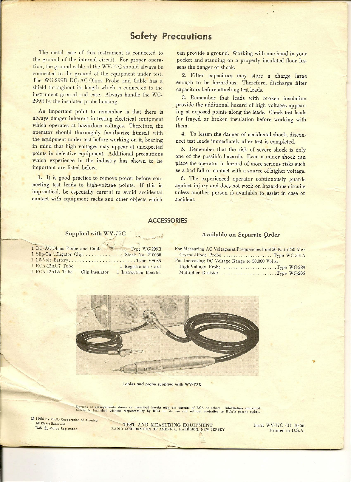
Cables and probe supplied with WV·77C
-:::;...~
Available on Separate 9rder
For Measuring AC Voltages at Frequencies from 50 Kc t0250 Me:
Crystal-Diode Probe Type WC.30IA
For Increasing DC Voltage Range to 50,000 Volts:
High-Voltage Probe ... . Type WG-289
NIultiplier Resistor .. . Type WG·206
..
Devices or arrangem~nt. ~ho""n or tle~cribed herein may ""C patenl~ of
her~ini.furni!hed withon' responsibility by
©
1956 by Rgdio Corporglion of Americg
All Rights Reserved
TMK ®, Mgrcg Regi.lrodg
RCA
RCA
for it~ use lint.! without prejutlice to
TEST AND MEASURING EQUIPMENT
RADIO CORPOHATION OF AMERICA, HARBISON, NEW J£H.SEY
or I)ther~. Information co[]tail]~d
,
RCA'&
patent
r;~"I~.
Inst'- WV-77C
Printed in U.S.A.
(l)
10-56
Page 3
CONTENTS
Safety Precautions _ .
General Desci·jptlon ..
Functions of Controls and Terminals ...
Specifications .. .
Operation and Applications . ..
Accessories . .. ..
Special Applications ..
11aintenance .. . ..
Schema tie Diagram
Replacement Parts List
Page
2
4
4
5
5
8
8
9
10
11
~
Q
'"
U
0
~ +3
~
~
~
'"
I
a
§
z
~
~
-
-'
w
>
W
-'
W
U
Z
W
0:
W
~
W
0:
-'
'"
w
<D
U
w
a
~
~
<D
a
+4
+2
0.1
-
.
0
MILl1WATTS IN 600-0HM RESISTIVE LOAD AT 1000 CPS
!
10 100
,- ,-
10'
-~
,
/
-"
6 7 8
\
.......
:-_.
•
g
10
, ,
,
92CS·7130
6 7 6
g
100
0
,
+1
1/
,
,
,
:
,
,
,
-I
0.1
D
, ,
4
A.C. VOLTS(RMS) MEASURED
,
,
,
,
,
,
,
,
,
,
!>
£,
7:8
g
I
(.0
0.775
, ,
ACROSS 600-0HM RESISTIVE LOAD AT 1000 CPS
,
.
Note: For loads other than 600 ohms, sec
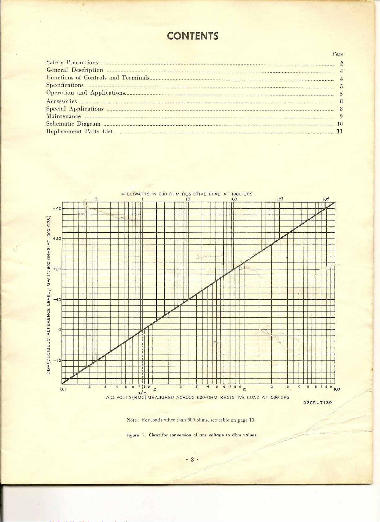
Figure 1. Chart for conversion of rms voltage to dbm values.
lable
on page 10
·3'
Page 4
General Description
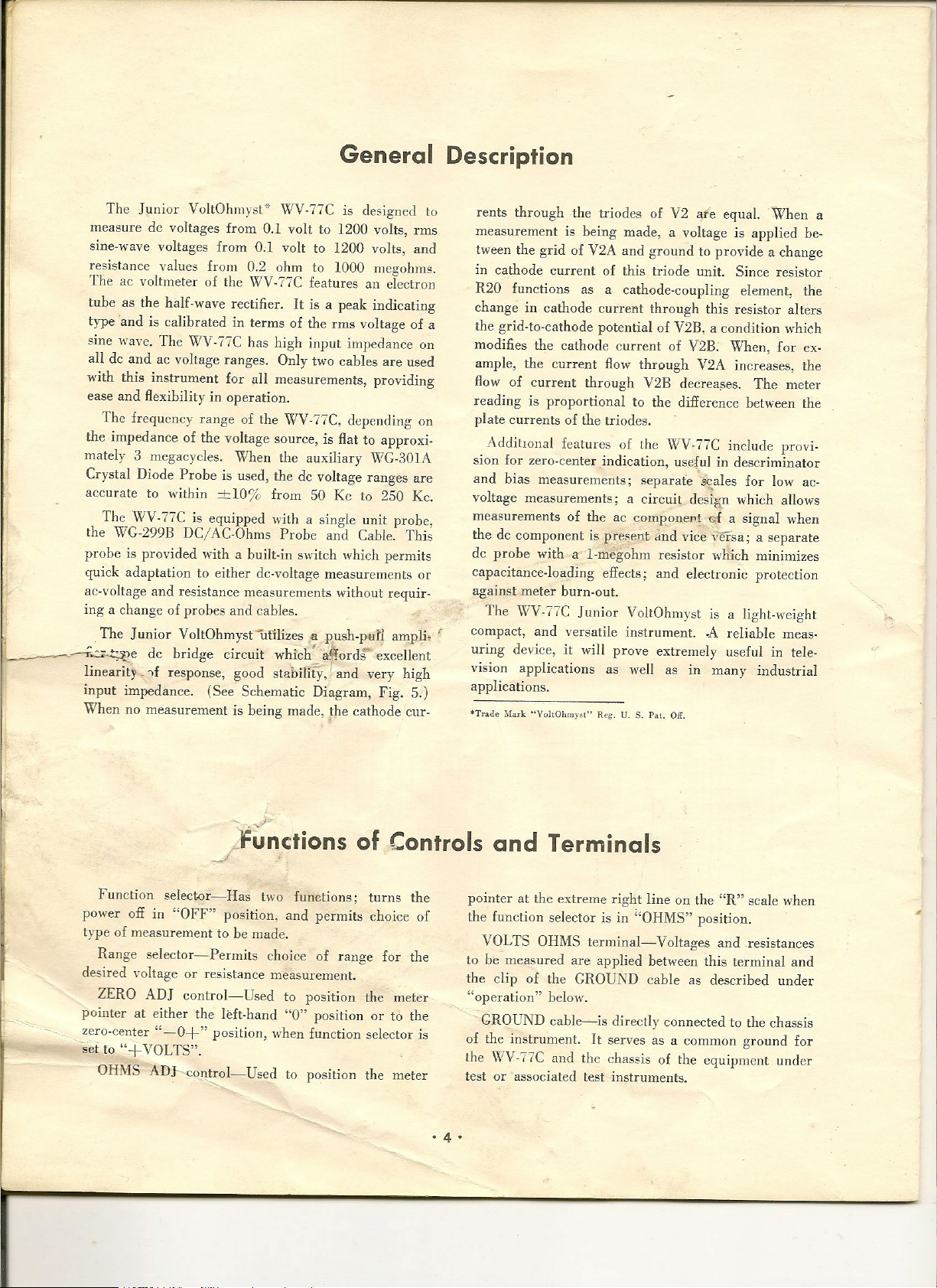
The Junior VoltOhmyst-* WV-77C is designed to
measure de voltages from 0.1 volt to 1200 volts, rms
sine-wave voltages from 0.1 volt to 1200 volts, and
resistance values from 0.2 ohm to 1000 megohms.
The ae voltmeter of the
~rV-77C
features an electron
tube as the half·wave rectifier. It is a peak indicating
type -and is calibrated in terms of the rms voltage of a
sine wave. The V.rV-77C has high input impedance on
all de and ae voltage ranges. Only two cables are used
with this instrument for all measurements, providing
ease and flexibility in operation.
The frequency range of the WV-77C, depending on
the impedance of the voltage source, is flat to approxi-
mately 3 megacycles. When the auxiliary \VG-301A
Crystal Diode Probe is used, the dc voltage ranges are
accurate to within ±10% from 50 Kc to 250 Kc.
The WV-77C is equipped with a single unit probe,
the WG·299B DC/ AC-Ohms Probe and Cable_ This
probe is provided with a built-in switch which permits
quick adaptation to either dc-voltage measurements or
ac-voltage and resistance measurements without requir-
ing a change of probes and cables_
The Junior VoltOhmyst-ufilizes
IJ
~~e de bridge circuit which _ arordr" excellent
lineariij-_.f response, good stability, -and very high
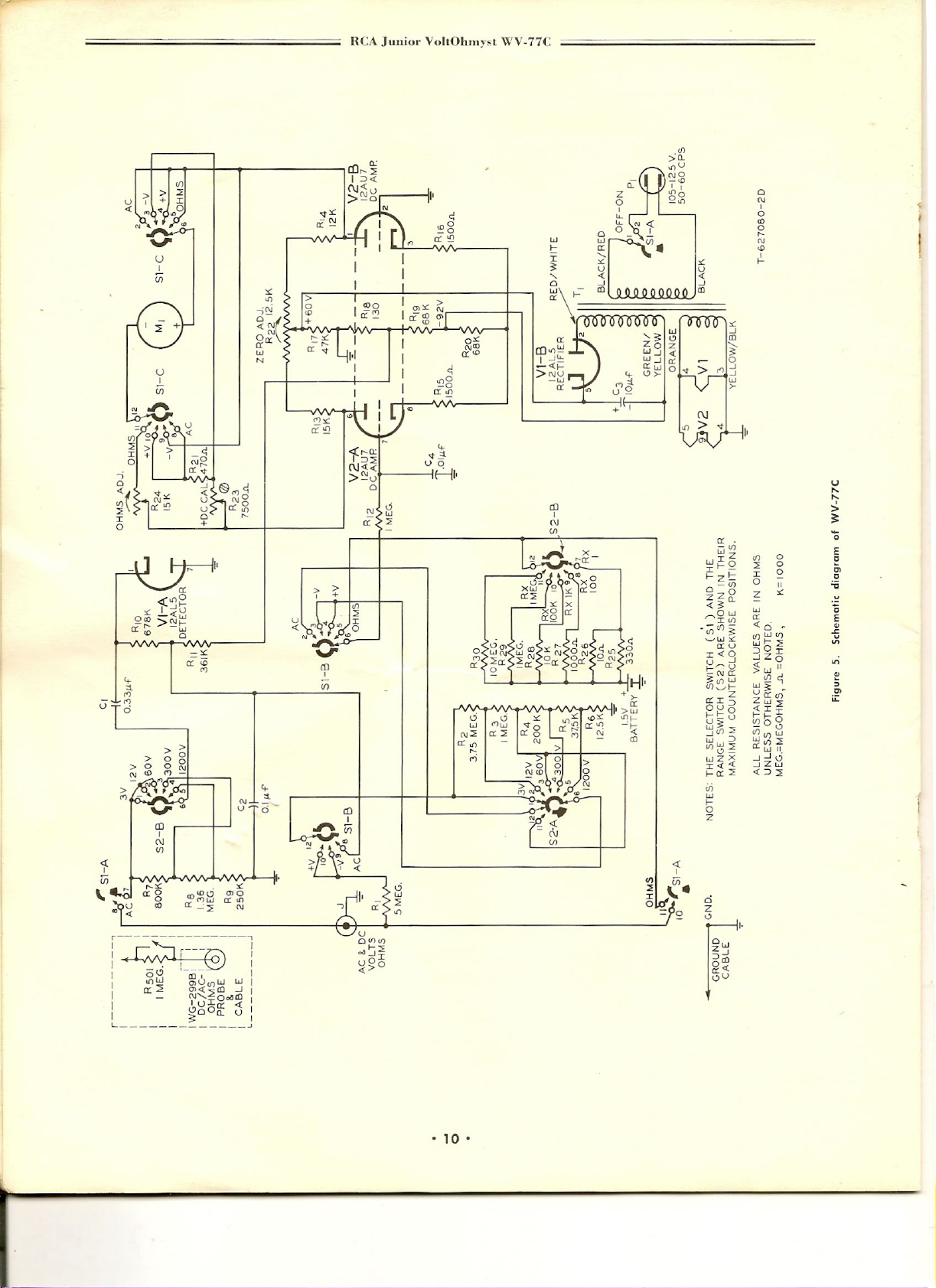
input impedance. (See Schematic Diagram, Fig. 5.)
When no measurement is being made, the cathode cur-
:8
p,ush-put{ ampli.
.
"
rents through the triodes of V2 are equaL When a
measurement is being rnade~ a voltage is applied be-
tween the grid of V2A and ground to provide a change
in cathode current of this triode unit_ Since resistor
R20 functions as a cathode-coupling element, the
change in cathode current through this resistor alters
the grid-to-cathode potential of V2B, a condition which
modifies the cathode current of V2B. When, for ex-
ample, the current flow through V2A increases, the
flow of current through V2B decrea.ses. The meter
reading is proportional to the difference between the
plate currents of the triodes.
AdditlOnal features of the \VV-77C include provi-
sion for zero-center indication, useful in descriminator
and bias measurements; separate 'scales for low ac.
voltage measurements; a circuit desig,n which allows
measurements of the ac component
the de component is pre~ent dnd vice ,~ersa; a separate
dc probe with a I-megohm resistor which minimizes
capacitance-loading effects; and electronic protection
against meter burn-out.
The \VV-77C Junior VoltOhmyst is a light-weight
compact, and versatile instrument. -A reliable meas-
r
uring device, it will prove extremely useful in tele-
vision applications as well as in many industrial
applications.
*Trade !\tark "VoItOlunysl" Reg. U. S. Pal. Off.
,
~-...f
a signal when
--
.../~
,LFunctions
Function selector~Has two functions; turns the
power off in "OFF" position, and permits choice of
type of measurement to be made.
Range selector-Permits choice of range for the
desired voltage or resistance measurement.
ZERO ADJ control-Used to position the meter
pointer at either the left-hand "0" position or to the
zero·center
set to
OHMS ADJ--control-Used to position the meter
"-0+"
"+VOLTS".
position, when function selector is
of Controls and Terminals
pointer at the extreme right line on the "R" scale when
the function selector is in "OHMS" position.
VOLTS OHMS terminal-Voltages and _resistances
to be measured are applied between this terminal and
the clip of the GROUND cable as described under
"operation" below.
GROUND cable--is directly connected to the chassis
of the instrument. It serves as a common ground for
the
~rV-77C
test or associated test instruments .
and the chassis of the equipment under
• 4 •
Page 5
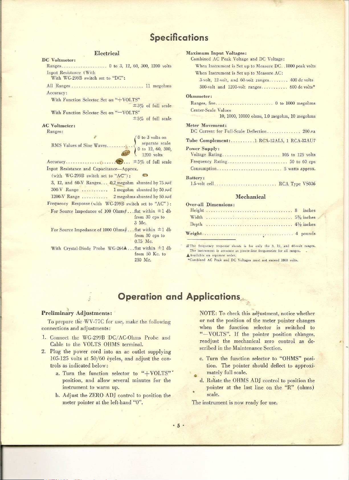
Specifications
Electrical
DC Voltmeter:
Ranges. 0 to 3, 12, 60, 300, 1200 volts
Input Resistance (With
With WG·299B switch set to "DC":
All Ranges.
Accuracy:
With Function Selector. Set on "+VOLTS"
With Function Selector Sct on 'I-VOLTS"
AC Voltmeter:
Ranges:
RMS Values of Sine Waves.
Accuracy. . . . . . . . .
Input Resistance and Capacitance-Ap.prox.
(with WG-299B switch set to "AC") : 0
3, 12, and 60-V Ranges .. " O,,2~ohm shunted by 75
3aO-V
Range
1200-V Range 2 megohms shunted by 50
Frequency Response (with WG-299B switch set to "AC" ) :
For Source Impedance of 100 Ohrrts#. . flat within±1 db
For Source Impedance of 1000 Ohms# ... flat within±1 db
With Crystal-Diode Probe WG-2M.&.... flat within±1 db
,
..... ().. . separate scale
~ 0to12, 60, 300,
tAJP 1200
-e. ..
1
megohm shunted
11 megohms
±3%of
±5%of
{
±
from 30 cps to
3 Me,
from 30 cps to
0.75 Me.
from 50 Kc. to
250 Me.
full scale
full scale
0to3
volts on
volts
5% of full scale
by 50
µµf
µµ£
µµ£
Maximum Input Voltages:
Combined AC Peak Voltage and DC Voltage:
When Instrument is Set up to Measure DC .. 1800 peak volts
When Instrument is Set up to Measure AC:
3-volt. 12-volt, and 60-volt ranges. 400 de volts
300-volt and 1200-volt ranges. 600 de volts·
Ohmmeter:
Ranges, five. 0 to 1000 megohms
Center-Scale Values
10, 1000, 10000 ohms, 1.0 megohm, 10 megohms
Meter Movement:
DC Current for Full·Scale Deflection.
Tube CompleInent:.
Power Supply:
Voltage Rating.
Frequency Rating.
Consumption.
Battery:
1.5-volt cell. RCA Type VS036
. . _ .1 R<ll\-12ALS, 1 RCA-12AU7
105 to 125 volts
5 watts approx.
200 µa
50 to 60 cps
Mechanical
Over-all
Weight.
#The frequency response shown is for only the .~. 12. and 60-volt range~.
AAvailable on separate order.
*Combined AC Peak aud DC Voltages must not exceed 1800 volts.
Dimensions:
I'leight
Width
Depth
The in~tnllnent is accurateatpnwer.line frequencies for all ranges.
8 inches
5% inches
4% inches
4 pounds
Operation and Applications .......
Preliminiry Adjustments:
To prepare tlie ·\VV-77C
connections and adj ustrnents:
1. Connect the WG-299BDC/ AC-Ohms Probe and
Cable to the VOLTS OHMS terminal.
2. Plug the power cord into an ac outlet supplying
105-125 volts at 50/60 cycles, and adjust the con·
troIs as indicated below:
a. Turn the function selector to
position, and allow several minutes for the
instrument to warm up.
b_ Adjust the ZERO ADJ control to position the
meter pointer at the left-hand "0".
for
use~make the following
"+
VOLTS" .
• 5 •
<
NOTE: To check this adjustment, notice whether
or not the position of the meter pointer changes
when the function selector is switched to
"- VOLTS".
If
the pointer position changes,
readjust the mechanical zero control as de-
scribed in the Maintenance Section.
c. Turn the function selector to "OHMS" posi-
tion. The pointer should deflect to approxi.
ma.tely full scale.
•
d. Rotate the OHMS ADJ control to position the
pointer at the last line on the "R" (ohms)
•
scale.
The instrument is now ready for use.
Page 6
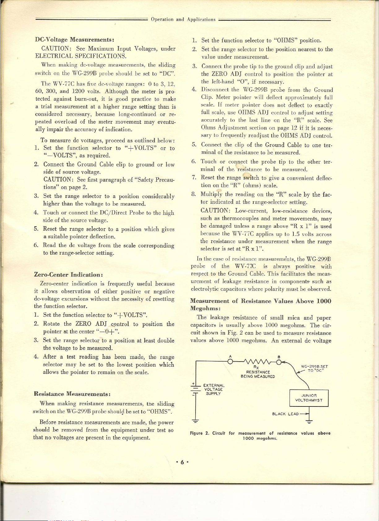
r-
...
Operation and Applications
DC·Voltage Measurements:
CAUTION: See Maximum Input Voltages, under
ELECTRICAL SPECIFICATIONS,
When making dc-voltage measurements, the sliding
switch on the WG-299B probe should be set to "DC".
The WV-77C has five dc-voltage ranges: 0 to 3, 12,
60, 300, and 1200 volts. Although the meter is pro-
tected against burn-out,
a trial measurement at a higher range setting than is
considered necessary, because long-continued or re-
peated overload of the meter movement may eventu-
ally impair the accuracy of indication.
To measure de voltages, proceed as outlined below:
1.
Set the function selector to
"- VOLTS",
2. Connect the Ground Cable clip to ground or low
side of source voltage.
CAUTION: See first paragraph of "Safety Precau·
tions" on page
3. Set the range selector to a position considerably
higher than the voltage to be measured.
4_ Touch or connect the DC/Direct Probe to the high
side of the source voltage.
5. Reset the range selector to a position which gives
a suitable pointer deflection.
6. Read the dc voltage from the scale corresponding
to the range-selector setting.
Zero~Center Indication:
Zero-center indication is frequently useful because
it allows observation of either positive or negative
dc-voltage excursions without the necessity of resetting
the function selector.
1.
Set the function selector to"+VOLTS".
2. Rotate the ZERO AD] Q9ntrol to position the
pointer at the center
3. Set the range selector to a position at least double
the voltage to be measured.
4. After a test reading has been made, the range
selector may be set to the lowest position which
allows the pointer to remain on the scale.
Resistance Measurements:
When making resistance measurements, the sliding
switch on the WG·299B probe shoul~ be set to "OHMS".
Before resistance measurements are made, the power
should be removed from the equipment under test so
that no voltages are present in the equipment.
as
2.
it
required.
H_O+".
is good practice to make
"+
VOLTS" or to
;:;;;====================
1. Set the function selector to "OHMS" position.
2_ Set the range selector to the position nearest to the
value under measurement.
3. Connect the probe tip to the ground clip and adjust
the ZERO ADJ control to position the pointer at
the left-hand "0", if necessary.
4. Disconnect the WG-299B probe from the Ground
Clip. Meter pointer will deflect approximately full
scale.
If
meter pointer does not deAect to exactly
full scale, use
accurately to the last line on the "R" scale. See
Ohms Adjustment section on page 12 if it is neces-
sary to frequently readjust the
5. Connect the clip of the Ground Cable to one ter-
minal of the resistance to be measured.
6. Touch or connect the probe tip to the other ter-
minal of the, 'resIstance to be measured.
7. Reset the range switch to give a convenient deflec-
tion on the "R" (ohms) scale.
8. Multiply the reading on the "R" scale
tor indicated at the range-selector setting.
CAUTION: Low-current, low-resistance devices,
such as thermocouples and meter movements, may
be damaged unless a range above "R xl" is used
because the \VV-77C applies up to 1.5 volts across
the resistance under measurement when the range
selector is set at "R xl".
In the case of resistance measurements, the WG-299B
probe of the WV-77C is always positive with
respect to the Ground Cable. This facilitates the meas-
urement of leakage resistance in components- such as
electrolytic capacitors where polarity must be observed.
Measurement of Resistance Values Above 1000
Megohms:
The leakage resistance of small mica and paper
capacitors is usually above
cuit shown in Fig. 2 can be used to measure resistance
values above
+
EXTERNAL
VOLTAGE
SUPPLY
OHMS
e
1000
A
ADJ control to adjust setting
OHMS
1000
megohms. The cir~
megohms. An external de voltage
•
RX
RESISTANCE
BEING MEASURED
BLACK LEAO
ADJ controL
by
the fac~
WG-2998 SET
TO"OC"
I
Figure 2. Circuit for measurement of resistance values above
1000 megohms .
• 6 •
Page 7
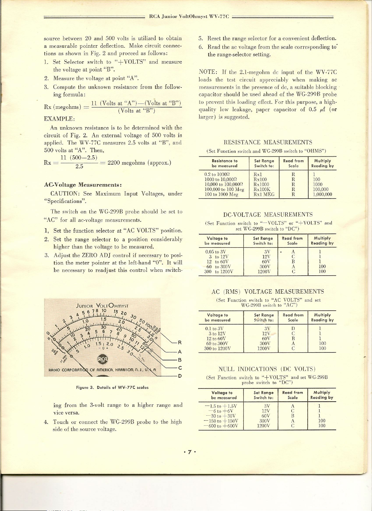
neA
Jilniol' VohOhmyst
WV-77C
source between 20 and 500 volts is utilized to obtain
a measurable pointer deflection. Make circuit connec-
tions as sho'wn in Fig. 2 and proceed as follows:
1.
Set Selector s'witch to
"+
VOLTS" and measure
the voltage at point "B".
2. Measure the voltage at point "A".
3. Compute the unknown resistance from the follow-
ing formula:
(Volts at "A")-(Volts at "B")
Rx (megohms) =
11
(Volts at "B")
EXAMPLE:
An unknown resistance is to be determined with the
circuit of Fig. 2. An external voltage of 500 volts is
applied. The ViV·77C measures 2.5 volts at "B", and
500 volts at "A". Then,
11
Rx
(500-2.5)
= ~_ =
2200 megohms (approx,)
AC-Voltage Measurements:
CAUTION: See Maximum Input Voltages, under
"Specifications".
The switch on the
·WG·299B
probe should be set to
"AC" for all ac-voltage measurements.
I, Set the function selector at "AC VOLTS" position.
2. Set the range selector to a position considerably
higher than the voltage to be measured.
3, Adjust the ZERO ADJ control if necessary to posi.
tion the meter pointer at the left-hand "0".
It
will
be necessary to readj ust this control when switch-
5. Reset the range selector for a convenient deflection.
6. Read the ac voltage from the scale corresponding to'
the range-selector setting.
NOTE:
Jj
the 2.1-111egohm de input of the WV-77C
loads the test circuit appreciably when making ac
measurements in the presence of dc, a suitable blocking
capacitor should be used ahead of the WG-299B probe
to prevent this loading effect. For this purpose, a high-
quality
10\,,'
leakage, paper capacitor of 0.5 ,uf (or
larger) is suggested.
RESISTANCE MEASUREMENTS
(Set
Function switch and
Resistance to Set Range Read from Multiply
be measured Switch to: Scale Reading by
0.2 to 1000~ Rx1
1000 to 10.000n
10,000to100,000n
100,00010100 l\Jeg RxlOOK R 100,000
100 to 1000 Meg
WG-299B
Rxl00 R 100
RxlOOO
Rxl MEG R 1.000,000
switch to
R 1
R 1000
"OHJ\lS")
DC-VOLTAGE MEASUREMENTS
(Set Funclion switch to "-YOLTS" or "+Y01..'I'S" and
Vollage to Set Range
be measured Switch to: Scale
0.05 to 3V 3Y
3 to 12V
12to60V 60V B 1
60to300V SOOV
300to1200Y
set WG·299B switchto"DC")
Read from
12V
1200V
A
A
Multiply
Reading by
1
C
C
1
100
100
JuniOR VOUOHffiVST
5 ,,78 10 15,
.~o
RRDIO CORPORATI
Figure 3. Details of WV-77C scales
567
1.5
30
ing from the 3-volt range to a higher range and
vice versa.
4. Touch or connect the WG-299B probe to the high
side of the source voltage.
·7'
AC (RMS) VOLTAGE MEASUREMENTS
(Set Function switch to "AC VOLTS" and set
Voltage 10 Set Range Read from
be measured S·~-.Iitchto: Scale
0.1 to 3V 3V
3 to 12V 12V
12 to 60V
60to300V 300V
300 to 1200V
WG·299B
switch
60V
1200V
to "AC")
0
C
B
A
C
NULL INDICATIONS (DC VOLTS)
(Set
Function switch to
Voltage to
be measured
-1.5 to +1.5V 3V
-6 to +6V
-30to+30V 60V B 1
-150to +lSOV 300V
-600 to +600V
probe
"+ VOLTS"
switch to
Sel Range Read from Multiply
Switch to: Scale
12V
1200V
"DC")
and
A
C
A
C
set
WG·299B
Multiply
Reading by
1
1
1
100
100
Reading by
1
1
100
100
Page 8
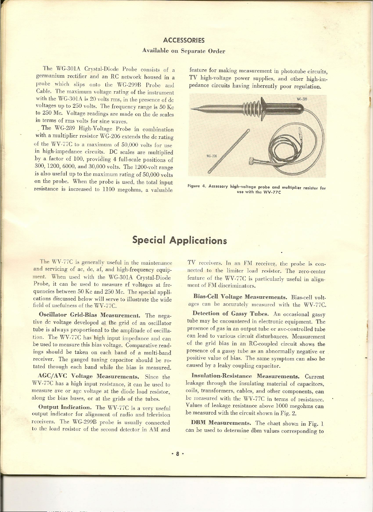
ACCESSORIES
Availahle on Separate Order
The WG-301A Crystal-Diode Probe consists of a
germanium rectifier and an RC network housed in a
probe which slips onto the \VG-299B Probe and
Cable. The maximum voltage rating of the instrument
with the WG-301A is 20 volts nns, in the presence of de
voltages up to
to
250
Me. Voltage readings are made on the de scales
in terms of TIns volts for sine waves.
_ The WG-289 High-Voltage Probe in combination
with a multiplier resistor WG-206 extends the de rating
of the
\'\iV-fie
in high-impedance circuits. DC scales are multiplied
by a factor of 100, providing 4 full-scale positions of
300, 1200, 6000, and 30,000 volts. The 1200-volt range
is also useful up to the maximum rating of 50,000 volts
on the probe. When the probe is used, the total input
resistance is increased to 1100 megohms, a valuable
250
volts. The frequency range is 50 Kc
to a maximum of 50,000 volLs for usc
Special Applications
feature for making measurement in photo tube circuits,
TV high-voltage power supplies, and olher high-im-
pedance circuits having inherently poor regulation.
Figure 4. Accessory high-voltage probe and multiplier resistor for
use with the WV-77C
The \'\lV-r7C is generally usefulinthe maintenance
and servicing of ac, dc, af, and high-frequency equip-
ment. ""hen used with the '''G-301A Crystal-Diode
Probe, it can he used to measure
quencies between 50 Kc and 250 Mc. The special appli-
cations discussed below will serve to illustrate the wide
field of usefulnessofthe WV-77C.
Oscillator Grid-Bias l\ieasurelnent.
tive de voltage developed at the grid of an oscillator
tube is always proportional to the amplitude of oscilla-
tion. The WV-77C has high input impedance and can
be used to measure this bias voltage_ Comparative read-
ings should be taken on each band of a multi-band
receiver. The ganged tuning capacitor should be ro-
tated through each band while the bias is measured.
AGe/AVe Voltage Mca8urements.
\VV·77C has a high input resistance, it can be used
measure avc or agc voltage at the diode load resistor,
along the bias buses, or at the grids of the tubes.
Output Indication.
output indicator for alignment of radio and television
receivers. The \'\iC-299B probe is usually connected
to the load resistor of the second detector in AM and
The WV-77C is a very useful
rf
voltages at fre-
The nega-
Since the
TV receivers. In an FM receiver, the probe is con-
nected to the limiter load resistor. The zero-center
feature of the WV-77C is particularly useful in align-
ment of FM discriminators.
Bias-Cell Voltage Measurements.
ages can be accurately measured with the WV -77C.
Detection of Gassy Tubes.
tube may be encountered in electronic equipment. The
presence of gas in an output tube or avc-controlled tube
can lead to various circuit disturbances. Measurement
of the grid bias in an RC-coupled circuit shows the
presence of a gassy tube as an abnormally negative or
positive value of bias. The same symptom can also be
caused by a leaky coupling capacitor.
Insulation-Resistance Measurements.
to
leakage through the insulating material of capacitors,
coils, transformers, cables, and other components, can
be measured with the WV-77C in terms of resistance.
Values of leakage resistance above 1000 megohms can
be measured with the circuit shown in Fig. 2_
DBM Measurements.
can be used to determine dbm values corresponding to
The chart shown in Fig. 1
Bias-cell volt-
An occasional gassy
Current
·8·
Page 9
;;:=~=================;;;;;=====;;;;
i'dainLenance
I
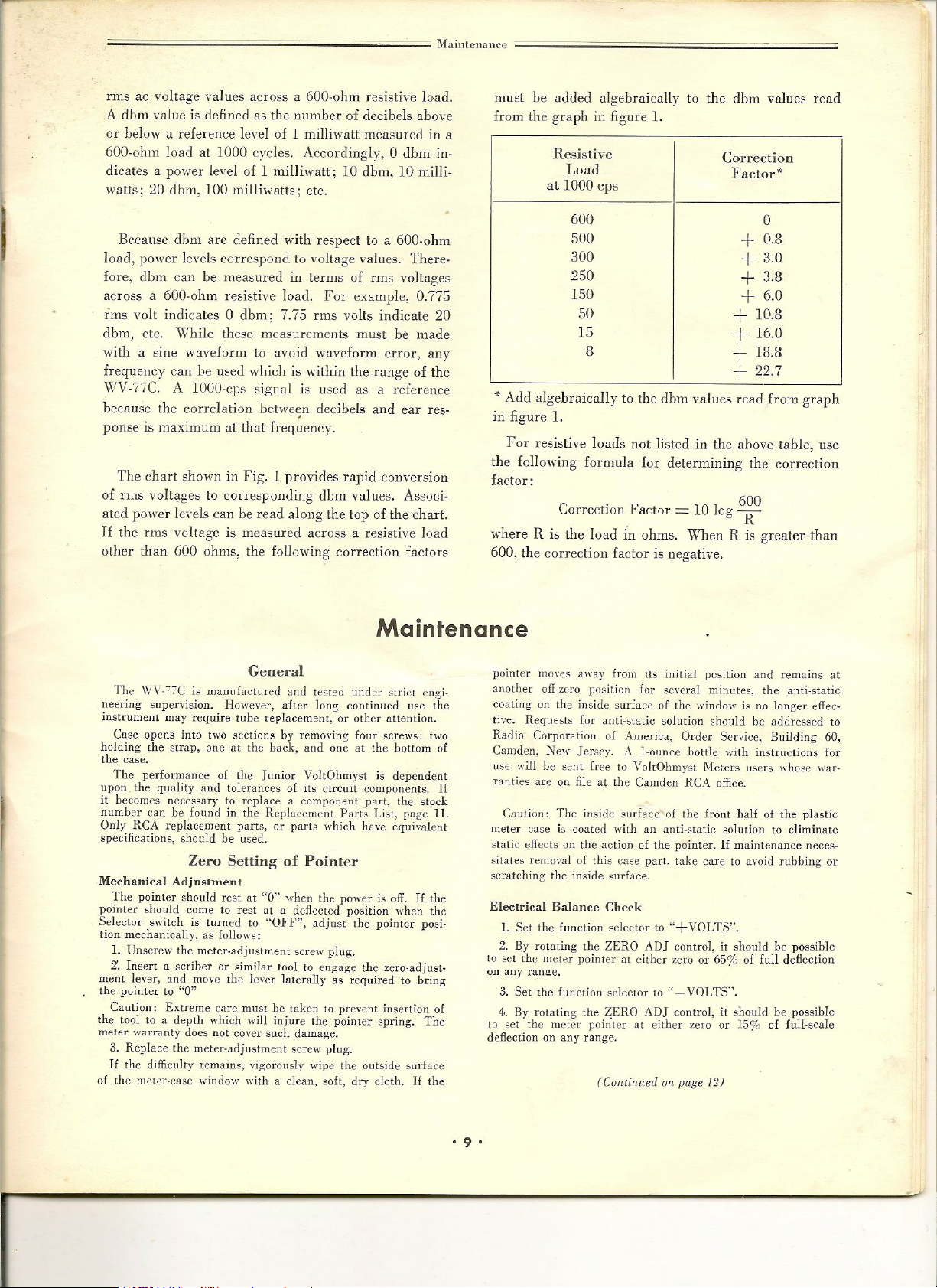
rms ae voltage values across a 600-ohm resistive load.
A dbm value is defined as the number of decibels above
or below a reference level of 1 milliwatt measured in a
600-ohm loadaL1000 cycles. Accordingly, 0 dbm in-
dicates a power level of 1 milliwatt; 10 dbm, 10 milli-
watts;
20
dbm, 100 milliwatts; etc.
Because dbm are defined ,\lith respect to a 600-ohm
load, power levels correspond to voltage values. There-
fore, dbm can be measured in terms of rms voltages
across a 600-ohm resistive load. For example, 0.775
rms volt indicates 0 dbm; 7.75
dbm, etc. While these measurements must be made
with a sine waveform to avoid waveform error, any
rms
volts indicate 20
frequency can be used ·which is within the range of the
\XlV-77C. A lOOO-cps signal is used as a reference
because the correlation bet,veen decibels and ear res-
ponse is maximum at that freq~ency.
The chart sholl,'n in Fig. 1 provides rapid conversion
of
n,lS
volt~ges to corresponding dbm values. Associ-
ated power levels can be read along the top of the chart.
If
the rms voltage is measured across a resistive load
other than 600 ohms, the following correction factors
must be added algebraically to the dbm values read
from the graph in figure
Resistive
Load
1.
Correction
Factor"><
at 1000 cps
600
500
300
250
150
50
15
8
0
+ 0.8
+ 3.0
+ 3.8
+ 6_0
+ 10_8
+ 16_0
+ 18.8
+ 22_7
* Add algebraically to the dbm values read from graph
in figure
For resistive loads not listed in the ahove table, use
the following formula for determining the correction
factor:
where R is the load in ohms. When R is greater than
600, the correction factor is negative.
1.
Correction Factor
=
10 log 6~O
Maintenance
General
The WV·i7C is manufactured and tested under strict engi·
neering supervision. l-Iowever, after long continued use the
instrument may require tube replacement, or other attention.
Case opens into two sections by removing fOllr screws: two
holding the strap, one at the back, and one at the bottom of
the case.
The performance of the Junior VoltOhmyst is dependent
upon the quality and tolerances of its circuit components.
it becomes necessary to replaceacomponent part, the stock
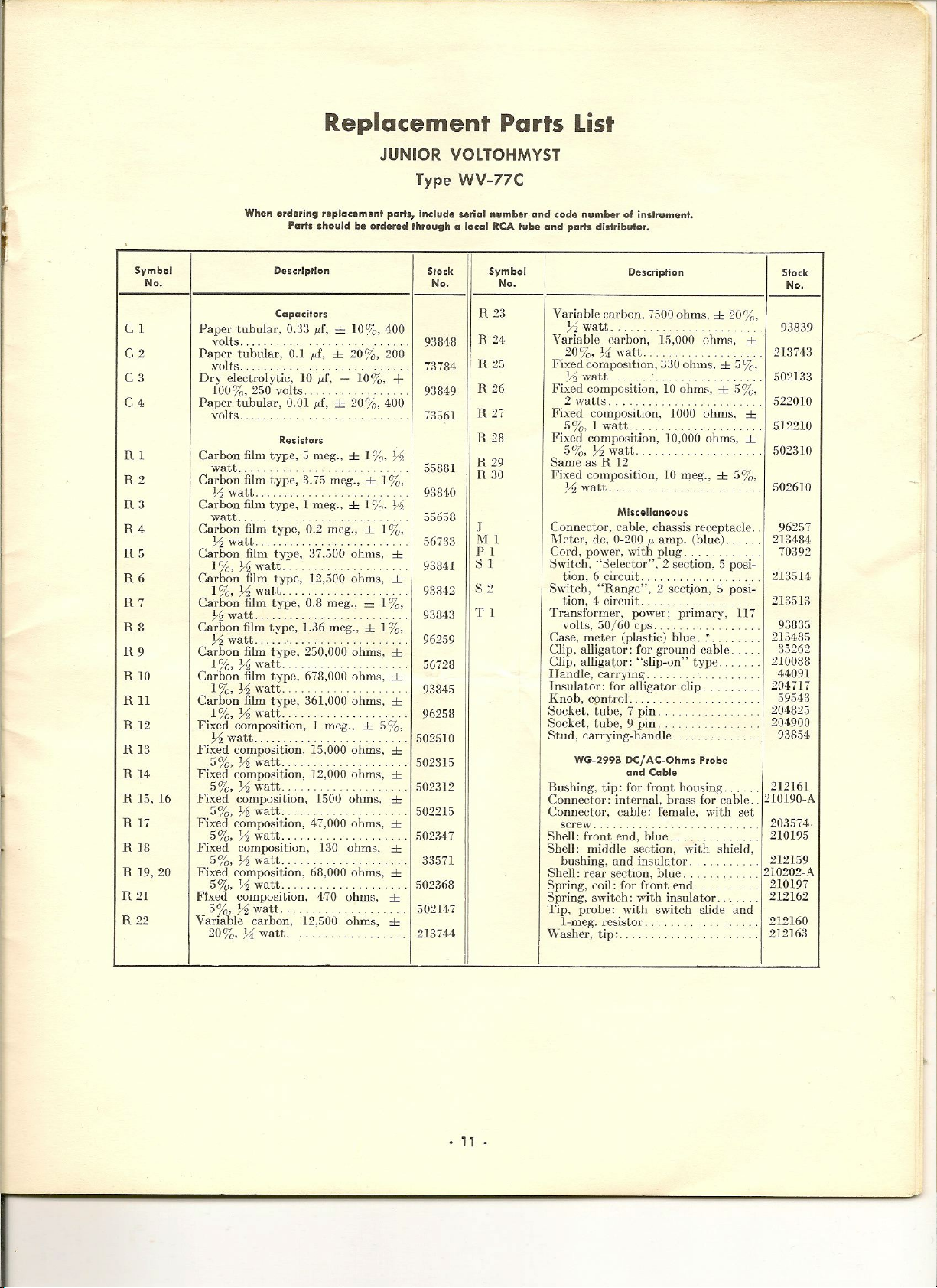
number can be found in the Replaeemcnt Parts List, page
Only RCA replacement parts, or parts which have equivalent
specifications, shouldbeused.
Zero Setting of Pointer
Mechanical Adjustment
The pointer should rest at "0" when the power is off.Ifthe
pointer should come to rest at a deflected position when the
Selector switch is turned to "OFF", adjust the pointer posi·
tion mechanically, as follows:
1.
Unscrew the meter·adjustment screw plug.
Z.
Insert a scriber or similar tool to engage the zero·adjust-
ment lever, and move the lever laterally as required to bring
the pointer to "0"
Caution: Extreme care must be taken to prevent insertion of
the tool to a depth which
meter warranty does not cover such damage.
3. Replace the meter·adjustment screw plug.
If
the difficulty remains, vigorously wipe the outside surface
of the meter·case window with a clean, soft, dry cloth.1£the
will
injure the pointer spring. The
11.
pointer moves away from its initial pGsition and remains at
another off·zero position for several minutes, the anti·static
coating on the inside surface of the window is no longer eircc-
live. Requests for anti·static solution should be addressed to
Radio Corporation of America, Order Service, Building 60,
Camden, New Jersey.
lise will be sent free to VoltOhmyst Meters users whose war·
If
ranties are on file at the Camden RCA office.
Caution: The inside surface of the front half of the plastic
meter case is coated with an anti·static solution to eliminate
static effects on the action of the pointer.Ifmaintenance neces·
sitates remo\'al of this Case part, take care to avoid rubbing or
scratching the inside surface,
Electrical Balance Check
1.
Set the function selector to "+VOLTS".
2. By rotating the ZERO ADJ control, it should be possible
to set the meIer pointer at either zero or 65% of full deflection
on any ran!.!e.
3. Set the function selector to "- VOLTS".
4. By rotating the Z;ERO ADJ control,itshould be possible
to set the meIer pointer at either zero or 150/0 of full·scale
deflection on any range.
A
I·ounce bottle with instructions for
(Contillued on page 12)
• 9 •
Page 10
[leA
Juuior VoltOlllUYlill
WV·77C
>~r
N "'-"
-
'"
+
I
y.
U
,
Vi
U I
<~.
d
U
,
Vi
.,..
~
-~
N,
~.
v
NO
~~~3
v '" '"
o '
•
~['
<",0
~>-
Q~
5~~
a: ~ -~
~
~
~
-,,"~
U
-r
ci
>
~~~
,
"
~-J
:<Iv '"
• <
f-~~~~_@--'
,
I -~ ,---
1
I
I -
I
[
L -'
>
0 0 N
CD
-"
,
N
<n
i~-
-
~w
a:; ~
---./VV\
-~
~ii5
> >
0
g
0;)1013 $0
a:!")wa::.n
,
,
~uV)w
01«::E0l...J I
~~J:~o/!~ I
'-'o0a.. u I
;;
~
....:~ N
INn_
VIc)
~
W I
~
'"
-i~
~~(
g~
W
N
,
,
I
,
>
g
•
> >
,
T
~g
1
~-
-,
.
~
~),:~'?i6
~
cO
,
I, _
"
o
N
,
o
~
o
,
N
'"
~
>
~l'--h
N
\A)L
u
~
~
cO
,
N
<n
~
=y,?
~
~
wu1
IZ
w
rl-Q
I--
Z
-'"
gzo
<~~
~Ow
-;nVl3
"'"
~w~
a:v
I<O
~---d
-Na:
~If)W
~>-
","
ou=>
>->-0
u
v-
~~::!:
w =>
",w,
,,-
wz
r«
>-
a:,
,,;
w
>-
°
Z
a
Z
"
0
<II
,
0
0
I
1::
Z
x
-
°
"
~
~
w
~
<6
",w",
w>-,
=>°I
~20
~wn
w\[!
cl
v· -
z"''''
<t:~~
>->-"
<:208
"'",w
w", ,
a:
W 11
...J...Jo,j
~Zw
<=>,
,;.
'0
"
'0
.,
1;
~
oJ;
.,;
"'
E
•
m
•
E
'"
•
•
;
• 10 •
Page 11
Replacement Parts List
JUNIOR VOlTOHMYST
Type WV-77C
When ordering replacement parts, include seriol number and code numbe, of Instrumenl.
Part. should b. ordered through a local RCAtub. and porf.
distributor.
Symbol
No,
C I
C2
C3
C4
Rl
R2
R3
R4
R5
R6
R7
R8
R9
RIO
Rll
R
12
R
13
R
14
R 15, 16
R17
R
18
R
19, 20
R 21
R 22
Description
Capacitors
Paper tubular, 0.33
volts. 93848
Paper tubular, 0.1
.volts. 73784
Dry electrolytic, 10
100%,250
Papef tubular, 0.01
volts.. 73561
Carbon film type,S meg.,±1
watt.. .
Carbon film type, 3.75 meg.,±1
Yz
watt..
Carbon film type, 1 meg.,±1
watt.
Carbon film type, 0.2 meg.,±1%,
Yz
watt.
Carbon film type, 37,500
1
%,
Yz
Carbon
Carbon
Carbon film type,
Carbon film type,
Carbon film type,
Carbon film type, 361,000 ohms,
Fixed composition,1meg.,
Fixed composition,
Fixed composition,
Fixed composition,
Fixed composition,
Fixed composition,
Fixed composition,
Fixed composition,
5%,
Variable carbon,
20%,
watt.. .
film
1 %,Yzwatt. .
film
Yz
watt.
Yz
watt. 96259
1%,
Yz
watt. .
1%,
Yz
watt.
1
%,
Yz
watt. .
Yz
watt.
5%,
Yz
watt.
5%,
Yz
watt..
5%,
Yzwatt.
5%,
Yz
watt,. 502347
5%,
Yz
watt. .
5%,
Yz
watt.
Yz
watt.
74
watt. 213744
volts.
Resistors
type,
type,
0.8
1.36
250,000
678,000
12,500
µf,±10%, 400
µf,±20%, 200
µf, -
10%,
µf,
±
20%, 400
%,
%,
ohms,
12,500
ohms,
meg.,±1%,
meg.,±1%,
ohms,
ohms,
±
5%,
15,000
ohms,
12,000
ohms,
1500
ohms,
47,000
ohms,
130
ohms,
68,000
ohms,
470
ohms,
ohms,
+
Yz
%,
Yz
±
±
±
±
±
±
±
±
±
±
±
±
±
Stock
No_
93849
5588]
93840
55658
56733
93841
93842
93843
56728
93845
96258
502510
502315
502312
5022L5
33571
502368
502147
H 23
R 24
R
R 26
It
11
R
R
J
ML
PI
S I
82
T I
Symbol
No.
25
27
28
29
30
Description
Variable carbon,
Yz
watt. ,
Variahle carbon,
20%,
Fixed composition,
Fixed composition,
Fixed composition,
Fixed composition,
Same as
Fixed
Connector, cable, chassis receptacle.
IVleter, dc,
Cord, power, with plug.
Switch, "Selector",2section,5posi~
Switch, "Range",2sectjon,5posi-
Transformer, power; primary,
Case, meter (plastic) blue .. '.
Clip, alligator: for ground cable.
Clip, alligator: "slip-on" type.
Handle, carrying.
Insulator: for alligator clip,
Knob, cpntrol.
Socket, tube,7pin.
Socket, tube,9pin.
Stud, carrying-handle.
Bushing, tip: for fl'Ont housing. 212161
Connector: internal, brass for cable.
Connector, cable: female, ,viLb set
Shell: front end, blue.. .' . 210195
Shell: middle section, with shield,
Shell: rear section, blue
Spring, coil: for front end.
Spring, switch: with insulator.
Tip, probe: with switch slide and
Washer, tip: 212163
}4
Yz
watt.
2'\'atts.
5%, 1
5%,
Yz
R 12
composition,
Yz
watt.
tion,6circuit.
tion,4circuit.
volts,
50/60
WG~299B
screw. 203574·
bushing, and insulator. 212159
I-meg. resistor.
75000hrns,
15,000
watt.
330
o.hms,±5%,
10
ohms,±5%,
watt.
watt.
Miscellaneous
0~200µamp. (blue) ...
10,000
10
cps.
Dcl
AC~Ohms Probe
and Cable
1000
meg.,±5%,
±
ohms,
ohms,
ohms,
20%,
117
±
±
±
Stock
No.
93839
213743
502133
522010
512210
502310
502610
962;;7
213484
70392
21:3514
213513
9:1835
2D48S
;~5262
210088
44091
204717
59543
204825
204900
93854
210190~A
210202-A
210197
212162
212160
• 11 •
Page 12
S.Ifsteps 2 and 4 above cannot be accomplished, the two
triode units of the 12AU7 tuhes are not in close enough bal.
ance for this application and the tube should be replaced.
DC Zero Check
L Set functioll selector to "-VOLTS".
2. Set range selector on "3V".
3. Rotate the ZERO ADJ control until the meter pointer is
at zero.
4. Turn range switch to "1200V".
5.Ifthe meter pointer deviates from zero by more than one
division 011 the 0 to 12 metcr scale, replace thc 12AU7 (see
section on Tu be Replacement).
AC Zero
on "+VOLTS".
the 60V meter scale.
the 12AL5. Thc use of a 12ALS which results ill a meter read-
ing outside of ,his 7-13 volt range
of the instrument but
adjustment of the ZERO ADJ control.
Check
J.
Set the range selector on "3V" and the function selector
2. Rotate ZERO ADJ control until meter reads 10 volts on
3. Turn the function selector to "AC VOLTS".
4.Ifthe meter does not read between 7 and 13 volts, replace
will
will,
however, require more frequent
not impair the accura~y
Calibration
1. Set the range selector to ;'60V" and the function selector
to
"+VOLTS"_
2. Set thc meter pointer to zero by using the ZERO ADJ
controL
3. Set the sliding switch on the probe to "DC".
4. Connect the Ground Cable to the negative terminal alld
the probe tip to the positive terminal of a source of DC
Voltage that has been adjusted to exactly 57 volts.
Note: The accuracy of calibratioll cannot cxceed the accuracy
of the voltage standards which are used.
5. Adjust the ';DC CAL" control (R-23) inside the case for
a meter reading of exactly 57 volts.
6. Remove the leads at the source of voltage.
7. Set the function selector to "-VOLTS".
8. Connect the Ground Cable to the pOSiLi\'e terminal and the
probe tip to the negative tenJlinal of the dc-voltage source
adjusted to exactly 57 volts. The WV-77C should read 57 volts
within ±3%.
9.Ifthe WV-77C cannot be calibrated according to the
foregoing steps the 12A U7 amplifier tube may not be properly
balanced for this application.
Tube Replaceillent
All tubes supplied originally with the WV-77C have been
thoroughly aged by operating them for several hours before
illstallatiOri in the instrument. This preliminary conditioning
of a new tube helps to insure stability and dependable per-
formance.
Before installing a 12AU7, the tube may be aged as follows:
connect the plates together and apply 115 volts dc. Operate
the grids and cathodes with no voltage applied, and operate
the heaters at 6.3 volts. The tube should be operated in this
manner for a minimum of 12 hours before it is installed in
the instrument. The WV·77C then can be recalibrated.
An alternate, and usually satisfactory, aging procedure con-
sists of operating the new tube in the WV-77C for approxi-
mately 36 hours, after which time the instrument may be
recalibrated.
procedure should be followed.
If
be aged for a minimum period of 36 hours by operating it in
the \VV-77C. After this period of time, the instrument may
be recaliurated according to the procedure outlined under "AC
Calibration Check".
If
this procedure is unsatisfactory, the first aging
it becomes necessary to replace the 12AL5, the tube can
Battery Testing and Replacement
Caution: Do not allow exhausted cells to remain inside the
case of the WV-77C. Chemicals from deteriorated cells may
damage the instrument.
The battery should be tested to insure accu racy of resistance
measurements. To test battery, proceed as follows:
L Set .Function selector to "OHl\.lS".
2. Set Range selector to "R x 1" scale.
3. Rotate OH2VIS ADJ control to bring pointer to full scale.
4. Short·circuit the probe tip and ground clip for about
ten seconds.
5. Open the short-circuit and immediately observe the scale
indication. An appreciable deviation from full-scale indication
reveals weak cells which should be replaced.
Ohms Adjustment
In order to obtain exactly full-scale deflection of the meter
when switching the range selector from a low range position
to the R x 1MEC position, it may be necessary to readjust
the OHMS ADJ control. The necessity for this readjustment
can be minimized by checking the bauery and installing a
12AU7 tube with a low value of grid current. Refer to Tube
Replacement section.
RCA Repair Service
RCA maintains a complete repair service for the adjustment,
calibration, and maintenance of RCA t~st equipment.
becomes necessary to service this equipment, the report forms
enclosed in this booklet should be filled out as described.
important that:
1.
Test equipment be packed carefully,
2. A full description of the trouble be included in the report.
3. All probes and cables be included with the instrument.
Attention to these details will help prevent damage in transit
and delay in repairs .
If
It
it
is
. 12 •
Page 13
I
 Loading...