

RCA WSP155 Owner's Manual
WSP155
* Range may vary by environment.
* La portée peut varier selon l’environnement.
* El alcance puede variar según el entorno.
900MHz Wireless Speaker System
Enceintes sans fil de 900 MHz
Sistema Inalámbrico de Bocinas
de 900MHz
Transmits stereo signal
even outside your home!
Émet un signal stéréo même
à l’extérieur de la maison!
¡Transmite señal estereofónica
incluso afuera de su casa!
WSP155_US_IB_REVB.qxd 5/26/05 11:48 AM Page 1
150ft*/45m
150ft*/45m
*
*

Keep your sales receipt to obtain warranty parts and service and for
proof of purchase. Attach it here and record the serial and model
numbers. These numbers are located on the product.
Model No. ____________________________________
Serial No. ____________________________________
Purchase Date: _________________________________
Dealer/Address/Phone: ____________________________
__________________________________________
TABLE OF CONTENTS
Introduction ...........................................................................3
Features ................................................................................3
Care and Maintenance ..............................................................3
Parts.....................................................................................4
Installation.............................................................................5
Operation Notes......................................................................7
Troubleshooting ......................................................................8
Specifications..........................................................................8
Warranty ...............................................................................9
INTRODUCTION
This WSP155 Wireless Speaker system uses the latest 900 MHz RF
technology that enables you to enjoy stereo sound anywhere around
your home—even outside on your deck or patio! Just follow the simple
instructions to connect the transmitter to any audio source (CD, DBS,
VCR, Stereo, Radio or TV) for full stereo sound without the need to run
wires to your speakers. You may place the speakers anywhere within
range (approx. 325 feet) of the transmitter to receive the stereo signal.
FEATURES
• 900 MHz RF technology
• RF technology allows high degree of freedom for speaker placement
• Operating distance up to 150ft*/45m*
• No line-of-sight limitation
• ALC and auto ON/OFF control
• Convenient power, volume and tuning controls located on
the speakers
CARE AND MAINTENANCE
With proper care, your speaker system will provide you with years of
enjoyment. Here are a few guidelines to follow in caring for your system:
• Always use a soft cloth to clean the speakers and transmitter. If
required, you may use a mild detergent and warm water to clean any
dirt or dust from the component surfaces. Never use any product
containing alcohol or other solvents as they may damage the surface.
• Use caution when plugging the power transformers in an AC outlet
to avoid the risk of electric shock.
• Never expose the speakers or transmitter to rain or moisture as this
may cause damage. If the speakers are used outside on a deck or
patio, make sure you take them indoors in the event of a rainstorm
to prevent possible damage.
• Do not operate or store the system in extreme temperatures below
32°F (0°C) and above 122°F (50°C).
*Range may vary by environment.
WSP155_US_IB_REVB.qxd 5/26/05 11:48 AM Page 2
54
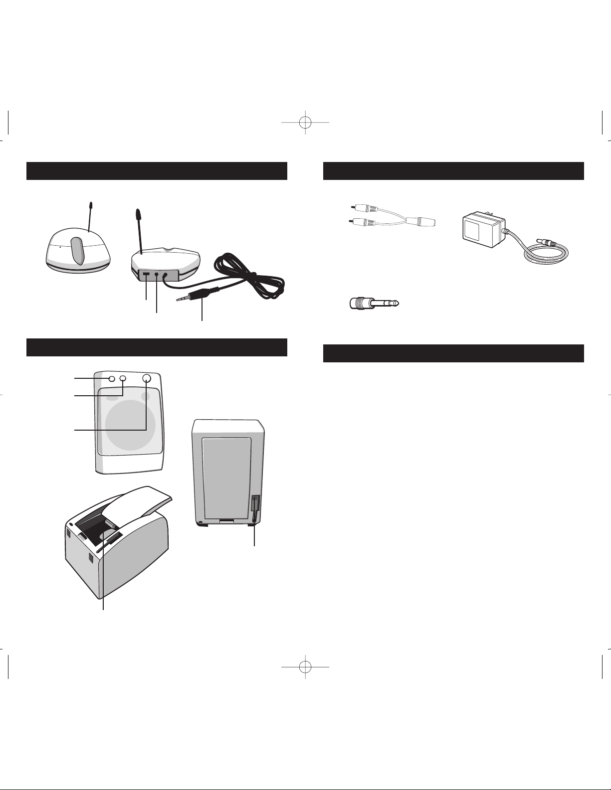
TRANSMITTER
SPEAKER
SUPPLIED ACCESSORIES
INSTALLATION
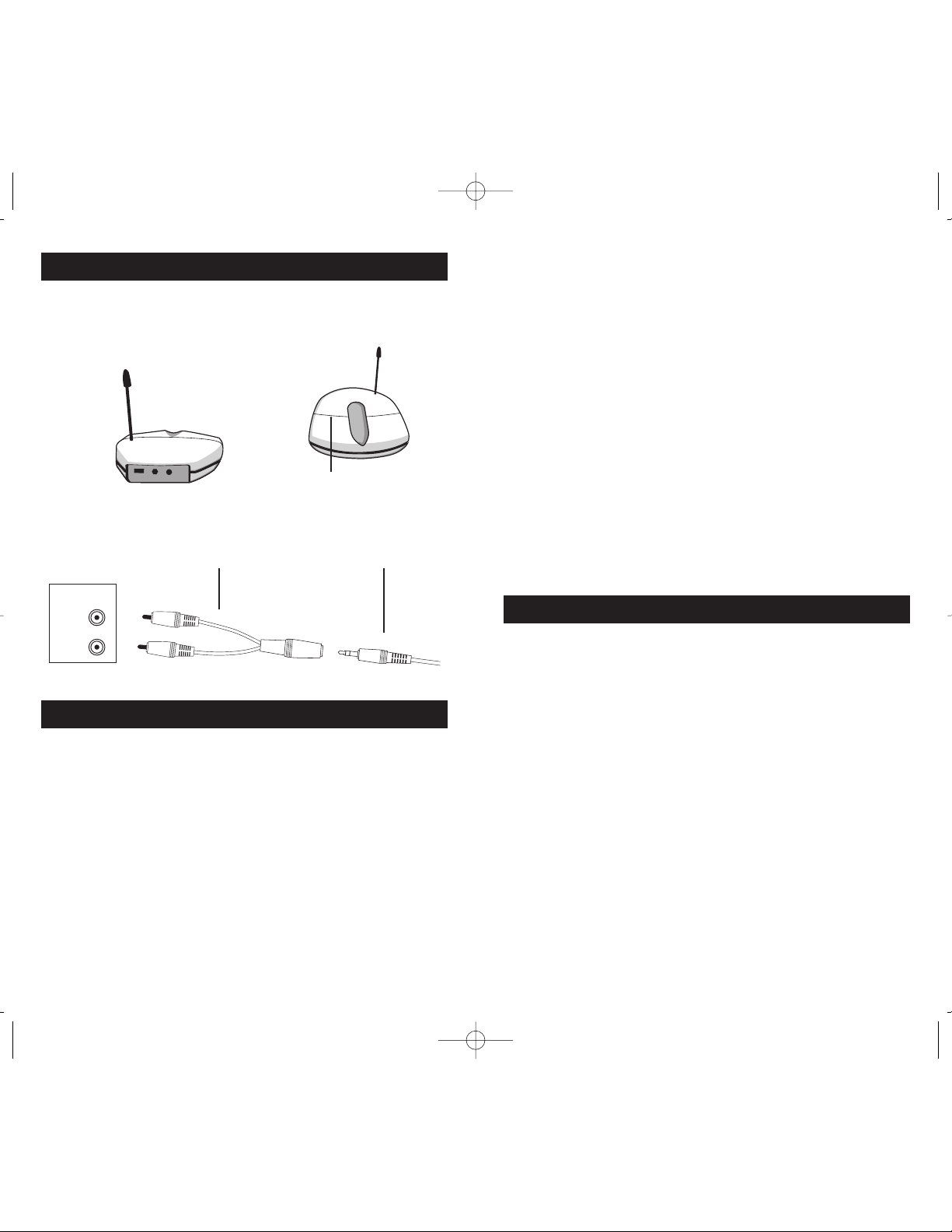
TRANSMITTER
1. Plug the supplied AC power adapter into an electrical outlet near
your audio source. Make sure it is the one for the transmitter
(“DC 12.5V”) —the two for the speakers are marked accordingly.
2. Connect the plug end of the power adapter to the DC jack located
on the back of the transmitter (see diagram). The green LED indicator
light on the top panel will glow when an active audio source is
detected. The LED indicates the unit is transmitting which indicates
the unit is receiving power.
3. Locate the audio input cord on the back of the transmitter. The
3.5 mm standard plug can be used to fit most headphone output
jacks in audio equipment. If you are connecting to the audio output
jacks from a TV, amplifier, etc. then plug the audio input cord into
the “Y” adapter that is provided to adapt standard RCA type audio
plugs for the audio source.
4. Turn on the audio source. The CHANNEL SELECTION CONTROL
is located on the back of the transmitter. Select the desired channel by
using the switch on the back of the transmitter. This channel can later
be switched to achieve optimal audio reception.
This speaker system has automatic ON/OFF control that automatically
turns the transmitter on if there is an audio signal detected and the
green LED light on the top of the transmitter will glow. Once the audio
source is switched off, the ON/OFF control will turn off power and
stop transmitting to the speakers and the green LED will be off (after a
4 minutes timeout period).
Stereo Y adapter cable
(RCA/3.5 mm jack)
(3) AC power adapters
(1 for transmitter, and 1 each for the speakers)
3.5 mm/6.35 mm jack adapter
Transmitter
Front
Speaker Front
Speaker Back
Transmitter
Back
Channel selection control 1, 2, 3
Bass boost button
Auto scan button
Power on/off
and volume knob
Battery compartment
DC IN power supply socket
DC power supply socket
Audio input plug
WSP155_US_IB_REVB.qxd 5/1/07 11:48 AM Page 4
Important: These power units are
intended to be correctly oriented in a
vertical or floor mount position.
76
INSTALLATION
(continued)
This system also features ALC (Automatic Level Controls). ALC
prevents audible distortion of the input signal and maintains an optimal
level of the input signal. The ALC prevents overloads that can occur
from suddenly raising input signal.
SPEAKER RECEIVER
1. You may use either the AC adapter or 4-“D” size alkaline batteries
(sold separately) to power the speaker. Make sure the “Volume
On/Off Control” knob is turned to the off position.
2. If you are using the AC adapter, locate the ones marked “For Speaker”
on the label and plug them into an electrical outlet located near the
location for each speaker. Then, insert the plug end into the DC
INPUT jack located on the back of the speaker. If you are using
batteries, remove the BATTERY DOOR and insert 4-“D” size alkaline
batteries in each speaker making sure to insert the batteries in the
correct polarity as indicated. Once the batteries are inserted correctly,
replace the battery door by first inserting the 2 tabs into the back
cabinet slots then closing it until it snaps in place at the bottom tab.
Check to make sure it is closed securely before moving the speakers.
You can expect the batteries to last approximately 15 hours total
when the speakers are played at a mid-volume level.
3. Position the speakers about 20 feet away from the transmitter
to perform this tuning setup. Turn on the speakers using the
VOLUME control and set them to the desired listening level.
If you hear static or noise and the signal is not clear change the
CHANNEL SELECTION CONTROL on the back of the transmitter
and then try to tune the speakers using the AUTO SCAN button
on each one. The green LED next to the AUTO SCAN button will
illuminate green when a clear signal is being detected. If you still
do not receive a clear signal, make certain that other RF devices
that use RF frequencies such as cordless phones, cell phones and
baby monitors are disabled as they can cause interference.
4. The BASS BOOST switch on the front of the speaker can be used
to enhance the sound depending on your own music preferences.
To improve the bass response of the speaker, simply press the button.
The green LED will illuminate when the BASS BOOST is active.
5. Once you have properly followed the setup procedure, you may
position the speakers in any location within approximately 325 feet
of the transmitter to enjoy quality stereo sound.
OPERATION NOTES
If you notice a disruption of the sound or the signal breaks up, press the
AUTON SCAN button on the speakers to maximize stereo reception.
If you hear interference from other sources, select a different channel on
the back of the transmitter then re-tune the speakers the same way as
described in the setup procedure. You may have to try several settings
to find the one that works best in your home.
When transmitting or receiving over long distances, the signal from the
system will become weak and the stereo indicator light will go dim. If
this occurs, move the speakers to a new location closer to the transmitter
to receive a stronger signal.
For protection of the transmitter and to save power, the transmitter will
cut off automatically in approximately 4 minutes if there is no audio
signal, or if the signal is weak. The green LED indicator light will then
turn off. Once the audio signal is restored, the transmitter will turn on
and the green LED will glow.
Front
Back
Green LED
AUDIO
OUT
STANDARD RCA
CONNECTOR
TRANSMITTER
(AUDIO CORD)
WSP155_US_IB_REVB.qxd 5/1/07 11:48 AM Page 6
IMPORTANT: Do not mix batteries with different chemistry types
(for example, a zinc battery with an alkaline battery). Do not mix
new and used batteries. Do not leave batteries installed in the
product when not in use for long periods.
LINE
OUT
LEFT
RIGHT

98
TROUBLESHOOTING
PROBLEM SOLUTION
No sound A) Check that power adapters and/or batteries are
connected properly and that power is on.
B) Make sure the control knob on the speaker is ON.
C) If using batteries, they may be too weak to
power the speakers. Replace the batteries.
D) Ensure the TV or audio component is on
and that the unit is receiving an adequate
audio signal.
E) The volume control knob on the speaker is set
too low. Adjust the volume if required.
Distorted sound A) Ensure the stereo indicator light on each
speaker is on. If not, adjust the tuning controls
for each until the light is on.
B) Change the position of the CHANNEL
SELECTION CONTROL on the transmitter.
Then press the AUTO SCAN button on each
speaker until the indicator light is on.
C) Speaker batteries may be too weak. Replace
with fresh batteries.
D) The speakers are too far from the transmitter
to receive a strong signal. Move them closer to
the transmitter.
E) The input level of the audio signal is too low.
Turn up the volume on the audio source to
increase the signal level so that the green LED
indicator light on the transmitter glows.
SPECIFICATIONS
Transmission Mode UHF stereo
Carrier Frequency 900 MHz
Operation Voltage Transmitter, 12V 150mA
Speaker, 9V≤ (8 x “D” size Alkaline batteries) 4 per speaker
9V 1000mA adapter (optional)
Frequency Response 40kHz –12.5 kHz (+/-3 dB)
Distortion <4%
S/N ratio
>
–
50dB
Separation
>
–
20dB
Operation distance 150ft*/45m*
* Range may vary by environment.
NOTE: Changes or modifications to this unit not expressly approved by
the party responsible for compliance could void the user’s authority to
operate the equipment.
Operation is subject to the following two conditions:
1) This device may not cause interference, and 2) this device must accept
any interference, including interference that may cause undesired
operation of the device.
12 MONTH LIMITED WARRANTY
WSP155_US_IB_REVB.qxd 4/30/07 5:48 PM Page 8
Audiovox Electronics Corporation (the “Company”) warrants to the original retail purchaser of this
product that should this product or any part thereof, under normal use and conditions, be proven
defective in material or workmanship within 12 months from the date of original purchase, such
defect(s) will be repaired or replaced (at the Company’s option) without charge for parts and repair
labor. To obtain repair or replacement within the terms of this Warranty, the product along with
any accessories included in the original packaging is to be delivered with proof of warranty
coverage (e.g. dated bill of sale), specification of defect(s), transportation prepaid, to the Company at
the address shown below. Do not return this product to the Retailer.
This Warranty is not transferable and does not cover product purchased, serviced or used outside
the United States or Canada. The warranty does not extend to the elimination of externally
generated static or noise, to costs incurred for the installation, removal or reinstallation of the
product. The warranty does not apply to any product or part thereof which, in the opinion of the
company, has suffered or been damaged through alteration, improper installation, mishandling,
misuse, neglect, accident or exposure to moisture. This warranty does not apply to damage caused
by an AC adapter not provided with the product, or by leaving non-rechargeable batteries in the
product while plugged into an AC outlet.
THE EXTENT OF THE COMPANY’S LIABILITY UNDER THIS WARRANTY IS LIMITED TO THE
REPAIR OR REPLACEMENT PROVIDED ABOVE AND, IN NO EVENT, SHALL THE
COMPANY’S LIABILITY EXCEED THE PURCHASE PRICE PAID BY PURCHASER FOR THE
PRODUCT. This Warranty is in lieu of all other express warranties or liabilities. ANY IMPLIED
WARRANTIES, INCLUDING ANY IMPLIED WARRANTY OF MERCHANTABILITY OR
FITNESS FOR A PARTICULAR PURPOSE, SHALL BE LIMITED TO DURATION OF THIS
WARRANTY. ANY ACTION FOR BREACH OF ANY WARRANTY HEREUNDER, INCLUDING
ANY IMPLIED WARRANTY, MUST BE BROUGHT WITHIN A PERIOD OF 24 MONTHS FROM
THE DATE OF ORIGINAL PURCHASE. IN NO CASE SHALL THE COMPANY BE LIABLE FOR
ANY CONSEQUENTIAL OR INCIDENTAL DAMAGES WHATSOEVER. No person or
representative is authorized to assume for the Company any liability other than expressed herein in
connection with the sale of this product. Some states/provinces do not allow limitations on how
long an implied warranty lasts or the exclusion or limitation of incidental or consequential damage
so the above limitations or exclusions may not apply to you. This Warranty gives you specific legal
rights and you may also have other rights which vary from state/province to state/province.
U.S.A.: Audiovox Electronics Corporation, 150 Marcus Blvd., Hauppauge, New York 11788
CANADA: Audiovox Return Center, c/o Genco, 6685 Kennedy Road, Unit 3, Door 16,
Mississauga, Ontario L5T 3A5
 Loading...