

Page 1

owner’s manual
200 Watt Stereo Receiver
with Remote Control
Page 2

CONTENTS
Introduction .......................................... ................................................................ .......................................................................... 3
The FCC Wants You To Know ................................................................................................................................................................. 3
Preparation ..................................................................................................................................................................................... 5
Positioning Speakers ................................................................................................................................................................................ 5
Connecting Speakers ............................................................................................................................................................................... 5
Preparing the Speaker Wires ............................................................................................................................................................. 5
Connecting Speakers to the A and B Terminals ................................................................................................................................. 5
Connecting Program Sources ................................................................................................................................................................... 6
Connecting a Turntable .................................................................................................................................................................... 6
Connecting a CD Player .................................................................................................................................................................... 6
Connecting a Cassette Deck .............................................................................................................................................................. 6
Connecting Another Audio Source ................................................................................................................................................... 6
Connecting the Antennas ........................................................................................................................................................................ 6
AM Antennas ..................... ............................................................................................................................................................... 6
FM Antennas .................................................................................................................................................................................... 7
Installing Batteries ................................................................................................................................................................................... 8
Connecting to AC Power ......................................................................................................................................................................... 8
Operation ........................... ................................................................ ............................................................................................. 9
Using the Sleep Timer ............................................................................................................................................................................. 9
Tuning the Radio ................................................................................................................................................................................... 10
Manual and Automatic Tuning ........................................................................................................................................................ 10
Direct Tuning (Remote Control Only) ............................................................................................................................................. 10
Memory Tuning .............................................................................................................................................................................. 10
Adjusting Balance .................................................................................................................................................................................. 11
Muting the Receiver ............................................................................................................................................................................... 11
Using Headphones ................................................................................................................................................................................ 11
Listening Safely .............................................................................................................................................................................. 11
Cassette Deck Features .......................................................................................................................................................................... 11
Using the Tape Monitor Button ....................................................................................................................................................... 11
Recording a Program Source ........................................................................................................................................................... 11
Using the Reset Button .......................................................................................................................................................................... 11
Troubleshooting .............................................................................................................................. ....... ...... ....... ...... .................... 12
Care .......................................... ................... .................... ................... ................... .................................................... ....... ...... ...... . 13
Specifications .............. .................................................... ................................................... ....... ............. ...... ....... .......................... 14
© 2002 RadioShack Corporation.
2
All Rights Reserved.
Page 3
INTRODUCTION
Your RCA 200 Watt Stereo Receiver operates as the perf ec t co n trol
center for your audio system. It combines 100 watts-per-channel of
clean power with modern styling. It provides connections for one
tape deck, a turntable, a C D player, and one other aud io sourc e, such
as audio fr om a d igital video disk ( DVD) play er. You can also co nnect
up to two pairs of speakers (not supplied) to your receiver.
Additiona l b enefits incl ude:
Digital-Synthesized Tuner — Precisely tunes to AM and FM
stations.
60 Memory Locations — Let you store and recall the frequencies
for up to 30 AM and 30 FM stations.
Automatic Tuning — Searches for the next available AM/FM
station.
Remote Control — Lets you use a single remote control for the
receiver and other compatible com ponents connected to t he receiver.
Tape Monitoring — Lets you lis ten to the actua l recording as you
record, if your tape deck has a tape-monitoring feature.
Built-In Protection Circuits — Automatically turn off t he receiver
to help avoid power surges or short circuit damage.
THE FCC WANTS YOU TO KNOW
Your receiver might cause radio or TV interference even when it is
operating properly. To determine whether your receiver is causing
the interference, turn off your receiver. If the interference goes away,
your receiver is causing it. Try to eliminate the interference by:
• Moving your radio or TV away from the receiver
• Connecting your receiver to an outlet that is on a dif f erent
electrical circuit from the radio or TV
• Contacting your local RadioShack store for help
If you cannot elimina te the in te rference, the FCC requires that you
stop using your receiver.
This system complies with the limits for a Class B digital device as
specified in Part 15 of FCC Rules. These limits provide reasonable
protection against radio and TV interference in a residential area.
However, your equipment mig ht cause TV or ra dio inte rfe re nce ev en
when it is operating properly. To eliminate interference, you can try
one or more of the following corrective measures:
• Reorient or relo cate the receivi ng antenna.
• Increase the distance between the equipment and the radio or
TV.
Note: The remote control requires two AA batteries (not supplied).
WARNING:
expose this product to rain or moisture.
CAUTION:
DO NOT REMOVE COVER OR BACK. NO USERSERVICEABLE PARTS INSIDE. REFER SERVICING TO
QUALIFIED PERSONNEL.
!
Caution: Unplug the cassette deck's power cord when you will not
use the cassette deck for extended periods.
To reduce the risk of fire or shock hazard, do not
CAUTION
RISK OF ELECT RI C SHO CK. DO
NOT OPEN.
TO REDUCE THE RISK OF ELECTRI C SHOCK,
This symbol is intended to alert you to the
presence of uninsulated dangerous voltage
within the product’s enclosure that might be
of sufficient magnitude to constitute a risk of
electric shock. Do not open the product’s
case.
This symbol is intended to inform you that
important operating and maintenance
instructions are included in the literature
accompanying this product.
!
• Use outlets on different electr ic al circuits for the e q uipment and
the radio or TV.
Consult your local RadioShack store if the problem still exists.
Warning: Changes or modifications to this unit not expressly
approved by RadioShack could void the user’s authority to operate
the equipment.
IIIIMMMMPPPPOOOORRRRTTTTAAAANNNNT
T SSSSAAAAFFFFEEEETTTTY
T T
Y
Y Y
IIIINNNNSSSSTTTTRRRRUUUUCCCCTTTTIIIIOOOONNNNSSSS
Careful attention is devoted to quality standards in the manufacture
of your receiver, and safety is a major factor in its design. However,
safety is also your responsibility.
This section lists important information that will help you properly
use and enjoy your receiver.
Heed Warnings — Follow all warnings on the product and in the
operating instructions.
Cleaning — Unplug this product from the wall outlet before
cleaning. Use only a damp cloth for cleaning. Do not use liquid or
aerosol cleaners.
Attachments — Do not use attachments/accessories not
recommended by th e product manufacturer, as they might create a
hazard.
3
Page 4

Water and Moisture — Do not use this product near water ( f or
s
(
)
example, near a b athtub, washbowl, kitchen sink , or laundry tub; in
a wet basement; or near a swimming pool).
Damage Requiring Service — Unplug this product from the wall
outlet and refer servicing to qualified service personnel under the
following conditions:
Accessories — Do not place this product on an unstable cart, stand,
tripod, bracket, or table. The pr oduct m ay fall, causin g serious in jury
to a child or adult, and se rious dam age to the pro duct. Use onl y with
a cart, stand, tripod, bracket, or table recommended by the
manufacturer or s old with the product.
Follow the manufacturer's instructions for mounting, and use a
recommended mounting accessory.
Carts — Move the product on a cart carefully. Quick stops,
excessive force, and uneven surfaces may cause the product/cart to
overturn.
V entilation — Slots and openings in th e cabinet provi de ventil ation,
ensure reliable op eration, and protec t from overheating. Do n ot
block or cover these openings, and do not place the product on a
bed, sofa, rug, o r othe r sim il ar surf ace. Do no t pl ace t he p r od uct in a
built-in installation such as a bookcase or rack unless it provides
proper ventilation as specified by the manufacturer.
Power Sources — Operate this product using only the power
source indicated on its marking label. If you are not sure of your
home's power type, consult your product dealer or local power
company.
Polarization — This product is equipped with a polarized AC line
plug (a plug having one blade wider than the other). This plug will
fit in the power outlet only one way. This is a safety feature. If you
cannot insert the plug fully into the outlet, try reversing the plug. If
the plug still doesn't fit, contact your electrician to re place your
obsolete outlet. Do not defeat the safety purpose of the polarized
plug. If you need an extension, use a polarized cord.
Power-Cord Protection — Route power-supply cords so they are
not likely to be walked on or pinched by items placed on or against
them, paying part icular attention to cords at plugs, convenience
receptacles, and the point where they exit from the product.
Lightning — For added protection for this product during a
lightning storm, or when it is left unattended and unused for long
periods of time, unplug it from the wall outlet and disconnect the
antenna or cable system. This will prevent damage to the product
due to lightning and pow e r-line surge s.
Overloading — Do not overload wall outlets, extension cords, or
integral convenience receptacles, as this can result in a risk of fire or
electric shock.
Objects and Liquids — Never push objects of any kind into this
product through openings, as they may touch dangerous voltage
points or short out parts that could result in a fire or electric shock.
Never spill liquid of any kind on the product.
Servicing — Do not attempt to service this product yourself, as
opening or r em oving c overs m ay e xpos e you to d angerous voltage or
other hazards. Refer all servicing to qualified service personnel.
• When the power-supply cord or plug is damaged.
• If liquid has been spilled or objects have fallen into the product.
• If the product has been exposed to rain or water.
• If the product does not operate normally by following the
operating instructions. Adjust only those controls that are
covered by the operating instructions, as an improper
adjustment of othe r contr ols may r esult in da mage and will often
require extensive work by a qualified technician to restore the
product to normal operation.
• If the produc t has been dropped or damaged in any way.
• When the pro duct exhibits a distinct change in performance.
Replacement Parts — When replacement parts are req ui re d, be
sure the service technician uses replacement parts specif ied by the
manufacturer or having the same characteristics as th e original part.
Unauthorized substi tutions may r esult in fi re, ele ctric shoc k, or other
hazards.
Safety Check — Upon completion of service or repairs to this
product, ask the service tec hnician to perf orm safety checks to
determine th at the product is in proper operating condition.
Wall or Ceiling Mount — The product should be mounted to a
wall or ceiling only as recommended by the manufacturer.
Heat — The product should be situated away from heat sources
such as radiators, h ea t registers, stoves, or other products (including
amplifiers) that produce heat.
Non-use Periods — Unplug the receiver’s power cord when you
will not use it for extended periods.
Power Lines — Locate an outdoor antenna away from power lines.
Outdoor Antenna Grounding — If an outside antenna or cable
system is connected to the receiver, ground the antenna or cable
system so as to provide some protection against voltage surges and
built-up static charges. Article 810 of the National Electrical Code,
ANSI/NFPA 80, pro vides information about proper grounding of the
mast and supporting structure, grounding of the lead-in wire to an
antenna discharge unit, size of grounding conductors, location of
antenna-discharge unit, connection to grounding electrodes, and
requirements for the grounding electrode. See the example below.
Antenna
Lead-In
Wire
Ground Clamp
Antenna
Discharge Unit
Electric
Service
Equipment
NEC -- National Electrical Code
(NEC Section 810-20)
Grounding Conductor
(NEC Section 810-21)
Grounding Clamps
Power Service Grounding
Electrode System
NECArticle 250,Part H
4
Page 5
PREPARATION
Caution: Make all the necessary connections before you plug in or
turn on the receiver.
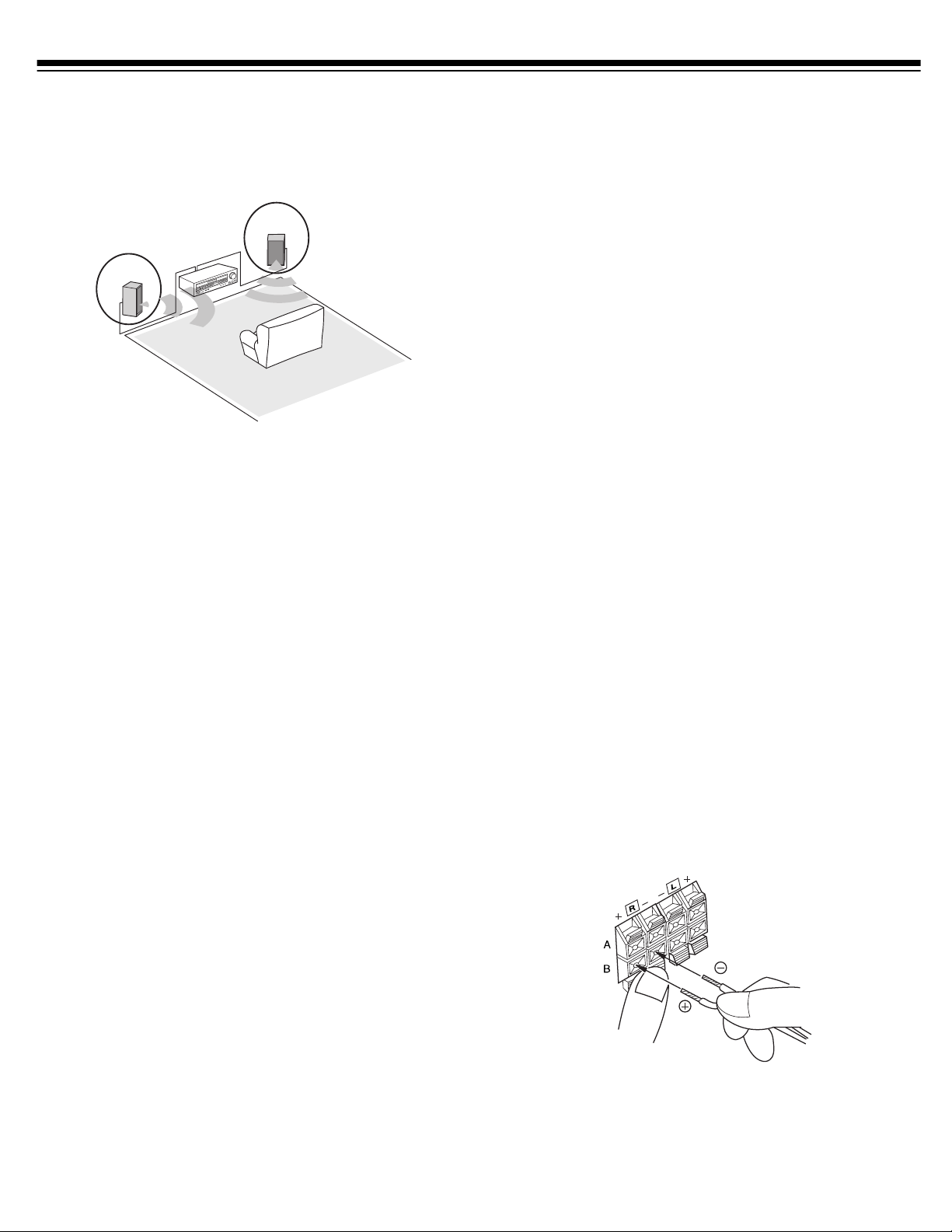
POSITIONING SPEAKERS
Speaker (not sup pl ied) placement ca n make a noticeable difference
in your system’s sound. The guidelines in this section will help you
choose the best locations. After you use your receiver for a while, you
might want to try diff e rent locations for your speakers .
Bass response depends largely on speaker location. For strong bass,
place the speakers in the corn ers of the room. If you wan t even
stronger bass, place the speakers directly on the floor. If the bass is
too strong, move the speakers slightly away from the corners of the
room, or rais e the m 6 to 18 in ches off the floor. Y ou can bu y speake r
stands at your local RadioShack store.
The distance between the speakers should be about the same as the
distance between the normal listening point and the point halfway
between the spea kers. If you place the speakers too clos e together,
you reduce the stereo separation. If you place them too far apart, you
reduce the bass effect and create a hole in the middle of the sound.
Most speakers have a twee ter dispersion angle of about 60 degrees.
Ideally, your listening position should be just inside the overlap area
of the tweeter dispersion. You can angle the speakers toward you for
better stereo effect.
Use 16-gauge (or larger) speaker wire for all speaker connections,
and consider pos sible spea ker locati ons befor e you deci de how much
speaker wire you need.
Preparing the Speaker Wires
Speaker wire consists of two conductors (individual wires) encased
in insulation an d is us ually co lor-coded or marke d with a ridg e along
one side so you c an ident if y ea ch condu cto r. Use these ma rkin gs a s a
guide to help you properly connect the speakers to your receiver.
Follow these steps to prepare the speaker wires.
1. Cut the speaker wires to the necessary length.
2. Separate the wires about 4 inches on each end.
3. Using a wire stripper, caref ully str ip ab out 3 /4 inch of i nsul ation
from the end of each conductor.
4. Twist the end of each co nductor to secure any loose wire
strands.
Caution: Twisting the end of each conductor helps pr event a short
circuit be cause st ray spea ker w ire s trands d o not touc h oth er spea ker
terminals or any other receiver terminals.
Connecting Speakers to the A and B Terminals
Notes:
• Be sure you connect the receiver’s right and left positive (+) and
negative (–) terminals to the speaker’s corresponding right and
left positive (+) and negative (–) terminals.
• Fully insert the speaker wires to ensure a good connection.
Leave extra wire at the back of the receiv er so you do not
disconnect the wires when you move the receiver.
Follow these steps to connect each speaker (A right or left or B right
or left).
1. Press open the receiver’s positive (+) red lever for the speaker
you want to connect and insert the ridged or color-coded
conductor’s end into the small hole. Release the lever to secure
the conductor.
CONNECTING SPEAKERS
Follow these gu idelines whe n yo u select and con nect speakers.
• Only connect speakers that are rated at between 8 and 16 ohms.
• Be sure you properly connect all speakers.
• Do not connect two pairs of speakers to a single set of ter mi na ls
(A or B) at the same time. When you use two pairs of speakers,
connect one pa ir to the
pair to the
• RCA and other high-quality speakers have color-coded speaker
terminals (red for positive polarity and black for negative
polarity). Use these color-coded terminals as a guide to help you
properly connect the speakers to the receiver.
B SPEAKERS terminals.
A SPEAKERS terminals and the other
2. Press op en the receiver’s negativ e ( –) black lever for the same
speaker and i nser t t he ot her c on ductor ’s end into the small h ole .
Release the lever to secure the conductor.
5
Page 6

3. Connect the ridged or color-coded conductor’s loose end to the
speaker’s positive (+) terminal.
4. Connect the remaining loose conductor to the spe aker’s negative
(–) terminal.
CONNECTING PROGRAM SOURCES
Note: Use shielded audio cables with phono connec tors for all audio
connections.
You can connect up to four external program sources to your
receiver.
CONNECTING THE ANTENNAS
In many areas, the supplied indoor AM loop and FM antennas
provide satisfactory reception.
AM Antennas
Assemble the supplied AM antenna’ s base by swinging the base in the
direction of the arrow and inserting the antenna’s bottom tabs into
the base’s slot. If the receiver is in a rack or on a shelf and there is no
room for the AM loop antenna, use two screws (not supplied) to
mount the base on the wall or another location as shown.
Connecting a Turnt able
Connect a turntable with a magn etic cartridge only. Some older
turntables use a ceramic-type cartridge that does not work with this
system.
Connect the turntable’s left and right cables to the re ceiver’s
and
R (right) PHONO IN jacks. Then connect th e turntable ’s ground
wire to the receiver’s
GND screw terminal.
L (left)
Connecting a CD Player
To connect a CD player to the receiver, connect the CD player’s left
and right output jacks to the receiver’s
L and R CD IN jacks.
Connecting a Cassette Deck
You can connect a cassette deck to the
Connect the cassette deck’s output jacks to the
connect the cassette deck’s input jacks to the
TAPE MONITOR jacks.
PLAY jacks, and
REC jacks.
Connecting Another Audio Source
Connect the audio outputs of another audio source, such as the
audio from a laser disc player, TV, or VCR to the
AUX jacks.
Attach the antenna wires from the AM loop antenna to the AM and
GND (ground) ANTENNA terminals.
Place the antenn a on a flat surface and rotat e it for the best AM
reception.
Notes:
• Keep the AM loop antenn a connected even when you use
another indoor antenna or an outdoor AM antenna.
• Ensure that the antenna does not touch the receiver or any other
metal object.
• Do not place the an tenna near a CD p layer, a personal comp uter,
or a TV set.
• If the wire between the AM loop antenna and your receiver is
too short, you can add extra wire, available at your local
RadioShack store.
6
Page 7

You can als o use an optional RadioShack shortwave ant enna kit,
which makes an excellent outdoor AM antenna . Connect t he outdo or
AM antenna wire to the r ec eiver’s
AM ANTENNA terminal as sho wn .
FM Antennas
3. Fold back the shielding from the inner insulation.
4. Remove about 1 inch of the inner insulation from around the
center wire.
5. Pull the shielding to one side. Connect the center wire to the
receiver’s
secure any loose wire strands, and connect it to the
ANTENNA terminal.
FM 75ΩΩΩΩ ANTENNA terminal. Twist the shielding to
GND
Connect the supplied FM antenna to the
FM 300ΩΩΩΩ ANTENNA
terminal as shown then extend it.
For better FM reception, you can also use a rabbit-ear TV antenna
(for indoor use onl y) or an outd oor VHF TV an tenna . To connect the
TV antenna to the receiver, you need a VHF/ UHF/FM splitter (not
included). Radi oShack stor e s c arry a f ull li ne of qu ality a ntenna s and
antenna connection accessories.
Warning: To prevent injury, read and follow all cautions and
warnings that accompany the outdoor antenna. Us e 75- ohm coaxial
cable to connect an outdoor antenna to the receiver.
For the best radio reception, use an outdoor antenna. Follow these
steps to connect an outdoor FM antenna to the receiver using 75
ΩΩΩΩ
coaxial cable.
Caution: The cable’s shielding should only touch the
ANTENNA terminal.
GND
Note: Grounding is not necessary for reception, but we recommend
it for better FM reception and to avoid damage from lightning when
you use an outdoor FM antenna. Use a separate piece of thick
polyvinyl insulated wire to connect the
GND ANTENNA terminal to
an earth ground, such as a metal cold-water pipe.
Warning: Never connect a wire to a gas pipe for grounding since
sparks might ignite the gas.
Note: If your antenna has 300
300ΩΩΩΩ ANTENNA terminals.
ΩΩΩΩ twin-lead cable, co nnect it to the FM
1. Disconnect the supplied FM antenna from the receiver’s
300ΩΩΩΩ ANTENNA
2. With a stripping tool, remove about 1
terminal.
1
/2 inches of the 75Ω
cable’s outer ins ulation to expos e the cable’s shield ing.
FM
Ω
ΩΩ
7
Page 8

INSTALLING BATTERIES
CONNECTING TO AC POWER
Cautions:
• Use only fresh batteries of the required size and recommend ed
type.
• Do not mix old and new batteries, different types of batteries
(standard, al ka line, o r r ech argeable), or re chargeable batterie s of
differ ent capacities. Your remote control requires two AA
batteries (not included) for power. For the best operation and
longest life, we recommend alkaline batteries, available at your
local RadioShack store.
1. To remove the battery compartment cover, push the
compartment ’s tab in the direction of the arrow, then lift o ff the
cover.
2. Place two fresh AA ba tteries in the compartment as indicated by
the polarity symbols (+ and –) marked inside.
3. R ep lace the batter y compartment cov er.
When the range is reduced or the remote stops operating properly,
replace the batteries.
Warning: To prevent electric shock, do not use this polarized plug
with an extension cord, receptacle, or other outlet unless you can
fully insert the blades to prevent blade exposure.
Before you plug in the receiver’s power cord, double check all other
connections.
To power the receiver, plug the supplied power cord into a standard
AC outlet. The power cord’s plug is polarized and fits only one way.
The STAND BY indicator lights when the receiver is plugg ed in but
turned off.
Note: The receiver has a built-in circuit to protect it against
overheating or short circuits. If your receiver automatically turns off
(stand by mode), let it cool for several minutes. If the receiver
overheated, it should play normally when you turn it back on. If
there is a short cir cui t in your rece iver, it will turn of f again when y ou
turn on the receiver. If this happens, check with your local
RadioShack store for service.
Warning: Dispose of old batteries promptly and properly. Do not
burn or bury them.
Caution: If you do not plan to use the remote with batteries for a
month, remove the batteries. Batteries can leak chemicals that can
destroy electronic parts.
8
Page 9

OPERATION
AM
A/B
TAPE
MONITOR
AUX
POWER
CD
PHONO
PHONES
FM
SPEAKERS
Warning: To prevent possible hearing loss, turn VOLUME to MIN
before you turn on the receiver or change the program source. After
you turn on the receiver or change the program source, adjust
VOLUME to a comfortable lis tening level.
TUNING
MODE
FM MODE
TUNING DOWN
TUNING UP
VOLUME
LOUDNESS
BALANCE
PRESET
SCAN
MEMORY
TREBLE
BASS
To listen to a source other than the one connected to the
MONITOR
disappears. Then press
jacks, press TAPE MONITOR so TAPE MON
CD, PHONO, or AUX (CD, PHONO, or
AUX appears).
TAPE
You can use the supplied remote control by pointing it at the
receiver’s front pan el and pr essing the desired button(s). Many
buttons on the remote control work the same as buttons on the
receiver’s front panel. Use these buttons exactly as you would use the
corresponding buttons on the receiver.
1. Press
POWER to turn on the re ceiver. It takes about 5
seconds to hear sound.
2. Select the speakers. An indi ca tor l ights ne xt to the
A and/or B to
show which speakers are on.
If you connected speakers only to the
terminals, press
speakers. Do not pr ess both
SPEAKERS A (or B) to turn on only those
SPEAKERS A and B because doing
A (or B) SPEAKERS
so turns off all speakers even though both indicators are on.
If you connected speakers to both the
A and B SPEAKERS
terminals, you can:
• Press
SPEAKERS A or B to turn on either pair of speakers
for a two-speake r effect.
• Press
SPEAKERS A and B to turn on both pairs of speakers
for a four-speaker effect.
Press
SPEAKERS A and/or B to turn off all speakers so you can
listen privately with headphones (see “Using Headphones” on
Page 11).
3. Select a program source.
4. Turn
5. To adjust the tone, turn
VOLUME clockwise to increase the volume or
counterclockwise to decrease it. Or, you can use
and
8on the remote control.
BASS and TREBLE toward + or –. To
VOLUME 9
increase the high and low ranges of sound at low volume, press
LOUDNESS. (To turn off this feature, press LOUDNESS again.)
6. To adjust the balance of sound between the left and right
speakers, see “Adjusting Balance” on Page 11.
7. When you finish using the receiver, press
POWER to turn it off.
USING THE SLEEP TIMER
The sleep timer lets you set the recei ver to play for up t o 90 min utes,
then automatically turns off.
1. To set the timer, turn on the receive r then press
remote control. The display dims and SLEEP 90 SLEEP
appears.
2. To set the sleep timer for less than 90 minutes, repeatedly press
SLEEP to decrease the time by 10 minutes for each press of the
button. Once you select the ti m e, the receiver displays the
program source. (SLEEP stays on the display in small letters
until automatic shut-off.)
3. To briefly see the time remaining, press
SLEEP once.
SLEEP on the
To tune to a radi o s tation, see “ D irect Tuning (Remote Control
Only)” on Page10.
To listen to signals from the component connected to the
MONITOR
jacks, press TAPE MONITOR so TAPE MON appears.
TAPE
9
Page 10

TUNING THE RADIO
Memory Tuning
Your receiver has four types of electronic tuning — manual,
automatic, direct, and memory.
Note: To listen to stations with weak signals, we recommend manual
tuning.
Manual and Automatic Tuning
1. Press FM or AM on the front panel ( or on the remote control) to
select the desired band. The receiver tunes to that band and
displays the f r equency last selected.
Note: If CH appears on the right side of the display, press
TUNING MODE to switch from preset to manual-tuning mode.
MANUAL briefly appears.
2. To manually select the next higher or lower frequency, press
TUNING UP or DOWN. Hold down UP or DOWN to rapidly
scan up or down through the freq uencies. Rel ease the butto n to
stop scanning.
To automatically search for the next higher or lower frequency with a
strong signal, briefly hold down
receiver searches up or down the band, stopping on the next
frequency with a strong signal.
TUNING UP or DOWN. The
Memory tuning lets you instan tly tune to a stored fr equency. You c an
store up to 30 AM and 30 FM frequencies in the receiver’s memory.
The receiver automatically stores the first 30 stations found in the
selected band into the memory. You can also manuall y store a stati on
into memory.
AAAAuuuuttttoooommmmaaaattttiiiiccccaaaall
1. Press FM or AM on the front panel (or on the remote control) to
select the desired band. The receiver tunes to that band and the
last selected frequency appears.
2. Hold do w n
CH appear and the receiver scans through the frequencies,
beginning with the lo w en d (87. 5 M Hz for FM or 530 kHz for
AM).
3. When the receiver finds a station, it stores it in the first memory
channel, the sele cted CH number ap pears, and th e recei ver looks
for the next station. W hen the re ceive r fi nds th e thir tiet h sta tion
or when it re aches the h igh end of t he fre quency ra nge, MEMORY
disappears and the r eceiver tunes to the lowes t frequ ency stati on
in the band.
Repeat these steps to automatically store stations in the other band.
lly S
y Sttttoooorrrriiiinnnng
llll
y Sy S
MEMORY for more than 2 seconds. MEMORY and
g SSSSttttaaaattttiiiioooonnnnssss
g g
Notes:
• TUNED appears when the rece ived signal is strong.
• STEREO appears when the received FM broadcasts are in
stereo.
• If you press
TUNING DOWN at the bottom of the frequency range, the
frequency at the opposite end of the range appears.
TUNING UP at the top of the frequency range or
Direct Tuning (Remote Control Onl y)
1. Press FM or AM on the front panel (or on the remote control) to
select the desired band. The receiver tunes to and displays the
frequency last selected in that band.
2. Press
3. Enter the desired frequency using the remote control’s number
DIRECT TUNING on the remote control. DIRECT IN
scrolls by, followed by AM
MHz for FM. The first – flashes.
buttons.
Notes:
• If you press
automatical ly appears. If you als o press the zero, the
frequency that appears would be 100.30.
• The last zero always appears automaticall y in both FM and
AM frequencies.
• If you do not press a key within 5 seconds, the receiver exits
direct tuning . S tart over at Step 2.
1 to enter a FM frequency, such as 103.5, 10
– – – – kHz for AM or FM ––– . ––
MMMMaaaanu
nuaaaall
lly
y SSSSttttoooorrrriiiinnnng
nunu
llll
y y
Follow these steps to manually store a station, or to replac e a station
already stored in memory.
1. Press
2. Tune to the desire d station (see “Manual and Automatic Tuning”
3. Press
4. While MEMORY flashes, press
5. Press
Notes:
• If you store a frequency in a memor y ch annel that already
• If your receiv er is di sco nnect ed fr o m AC power for sever al day s,
FM or AM on the front panel (or on the remote control) to
select the desired band. The receiver tunes to and displays the
frequency last selected in that band.
Note: If CH appears on the right side of the display, press
TUNING MODE to switch to manual-tuning mode. MANUAL
briefly appears.
on Page 10).
MEMORY. MEMORY flashes on the display.
desired memory channel number appears.
MEMORY again to store the station immediately. Or, wait
about 5 seconds and the station is automatically stored in the
selected channel .
contains a frequency, you replace the previous frequency.
it loses all the stored frequencies.
g a S
a Sttttaaaattttiiiioooonnnn
g g
a Sa S
TUNING UP or DOWN until the
10
Page 11

TTTTuuuunnnniiiinnnng
g tttto
o a S
a Sttttaaaattttiiiioooon
g g
o o
a Sa S
1. Press FM or AM on the front panel ( or on the remote control) t o
select the desired band. The receiver tunes to that band and the
last selected frequency appears.
NNNNooootttteeee:::: If CH does not appear on the right side of the display,
press
TUNING MODE to switch to memory-tuning mode.
PRESET briefly appears.
2. Press
TUNING UP or DOWN (o r PRESET CALL 9 and 8 on
the remote control) to tune to the next higher or lower station
stored in memory.
Or, press
memory. The receiver tunes to each station for abou t 5 se conds.
When you hear th e station you want to listen to, press
SCAN again.
n iiiin
n MMMMeeeemmmmoooorrrryyyy
n n
n n
PRESET SCAN to scan through the stations in
PRESET
• Set the volume to its lowest setting before you begin listening.
After you begin listening, adjust the volume to a comfortable
level.
• Do not listen a t ex t r em ely high volume levels. Extended highvolume listening can lead to permanent hearing loss.
• Once you set the volume, do not increase it. Over time, your
ears adapt to the volume level, so a volume level that does not
cause discomfort might still damage your hearing.
CASSETTE DECK FEATURES
You can connect a cassette dec k to the receiver . S electing TAPE
MONITOR
connected to the receiver’s
lets you hear the playback from the cassette deck you
TAPE MONITOR jacks.
You can also tune to a station in memory by using the remote
control’s number buttons to ente r the channel number. For
single-digit channels, enter
Channel 6).
Notes:
• To improv e th e r ecep tio n of wea k FM sta ti ons, pr ess
This reduces signal noise, but you hear monaural instead of
stereo sound.
• For stations with a weak signal, we recommend manual tuning.
0 first (for example, enter 06 for
FM MODE.
ADJUSTING BALANCE
The BALANCE control lets you adjust the sound balance between
the left and right speakers. If you properly position the speakers and
your listening area is centered between them, the center control
setting is usually best (see “Positioning Spe akers” on Page 5).
For an unusual speaker placement, press
or select any source and play a mo naural audio source. Turn
BALANCE until you hear the sound coming equ al ly from each
speaker when you are in the listening area.
AM to select the AM band
Using the Tape Monitor Button
Press TAPE MONITOR. TAPE MON appears, along with the last
program source you selected. You can hear the playback or monitor
a recording from the cassette deck you connected to the receiver’s
TAPE MONITOR jacks.
The
TAPE MONITOR REC jacks continue to output the previously
selected sound source after you press
To return to the previous source, press
TAPE MON disappears.
Note: If you press
neither playing nor re cording, the receiver mutes the current audio
source. To hear the audio source, press
MON disappears.
TAPE MONITOR when that cassette deck is
TAPE MONITOR.
TAPE MONITOR again so
TAPE MONITOR so TAPE
Recording a Program Source
The receiver sends the audio of the program source you select—
TAPE MONITOR, AUX, CD, FM/AM (tuner), or PHONO—to the
TAPE MONITOR REC jacks. The VOLUME control does not affect
the level of the signal going to the tape decks.
MUTING THE RECEIVER
To temporar ily mute the sound, press MUTING on the remote
control. The MUTE indicator on the receiver flashes. Press
again to restore th e audio level. The MU TE indicator turn s off.
MUTING
USING HEADPHONES
To listen with headphones (not supplied), ins er t the headphones’ 1/4inch plug into the receiver’s front panel
speakers and listen with headphones without disturbing others,
press
SPEAKERS A and/or B so both indicators are off.
Listening Safely
To protect your hearing, note the following when using headphones.
PHONES jack. To silence the
When you record a progra m source usin g the cassette deck, you hear
the program source’s signal immediately after you record it onto the
tape, if the c as sette deck you connected ha s a th ree-head moni tor
function. (Be sure to r ead th e own er’ s ma nua l fo r yo ur c as set te de ck. )
USING THE RESET BUTTON
If the receiver is subjected to a strong magnetic field or an electric
shock, it might operate erratically. If this happens, turn off the
receiver and press the rear panel
paperclip or other pointed object.
Caution: Pressing
memory.
RESET clears everyth ing stored in the receiver’s
RESET button with a straightened
11
Page 12

TROUBLESHOOTING
If the receive r is no t wo rki ng as it sho uld , the f ollo win g sugge sti ons migh t help. If you fo llow t he sugges tio ns in th is c hart and the r ece iver st ill
does not work properly, contact your local RadioShack store for assistance.
Problem Cause Suggestion
Power does not turn on. Power cord is disconnected. Plug in the power cord.
No sound. Incorrect connections. Check and correct the connections.
The mute function is activated. Press
The volume is turned down. Turn up the volume.
Speaker wires are disconnected. Connect the speaker wires.
Neither set of speakers is selected. Press
SPEAKER A
Both
of speakers is connected.
TAPE MONITOR
Sound from only one speaker. One of the speaker wires or the input cord is
disconnected.
BALANCE
High noise level. Station not correctly tuned. Adjust tuning.
Antenna not connected. Connect antenna.
FM antenna still coiled or is not pointing in the correct
direction.
AM loop antenna not pointing in the correct direction. Adjust the AM loop antenna.
Noise is coming from another electrical appliance. Try using an AC line noise filter to reduce the noise.
Automatic tuning does not stop when
searching for stations.
Remote control does not work. Batteries are weak or missing. Install fresh batteries.
Stations are too weak. Use a better antenna.
Poor angle or too great a distance from the remote sensor
window.
There is an obstacle between you and the remote sensor
window.
A fluorescent light is shining on the remote sensor
window.
and B are selected when only one set
is selected. Press
is set too far to one side. Set
MUTING
SPEAKER A
SPEAKERS A
Press
that are not connected.
TAPE MONITOR
Check all connections.
BALANCE
Stretch both ends of the antenna taut and reposition
the antenna.
Use the remote within the effective range.
Change your position or remove the obst acle.
Turn off the light.
.
or B.
or B to turn off the speakers
TAPE MON
so
to the center position.
turns off.
12
Page 13

CARE
Keep the re ceiv er dry ; i f it ge ts wet , w ip e it d ry imm ed iatel y. Use and
store the re ce iver only in normal temperat ure environments. Handl e
the receiver carefully; do not drop it. Keep the receiver away from
dust and dirt, and wipe it with a damp cloth occasionally to keep it
looking new.
Modifying or tampering with the receiver’s internal components can
cause a malfunction and might invalidate its warranty and void your
FCC authorization to operate it.
This receiver has been manufactured to the specifications of
RadioShack and is co vered b y a limited wa rranty fr om Radi oShack. If
your receiver is not operating as it should, take it to your local
RadioShack store or call 1-800-THE-SHACK for assistance.
13
Page 14

SPECIFICATIONS
Amplifier
Power Output ................................................................................................................................................. 100 Watts per Channel into 8 Ohms
From 40 to 20,000 Hz,
With No More than 0.5% Total Harmonic Distortion
Measured Pursuant to th e F ed er al Trade Commission’s
Trade Regulation Rule on Amplifier Output Power Claims
Input Sensitivity/Impedance:
Phono .......................................................................................................................................................................................... 2.5 mV/47 kohms
CD, AUX, TAPE MONITOR .................................................................................................................................................... 200 mV/47 kohms
Signal-to-Noise Ratio (IHF, Short-Circuited, A Network):
Phono ............................................................................................................................................................................................................. 72 dB
CD, AUX, TAPE MONITOR ........................................................................................................................................................................ 95 dB
FM Tuner
Frequency Range ............................................................................................................................................................................ 87.5–108 MHz
Usable Sensitivity Mono ................................................................................................................................................................. 15 µV/m, EMF
Signal-to-Noise Ratio:
Mono ...............................................................................................................................................................................................................68 dB
Stereo ............................................................................................................................................................................................................. 63 dB
Distortion Stereo................................... ..... ...... ................................................................................................................................... 0.5% (1 kHz)
Alternate Channel Selectivity ........................................................................................................................................................................ 45 dB
Stereo Separation ....................................................... ................................................... ............................................. ...... ................. 35 dB (1 kHz)
AM Tuner
Frequency Range ................................................................................................................ .................................................. ...... ..... 530–1720 kHz
Sensitivity (IHF, Loop Antenna) ............................................................................................................................................................. 500 µV/m
Selectivity ...................................................................................................................................................................................................... 25 dB
Signal-to-Noise Ratio .................................................................................................................................................................................... 35 dB
General
Power Requirements .............................................................................................................................................................. 120 Volts AC, 60 Hz
Power Consumption ............................................................................................................................. ... .. ...... ........................................ 190 Watts
Dimensions (HWD) ............................................................................................................. 5
11
/16 × 169/16 ×137/16 Inches (144 × 420 × 321 mm)
Weight ............................................................................................................................................................................................... 14 lb (6.3 kg)
Specifications are typical; individual units might vary. Specifications are subject to change and improvement without notice.
14
Page 15

NOTES
15
Page 16

Limited Two-Y ear Warranty
This product is warranted by RadioShack against manufacturing defects in material and workmanship under normal use for two (2) yea rs from the date of purchase from RadioShack companyowned stores and authorized RadioShack franchisees and dealers. EXCEPT AS PROVIDED
HEREIN, RadioShack MAKES NO EXPRESS WARRANTIES AND ANY IMPLIED WARRANTIES,
INCLUDING THOSE OF MERCHANTABILITY AND FITNESS FOR A PARTICULAR PURPOSE,
ARE LIMITED IN DURATION TO THE DURATION OF THE WRITTEN LIMITED WARRANTIES
CONTAINED HEREIN. EXCEPT AS PROVIDED HEREIN, RadioShack SHALL HAVE NO LIABILITY OR RESPONSIBILITY TO CUSTOMER OR ANY OTHER PERSON OR ENTITY WITH RESPECT TO ANY LIABILITY, LOSS OR DAMAGE CAUSED DIRECTLY OR INDIRECTLY BY USE
OR PERFORMANCE OF THE PRODUCT OR ARISING OUT OF ANY BREACH OF THIS WARRANTY, INCLUDING, BUT NOT LIMITED TO, ANY DAMAGES RESULTING FROM INCONVENIENCE, LOSS OF TIME, DATA, PROPERTY, REVENUE, OR PROFIT OR ANY INDIRECT,
SPECIAL, INCIDENTAL , OR CONSEQUENTI AL DAMAGES, EVE N IF Radio Shack HAS BEEN ADVISED OF THE POSSIBILITY OF SUCH DAMAGES.
Some states do not allow limitations on how long an implied warranty lasts or the exclusion or limitation of incidental or conseq uen tial da ma ges, so the ab ove lim itati o ns or ex clusi on s may no t app ly to
you.
In the event of a p roduct defect dur ing the warranty p eriod, take the pr oduct and the Rad ioShack
sales receipt as proof of purchase date to any RadioShack store. RadioShack will, at its option, unless otherwise pro vi de d b y law : (a ) correct t he def ect b y p rod uct repair without charge for parts and
labor; (b) replac e the product with o ne of the same or si milar design; or (c ) refund the purcha se
price. All repla ced parts and pro ducts, and products on which a refun d is ma de, becom e the pr operty of RadioShack . New or recon ditioned parts an d products m ay be used in the performance o f
warranty service. Repaired or r eplaced parts and products are wa rranted for the remainder o f the
original warranty period. You will be charged for repair or replacement of the product made after the
expiration of the warranty period.
This warranty does not cover: (a) damage or failure caused by or attributable to acts of God, abuse,
accident, misuse, i m pro per o r abn or ma l usa ge , f ailur e t o follow instructions, improper insta llati on o r
maintenance, alter ation, lightning or oth er incidence of excess voltage or current; (b) any repairs
other than those provide d by a RadioShack Authorized S ervice Facility; (c) consumab les such as
fuses or batteries; (d) cosme tic da mage; ( e) trans portat ion, shippi ng or in suranc e costs; or ( f) costs
of product removal, installation, set-up service adjustment or reinstallation.
This warranty gives you specific legal rights, and you may also have oth er rights which vary from
state to state.
RadioShack Customer Relations, 200 Taylor Street, 6th Floor, Fort Worth, TX 76102
12/99
RadioShack Corporation
Fort Worth, Texas 76102
31-5006
01A02 Printed in China
 Loading...