

Page 1

owner’s manual
STA-3850
STEREO RECEIVER
Page 2
INTRODUCTION
Your RCA STA-3850 Stereo Receiver operates as the perfect
control center for your audio system. It combines 50 wattsper-chann el of clean power with modern styling. It provides
connections for one tape deck, a turntable, a CD player, and
one other audio source, such as au di o fro m a di git al video d isk
(DVD) player. You can also connect up to two pairs of
speakers (not supplied) to your receiver.
Additional features include:
Digital-Synthesized Tuner — Precisely tunes to AM and FM
stations.
60 Memory Locations — Let you store and recall the
frequencies for up to 30 AM and 30 FM stations.
Automatic Tuning — Searches for the next available AM/FM
station.
Tape Monitoring — Lets you listen to the actual recording as
you record, if your tape deck has a tape-monitori ng feature.
Built-In Protection Circuits — Automatically turn off the
receiver to help avoid power surges or short circuit damage.
WARNING: To reduce the risk of fire or shock hazard, do not expose
this product to rain or moisture.
CAUTION
RISK OF ELECTRIC SHOCK.
DO NOT OPEN.
CAUTION: TO REDUCE THE RISK OF ELECTRIC SHOCK, DO
NOT REMOVE COVER OR BACK. NO USER-SERVICEABLE
PARTS INSIDE. REFER SE RVICING TO Q UALIF IED PERS ONNEL.
This symbol is intended to alert you to the
presence of uninsulated dangerous voltage
within the product’s enclosure that might be of
sufficient magnitude to constitute a risk of
electric shock. Do not open the product’s case.
This symbol is intended to inform you that
important operating and maintenance
!
instructions are included in the literature
accompanying this product.
!
Caution: Unplug the cassette deck's power cord when you will
not use the cassette deck for extended periods.
Remote Control — Lets you use a single remot e control for the
receiver and other compatible components connected to the
receiver.
Note: The remote control requires two AA batteries (not
supplied).
We recommend you record the receiver’s serial number here.
The number is on the receiver’s back panel.
Serial Number:_____________________________________.
FCC NOTICE
This system complies with the limits for a Class B digital
device as specified in Part 15 of
FCC Rules
provide reasonable protection against radio and TV
interference in a residential area. However, your equipment
might cause TV or radio interference even when it is operating
properly. To eliminate interference, you can try one or more of
the following corrective measures:
• Reorient or relocate the receiving antenna.
• Increase the distance between the equipment and the radio
or TV.
• Use outlets on different electrical circuits for the
equipment and the radio or TV.
Consult your local RadioShack store if the problem still exists.
Warning: Changes or modifications to this unit not expressly
approved by RadioShack could void the user’s authority to
operate the equipment.
. These limits
©
1999 Tandy Corporation.
All Rights Reserved.
2
Page 3

IMPORTANT SAFETY INSTRUCTIONS
Careful attention is devoted to qualit y stan da rd s in the man uf a cture o f
your cassette deck, and safety is a major factor in its design. However,
safety is also your responsibility.
This section lists important informatio n that will help you prope rly use
and enjoy your cassette deck.
instructions before using your cassette deck.
retain them for future reference.
Heed Warnings
operating instructions.
Cleaning
Use only a damp cloth for cleanin g. Do not use liquid or aerosol
cleaners.
Attachments
recommended by the product manufacturer, as they might create a
hazard.
— Follow all warnings on the product and in the
— Unplug this product from the wall outlet be fore cleaning.
— Do not use attachments/accessories not
Water and Moisture
example, near a bathtub, washbowl, kitchen sink, or laundry tub; in a
wet basement; or near a swimming pool).
Accessories
tripod, bracket, or table. The product may fall, causing serious injury
to a child or adult, and serious damage to the pro duct. Use only with a
cart, stand, tripod, bracket, or table recommended by the manufacturer
or sold with the product. Follow the manufacturer's instructions for
mounting, and use a recommende d mounting accessory.
— Do not place this product on an unstable cart, stand,
Carts
stops, excessive force, and uneven surfaces may cause
the product/cart to overturn.
Ventilation
ensure reliable operation, and protect from overheating. Do not block
or cover these openings, and do not place the product on a bed, sofa,
rug, or other similar surface. Do not place the product in a built-in
installation such a s a bookcase or rack unless it provides proper
ventilation as specified by the manufacturer.
Power Sources
indicated on its marking label. If you are not sure of your home's power
type, consult you r product dealer or local power company.
Polarization
plug (a plug having one blade wider than the other). This plug will fit
in the power outlet only one way. This is a safety feature. If you cannot
insert the plug fully into the outlet, try reversing the plug. If the plug
still doesn't fit, co ntact your electrician to replace your ob solete outle t.
Do not defeat the safety purpose of the polarized plug. If you need an
extension, use a polarized cord.
— Slots and openings in th e cabinet provide ventilation,
— Operate this product using only the power source
— This product is equipped with a polarized AC line
Power-Cord Protection
likely to be walked on or pinched by items placed on or against them,
paying particular attent io n to cords at plugs, convenience receptacles,
and the point where they exit from the product.
Lightning
storm, or when it is left unattended and unused for long periods of time,
unplug it from the wall outlet and disconnect the antenna or cable
system. This will prevent damage to the product due to lightning and
power-line surges.
Overloading
integral convenience receptacles, as this can result in a risk of fire or
electric shock.
— For added prot ecti on for th is p roduc t du ring a l igh tning
— Do not overload wall outlets, extension cords, or
Read all the included safety and operating
Follow them closely, and
— Do not use this product near water (for
— Move the produc t o n a ca rt care fu lly. Quick
— Route power-supply cords so they are not
Objects and Liquids
product through op enings, as they may to uch dangero us volta ge points
or short out parts that could result in a fire or electric shock. Never spill
liquid of any kind on the product.
Servicing
opening or removing covers may expose you to dangerous voltage or
other hazards. Refer all servicing to qualified service personnel.
— Do not attempt to service this product yourself, as
Damage Requiring Serv ice
outlet and refer servicing to qualified service personnel under the
following conditions:
• When the power-supply cord or plug is damaged.
• If liquid has been spilled or objects have fallen into the product.
• If the product has been exposed to rain or water.
• If the product does not operate normally by following the operating
instructions. Adjust only those controls that are covered by the
operating instructions, as an improper adjustment of other controls
may result in damage and will often require extensive work by a
qualified technicia n to restore the produc t to normal operation.
• If the product has been droppe d or dam a ge d in any way.
• When the pr oduct exhibits a distinct ch ange in performance.
Replacement Parts
the service technician uses replacement parts specified by the
manufacturer or having the same characteristics as the origina l part.
Unauthorized substitutions may result in fire, electric shock, or other
hazards.
Safety Check
product, ask the service technician to perform safety checks to
determine that the product is in proper operating condition.
Wall or Ceiling Mount
or ceiling only as recommended by the manufacturer.
Heat
— The product should be situated away from heat sources such
as radiators, heat registers, stoves, or other products (including
amplifiers) that pr oduce heat.
Non-use Periods
will not use it for extended periods.
— Never push objects of any kind into this
— Unplug this product from the wall
— When replacement parts are required, be sure
— Upon completion of service or repairs to this
— The product should be mounted to a wall
— Unplug the cassette desk’s po wer cord when you
3
Page 4

CONTENTS
Preparation
Operation ........................................................................................................................................................................................... 9
.......................................................................................................................................................................................... 5
Positioning Speakers ................................................................................................................................................................... 5
Connecting Speakers ................................................................................................................................................................... 5
Preparing the Speaker Wires ................................................................................................................................................ 5
Connecting Speakers to the A and B Terminals ................................................................................................................... 5
Connecting Program Sources ...................................................................................................................................................... 6
Connecting a Turntable ........................................................................................................................................................ 6
Connecting a CD Player ....................................................................................................................................................... 6
Connecting a Cassette Deck ................................................................................................................................................. 6
Connecting Another Audio Source ................................................... ...... ...... ....................................................................... 6
Connecting the Antennas ............................................................................................................................................................ 6
AM Antennas ....................................................................................................................................................................... 6
FM Antennas ........................................................................................................................................................................ 7
Installing the Remote Control’s B atteries ................................................................................................................................... 8
Connecting to AC Power ............................................................................................................................................................. 8
Using the Sleep Timer ................................................................................................................................................................. 9
Tuning the Radio ......................................................................................................................................................................... 9
Manual and Automatic Tuning ............................................................................................................................................ 9
Direct Tuning (Remote Control Only) ............................................................................................................................... 10
Memory Tuning ...................................... ....................................... ............................................................................................ 10
Automatically Storing Stations .......................................................................................................................................... 10
Manually Storing a Station ................................................................................................................................................ 10
Tuning to a Station in Memory .......................................................................................................................................... 10
Adjusting Balance ..................................................................................................................................................................... 11
Muting the Receiver .................................................................................................................................................................. 11
Using Headphones ..................................................................................................................................................................... 11
Listening Safely ................................................................................................................................................................. 11
Cassette Deck Features .............................................................................................................................................................. 11
Using the Tape Monitor Button .......................................................................................................................................... 11
Recording a Program Source ............................................................................................................................................. 11
Using the Reset Button .............................................................................................................................................................. 11
Troubleshooting .............................................................................................................................................................................. 12
Care and Maintenance ................................................................................................................................................................... 13
The FCC Wants You to Know ................................................................................................................................................... 13
Specifications ................................................................................................................................................................................... 14
4
Page 5
PREPARATION
Caution: Make all the necessary connectio ns before you plu g in
or turn on the receiver.
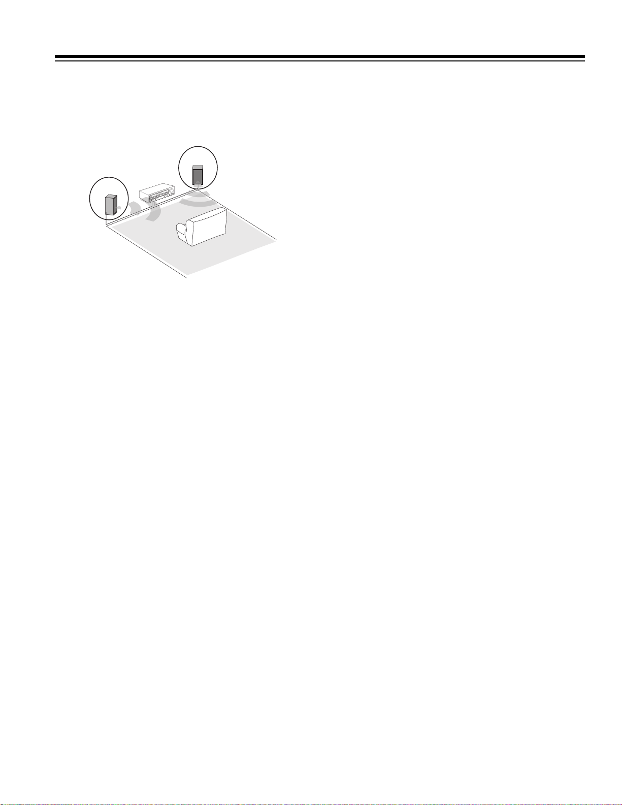
POSITIONING SPEAKERS
Speaker (not supplied) placement can make a noticeable
difference in your system’s sound. The guidelines in this
section will help you choose the best locations. After you use
your receiver for a while, you might want to try different
locations for your speakers.
Bass response depends largely on speaker location. For strong
bass, place the speakers in the corners of the room. If you want
even stronger bass, place the speakers directly on the floor. If
the bass is too strong, move the speakers slightly away from
the corners of the room, or raise them 6 to 18 inches off the
floor. You can buy speaker stands at your local RadioShack
store.
The distance between the speakers should be about the same as
the distance between the normal listening point and the point
halfway between the speakers. If you place the speakers too
close together, you reduce the stereo separation. If you place
them too far apart, you reduce the bass effect and create a
in the middle of the sound.
hole
terminals and the other pair to the B SPEAKERS
terminals.
• Optimus, and other high-quality speakers have colorcoded speaker terminals (red for positive polarity and
black for negative polarity). Use these color-coded
terminals as a guide to help you properly connect the
speakers to the receiver.
Use 16-gauge (or larger) speaker wire for all speaker
connections, and consider possible speaker locations before
you decide how much speaker wire you need.
Preparing the Speaker Wires
Speaker wire consists of two conductors (individual wires)
encased in insulation and is usually color-coded or marked
with a ridge along one side so you can identify each conductor.
Use these markings as a guide to help you properly connect the
speakers to your receiver.
Follow these steps to prepare the speaker wires.
1. Cut the speaker wires to the necessary length.
2. Separate the wires about 4 inches on each end.
3. Using a wire stripper, carefully strip about
insulation from the end of each conductor.
4. Twi st the end of each conductor to secure any loose wire
strands.
Caution: Twisting the end of each conductor helps pre v en t
a short circuit because stray speaker wire strands do not
touch other speaker terminals or any other receiver
terminals.
Connecting Speakers to the A and B Terminals
Note:
3
/4 inch of
Most speakers have a tweeter dispersion angle of about 60
degrees. Ideally, your listening position should be just inside
the overlap area of the tweeter dispersion. You can angle the
speakers toward you for better stereo effect.
CONNECTING SPEAKERS
Follow these guidelines when you select and connect speakers.
• Only connect speakers that are rated at between 8 and 16
ohms.
• Be sure you properly connect all speakers.
• Do not connect two pairs of speakers to a single set of
terminals (A or B) at the same time. When you use two
pairs of speakers, connect one pair to the A SPEAKERS
• Be sure you connect the receiver’s right and left positive
(+) and negative (–) terminals to the speaker’s
corresponding right and left positive (+) and negative (–)
terminals.
• Fully insert the speaker wires to ensure a good connection.
Leave extra wire at the back of the receiver so you do not
disconnect the wires when you move the receiver.
Follow these steps to connect each speaker (
right or left).
1. Press open the receiver’s positive (
speaker you want to conn ect and i n sert t he r i dged or colo rcoded conductor’s end into the small hole. Release the
lever to secure the conductor.
right or left or B
A
) red lever for the
+
5
Page 6

turntable’s ground wire to the receiver’s
terminal.
GND
screw
Connecting a CD Player
To connect a CD player to the receiver, connect the CD
player’s left and right output jacks to the receiver’s
jacks.
IN
L
and
Connecting a Cassette Deck
R CD
2. Press open the receiver’s negative (–) black lever for the
same speaker and insert the other conductor’s end into the
small hole. Release the lever to secure the conductor.
3. Connect the ridged or color-coded conductor’s loose end
to the speaker’s positive (+) terminal.
4. Connect the remaining loose conductor to the speaker’s
negative (–) terminal.
CONNECTING
PROGRAM SOURCES
Note: Use shielded audio cables with phono connectors for all
audio connections.
You can connect up to four external program sources to your
receiver.
You can connect a cassette deck to the
Connect the cassette deck’s output jacks to the
connect the cassette deck’s input jacks to the
TAPE MONITOR
PLA Y
REC
jacks.
jacks, and
jacks.
Connecting Another Audio Source
Connect the audio outputs of another aud i o so urce, s uch as the
audio from a laser disc player, TV, or VCR to the
AUX
jacks.
CONNECTING THE ANTENNAS
In many areas, the supplied indoor AM loop and FM antennas
provide satisfactory reception.
AM Antennas
Assemble the supplied AM antenna’s base by swinging the
base in the direction of the arrow and inserting the antenna’s
bottom tabs into the base’s slot. If the receiver is in a rack or o n
a shelf and there is no room for the AM loop antenna, use two
screws (not supplied) to mount the base on the wall or another
location as shown.
Connecting a Turntable
Connect a turntable with a magnetic cartridge on ly. Some older
turntables use a ceramic-type cartridge that does not work with
this system.
Connect the turntable’s left and right cables to the receiver’s
(left) and
6
(right)
R
PHONO IN
jacks. Then connect the
L
Page 7

Attach the antenna wires from the AM loop antenna to the AM
Inner Insulation
Outer Insulation
Shielding
Center Wire
and
GND
(ground)
ANTENNA
terminals.
For better FM reception, you can also use a rabbit-ear TV
antenna (for indoor use only) or an outdoor VHF TV antenna.
To connect the TV antenna to the receiver, you need a VHF/
UHF/FM splitter (not included). RadioShack stores carry a full
line of quality antennas and antenna connection accessories.
Place the antenna on a flat surface and rotate it for the best AM
reception.
Notes:
• Keep the AM loop antenna connected even when you use
another indoor antenna or an outdoor AM antenna.
• Ensure that the antenna does not touch the receiver or any
other meta l object.
• Do not place the antenna near a CD player, a personal
computer, or a TV set.
• If the wire between the AM loop antenna and your
receiver is too short, you can add extra wire, available at
your local RadioShack store.
You can also use an optional RadioShack shortwave antenna
kit (Cat. No. 278-758), which makes an excellent outdoor AM
antenna. Connect the outdoor AM antenna wire to the
receiver’s
AM ANTENNA
terminal as shown.
Warning:
To prevent injury, read and follow all cautions and
warnings that accompany the outdoor antenna.
For the best radio reception, use an outdoor antenna. Follow
these steps to connect an outdoor FM antenna to the receiver
using 75Ω coaxial cable.
Note: If your antenna has 300Ω twin-lead cable, connect it to
the
FM 300
Ω
ANTENNA
terminals.
1. Disconnect the supplied FM antenna from the receiver’s
FM 300
Ω
ANTENNA
2. With a stripping tool, remove about 1
terminal.
1
/2 inches of the 75Ω
cable’s outer insulation to expose the cable’s shielding.
3. Fold back the shielding from the inner insulation.
4. Remove about 1 inch of the inner insulation from around
the center wire.
FM Antennas
Note: For the best results, use 75-ohm coaxial cable to connect
an outdoor antenna to the receiver. Connect the supplied FM
antenna to the
extend it.
FM 300
Ω
ANTENNA
terminal as shown then
5. Pull the shielding to one side. Connect the center wire to
the receiver’s
FM 75Ω ANTENNA
terminal. Twist the
shielding to secure any loose wire strands, and connect it
to the
GND ANTENNA
Caution:
ANTENNA
The cable’s shielding should only touch the
terminal.
terminal.
Shielding
Center
Wire
FM
300ΩFM75Ω
AM
GND
GND
7
Page 8

Note: Grounding is not necessary for reception, but we
recommend it for better FM reception and to avoid damage
from lightning when you use an outdoor FM antenna. Use a
separate piece of thick polyvinyl insulated wire to connect the
GND ANTENNA
cold-water pipe.
Warning:
since sparks might ignite the gas.
terminal to an earth ground, such as a metal
Never connect a wire to a gas pipe for grounding
INSTALLING THE
REMOTE CONTROL’S BATTERIES
Cautions:
• Use only fresh batteries of the required size and
recommended type.
• Do not mix old and new batteries, different types of
batteries (standard, alkaline, or rechargeable), or
rechargeable batteries of different capacities.
• Dispose of old batteries promptly and properly. Do not
burn or bury them.
CONNECTING TO AC POWER
Warning: To prevent electric shock, do not use this polarized
plug with an extension cord, receptacle, or other outlet unless
you can fully insert the blades to prevent blade exposure.
Before you plug in the receiver’s power cord, double check all
other conn ections.
To power the receiver, plug the supplied power cord into a
standard AC outlet. The power cord ’s plug is polarized and fits
only one way.
• Always remove old or weak batteries. Batteries can leak
chemicals that can damage electronic circuits.
Your remote control requires two AA batteries (not included)
for power. For the best operation and longest life, we
recommend alkaline batteries, available at your local
RadioShack store.
1. To remove the battery compartment cover, push the
compartment’s tab in the direction of the arrow, then lift
off the cover.
2. Place two fresh AA batteries in the compartment as
indicated by the polarity symbols (+ and –) marked inside.
3. Replace the battery compartment cover.
The STAND BY indicator lights when the receiver is plugged
in but turned off.
Note: The receiver has a built-in circuit to protect it against
overheating or short circuits. If your receiver automatically
turns off (stand by mode), let it cool for several minutes. If the
receiver overheated, it should play normally when you turn it
back on. If there is a short circuit in your receiver, it will turn
off again when you turn on the receiver. If this happens, check
with your local RadioShack store for service.
Note: If the remote’s range is reduced, replace the batteries.
8
Page 9

OPERATION
Warning: To prevent possible hearing loss, turn
before you turn on the receiver or change the program
MIN
VOLUME
to
source. After you turn on the receiver or change the program
source, adjust
VOLUME
to a comfortable listening level.
You can use the supplied remote control by pointing it at the
receiver’s front panel and pressing the desired button(s). Many
buttons on the remote control work the same as buttons on the
receiver’s front panel. Use these buttons exactly as you would
use the corresponding buttons on the receiver.
Follow these steps to use the receiver.
1. Press
POWER
to turn on the receiver. It takes about 5
seconds to hear sound.
2. Select the speakers. An indicator lights next to the
or
to show which speakers are on.
B
If you connected speakers only to the
SPEAKERS
terminals, press
SPEAKERS A
on only thos e speakers. Do not press both
and
because doing so turns off all speakers even though
B
(or B)
A
(or B) to turn
SPEAKERS A
A
and/
both indicators are on.
If you connected speakers to both the
A
and
B SPEAKERS
terminals, you can:
•Press
SPEAKERS A
or B to turn on either pair of speak-
ers for a two-speaker effect.
7. When you finish using the receiver, press
POWER
it off.
USING THE SLEEP TIMER
The sleep timer lets you set the receiver to play for up to 90
minutes, then automatically turns off.
1. To set the timer, turn on the receiver then press
the remote control. The display dims and shows
90 SLEEP
.
2. To set the sleep timer for less than 90 minutes, repeatedly
SLEEP
to decrease the time by 10 minutes for each
press
press of the button. Once you select the time, the receiver
displays the program source. (
SLEEP
stays on the display
in small letters until automatic shut-off.)
3. To briefly see the time remaining, press
SLEEP
TUNING THE RADIO
Your receiver has four types of electronic tuning — manual,
automatic, direct, and memory.
Note: For weak signals, we recommend manual tuning.
to turn
SLEEP
SLEEP
once.
on
•Press
SPEAKERS A
and B to turn on both pairs of
speakers for a four-speaker effect.
Press
SPEAKERS A
and/or B to turn off all speakers so
you can listen privately with headphones (see “Using
Headphones” on Page 11).
3. Select a program source.
To tune to a radio station, see “Direct Tuning (Remote
Control Only)” on Page 10.
To listen to signals from the component connected to the
TAPE MONITOR
appears.
MON
jacks, press
TAPE MONITOR
so
TAPE
To list en to a source other than the one connected to the
AUX
appears).
jacks, press
TAPE MONITOR
CD, PHONO
clockwise to increase the volume or
TAPE MONITOR
disappears. Then press
MON
PHONO
4. Turn
, or
VOLUME
counterclockwise to decrease it. Or , you can us e
, or
so
(CD,
AUX
VOLUME
TAPE
and on the remote control.
5. To adjust the tone, turn
. To increase the high and low ranges of sound at low
–
volume, press
LOUDNESS
LOUDNESS
again.)
BASS
and
TREBLE
toward + or
. (To turn off this feature, press
6. To adjust the balance of sound between the left and right
speakers, see “Adjusting Balance” on Page 11.
Manual and Automatic Tuning
Follow these steps to manually or automatically tune to the
stations.
1. Press
control) to select the desired band. The receiver tunes to
and displays the frequency last selected in that band.
2. If CH appears on the right side of the di sp l ay, press
to change the receiver to manual-tuning mode.
briefly appears.
3. To manually select the next higher or lower frequency,
press
button to rapidly scan through the frequencies; release the
button to stop scanning.
To automatically search for the next higher or lower
station, briefly hold down
rapidly scanning through the frequencies. The receiver
searches up or down the band, s toppi n g on the ne xt st r ong
station.
Notes:
•
•
or AM on the front panel (or on the remote
FM
TUNING UP
appears when the received signal is strong.
TUNED
STEREO
or
appears when the received FM broadcasts are
once. Or, hold down the
DOWN
TUNING UP
in stereo.
or
MANUAL
DOWN
MODE
to begin
9
Page 10

• If you press
range or
TUNING DOWN
TUNING UP
at the top of the frequency
at the bottom of the frequency
range, the frequency at the opposite end of the range
appears.
Repeat these steps to automatically store stations in the other
band.
Manually Storing a Station
Direct Tuning (Remote Control Only)
Follow these steps to directly enter a frequency.
1. Press
or AM on the front panel (or on the remote
FM
control) to select the desired band. The receiver tunes to
and displays the frequency last selected in that band.
2. Press
DIRECT TUNING
scrolls by , follo wed by AM
IN
– –
–
.
for FM. The first – flashes.
MHz
on the remote control.
– – – –
for AM or FM
kHz
DIRECT
– –
3. Enter the desired frequency using the remote control’s
number buttons.
Notes:
• If you press
automatically appears. If you also press the zero, the
10
frequency that appears would be
to enter a FM frequency, such as 103.5,
1
100.30
.
• The last zero always appears automatically in both FM
and AM frequencies.
• If you do not press a key within 5 seconds, the receiver
exits direct tuning. Start over at Step 2.
MEMORY TUNING
Memory tuning lets you instantly tune to a stored frequency.
You can store up to 30 AM and 30 FM frequencies in the
receiver’s memory. The receiver automatically stores the first
30 stations found in the selected band into the memory. You
can also manually store a station into memory.
When the receiver automatically stores stations, some of them
might not be your favorites. Or, the 30 -chan nel memor y mi gh t
have filled up before the receiver reached your favorite station
at the high end of the frequency range. Follow these steps to
manually replace a station in memory.
1. Press
control) to select the desired band. The receiver tunes to
and displays the frequency last selected in that band.
or AM on the front panel (or on the remote
FM
2. If CH appears on the right side of th e di sp la y, press
to change the receiver to manual-tuning mode.
briefly appears.
3. Use either automatic or manual tuning to find the desired
station.
4. Press
5. While
MEMORY
MEMORY
.
MEMORY
flashes on the display.
flashes, press
TUNING UP
the desired memory channel number appears.
6. Press
MEMORY
again to store the station immediately . Or,
wait about 5 seconds and the station is automatically
stored in the selected channel.
Notes:
• If you store a frequency in a memory that already con tains
a frequency, you replace the previous frequency.
• If your receiv er is disconn ected from AC power for several
days, it loses all the stored frequencies.
Tuning to a Station in Memory
or
MODE
MANUAL
DOWN
until
Automatically Storing Stations
1. Press FM or AM on the front panel (or on the remote
control) to select the desired band. The receiver tunes to
and displays the frequency last selected in that band.
2. Hold down
MEMORY
and CH appear while the receiver steps through the
frequencies, beginning with the low end (87.5 MHz for
FM or 530 kHz for AM).
3. When the receiver finds a station, it stores in the first
memory channel, the CH number increments, and the
receiver look s for the ne xt station . When the recei v er f i nds
the thirtieth station or when it reaches the high end of the
frequency range,
tunes to the lowest frequency station in the band.
10
for more than 2 seconds.
MEMORY
disappears and the receiver
MEMORY
1. Press FM or AM on the front panel (or on the remote
control) to select the desired band. The receiver tunes to
and displays the frequency last selected in that band.
2. If CH does not appear on the right side of the display, press
to change the receiver to memory-tuning mode.
MODE
PRESET
3. Press
briefly appears.
TUNING UP
or
DOWN
(or
PRESET CALL
and
on the remote control) to tune to the next higher or
lower station stored in memory.
Or, press
PRESET SCAN
to scan through the stations in
memory. The receiver tunes to each station for about 5
seconds. When you hear the station you want to listen to,
press
PRESET SCAN
again.
You can also tune to a station in memory by using the
remote control’s number buttons to enter the channel
number. For single-digit channels, enter
example, enter
for Channel 6).
06
first (for
0
Page 11

Notes:
• To improve the reception of weak FM stations, press
. This reduces signal noise, but you hear monaural
MODE
instead of stereo sound.
• For stations with a weak signal, we recommend manual
tuning.
FM
CASSETTE DECK FEATURES
You can connect a cassette deck to the receiver. Selecting
TAPE MONITOR
deck you connected to the receiver’s
Using the Tape Monitor
Button
lets you hear the playback from the cassette
TAPE MONITOR
jacks.
ADJUSTING BALANCE
The
BALANCE
between the left and right speakers. If you properly position the
speakers and your listening area is centered between them, the
center control setting is usually best (see “Positioning
Speakers” on Page 5).
For an unusual speaker placement, press
band or select any source and play a monaural audio source.
Turn
BALANCE
each speaker when you are in the listening area.
control lets you adjust the sound balance
to select the AM
AM
until you hear the sound coming equally from
MUTING THE RECEIVER
To temporarily mute the sound, press
control. The MUTE indicator on the receiver flashes. Press
MUTING
turns off.
again to restore the audio level. The MUTE indicator
MUTING
on the remote
USING HEADPHONES
To listen with headphones (not supplied), insert the
headphones’
PHONES
headphones without disturbing others, press
and/or
Listening Safely
1
/4-inch plug into the receiver’s front panel
jack. To silence the speakers and listen with
SPEAKERS A
so both indicators are off.
B
Press
T APE MONITOR
program source you selected. You can hear the playback or
monitor a recording from the cassette deck you connected to
the receiver’s
The
TAPE MONITOR REC
previously selected sound source after you press
MONITOR
To return to the previous source, press
so
TAPE MON
Note:
If you press
neither playing nor recording, the receiver mutes the current
audio source. To hear the audio source, p ress
so
TAPE MON
TAPE MONITOR
.
disappears.
disappears.
.
TAPE MON
jacks.
jacks continue to output the
TAPE MONITOR
appears, along with the last
T APE
TAPE MONITOR
when that cassette deck is
T APE MO NIT OR
again
Recording a
Program Source
The receiver sends the audio of the program source you
select—
PHONO
control does not affect the level of the signal going to the tape
decks.
When you record a program source using the cassette deck,
you hear the program source’s signal immediately after you
record it onto the tape, if the cassette deck you connected has a
three-head monitor function. (Be sure to read the owner’s
manual for your cassette deck.)
TAPE MONITOR, AUX, CD, FM/AM
—to the
TAPE MONITOR REC
(tuner), or
jacks. The
VOLUME
To protect your hearing, note the following when using
headphones.
• Set the volume to its lowest setting before you begin
listening. After yo u begin listening, adj us t th e volume to a
comfortable level.
• Do not listen at extremely high volume levels. Extended
high-volume listening can lead to permanent hearing loss.
• Once you set the volume, do not increase it. Over time,
your ears adapt to the volume level, so a volume level that
does not cause discomfort might still damage your
hearing.
USING THE RESET BUTTON
If the receiver is subjected to a strong magnetic field or an
electric shock, it might operate erratically. If this happens, turn
off the receiver and press the rear panel
straightene d paperclip or other point ed object.
Caution: Pressing
receiver’s memory.
RESET
clears everything stored in the
RESET
button with a
11
Page 12

TROUBLESHOOTING
If the receiver is not working as it should, the following suggestions might help. If you follow the suggestions in this chart and the
receiver still does not work properly, contact your local RadioShack store for assistance.
Problem Cause Suggestion
Power does not turn on. Power cord is disconnected. Plug in the power cord.
No sound. Incorrect connections. Check and correct the connections.
The mute function is activated. Press
MUTING
The volume is turned down. Turn up the volume.
Speaker wires are disconnected. Connect the speaker wires.
Neither set of speakers is selected. Press
Both
SPEAKERS A
and B are selected
when only one set of speakers is
SPEAKERS A
Press
SPEAKERS A
speakers that are not connected.
connected.
TAPE MONITOR
is selected. Press
TAPE MONITOR
turns off.
Sound from only one speaker. One of the speaker wires or the input cord
Check all connections.
is disconnected.
BALANCE
is set too far to one side. Set
BALANCE
High noise level. Station not correctly tuned. Adjust tuning.
Antenna not connected. Connect the antenna.
FM antenna still coiled or is not pointing
in the correct direction.
AM loop antenna not pointing in the
Stretch both ends of the antenna taut and
reposition the antenna.
Adjust the AM loop antenna.
correct direction.
.
or
B.
or B to turn off the
so
TAPE MON
to the center position.
Automatic tuning does not stop when
Noise is coming from another electrical
appliance.
Stations are too weak. Us e a better antenna.
Try using an AC line noise filter to
reduce the noise.
searching for stations.
Remote control does not work. Batteries are weak or missing. Install fresh batteries.
Poor angle or too great a distance from
the remote sensor window.
There is an obstacle between you and the
remote sensor window.
A fluorescent light is shining on the
Use the remote control within the
effective range.
Change your position or remove the
obstacle.
Turn off the light.
remote sensor window.
12
Page 13

CARE AND MAINTENANCE
To enjoy your RCA STA-3850 Stereo Receiver for a long
time:
• Keep the receiver dry. If it gets wet, wipe it dry
immediately.
• Use and store the receiver only in normal temperature
environments.
• Handle the receiver gently and carefully. Don’t drop it.
• Keep the receiver away from dust and dirt.
• Wipe the receiver with a damp cloth occasionally to keep
it looking new.
Modifying or tampering with the receiver’s internal
components can cause a malfunction and invalidate its
warranty.
This receiver has been manufactured to the specifications of
RadioShack and is covered by a limited warranty from
RadioShack. If your receiver is not operating as it should, take
it to your local RadioShack store or call 1-800-THE-SHACK
for assistance.
THE FCC WANTS YOU TO KNOW
Your receiver might cause radio or TV interference even when
it is operating properly. To determine whether your receiver is
causing the interference, turn off your receiver. If the
interference goes away, your receiver is causing it. Try to
eliminate the interference by:
• Moving your radio or TV away from the receiver
• Connecting your receiver to an outlet that is on a different
electrical circuit from the radio or TV
• Contacting your local RadioShack store for help
If you cannot eliminate the interference, the FCC requires that
you stop using your receiver.
13
Page 14

SPECIFICATIONS
Amplifier
Power Output ................................................................................................................................. 50 Watts per Channel into 8 Ohms
From 40 to 20,000 Hz,
With No More than 0.5% Total Harmonic Distortion
Measured Pursuant to the Federal Tr ade Commission’s
Trade Regulation Rule on Amplifier Output Power Claims
Input Sensitivity/Impedance
Phono ....................................................................................................................................................................... 2.5 mV/47 kohms
CD, AUX, TAPE MONITOR ................................................................................................................................. 200 mV/47 kohms
Signal-to-Noise Ratio (IHF, Short-Circuited, A Network)
Phono .......................................................................................................................................................................................... 72 dB
CD, AUX, TAPE MONITOR ..................................................................................................................................................... 95 dB
FM Tuner
Frequency Range ...................................................................................................................................................... 87.5 to 108 MHz
Usable Sensitivity ............................................................................................................................................. Mono: 15 µV/m, EMF
Signal-to-Noise Ratio
Mono ........................................................................................................................................................................................... 68 dB
Stereo .......................................................................................................................................................................................... 63 dB
Distortion ............................................................................................................................................................ Stereo: 0.5% (1 kHz)
Alternate Channel Selectivity .................................................................................................................................... 45 dB (400 kHz)
Stereo Separation ................................................................................................... ........................................................ 35 dB (1 kHz)
AM Tuner
Frequency Range ....................................................................................................................................................... 530 to 1720 kHz
Sensitivity (IHF, Loop Antenna) ......................................................................................................................................... 500 µV/m
Selectivity ................................................................................................................................................................................... 25 dB
Signal-to-Noise Ratio ................................................................................................................................................................. 35 dB
General
Power Requirements ............................................................................................................................................ 120 Volts AC, 60 Hz
Power Consumption ............................................................................................................................................................. 120 Watts
Dimensions (HWD) ................................................................................................................................... 5
Weight ............................................................................................................................................................................. 14 lb (6.3 kg)
Specifications are typical; individual units might vary. Specifications are subject to change and improvement without notice.
1
/8 × 169/16 × 121/4 Inches
(130 × 420 × 310 mm)
14
Page 15

NOTES
15
Page 16

Limited Two-Year Warranty
This product is warrante d by RadioShack aga inst manufacturi ng defects in mate rial and workma nship under normal use for two (2) years from the date of purchase from RadioShack companyowned stores and authorized RadioShack franchisees and dealers. EXCEPT AS PROVIDED
HEREIN, RadioShack MAKES NO EXPRESS WARRANTIES AND ANY IMPLIED WARRANTIES,
INCLUDING THOSE OF MERCHANTABILITY AND FITNESS FOR A PARTICULAR PURPOSE,
ARE LIMITED IN DURATION TO THE DURATION OF THE WRITTEN LIMITED WARRANTIES
CONTAINED HEREIN. EXCEPT AS PROVIDED HEREIN, RadioShack SHALL HAVE NO LIABILITY OR RESPONSIBILITY TO CUSTOMER OR ANY OTHER PERSON OR ENTITY WITH RESPECT TO ANY LIABILITY, LOSS OR DAMAGE CAUSED DIRECTLY OR INDIRECTLY BY USE
OR PERFORMANCE OF THE PRODUCT OR ARISING OUT OF ANY BREACH OF THIS WARRANTY, INCLUDING, BUT NOT LIMITED TO, ANY DAMAGES RESULTING FROM INCONVENIENCE, LOSS OF TIME, DATA, PROPERTY, REVENUE, OR PROFIT OR ANY INDIRECT,
SPECIAL, INCIDENTA L, OR CONSEQUENT IAL DAMAGES, EVEN I F RadioShack HAS BEEN ADVISED OF THE POSSIBILITY OF SUCH DAMAGES.
Some states do not allow the limitations on how long an implied warranty lasts or the exclusion of incidental or consequential damages, so the above limitations or exclusions may not apply to you.
In the event of a pro duct defect duri ng the warranty period, take the p roduct and the R adioShack
sales receipt as proof of purchase date to any RadioShack store. RadioShack will, at its option, unless otherwise provid ed by law: (a) c orr ect the de fect by product repair with ou t ch arg e f or par ts a nd
labor; (b) replace the product w ith one of the same or similar design; or (c) refund the purch ase
price. All replace d parts a nd produ cts, and p roducts on which a refund is made, become th e property of RadioShack. New or recond itioned parts and products may be used in the per formance of
warranty service. Re paired or repl aced parts and p roducts are warr anted for the r emainder of the
original warranty period. You will be charged for repair or replacement of the product made after the
expiration of the warranty period.
This warranty does not cover: (a) damage or failure caused by or attributable to acts of God, abuse,
accident, misuse, improper or abnorm al usag e, failure to fo llow in struction s, improp er inst allatio n or
maintenance, alteratio n, lightning or other incidence of excess voltage or cur rent; (b) any repairs
other than those provided by a RadioShack Authorized Service Facility; (c) consumables such as
fuses or batteries; (d) cosmetic d amage; (e) transporta tion, shipp ing or insuran ce costs; or (f) costs
of product removal, installation, set-up service adjustment or reinstallation.
This warranty give s you specific le gal rights, and you may also h ave other right s which vary fr om
state to state.
RadioShack Customer Relations, 200 Taylor Street, 6th Floor, Fort Worth, TX 76102
We Service What We Sell
04/99
RadioShack
A Division of Tandy Corporation
Fort Worth, Texas 76102
31-5002
08A99 Printed in China
 Loading...