

Page 1
SpeedTouch™
(Wireless) Business DSL Router
IPQoS Configuration Guide
Release R5.3.0
SpeedTouch™608WL and
SpeedTouch™620 only
Page 2

Page 3

SpeedTouch™
IPQoS Configuration Guide
R5.3.0
Page 4

Copyright
Copyright ©1999-2005 THOMSON. All rights reserved.
Passing on, and copying of this document, use and communication of its contents is not permitted without written authorization
from THOMSON. The content of this document is furnished for informational use only, may be subject to change without notice,
and should not be construed as a commitment by THOMSON. THOMSON assumes no responsibility or liability for any errors or
inaccuracies that may appear in this document.
Thomson Telecom Belgium
Prins Boudewijnlaan, 47
B-2650 Edegem
Belgium
www.speedtouch.com
Trademarks
The following trademarks are used in this document:
SpeedTouch™ is a trademark of THOMSON.
Microsoft®, MS-DOS®, Windows® and Windows NT® are either registered trademarks or trademarks of Microsoft Corpora-
tion in the United States and/or other countries.
UNIX® is a registered trademark of UNIX System Laboratories, Incorporated.
Apple® and Mac OS® are registered trademarks of Apple Computer, Incorporated, registered in the United States and other
countries.
Adobe, the Adobe logo, Acrobat and Acrobat Reader are trademarks or registered trademarks of Adobe Systems, Incorpo-
rated, registered in the United States and/or other countries.
Netscape® and Netscape Navigator® are registered trademarks of Netscape Communications Corporation.
Ethernet™ is a trademark of Xerox Corporation.
UPnP™ is a certification mark of the UPnP™ Implementers Corporation.
Wi-Fi® and the Wi-Fi logo are registered trademarks of the Wi-Fi Alliance. "Wi-Fi CERTIFIED", "Wi-Fi ZONE", "Wi-Fi Alli-
ance", their respective logos and "Wi-Fi Protected Access" are trademarks of the Wi-Fi Alliance.
Other products may be trademarks or registered trademarks of their respective manufacturers.
Document Information
Status: v0.5 (March 2005)
Reference: E-NIT-CTC-20041213-0013
Short Title: IPQoS Configuration Guide STBUS R5.3.0
Page 5

Contents
Contents
About this IPQoS Configuration Guide...................... 7
1 Document scope ........................................................... 9
2 Introduction .................................................................11
2.1 What is Quality of Service? .......................................................... 12
2.2 Relative versus Guaranteed QoS.................................................. 14
3 Basic QoS Concepts.................................................... 15
3.1 Precedence and TOS .................................................................... 16
3.2 Differentiated Services ................................................................ 18
3.3 Classification and conditioning principles................................... 20
3.4 Differentiated Services Code Point (DSCP) ................................. 22
4 IP QoS Framework Overview..................................... 25
4.1 Main Framework Components ..................................................... 26
E-NIT-CTC-20041213-0013 v0.5
4.2 Resource Management ................................................................. 27
5 Packet Classification and Labelling ........................... 29
3
Page 6

Contents
5.1 Classification ............................................................................... 30
5.1.1 Order of classification rules............................................................................ 31
5.2 Labels ........................................................................................... 33
5.2.1 Label parameters explained............................................................................ 35
5.2.2 Using TOS, DSCP or Precedence .................................................................... 38
5.2.3 Forwarding parameters.................................................................................. 40
5.3 Rules ............................................................................................ 42
5.3.1 Rules parameters explained............................................................................ 43
5.3.2 Rule debug commands .................................................................................. 47
5.4 Chains .......................................................................................... 49
5.4.1 Define a relation between chains .................................................................... 51
5.5 Expressions .................................................................................. 52
5.5.1 Expression parameters .................................................................................. 53
6 Meters, queues and IPQoS......................................... 59
6.1 Meters and queues ....................................................................... 60
6.2 The IPQoS command group ......................................................... 61
6.3 EF timers ...................................................................................... 63
6.4 Meter command group ................................................................. 67
6.4.1 Meter config command ................................................................................. 68
6.4.2 Packet flow ................................................................................................. 74
6.5 Queue command group ................................................................ 75
6.5.1 Queue config parameters explained................................................................. 76
6.6 IPQoS Command group ................................................................ 81
6.6.1 Ipqos config parameters explained.................................................................. 82
7 Scenario 1: Residential user....................................... 85
4
E-NIT-CTC-20041213-0013 v0.5
Page 7

Contents
7.1 Configuring labels and rules for VoIP. ......................................... 86
7.2 Configuring labels and rules for DSCP. ....................................... 90
7.3 Configuring labels and rules for Interactive traffic. .................... 92
7.4 IPQoS configuration..................................................................... 95
8 Scenario 2: Business user with TOS marking. ......... 97
8.1 Labels ........................................................................................... 99
8.2 Rules. ......................................................................................... 103
8.3 IPQoS per PVC ........................................................................... 112
9 Scenario 3: Metering................................................. 115
E-NIT-CTC-20041213-0013 v0.5
5
Page 8

Contents
Page 9
About this IPQoS Configuration Guide
About this IPQoS Configuration Guide
In this configuration
guide
Used Symbols
Applicability and
terminology
This routing configuration guide explains how routes can/must be used in
SpeedTouch™ R5.3 products. To explain the use of routes, a distinction is made
between standard IP forwarding and packet-based classification.
All examples start from a clean SpeedTouch™ configuration.
A note provides additional information about a topic.
A tip provides an alternative method or short-cut to perform an action.
A caution warns you about potential problems or specific precautions that
!
need to be taken.
This IPQoS Configuration Guide is applicable to:
SpeedTouch™ 516/536/546/576 Multi-user ADSL gateways.
SpeedTouch™ 585 Residential DSL router.
SpeedTouch™ 620 Business DSL router.
SpeedTouch™ 605 Business Multi-user ADSL gateway.
SpeedTouch™ 608 Business DSL router.
Generally, all these SpeedTouch™620 products will be referred to as SpeedTouch™ in
this IPQoS Configuration Guide, unless a specific device is mentioned.
On some products the expert web pages are not available, almost the same
functionality is offered through CLI configuration.
Typographical
Conventions
Documentation and
software updates
E-NIT-CTC-20041213-0013 v0.5
When we display interactive input and output we’ll show our typed input in a bold
font and the computer output
Comments are added in italics.
Example:
=>language list
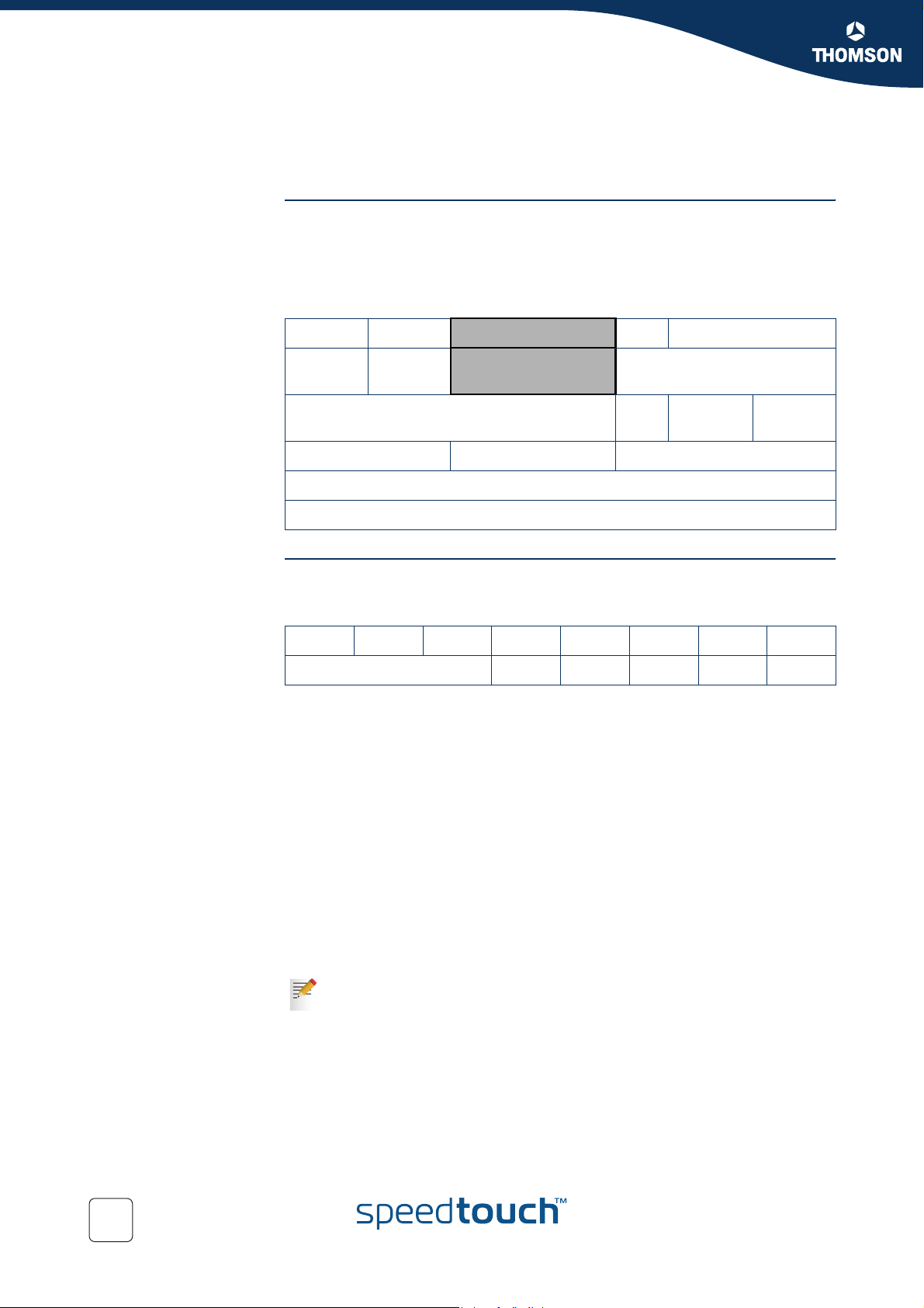
CODE LANGUAGE VERSION FILENAME
en* english 4.2.0.1 <system>
Bold is also used in the output to emphasize a specific section.
THOMSON continuously develops new solutions, but is also committed to improve
its existing products.
For more information on THOMSON's latest technological innovations, documents
and software releases, visit us at:
like this.
Only one language is available
www.speedtouch.com
7
Page 10

About this IPQoS Configuration Guide
8
E-NIT-CTC-20041213-0013 v0.5
Page 11

Document scope
1 Document scope
Introduction The SpeedTouch™ Release 5.3.0 has a strong Quality of Service (QoS) base that
allows classification and forwarding of data to a single or multiple ATM VPI/VCIs
with each a set of ATMQoS parameters. IP Quality of Service is an extension to this
QoS framework. This configuration guide presents:
An introduction on IPQoS
An overview of the IPQoS framework
An overview of the labels, rules and expressions
An overview of the queue, meters and IPQoS commands
Some IPQoS application examples and how to configure them
A “Residential Scenario” using a single LAN segment with different
services.
A “Business Scenario” using multiple LAN segment with different services
and priorities.
A “Rate Limiting Scenario” using interface based rate limiting.
Chapter 1
E-NIT-CTC-20041213-0013 v0.5
9
Page 12

Chapter 1
Document scope
Page 13

2Introduction
Introduction This chapter gives a general description and use of Quality of Service.
In this chapter
Topi c Pag e
2.1 What is Quality of Service? 12
2.2 Relative versus Guaranteed QoS 14
Chapter 2
Introduction
E-NIT-CTC-20041213-0013 v0.5
11
Page 14

Chapter 2
Introduction
2.1 What is Quality of Service?
Definition Quality of Service is the ability for an application to obtain the network service it
requires for successful operation.
Nowadays the total amount of data traffic increases, while new types of data
emerge, like: voice data, video data, audio data. These new types of data pose new
requirements for data transport, e.g. low latency, low data loss… To meet these
requirements, the entire network must ensure them via a connection service
guarantee. Such a connection service guarantee can both be applied to connectionoriented networks (connection based) and to packet-oriented networks (data-stream
or data type based).
Quality of Service allows specifying a connection service guarantee via a set of
connection parameters. Throughout the network, this set of connection parameters
will be used to handle the connection data in a way to achieve the connection
service guarantee. This handling includes reserving bandwidth, priority based
queuing, scheduling, modifying data characteristics, …
Examples of connection parameters include the maximum amount of bandwidth that
may be used, the guaranteed amount of bandwidth that will always be available, the
maximum delay the data can experience throughout the network, a priority
indication,…
Misunderstandings A common misunderstanding about QoS is that QoS is about gaining a superior level
of network service for particular individuals.
The example below illustrates this.
The best illustration of why it is pointless to give enhanced network service to
particular individuals is shown by video-conferencing. Imagine John: he sees a
horrible quality image of the other video conference participant; but the other
participant sees John’s face perfectly. This is obviously not the desired result.
For John to also see a high-quality image, all participants in the video conference
need appropriate network service, not only John.
IP QoS provides such service. With IP QoS voice and/or video traffic can get a higher
priority then data traffic. This way good voice and video quality is guaranteed.
Note that QoS is no solution for overloaded networks, it only helps to shape
!
bursty peaks on the network. (See Bandwidth versus QoS )
12
E-NIT-CTC-20041213-0013 v0.5
Page 15

Bandwidth versus QoS Quality of Service is really best noticed when the Best Effort service encounters
congestion. So a common question is "why not provide more bandwidth, use Best
Effort, and get rid of complicated QoS architectures?"
There are four answers:
First of all, it is less economic to use more bandwidth than to use QoS. Many
congestion problems can be resolved by using QoS.
The second reason is, Denial of Service (DoS) attacks can always fill links. Even
a 10Gbps link can be flooded by ten compromised gigabit ethernet hosts. QoS
allows Voice traffic to work perfectly even at the peak of a DoS incident.
The third reason is, a scavenger service (also known as a "worst effort" or "less
than best effort" service) gives Best Effort traffic such as web browsing priority
over traffic such as large downloads.
Last but not least, we can use quality of service to ameliorate the effect of TCP
unfriendly traffic, such as unauthenticated video (UDP). This amelioration can
prevent congestion collapse of Best Effort traffic due to excessive video load.
Using QoS for this function is in no way as satisfactory as modifying video
stream and video multicast protocols to become TCP friendly. But using QoS
does ameliorate the worst effect of these TCP unfriendly protocols.
Chapter 2
Introduction
Bandwidth does improve the latency for data, but may still require QoS for
congestion management and “guaranteed QoS”.
E-NIT-CTC-20041213-0013 v0.5
13
Page 16

Chapter 2
Introduction
2.2 Relative versus Guaranteed QoS
Typ es of QoS There are two different approaches to achieve QoS:
Guaranteed QoS:
Measurable connection parameters are specified for certain data or for a
connection, for example a guaranteed amount of bandwidth or delay across the
network. This allows for an exact specification and measurement of the Quality
of Service of data or a connection.
Examples of “guaranteed QoS” are Integrated Services (IntServ) and ATM QoS
like VBR and CBR connections.
Relative QoS (also referred to as differentiated QoS):
A priority indication is given as connection parameter to certain data or to a
connection, so that this data or connection will be handled with precedence
over data or connections with less priority. Obviously this approach guarantees
no specified bandwidth or latency, but it is the easiest approach to achieve
some level of QoS for high priority data.
Examples of “relative QoS” are Differentiated Services (DiffServ, DS) and
Ethernet VLAN user priority indication.
The guaranteed QoS approach is slightly more complicated than Relative
QoS because the connection parameters have to be specified and may be
verified throughout the entire network.
In case of relative QoS, data is often specified to belong to a certain Class of
Service (CoS) instead of QoS. Treatment and priority of data throughout the
network is configured for each supported CoS.
14
E-NIT-CTC-20041213-0013 v0.5
Page 17

3 Basic QoS Concepts
Introduction This chapter provides a brief explanation about:
Basic concepts of Quality of Service in general.
Precedence and TOS in general
The Differentiated Services architecture in detail
In this chapter
Topi c Pag e
3.1 Precedence and TOS 16
3.2 Differentiated Services 18
3.3 Classification and conditioning principles 20
Chapter 3
Basic QoS Concepts
3.4 Differentiated Services Code Point (DSCP) 22
E-NIT-CTC-20041213-0013 v0.5
15
Page 18
Chapter 3
Basic QoS Concepts
3.1 Precedence and TOS
Introduction There are two generations of quality of service architectures in the Internet Protocol.
The interpretation of the Type of Service Octet in the Internet Protocol header varies
between these two generations.
The figure below shows the Internet Protocol header.
The Type of Service Octet is the second 8-bit octet of the Internet Protocol header.
04
Version Header
Length
Identification DM
Time to Live Protocol Header Chuckles
Type of Service Total Length
Source Address
Destination Address
First generation Precedence and Type of Service bits.
The initial definition of the Type of Service Octet looked like this:
01234567
Precedence D T R C
Most Precedence descriptions are obscure: they relate to message handling priorities
of US military communications in the 1960s. The essence is that higher values of
Precedence lead to higher levels of network service.
To prevent high link utilisation causing routing traffic to be lost, it is traditional to use
Precedence = 7 for interior routing protocols, such as OSPF and RIP and to use
Precedence = 6 for exterior routing protocols such as BGP.
The D type of service bit can be a value of 0 to request normal delay, a value of 1 to
request a low delay service.
The T type of service bit can be a value of 0 to request normal throughput, a value of
1 to request a high throughput service.
The R type of service bit can be a value of 0 to request normal reliability, a value of 1
to request a high reliability service.
The C type of service bit can be a value of 0 to request normal costs, a value of 1 to
request a low cost service.
The D,T,R and C type of service bit is defined in RFC791 (Internet Protocol)
81631
OFF
16
E-NIT-CTC-20041213-0013 v0.5
Page 19

Precedence values The table below gives the precedence values:
Precedence Purpose
0Routine
1Priority
2 Immediate
3Flash
4Flash Override
5CRITIC/ECP
6 Internetwork Control
7 Network Control
Chapter 3
Basic QoS Concepts
Note that IP Precedence is obsolete and is only implemented to provide
backwards compatibility.
Second generation The Differentiated Service Code Point is a selector for router's per-hop behaviours.
01234567
Differentiated Service Code Point ECT CE
The fields ECT and CE are spare bits in the IP header used by Explicit Congestion
Notification (RFC3168).
As can be seen, the DSCP field supersedes the old Precedence field. So the values of
DSCP provide limited backwards compatibility with Precedence.
This leads to notions of "class", each class being the group of DSCPs with the same
Precedence value. Values within a class would offer similar network services but
with slight differences (used to create different levels of service such as "gold",
"silver" and "bronze").
E-NIT-CTC-20041213-0013 v0.5
17
Page 20

Chapter 3
Basic QoS Concepts
3.2 Differentiated Services
Introduction Differentiated Services (DiffServ) is an architecture which allows service providers to
offer different kinds of services to different customers and their traffic streams.
Differentiated Services is a framework for scalable service discrimination and allows
an approach to modular IPQoS objectives for the needs of various types of
applications.
The premise to DiffServ networks is that routers within the core of the network are
capable to forward the packets of different traffic streams in different Per-Hop
Behaviours (PHB). The PHB for the packets is indicated by a Differentiated Services
Codepoint (DSCP) in the IP header. The DiffServ architecture does not use any
signalling between the routers but all the forwarding behaviour is defined by using
the DSCP.
Terminology Before we continue we will explain the abbreviations used in this section.
Behaviour Aggregate (BA):
Is a collection of packets with the same Differentiated Services codepoint, thus
receiving the same PHB, crossing a DiffServ node in a particular direction.
Differentiated Services CodePoint (DSCP):
Is the value in the IP header in the DS field, used to select the PHB.
Per-Hop Behaviour (PHB):
Is the forwarding behaviour for the packet applied at DiffServ compliant nodes
to a DiffServ BA.
Service Level Specification (SLS):
Is a set of parameters and their values which together define the service offered
to a traffic stream by a DiffServ domain.
Traffic Conditioning Specification (TCS):
Is a set of parameters and their values which together specify a set of classifier
rules.
18
E-NIT-CTC-20041213-0013 v0.5
Page 21
Chapter 3
e
Basic QoS Concepts
Differentiated Services
domain
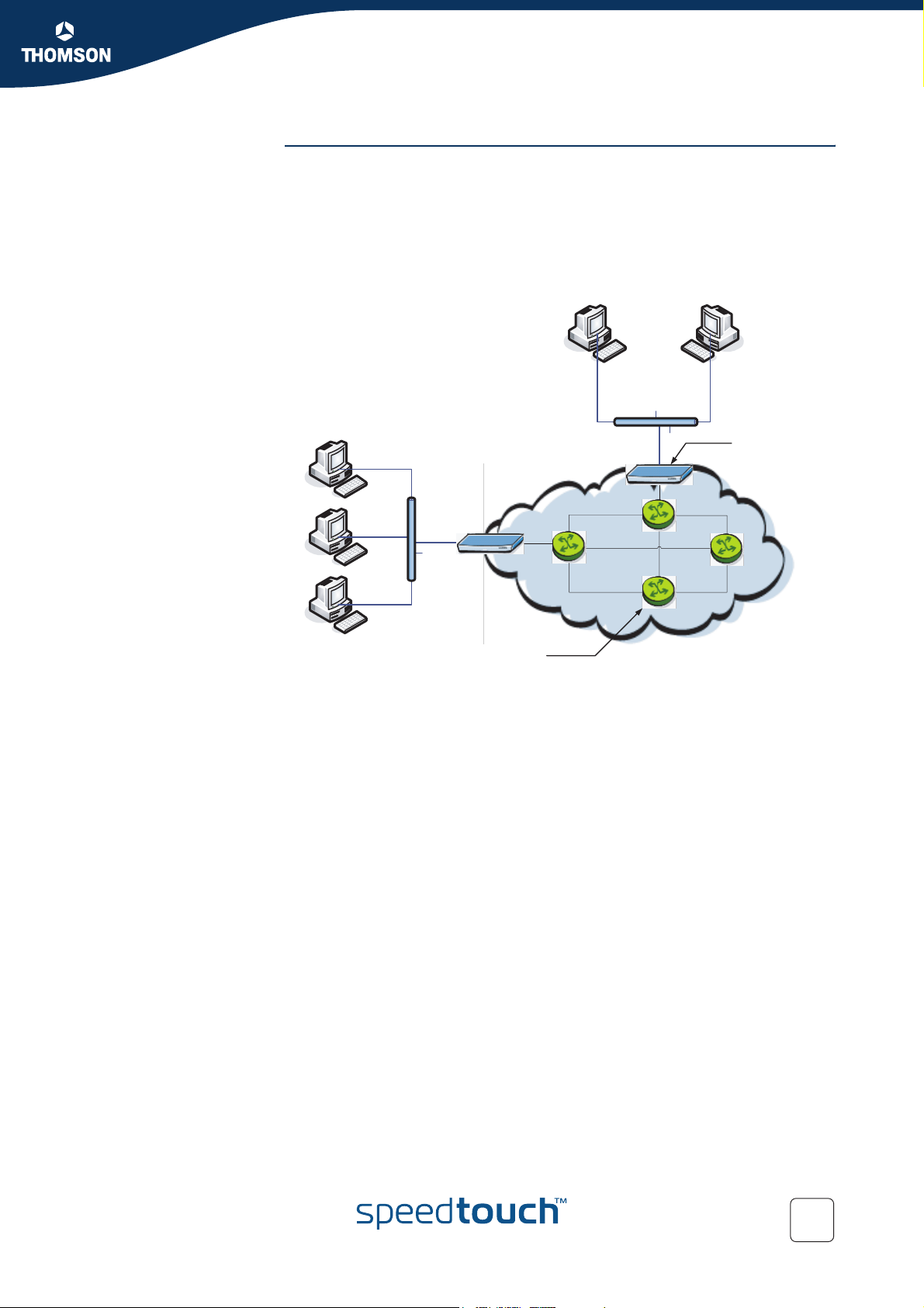
A DiffServ domain consists of a set of DiffServ nodes which can provide the
common service and which have a set of PHBs implemented on each node. The
DiffServ domain has two types of nodes:
boundary nodes at the edges of the domain
interior nodes inside of the domain.
The boundary nodes are the access routers and edge routers that directly peer with
customers (either individual users or other ISPs).
SpeedTouch™
as boundary nod
Router at ISP as
interior node
Interior nodes only connect to other interior nodes or boundary nodes within the
same DiffServ domain.
Both DiffServ node types must be able to apply the appropriate PHB to packets,
according to the DSCP. The boundary nodes are required to perform traffic
conditioning functionality when the functionality of the interior nodes may be limited.
Boundary nodes act both as DiffServ ingress and DiffServ egress node, depending on
the direction of the traffic.
In practice this means that the boundary node makes sure that the TOS/DSCP byte is
set correctly.
E-NIT-CTC-20041213-0013 v0.5
19
Page 22
Chapter 3
Basic QoS Concepts
Traffic classification A packet is classified as belonging to a "class of service". This classification is done
3.3 Classification and conditioning principles
Introduction Packets go through a number of phases as they transit the network: classification,
marking, shaping, policing and queuing. These phases can occur a number of times
at each QoS-aware router in the path of the packet.
For example, a host might mark outgoing traffic as "best effort", "scavenger",
"discard at edge" or "discard at paid link". The hosts router might then police the
host's traffic to ensure that these are the only markings applied to traffic, and remark
invalidly marked packets as "best effort".
The traffic conditioners are usually located in DiffServ boundary nodes, so interior
nodes do not need to perform any traffic conditioning.
by the boundary nodes.
The BA classifier classifies the packets by the DSCP. Classification is based on the
value of combination of one or more IP header fields, such as source and destination
addresses, source and destination ports, protocol ID and other information like
incoming interface.
For example, we might classify data from a VoIP gateway as being "voice" traffic.
Traffic conditioning Traffic conditioning includes metering, policing, shaping and possibly re-marking to
ensure that the traffic stream entering the DiffServ domain conforms to the rules
specified in the SLS. The traffic conditioning policies are negotiated between the
networks and vary from simple re-marking to complex policing and shaping
operations.
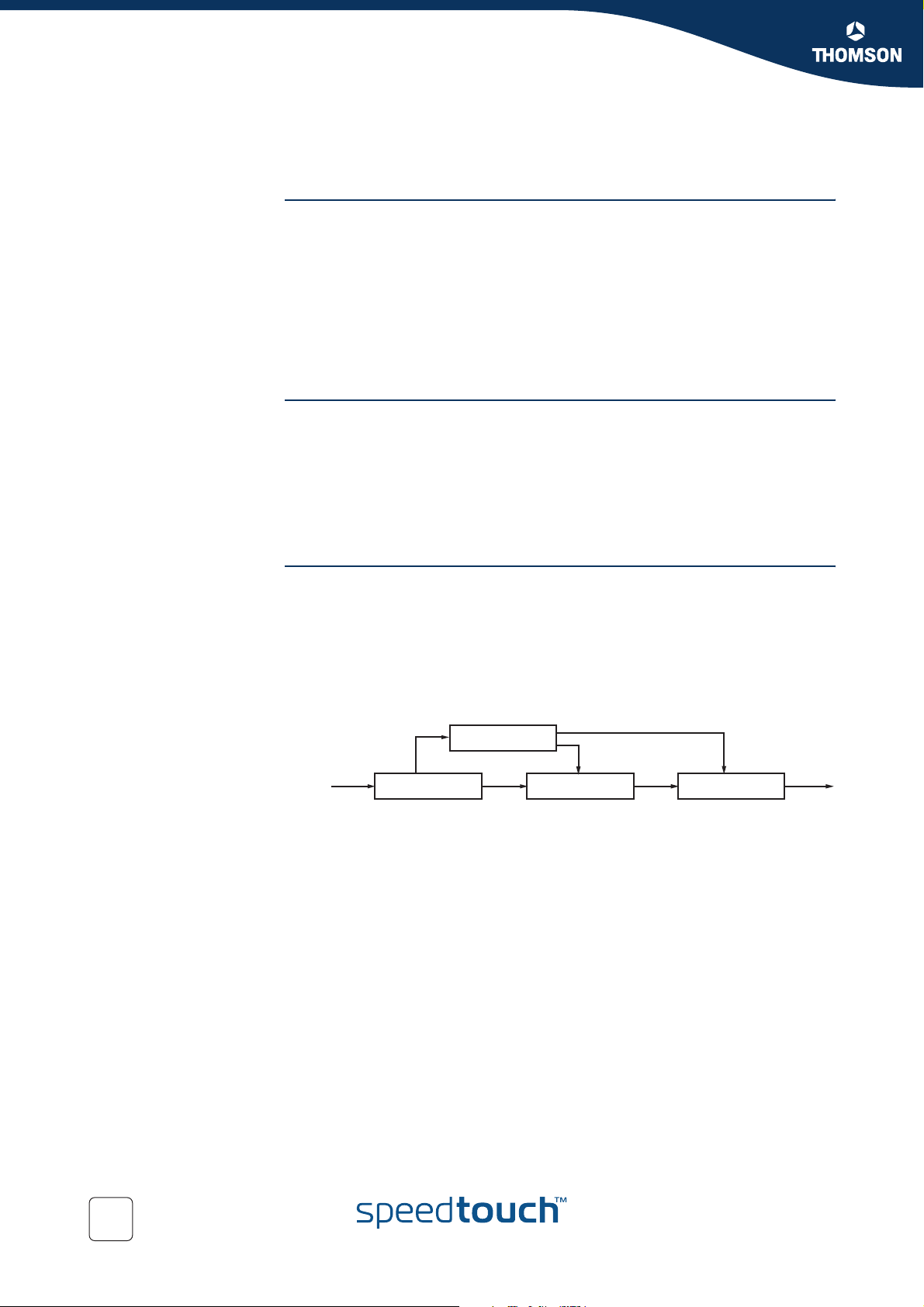
The traffic conditioner includes meter, marker, shaper and dropper. The packets are
directed from the traffic classifier to the logical instance of traffic conditioner.
meter
packet
stream
The figure above shows that the packets travel from the classifier either to the meter
or to the marker.
The meter measures the rate at which packets of one BA pass the meter. It is used
to measure the traffic stream against the traffic profile.
The marker adds the packet to the appropriate BA according to the DSCP. The DSCP
may be changed by the marker, i.e. re-marked.
Shapers shape the packet stream to fit in the used traffic profile. The shaper may
also act as a dropper by dropping packets to fit the stream into the profile.
classifier
marker
shaper/dropper
20
E-NIT-CTC-20041213-0013 v0.5
Page 23

Basic QoS Concepts
Marking Once classified, a packet is marked to avoid repeated re-classifications. The marking
is made to the Differentiated Services Code Point (DSCP). The DSCP is trusted by
later routers, so that the high cost of classifying traffic occurs only once.
Shaping At the outgoing network edge, traffic is shaped to meet the traffic contract.
Metering At the outgoing network edge, traffic is metered to meet the traffic profile. This
means that the bandwidth can be limited for certain traffic.
Policing At the incoming network edge traffic is measured and traffic in excess of the traffic
contract is either re-marked to "best effort" or discarded.
Chapter 3
E-NIT-CTC-20041213-0013 v0.5
21
Page 24

Chapter 3
Basic QoS Concepts
3.4 Differentiated Services Code Point (DSCP)
Introduction A small bit-pattern, called the DS field, in each IP packet is used to mark the packets
that should receive a particular forwarding treatment. The DS field uses the space of
the former ToS byte in the IPv4 IP header and the traffic class byte in the IPv6
header. All network traffic inside of a domain receives a service that depends on the
traffic class that is specified in the DS field.
The structure of the DS field is shown below:
7 6 5 4 3 2 1 0
DSCP ECN
A six-bit field, known as the Differentiated Services Code Point (DSCP), in the DS
field specifies the PHB for a given flow of packets. The DSCP is composed of the six
most significant bits of the DS field. The two least significant bits of the DS field are
used for Explicit Congestion Notification (ECN) by DiffServ-capable nodes that
support ECN. The ECN field contains 2 bits, the ECT bit and the CE bit.
The ECT bit is set to 1 to advertise to the network that the node is an ECN capable
node.
The CE bit is set to 1 incase the node experiences congestion.
Refer to RFC2474 for more information on the definition of the DS field.
Per Hop Behaviour Routers look at the DSCP to select a per-hop behaviour, such as a queueing
algorithm and its parameters.
A PHB defines a DiffServ router’s externally observable forwarding behaviour (in
terms of buffer/bandwidth resource allocation) related to a BA. This is essentially
defined by the queuing/scheduling/buffer management in the forwarding path.
PHBs are implemented in DiffServ nodes by means of some buffer management and
packet scheduling mechanism. The PHB definition is not depending on the
mechanism that offers the service but in terms of behaviour characteristics relevant
to service provisioning policy.
For example, "voice" traffic might select a "strict" queuing algorithm with a
parameter of "place in top priority queue".
Refer to RFC2475 for more information.
Standardized PHBs The following specific PHBs and recommended DSCPs for each PHB have been
standardized by the IETF:
Default PHB.
Expedited Forwarding PHB.
Class Selector (CS) PHB.
Assured Forwarding PHB.
22
E-NIT-CTC-20041213-0013 v0.5
Page 25

Chapter 3
Basic QoS Concepts
E-NIT-CTC-20041213-0013 v0.5
23
Page 26

Chapter 3
Basic QoS Concepts
Assured Forwarding
(AF) PHB Group:
The Assured Forwarding (AF) PHB group allows a provider to offer different levels of
forwarding assurances for IP packets. The delivery of IP packets is provided in four
independently forwarded AF classes (AF1x through AF4x). Each AF class is allocated
a certain amount of forwarding resources (buffer space and bandwidth) in a DS node.
Within each AF class, there are three drop probabilities: Low, Medium and High drop
precedence (the higher the precedence, the higher the probability the packet will be
dropped in case of congestion).
Packets can be selected for a PHB based on required throughput, delay, jitter, loss, or
according to priority of access to network services.
The table below illustrates the recommended DSCP coding for specifying the AF
class with the drop probability. The AF value, the decimal value and the binary value
are shown for each DSCP.
Drop Precedence Class 1
AF1
Low Gold
AF11
10
(001010)
Medium Silver
AF12
12
(001100)
Class 2
AF2
Gold
AF21
18
(010010)
Silver
AF22
20
(010100)
Class 3
AF3
Gold
AF31
26
(011010)
Silver
AF32
28
(011100)
Class 4
AF4
Gold
AF41
34
(100010)
Silver
AF42
36
(100100)
High Bronze
AF13
14
(001110)
For more information on the AF PHB, refer to RFC2597.
Bronze
AF23
22
(010110)
Bronze
AF33
30
(011110)
Bronze
AF43
38
(100110)
24
E-NIT-CTC-20041213-0013 v0.5
Page 27

IP QoS Framework Overview
4 IP QoS Framework Overview
Introduction This chapter presents an overview of the main components of the IP QoS framework
within the SpeedTouch™.
In this chapter
Topi c Pag e
4.1 Main Framework Components 26
4.2 Resource Management 27
Chapter 4
E-NIT-CTC-20041213-0013 v0.5
25
Page 28
Chapter 4
W
IP QoS Framework Overview
Graphical overview The figure below shows a graphical overview of the main components in the
4.1 Main Framework Components
upstream datapath.Notice that there are two main blocks, the input and output.
In between these two blocks the IP packets go through a series of processes like
firewall, nat etc.
INPUT OUTPUT
MANAGEMENT
ETH
ireless
LAN
USB
RESOURCE
Classification
IP forwarding
destination
or
label-based
QoS Components The main QoS components are:
Resource Management: The main purpose of this module is to assure that
arriving low priority data cannot consume all the internal memory resources. In
case of congestion and resource starvation, this module will deny low priority
data from consuming memory resources. The Resource Management module
also maps the Layer 2 VLAN user priority to an internal Class.
Classification: The classification module classifies incoming data. Data that
matches the classification criteria will be labelled. A label is only of internal
significance and can be used in forwarding and QoS definition. Each label can
have an internal QoS class associated with it. Data will experience treatment
(queuing and scheduling) according to its QoS class. The SpeedTouch™
Business DSL Router support 16 internal classes which are linked to the 6
queues. The 6 queues are:
The Real Time queue (EF)
The Weight Fair queue 4 (WFQ4)
The Weight Fair queue 3 (WFQ3)
The Weight Fair queue 2 (WFQ2)
The Weight Fair queue 1 (WFQ1)
The Best Effort queue (BE)
There are 6 queues defined per ATM interface. So each ATM interface
can have different QoS settings.
Packect
handeling
MANAGEMENT
RESOURCE
IP QoS
queueing
+
scheduling
+
rate limiting
ATM
QoS
DSL
IP Forwarding: IP forwarding supports the use of labels to forward classified
data to any IP interface. This allows, for example, to forward data based upon
port(-ranges), IP addresses, protocol, source interface, Differentiated Services
Code Point (DSCP), … (see the “Routing Configuration Guide” for more details
on routing and forwarding)
IP QoS Queuing, Scheduling and Rate Limiting: This module implements the
internal IP QoS queues and scheduling and maps the internal class (set during
classification or set by the Resource management module) to one of these
queues. Rate-limiting can be configured for the fixed priority real-time queue.
This queue has fixed priority over other queues. This ensures a low latency but
could lead to starvation of lower priority queues. By configuring a percentage of
the total available interface bandwidth, data from this queue will be limited to
this bandwidth in case of congestion.
ATM QoS: The ATM Quality of Service module holds the extensive ATM QoS
features, starting with per ATM VP/VC queuing and shaping, per ATM QoS
class queuing and scheduling, performing connection admission control.
26
E-NIT-CTC-20041213-0013 v0.5
Page 29

Chapter 4
IP QoS Framework Overview
4.2 Resource Management
Introduction The RM module reserves memory for four independent traffic classes. Resources are
reserved for each RM-class, both in the upstream and in the downstream direction (8
reservations in total). The figure below shows the Resource Management
reservations.
Dynamic Memory Pool
resource
reservation
For incoming data towards the IP host, this module copies the VLAN user priority
field into the packet internal class indication. The module also sets (or raises) the
internal class indication based upon the ATM VP/VC QoS category for reassembled
frames.
As a result, incoming low priority UBR (Unspecified Bit Rate) traffic will not be able to
consume all resources because resources are reserved for VBR (Variable Bit Rate)
and CBR (Constant Bit Rate) data. Similarly, low priority VLAN frames won't be able
to consume all resources because resources are reserved for high priority (based
upon the VLAN user priority field) VLAN frames.
0 1 2 3
UPSTREAM
0 1 2 3
DOWNSTREAM
E-NIT-CTC-20041213-0013 v0.5
27
Page 30
Chapter 4
IP QoS Framework Overview
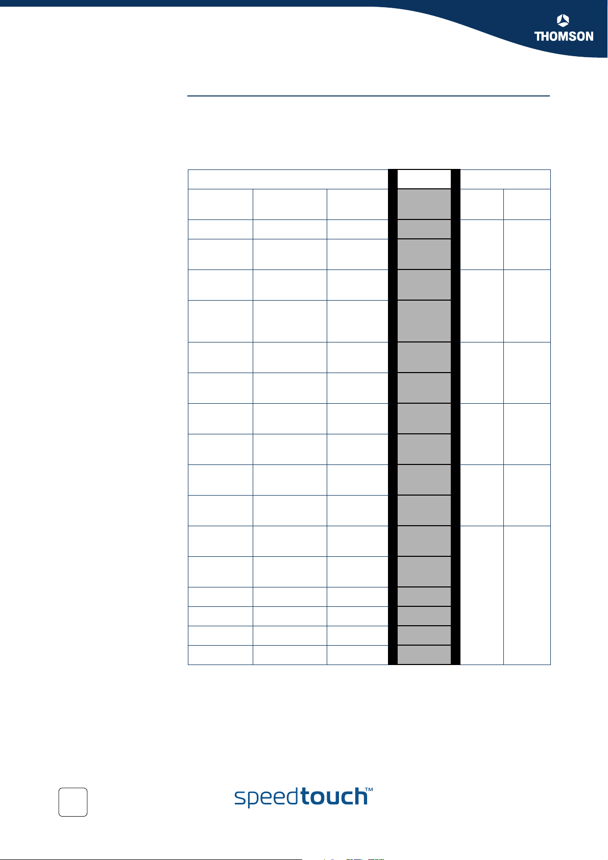
Mapping to internal
class
The RM module maps packets to the an internal class depending on ATM QoS, VLAN
priority or DSCP settings. The table below shows the relation between these
settings. Once the mapping to the internal classes has been completed the packet
goes through a number of processes like firewall, nat etc. Finally once the packet is
ready for output it will be put in one of the 6 queues based upon its internal class.
INPUT
ATM QoS
Category
CBR 7 CS6,CS7
VBR-rt 6
VBR-nrt
(low CDVT)
GFR
(low CDVT)
VBR-nrt
(high CDVT)
GFR
(high CDVT)
VLAN User
Priority
-
-
-
5
DiffServ
DSCP
EF
CS5
AF41
CS4
AF42,AF4
3
AF31
CS3
AF32,AF3
3
Mapping OUTPUT
Internal
Class
15
14
13
12
11
10
Queue Label
5
4WFQ4
3WFQ3
Real
Time
--
-4
UBR BCS 7 -
ABR /UBR
BCS 6
UBR-mdcr /
UBR BCS 5
UBR / UBR
BCS 4
UBR BCS 3 - - 3
UBR BCS 2 2 - 2
UBR BCS 1 - - 1
UBR BCS 0 1 - 0
3
--
0
AF21
CS2
AF22,AF2
3
AF11
CS1
AF12,AF1
3
CS0
Best Effort
9
2WFQ2
8
7
1WFQ1
6
5
4
0
Best
Effort
28
E-NIT-CTC-20041213-0013 v0.5
Page 31

Packet Classification and Labelling
5 Packet Classification and Labelling
Introduction This chapter will explain in detail how packets are classified. This classification is
configured via rules in a packet filter mechanism.
When a packet hits a rule, it will be marked with the label that is associated with this
rule. Like this, packets with certain properties can be given a common name.
Next to the name of the label, also some parameters are linked to the packet(s).
These parameters can be QoS values, priorities and actions like ToS marking etc.
In this chapter
Topi c Pag e
5.1 Classification 30
5.2 Labels 33
Chapter 5
5.3 Rules 42
5.4 Chains 49
5.5 Expressions 52
E-NIT-CTC-20041213-0013 v0.5
29
Page 32

Chapter 5
Packet Classification and Labelling
5.1 Classification
Introduction The basic objective of the Classification module in the SpeedTouch™ is the following:
Terminology Labelling means assigning a user friendly name to classified types of connections for
Identifying certain data (on IP or layer 3 level) (called classification)
Stating the importance (or priority) of the data, optionally overruling the priority
already indicated by the layer 2 network (setting the internal class)
The internal class is an internal indication (from 0..15) of the importance/
priority of data, this determines how the data will be treated (to which queue
it will be mapped).
internal usage.
The outcome of packet classification is a label. This label can be used within the
router to refer to particular classified data.
Classification allows to "label" data based upon a set of packet filter rules.
Rules have an action to assign a label to all packets to which one particular rule
applies.
Expressions are user friendly names to represent Services, Interfaces and IP
concepts.
30
E-NIT-CTC-20041213-0013 v0.5
Page 33

Chapter 5
qos_default_rule_n
_1
_2
Routing classification
Packet Classification and Labelling
5.1.1 Order of classification rules
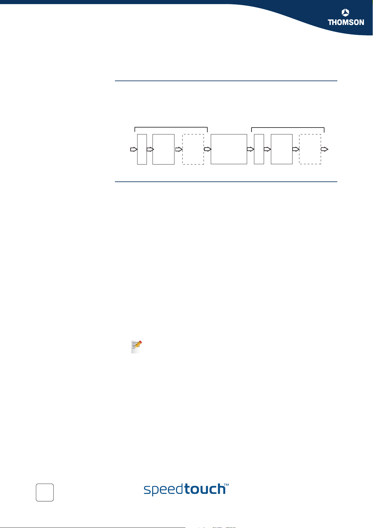
Introduction The SpeedTouch™ will first check the routing rules and assign a routing-label when a
rule is hit. Secondly the packet will go through the QoS rules and a qos-label will be
assigned if a rule is hit. So each packet can get two labels assigned.
The figure below shows an example of the hierarchical order of classification rules:
0
rt_user_labels
1
rt_default_labels
0
rt_user_rule_1
1
rt_user_rule_2
0
rt_default_rule_1
1
rt_default_rule_2
QoS classification
0
qos_user_labels
1
qos_default_labels
The order of the classification rules (determined by the rule index) is very
!
important. The first rule that applies to a packet determines which label will
be assigned to that packet. When a rule applies to a packet in the routing
classification, the rule matching process stops and the QoS classification
starts untill the first rule is hit and a label is assigned.
0
qos_user_rule_1
1
qos_user_chain_1
2
qos_user_rule_2
3
qos_user_rule_n
0
qos_default_rule_1
1
qos_default_rule_2
2
chain_rule
chain_rule
Sub-chains In case sub-chains are linked within a chain, these sub-chains have an index and the
E-NIT-CTC-20041213-0013 v0.5
sub-chain rules are matched before the rules with the following index in the parent
chain.
Routing parameters only apply to routing labels; QoS parameters only apply
to QoS labels
31
Page 34

Chapter 5
Packet Classification and Labelling
Example So, in the example shown in the previous figure, the rules will be applied to incoming
packets in the following order:
1 routing labels
1 routing user labels
2 routing default labels
2 qos labels
1 qos user labels
2 qos default labels
No rules should be created in the chain _default_labels, because this chain is
!
reserved for automatically created rules that substitute source-routes where
needed. When creating classification rules, only create them in the chain
_user_labels or in newly created sub-chains in the chain _user_labels.
32
E-NIT-CTC-20041213-0013 v0.5
Page 35

Chapter 5
Packet Classification and Labelling
5.2 Labels
Introduction This section will explain in detail how to configure labels through the CLI.
As mentioned before labels are used to assign a user friendly name to a packet for
internal usage.
The same label can be used in both Routing label rules and QoS label rules.
!
Its name/ID will be used for forwarding, its parameters will be used for QoS
related queuing, rate-limiting or marking.
CLI Command groups The label command group is build up out of one main group called label and two sub-
groups called chain and rule. The sub-group rule has one more sub-group called
debug.
The command group and sub-groups in detail.
Label command group
label add
modify
delete
list
flush
chain
rule
Chain command group
chain add
delete
list
flush
Rule command group
E-NIT-CTC-20041213-0013 v0.5
rule add
delete
modify
list
flush
debug
33
Page 36

Chapter 5
Packet Classification and Labelling
Adding a label Execute the following CLI command to add a label:
Label parameters Now that we have added a label we can configure its parameters.
Debug command group
debug traceconfig
stats
clear
{Administrator}=>:label add name mylabel
The example above will add a label with the name “mylabel”
The following label parameters can be configured:
Parameter Description
name The name of a label to modify.
classification The Method of classification.
defclass The default class of assigned connection.
ackclass The class of ACK segments of TCP connection.
bidirectional The label is also valid for return stream.
inheritance The label is also valid for corresponding stream of child
connection.
tosmarking Enable/disable TOS marking.
tos The Type Of Service specification in the IP packet (used for
tos-marking).
dscp The diffserv code point (part of tos, used for tos-marking).
precedence The precedence (part of tos, used for tos-marking).
ttloverwrite Enable/disable ttl overwrite.
ttl The Time To Live in the IP packet (used for ttl-overwrite).
trace Enable/disable IP tracing for this label.
34
The TTL parameters are only used for packet routing and the trace parameter is used
for debugging.
E-NIT-CTC-20041213-0013 v0.5
Page 37

Chapter 5
Packet Classification and Labelling
5.2.1 Label parameters explained
Introduction This section will explain in detail the label parameters and their values.The first part
explains the parameters used to set the priority for internal use like mapping to one
of the 16 internal classes. The second part will explain the parameters that need to
be set to enable QoS throughout the entire network.
Classification The classification parameter determines whether the label classification will set the
internal class (used to determine the IPQoS queue).
Classification values Description
ignore If set to "ignore", the label classification will ignore the
existing packet class and will not set or overwrite the
internal class.
overwrite If set to "overwrite", the label classification will set the
packet class based upon the configured class
parameter, regardless of what the existing packet
class value is.
increase If set to "increase", the label classification will only set
the packet class IF the configure class parameter is
higher than the existing packet class value.
Defclass The defclass parameter is used to select the DiffServ queue if DiffServ is enabled on
the destination interface on which the data is forwarded. By default 4, being the
best-effort queue.
Defclass values Description
0..15 The internal class number.
dscp If this value is used the defclass value is set to the
dscp value. The diffserv code point is automatically
mapped to an internal class corresponding to the DSCP
PHB.
default If selected the defclass value is set to the
SpeedTouch™ default value of 4.
E-NIT-CTC-20041213-0013 v0.5
35
Page 38

Chapter 5
Packet Classification and Labelling
Ackclass The ackclass parameter is used to select the DiffServ queue for single ACK segments
Bidirectional Bi-directional labeling of connections is used to copy the label (Routing and/or QoS)
of a TCP connection.
Ackclass values Description
0..15 The internal class number.
prioritize If selected the ACK segments will be given a higher
priority than the defclass. (Ackclass +2)
defclass If selected the same class will be used as defined in
the defclass parameter.
from the initiator stream to the returning stream. Bi-directional labels cannot be used
in the forwarding table.
Bidirectional values Description
disable Disables the label for the return stream.
enable Enables the label for the return stream.
Inheritance When inheritance is enabled, this label will be copied to streams of all child
connections in the same direction (so for a bi-directional label to all child streams).
This allows to automatically classify (label) child streams and/or connections using
any supported ALG
A child connection is a connection that is setup automatically by a parrent
connection.
Inheritance values Description
disable Disables the label for child connections.
enable Enables the label for child connections.
Example In active mode FTP the client connects from a random unprivileged port (N > 1024)
to the FTP server's command port, port 21. Then, the client starts listening to port
N+1 and sends the FTP command PORT N+1 to the FTP server. The server will
then connect back to the client's specified data port from its local data port, which is
port 20.
From the server-side firewall's standpoint, to support active mode FTP the following
communication channels need to be opened:
FTP server's port 21 from anywhere (Client initiates connection)
FTP server's port 21 to ports > 1024 (Server responds to client's control port)
FTP server's port 20 to ports > 1024 (Server initiates data connection to
client's data port)
FTP server's port 20 from ports > 1024 (Client sends ACKs to server's data
port)
36
E-NIT-CTC-20041213-0013 v0.5
Page 39

Packet Classification and Labelling
In this case the child connection would be the connection on port 20 of the FTP
server.
Chapter 5
E-NIT-CTC-20041213-0013 v0.5
37
Page 40

Chapter 5
Packet Classification and Labelling
5.2.2 Using TOS, DSCP or Precedence
Introduction In this section we will explain the parameters that need to be set to enable QoS
TOSmarking When using TOS a very fine definition of the Quality of Service can be made. This is
throughout the entire network. This means that these values are only of significance
for outgoing fraffic. The tables below describe the values used when configuring
IPQoS by setting the TOS byte, using DSCP or by setting the Precedence bits.
Only one type of of IPQoS can be used at the time.
!
only of use when the whole network supports QoS by TOS.
TOSmarking values Discription
disable Disables the TOS marking.
enable Enables the TOS marking.
TOS
Precedence
TOS values Description
1..255 Sets the TOS bits in the IP header to the coresponding
value.
When using Precedence the QoS definition is narrowed down to 8 values
Precedence values Description
routine will set the precedence bits to 000. (lowest
priority)
priority will set the precedence bits to 001.
immediate will set the precedence bits to 010.
flash will set the precedence bits to 011.
flash-override will set the precedence bits to 100.
CRITIC-ECP will set the precedence bits to 101.
internetwork-control will set the precedence bits to 110.
network-control will set the precedence bits to 111. (highest priority)
38
number 0..7 0..7.
E-NIT-CTC-20041213-0013 v0.5
Page 41

Packet Classification and Labelling
DSCP When using DSCP the QoS definition is narrowed down to 21 values. This is the
most common value used to define QoS. This definition is also backwards compatible
with TOS and Precedence.
DSCP values Description
Chapter 5
ef|af11|af12|af13|af2
1|af22|af23|af31|af32
|af33|af41|af42|af43|
cs0|cs1|cs2|cs3|cs4|
cs5|cs6|cs7
number 0..63 A decimal value can also be used to define the service
These are the values that can be used to define the
service class by DSCP.
Example: EF = Expedited forwarding or Real time.
class.
E-NIT-CTC-20041213-0013 v0.5
39
Page 42

Chapter 5
Packet Classification and Labelling
5.2.3 Forwarding parameters.
Introduction In this section we will explain the parameters that need to be set to enable packet
TTLoverwrite The following parameters can be configured for routing purposes.
forwarding throughout the entire network. This means that these values are only of
significance for outgoing fraffic.
TTLoverwrite values Description
disable Disables the overwriting of the IP header TTL field with
the configured TTL value.
enable Enables the overwriting of the IP header TTL field with
the configured TTL value
TTL
TTL values Description
1..255 The time to live in number of hops (routers) that the
packet will be forwarded.
The TTL value is normaly set to a high number to avoid that packets get dropped.
For IGMP packets the TTL is by default set to 1. If we want IGMP packets to get
routed to the next router the TTL value should be set to 2.
Modify the label
Execute the following CLI command to configure the label parameters:
parameters
{Administrator}=>: label modify name mylabel classification overwrite
defclass 14 ackclass 14 bidirectional disabled inheritance disabled
tosmarking disabled
Show all labels defined Exectute the following CLI command to show all defined labels:
{Administrator}=>:label list
This command will return you all labels defined.
40
Name Class Def Ack Bidirect Inherit Tosmark Type Value Ttlover Ttl Use Trace
DSCP overwrite dscp defclass disabled disabled disabled tos 0 disabled 0 0 disabled
Interactive increase 8 8 disabled disabled disabled tos 0 disabled 0 0 disabled
Management increase 12 12 disabled disabled disabled tos 0 disabled 0 0 disabled
Video increase 10 10 disabled disabled disabled tos 0 disabled 0 0 disabled
VoIP overwrite 14 14 enabled enabled disabled tos 0 disabled 0 0 disabled
default increase default prioritize disabled disabled disabled tos 0 disabled 0 0 disabled
E-NIT-CTC-20041213-0013 v0.5
Page 43

Chapter 5
Packet Classification and Labelling
Deleting a label Labels can be deleted one by one with the delete command. To delete all labels we
use the flush command.
Execute the following CLI command to delete a specific label:
{Administrator}=>:label delete name mylabel force enabled
Execute the following CLI command to delete all the labels at once:
{Administrator}=>:label flush
The flush command offers the possibility to force the deletion of labels that
are still in use. To do so add force=enabled to the flush command.
E-NIT-CTC-20041213-0013 v0.5
41
Page 44

Chapter 5
Packet Classification and Labelling
5.3 Rules
Introduction Rules are used to define two things:
Adding a selection rule As mentioned before a label will only be assigned to a packet if this packet complies
The relation between the chains.
The criteria to check before assigning a label to a packet.
We will only discuss rules used to assign a label to a packet in this document.
to a certain rule. These rules have to be defined in the rule subgroup.
Execute the following CLI command to add a rule:
{Administrator}=>:label rule add chain=qos_user_labels index=2 name=ftp
srcintf=lan srcip=10.0.0.1 serv=ftp log=enabled state=enabled
label=mylabel
Example explained This command adds a rule under the qos_user_labels named ftp with index 2.
This rule applies to data coming from the LAN interface with source address
10.0.0.1 and of the type FTP. Packets matching this rule will be labeled with the
label “mylabel”
If no index is specified the SpeedTouch™ will automatically use the next available
index number .
42
E-NIT-CTC-20041213-0013 v0.5
Page 45

5.3.1 Rules parameters explained
Introduction These are the parameters that can be used to define a rule.
We will now have a closer look at these parameters and explain what they are used
for.
Chain
Chain values Description
Chain name The name of the chain or subchain which contains the
rule.
Index
Chapter 5
Packet Classification and Labelling
Name
Clink
Srcintf
Index values Description
number 0..255 The list number of the rule. The lower the number the
higher the rule is placed in the list. This is of very high
importance since this will be the sequence in which the
are rules a checked.
Name values Description
String The name of the new rule.
Clink values Description
String Name of chain to be parsed when rule applies.
Srcintf values Description
E-NIT-CTC-20041213-0013 v0.5
DHCP-R_if_0, wan, lan,
local, _Internet, _lan1,
HTTPI_if_0, HTTP_if_0,
HTTPs_if_0, FTP_if_0,
TELNET_if_0, DNSS_if_0,
SNMP_AGENT_if_0,
PING_RESPONDER_if_0
The name of the source interface expression.
43
Page 46

Chapter 5
Packet Classification and Labelling
Srcip
Srcip values Description
Dstip
Serv
private, ssdp_ip,
mdap_ip, _10.0.0.138,
_192.168.1.254
Dstip values Description
private, ssdp_ip,
mdap_ip, _10.0.0.138,
_192.168.1.254
Serv values Description
HTTP_sv_0,
HTTPs_sv_0, FTP_sv_0,
TELNET_sv_0,
RIP_sv_0,
RIP_Query_sv_0,
DNS_S_sv_0,
DHCP_R_sv_0,
DHCP_S_sv_0,
SNMP_AGENT_sv_0,
SSDP_sv_0,
MDAP_sv_0,
RAS_sv_0, SRAS_sv_0,
ICMP_LISTEN_sv_0,
SENDTO_LISTEN_sv_0,
PING_RESPONDER_sv_
0, icmp, igmp, ftp,
telnet, http, httpproxy,
https, RPC, NBT, SMB,
imap, imap3, imap4-ssl,
imaps, pop2, pop3,
pop3s, smtp, ssh, dns,
nntp, ipsec, esp, ah,
ike, DiffServ, sip, h323,
dhcp, rtsp, ssdp_serv,
mdap_serv, syslog,
HTTPI_sv_0
The srcip parameter is used to the source address of
the packet, this can be any ip address. If the source ip
parameter is left open any source address is valid.
The dstip parameter specifies the destination address
of the packet.
This can be used for point to point connections.
If the dstip parameter is left open any destination
address is valid.
The serv parameter defines the service used, this can
be any given service or a specific service like HTTP,
FTP, TELNET etc. These services can be defined in the
expression command group wich will be explained in
detail further on.
44
E-NIT-CTC-20041213-0013 v0.5
Page 47

Log
State
Chapter 5
Packet Classification and Labelling
Log values Description
enable Enables logging when this rule applies. This can be
used for debugging.
disable Disables logging
State values Description
enable Enables this rule.
disable Disables this rule.
Label
Label value Description
none If no label needs to be assigned.
link Link is used incase the clink parameter is used.
label name The name of the label you want to assign to a packet
when the rule applies.
Modifying a rule
Rules that have been created can be modified with the modify command. The
parameters for the modify command are exactly the same as those for the add
command.
The list command The list command can be used to view a list of the rules created. This command can
be refined with the following parameters:
chain
format.
With the chain suffix a chain name can be specified, so only the rules that apply to
that chain will be shown.
With the format suffix we can select the output format. The default format is pretty,
the other option is cli
Example. Execute the following CLI command to view the rules that are related to
the chain qos_default_labels:
E-NIT-CTC-20041213-0013 v0.5
{Administrator}=>:label rule list chain=qos_default_labels format=cli
45
Page 48

Chapter 5
Packet Classification and Labelling
The output of this command will look like this:
:label rule add chain=qos_default_labels index=1 serv=sip log=disabled
state=enabled label=VoIP
:label rule add chain=qos_default_labels index=2 serv=h323 log=disabled
state=enabled label=VoIP
:label rule add chain=qos_default_labels index=3 serv=telnet log=disabled
state=enabled label=Interactive
:label rule add chain=qos_default_labels index=4 serv=smtp log=disabled
state=enabled label=Interactive
:label rule add chain=qos_default_labels index=5 serv=imap4-ssl log=disabled
state=enabled label=Interactive
:label rule add chain=qos_default_labels index=6 serv=imap3 log=disabled
state=enabled label=Interactive
:label rule add chain=qos_default_labels index=7 serv=imap log=disabled
state=enabled label=Interactive
:label rule add chain=qos_default_labels index=8 serv=imaps log=disabled
state=enabled label=Interactive
:label rule add chain=qos_default_labels index=9 serv=pop3s log=disabled
state=enabled label=Interactive
:label rule add chain=qos_default_labels index=10 serv=pop3 log=disabled
state=enabled label=Interactive
:label rule add chain=qos_default_labels index=11 serv=pop2 log=disabled
state=enabled label=Interactive
:label rule add chain=qos_default_labels index=12 serv=httpproxy log=disabled
state=enabled label=Interactive
:label rule add chain=qos_default_labels index=13 serv=http log=disabled
state=enabled label=Interactive
:label rule add chain=qos_default_labels index=14 serv=https log=disabled
state=enabled label=Interactive
:label rule add chain=qos_default_labels index=15 serv=esp log=disabled
state=enabled label=Interactive
This is only an example of the output, it is possible that the values represented here
do not match your output.
The flush command The flush command can be used to delete all rules at once or to delete all rules in a
chain.
Execute the following CLI command to delete all rules that we created in the chain
“qos_user_labels”:
{Administrator}=>:label rule flush chain qos_user_labels
This command will delete all the rules related to the chain qos_user_labels.
46
E-NIT-CTC-20041213-0013 v0.5
Page 49

Packet Classification and Labelling
5.3.2 Rule debug commands
Introduction Under the subgroup rule there is an other subgroup called debug. This subgroup is
used to debug the rules.
There are only three parameters that can be used here :
Traceconfig
Traceconfig values Description
enable If the parameter has been enabled the label rules will
be shown in the trace output.
disable If the parameter has been disabled the label rules will
not be shown in the trace output.
Execute the following CLI command to enable the trace output:
Chapter 5
{Administrator}=>:label rule debug label rule debug traceconfig
state=enabled
To enable the trace output press “Ctrl+Q” in the CLI connection to disable
the trace output press “Ctrl+S”
Traceconfig result The output will look similar to this one:
[PF] chain qos_default_labels rule 17:
[PF] > expr serv ike
[PF] > - expr serv ike
[PF] chain qos_default_labels rule 18:
[PF] > expr serv icmp
[PF] > + expr icmp[1] : proto=1
[PF] > + expr serv icmp
[PF] chain qos_default_labels rule 18 applies, processing STOP,
returning 2
When a packet is received it will be checked against all the rules.
On the first line we see that the packet is checked against the rule 17 in the chain
qos_default_labels.
On the second line we see that rule 17 aplies to all packets of the ike type.
Line three shows that the packet does not match the rule. (- expr serv ike)
Line four shows the next rule that will be checked. This is rule 18 of the chain
qos_defqult_labels.
Line five shows that this rule applies to all packets of the icmp type.
Line six and seven show that this rule applies to this packet. (+ expr serv icmp)
Line eight shows that the rule matching has ended.
E-NIT-CTC-20041213-0013 v0.5
47
Page 50

Chapter 5
Packet Classification and Labelling
Stats Execute the following CLI command to show the statistics of all rules.
{Administrator}=>:label rule debug stats
The output can be refined by adding the chain and index of the rule you want to see
the stats from.
For Example: The following CLI command will give you the stats for the rule under
qos_default_labels with index number 19.
{Administrator}=>:label rule debug stats chain=qos_default_labels
index=19
The output will show you this:
{Administrator}=>:label rule debug stats chain=qos_default_labels
index=19
chain index packets bytes
-------------------------------------------------------------
qos_default_labels 18 1953 133116
Execute the following CLI command to clear the statistics of the rules:
{Administrator}=>:label rule debug clear
As possible with the stats command, the clear command can be refined by adding a
chain name and/or index number.
48
E-NIT-CTC-20041213-0013 v0.5
Page 51

Packet Classification and Labelling
5.4 Chains
Introduction A chain or sub-chain can be useful for personal ordering or grouping but is not
necessary. You can also place the rules in the _user_labels chain.
The following default chains will be configured:
Routing_Labels: chain for routing label rules; if there is a match in this chain (or
it's subchains), the corresponding label is used as stream routing label.
rt_user_labels: subchain of Routing_Labels for all user added label rules;
overrules auto-routing-label-rules.
rt_default_labels: subchain of Routing_Labels for default routing label rule; will
be overruled by auto-routing-label-rules.
QoS_Labels: chain for QoS label rules; if there is a match in this chain or it's
subchains, the corresponding label is used as stream qos label.
qos_user_labels: subchain of QoS_Labels for user added label rules; overrules
auto-qos-label-rules
qos_default_labels: subchain of QoS_Labels for default QoS label rules; will be
overruled by auto-qos-label-rules
Chapter 5
Adding a chain As seen before in “5.1.1 Order of classification rules” chains can be added as
wanted.
Execute the following CLI command to add a chain:
{Administrator}=>:label chain add chain my_chain
Where my_chain is the name of the chain you want to add.
List the chains Execute the following CLI command to see a list of all the chains:
{Administrator}=>:label chain list
This command will return you all chains defined:
Chains
======
Name Description
-----------------------------------------------------------------
routing_labels system
rt_user_labels user
rt_default_labels user
qos_labels system
qos_user_labels user
qos_default_labels user
my_chain user
E-NIT-CTC-20041213-0013 v0.5
49
Page 52

Chapter 5
Packet Classification and Labelling
Delete a chain The chains can be deleted one by one or they can all be deleted with a single
command.
Execute the following CLI command to delete a single chain:
{Administrator}=>:label chain delete chain my_chain
Execute the following CLI command to delete all chains at once:
{Administrator}=>:label chain flush
50
E-NIT-CTC-20041213-0013 v0.5
Page 53

Chapter 5
q
_1
_2
Packet Classification and Labelling
5.4.1 Define a relation between chains
Introduction If sub-chains are created manualy they need to be linked to a parent chain, this can
be done as follows.
Execute the following CLI command to define the relation ship between the
my_chain chain and the qos_user_labels chain:
{Administrator}=>:label rule add chain=qos_user_labels index=1
clink=my_chain label=link
This will add a link between the user chain my_chain and the qos_user_labels.
The chain structure now looks like this:
os_labels
1
qos_user_labels
2
qos_default_labels
3
1
1
2
3
4
5
my_chain
rule_1
rule_2
rule_3
rule_4
rule_5
1
rule
2
rule
E-NIT-CTC-20041213-0013 v0.5
51
Page 54

Chapter 5
Packet Classification and Labelling
5.5 Expressions
Definition Expressions are used in rules for source and destination interface, source and
destination IP address (es) (ranges) and services.
There are three types of expressions :
Interface related expressions. These are expressions related to an interface like:
lan, wan,ipoa, pppoe, pppoa etc.
IP related expressions. These are expressions related to an IP address or range.
Service related expressions. These are expressions related to a service like
HTTP, FTP, IKE, SIP, etc.
Expressions command
The command group expressions (expr) consists of the following commands :
group
Expression command group
expr add
delete
modify
list
flush
Adding an expression Execute the following CLI command to add an expression:
{Administrator}=>:expr add name ftp type serv proto tcp dstport 20
This command has added an expression of the type service with the name ftp using
protocol tcp and destination port 20.
52
E-NIT-CTC-20041213-0013 v0.5
Page 55

Chapter 5
Packet Classification and Labelling
E-NIT-CTC-20041213-0013 v0.5
53
Page 56

Chapter 5
Packet Classification and Labelling
Bridgeport
bridgeport value Description
number A bridge port can be selected by using the bridge port
number
The bridgeport number can be found in the eth subgroup. Under the eth bridge
subgroup. Execute the following CLI command to find the bridgeport number:
{Administrator}=>:eth bridge iflist
The command will give an output like this :
OBC : dest : Internal
Connection State: connected Retry: 10
Port: OBC PortNr: 0 PortState: forwarding Interface: up
RX bytes: 24774 frames: 163
ethport1 : dest : ethif1
Connection State: connected Retry: 10
Port: ethport1 PortNr: 1 PortState: forwarding Interface: up
TX bytes: 27352 frames: 163 dropframes: 0
TX bytes: 0 frames: 0 dropframes: 0
RX bytes: 0 frames: 0
Addr The following parameter is the only parameter used when selecting ip as type.
Tos All of the following parameters can be used to configure an expression of the type
Precedence
addr value Description
ip-range or address The IP address or range to which the expression is
related.
serv.
tos value Description
number (0..255) The tos byte value can also be used to define an
expression related to this value.
precedence value Description
routine,priority,
immediate,flash, flash-
One of these values can be used to define an
expression related to the precedence in the IP packet.
override, CRITICECP,
internetwork-control,
network-control
54
number Also a number can be used to define an expression
related to the precedence in the IP packet.
E-NIT-CTC-20041213-0013 v0.5
Page 57

Dscp
Chapter 5
Packet Classification and Labelling
dscp value Description
Proto
Srcport
ef, af11, af12, af13,
af21, af22, af23, af31,
af32, af33, af41, af42,
af43, cs0, cs1, cs2,
cs3, cs4, cs5, cs6, cs7
number Also a number can be used to define an expression
Only one of the three parameters above should be used depending on the
!
type of IP QoS you are using.(ToS,DSCP or Precedence)
proto value Description
icmp, igmp, ipinip, tcp,
udp, ah, esp, ipcomp
number Also a number can be used to define the protocol. This
One of these values can be used to define an
expression related to the diffserv code point in the IP
packet.
related to the diffserv code point in the IP packet.
Select one of these values to define an expression
related to a protocol.
is the number used in the IP header to define the
protocol used.
srcport value Description
at-echo, at-nbp, atrtmp, at-zis, auth,
bgp,biff,ftp, ftp-data,
gopher, h323,
httpproxy, ike, ils,
imap2, imap3, ingresnet, ipcserver, ipx, irc-o,
irc-u, kerberos, ldap,
login, netbios-dgm,
netbios-ns, netbios-ssn,
netwall, netware-ip, ...
number Also a number can be used to define the source port.
One of these or many other ports can be selected to
define an expression related to a source port.
E-NIT-CTC-20041213-0013 v0.5
55
Page 58

Chapter 5
Packet Classification and Labelling
Srcportend
srcportend value Description
Dstport
Dstportend
at-echo, at-nbp, atrtmp, at-zis, auth,
bgp,biff,...
number Also a number can be used to define the source port
dstport value Description
at-echo, at-nbp, atrtmp, at-zis, auth,
bgp,biff,...
number Also a number can be used to define the destination
dstportend value Description
at-echo, at-nbp, atrtmp, at-zis, auth,
bgp,biff,...
One of these or many other ports can be selected to
define an expression related to a source port range.
range.
One of these or many other ports can be selected to
define an expression related to a destination port.
port.
One of these or many other ports can be selected to
define an expression related to a destination port
range.
Icmptype
number Also a number can be used to define the destination
port range.
icmptype value Description
echo-reply, destinationunreachable, sourcequench, redirect, echorequest, routeradvertisement, routersolicitation,...
number
One of these values can be used to define an
expression related to the ICMP value in a packet.
56
E-NIT-CTC-20041213-0013 v0.5
Page 59

Icmpcode
Icmpcodeend
Chapter 5
Packet Classification and Labelling
icmpcode value Description
number (0..15) A number can be used to define an expression related
to the ICMP code. This value is used to define the start
of the ICMP code range.
icmpcodeend value Description
number (0..15) A number can be used to define an expression related
to the ICMP code. This value is used to define the end
of the ICMP code range.
Delete an expression
Execute the following CLI command to delete an expression :
{Administrator}=>:expr delete name ftp index 2
This command will delete the expression with the name ftp and index 2. An index
number needs to be provided as an expression name can have more than one index.
For example: there can be two expressions with the name ftp.
The first with name=ftp index=1 and dst-prt=20
The second with name=ftp index=2 and dst-prt=21
The command above will only delete the expression with name ftp and index 2.
Modify an expression A created expression can be modified by using the modify command. With the
modify command all the parameters that can be configured with the add command
can be modified.
E-NIT-CTC-20041213-0013 v0.5
57
Page 60

Chapter 5
Packet Classification and Labelling
List an expression Execute the following CLI command to view a list with all the expressions:
The output will look like this :
There are expressions that start with _ like _10.0.0.138. These are dynamically
generated. Expressions are generated dynamically mainly for firewall use but can be
used for other purposes as well.
The list command can be refined by adding the expression name and/or type
Execute the following CLI command to list a
58
E-NIT-CTC-20041213-0013 v0.5
Page 61

Meters, queues and IPQoS
6 Meters, queues and IPQoS
Introduction In this chapter we will have a closer look at the IPQoS command group. This
command group is used to configure the IPQoS parameters like the meters and
queues.
In this chapter
Topi c Pag e
6.1 Meters and queues 60
6.2 The IPQoS command group 61
6.3 EF timers 63
6.4 Meter command group 67
6.5 Queue command group 75
Chapter 6
6.6 IPQoS Command group 81
E-NIT-CTC-20041213-0013 v0.5
59
Page 62
Chapter 6
Meters, queues and IPQoS
6.1 Meters and queues
Meters Meters are used to limit the bandwidth for a certain interface.
This is done by setting a drop and a mark rate. How this is done will be discussed
later on in this chapter.
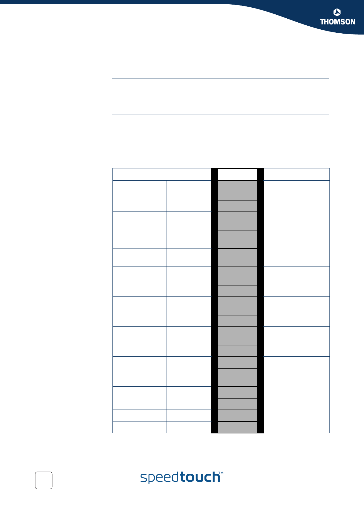
Queues As seen before in “ Mapping to internal class” the SpeedTouch™ supports up to 6
queues. These queues are used to prioritize data. Each queue handles a range of
internal classes. As seen before a packet is associated with an internal class by
means of embedded priority indicators as DSCP, VLAN priority or by defining your
own specific rules.
The table below shows these relations more in detail.
INPUT Mapping OUTPUT
VLAN User
Priority
7 CS6,CS7 15
6
-
-
-
5 AF32,AF33
-
4 AF22,AF23
-
3 AF12,AF13
--5
DiffServ
DSCP
EF
CS5
AF41
CS4
AF42,AF43
AF31
CS3
AF21
CS2
AF11
CS1
Internal
Class
14
13
12
11
10
9
8
7
6
Queue Default
Label
5 Real Time
4WFQ4
3WFQ3
2WFQ2
1WFQ1
60
0
--3
2-2
--1
1-0
CS0
Best Effort
4
0
E-NIT-CTC-20041213-0013 v0.5
Best
Effort
Page 63
Meters, queues and IPQoS
6.2 The IPQoS command group
Overview The queues,meters and EF timers can be configured through the IPQoS command
group. The IPQoS command group contains the following commands and sub groups
:
IPQoS command group
ipqos ef
meter
queue
config
list
Chapter 6
EF command group
ef config
list
stats
meter command group
meter add
config
delete
list
start
stop
flush
stats
clear
E-NIT-CTC-20041213-0013 v0.5
61
Page 64

Chapter 6
Meters, queues and IPQoS
queue command group
queue config
list
stats
clear
62
E-NIT-CTC-20041213-0013 v0.5
Page 65

Chapter 6
Meters, queues and IPQoS
E-NIT-CTC-20041213-0013 v0.5
63
Page 66

Chapter 6
Meters, queues and IPQoS
64
E-NIT-CTC-20041213-0013 v0.5
Page 67
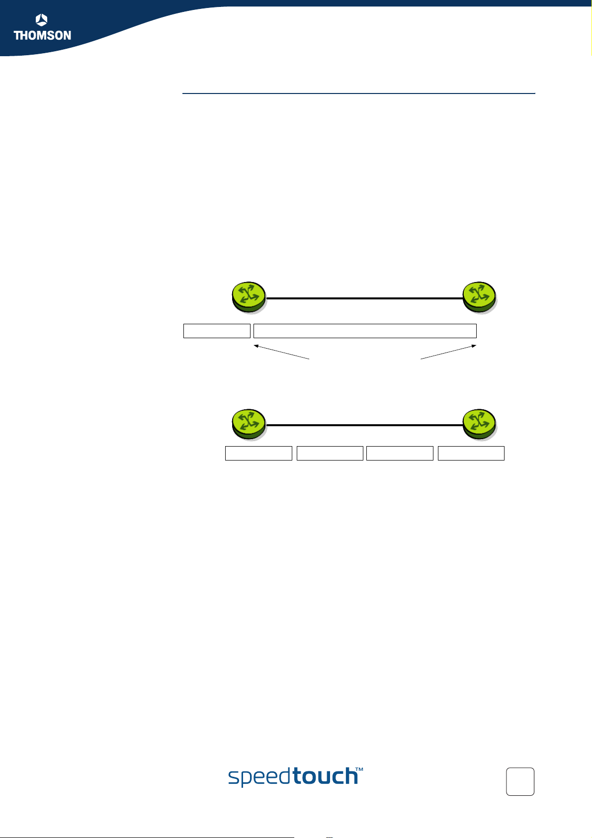
Chapter 6
Meters, queues and IPQoS
MTU explained. In this section we will have a closer look at the MTU values and what exactly does it
do.
Sometimes it might be usefull to lower the MTU of a link when EF data is to be sent.
The reason is that, even if an EF packet gets top priority, it might still get stuck
behind a large data packet that has just started to go out.
The MTU typically needs to be changed on links with a slow uplink (<128Kb/s). The
MTU is set to 1500 bytes by default.
If a default packet of 1500 bytes, is send over a 64Kb link, it takes 18ms before it is
send completly. This could cause delay/jitter for time sensitive data like voice. This is
called serialization delay. By decreasing the MTU, IP packets (with a normal lenght
of 1500 bytes) will be fragmented in smaller packets to meet the defined MTU size.
The example below can illustrate this:
The problem : A voice-packet gets highest priority but gets stuck
behind a large data -packet that is being sent out.
Real time MTU
Elastic Traffic MTU
214 ms transfer time for 1500 byte frame
at 56kbps
The solution: fragment packets when EF exists
Elastic MTU Rea l time MTU Real time MTUElastic MTU
E-NIT-CTC-20041213-0013 v0.5
65
Page 68

Chapter 6
Meters, queues and IPQoS
The table below shows the delay a packet can experience depending on the MTU and
link speed.
MTU
56
kb/s
64
kb/s
128
kb/s
256
kb/s
Line Speed
512
kb/s
768
kbps
64
Bytes
9ms 18ms 36ms 72ms 144ms 214ms
8ms 16ms 32ms 64ms 128ms 187ms
4ms 8ms 16ms 32ms 64ms 93ms
2ms 4ms 8ms 16ms 32ms 48ms
1ms 2ms 4ms 8ms 16ms 23ms
640µse
c
128
Bytes
256
Bytes
512
Bytes
1024
Bytes
1.2ms 2.6ms 5ms 10ms 15ms
The higher the MTU the higher the delay will be. Also the lower the bandwidth the
higher the delay.
EF stats command The ef stats command is used to display the statistics of the ef meter.
The output of this command will look like this :
1500
Bytes
{Administrator}=>:ipqos ef stats
Interface State Remain
(ms)
loop disabled 0
Internet disabled 0
lan1 disabled 0
EF list command The ef list command displays all the ef meters configured.
The output of this command will look like this:
{Administrator}=>:ipqos ef list
Interface State Timeout MTU
(ms) (bytes)
loop disabled 1000 65535
Internet disabled 1000 1500
lan1 disabled 1000 1500
66
E-NIT-CTC-20041213-0013 v0.5
Page 69

Meters, queues and IPQoS
6.4 Meter command group
Introduction The meter command group is used to configure rate limiting. This allows aggregated
data to be policed to pre-configured bandwidths. This rate limiting can be configured
for a specific interface, ip address or service. A meter can be selected by a label or
can be interface specific. In case the meter is configured for a specific interface no
label is needed. Data in excess of the configured parameters will be discarded or
optinally re-marked to a lower priority.
Adding a meter Execute the following CLI command to add a meter:
{Administrator}=>:ipqos meter add name my_meter
This command will add a meter with the name “my_meter”.
Subsequently we need to configure the meter parameters. The section below shows
and explains the different parameters needed to configure a meter.
Chapter 6
E-NIT-CTC-20041213-0013 v0.5
67
Page 70

Chapter 6
Meters, queues and IPQoS
Meter parameters The table below shows all the parameters that can be configured by using the
6.4.1 Meter config command
meter config command.
Parameter Description
name The name of the IPQoS meter.
label The name of the label.
intf The name of the interface.
droprate The drop rate in kilobits per second (Kb/s).
markrate The mark rate in kilobits per second (Kb/s).
burst The burst size in kilobytes (KB).
dropaction The drop action.
Meter config
parameters explained
Name
Label
markaction The mark action.
tosmarking Enable tos marking for marked packets.
tos The type of service used for tos marking.
dscp The diffserv code point (part of tos, used for tos-marking).
precedence The precedence (part of tos, used for tos-marking).
classification The type of classification for marked packets.
class The class or offset used for classification.
In this section we will explian the meter parameters in detail and how to configure a
meter.
name value Description
string This is the name of the IPQoS meter.
68
label value Description
BE, DSCP, EF,
Interactive,
Management, etc
The label to which the meter applies.
E-NIT-CTC-20041213-0013 v0.5
Page 71

Intf
Chapter 6
Meters, queues and IPQoS
intf value Description
Droprate
Markrate
Burst
loop, ipoa1, pppoe,
pppoa, LocalNetwork
droprate value Description
number (0..102400) The drop rate in kilobits per second (Kb/s). Packets in
markrate value Description
number (0..102400) The mark rate in kilobits per second (Kb/s). Packets in
The interface to which the meter applies.
excess of this value will be dropped or counted
depending on the drop action.
excess of this value will be marked or counted
depending on the mark action.
burst value Description
number (0..64) The burst size in kilobytes (KB).
Rate limiting is done by means of a token bucket. A token bucket is a formal
definition of a rate of transfer. It has three components: a burst size, a drop rate, and
a time interval.
Here are some definitions of these terms:
Drop rate:
Specifies how much data can be sent or forwarded per unit time on average.
Burst size:
Specifies in bits (or bytes) per burst how much traffic can be sent within a
given unit of time to not create scheduling concerns.
Time interval:
Specifies the time quantum in seconds per burst. This parameter can not be
changed or defined by the user.
In the token bucket metaphor, tokens are put into the bucket at a certain rate. The
bucket itself has a specified capacity. If the bucket fills to capacity, newly arriving
tokens are discarded. Each token is a permission for the source to send a certain
number of bits into the network. To send a packet, the regulator must remove from
the bucket a number of tokens equal in representation to the packet size.
If not enough tokens are in the bucket to send a packet, the packet either waits until
the bucket has enough tokens or the packet is dropped or marked down.
E-NIT-CTC-20041213-0013 v0.5
69
Page 72

Chapter 6
Meters, queues and IPQoS
Page 73

Dscp
Chapter 6
Meters, queues and IPQoS
dscp value Description
Precedence
ef, af11, af12, af13,
af21, af22, af23, af31,
af32, af33, af41, af42,
af43, cs0, cs1, cs2,
cs3, cs4, cs5, cs6, cs7
or a number
precedence value Description
routine will set the precedence bits to 000. (lowest
priority will set the precedence bits to 001.
immediate will set the precedence bits to 010.
flash will set the precedence bits to 011.
flash-override will set the precedence bits to 100.
CRITIC-ECP will set the precedence bits to 101.
internetwork-control will set the precedence bits to 110.
network-control will set the precedence bits to 111. (highest priority)
The diffserv code point value to be set.
priority)
Classification
Class
number 0..7 0..7.
classification value Description
ignore No changes are made to the classification.
overwrite The internal priority will be overwritten, no matter
what is the value is.
decrease The internal priority will only be overwritten if the
value defined is lower than the value upon arrival.
offset This will lower the priority setting with a relative
offset. The offset value is defined in the class value.
class value description
number (0..15) The class or offset used for classification.
E-NIT-CTC-20041213-0013 v0.5
71
Page 74

Chapter 6
Meters, queues and IPQoS
Meter delete command The delete command is used to delete a meter from the meters list.
Meter list command The list command will display a list of all meters configured.
For example: the following CLI command will delete the meter with name “test2”
from the meter list.
{Administrator}=>:ipqos meter delete name my_meter
{Administrator}=>:ipqos meter list
The output could look something like this :
my_meter [STOPPED]: LABEL: INTF:
DROP : droprate : 102400kbps burst: 64KB action: drop
MARK : markrate : 102400kbps burst: 64KB action: count
tosmarking : enabled type : tos tos : 0
classification: decrease class: 0
The meter listed above is not active as it’s state is [STOPPED]
Meter start command By using the start command a meter can be activated.
For example: the command below will start the meter with name “my-meter”
{Administrator}=>:ipqos meter start name my_meter
If no start command is given the meter will not be active and rate limiting will not
occur.
To check if the meter is running or not you can use the list command.
{Administrator}=>:ipqos meter list
my_meter [STARTED]: LABEL: INTF:
DROP : droprate : 102400kbps burst: 64KB action: drop
MARK : markrate : 102400kbps burst: 64KB action: count
tosmarking : enabled type : tos tos : 0
classification: decrease class: 0
Notice that the meter listed above is now active as it’s state is [STARTED]
72
E-NIT-CTC-20041213-0013 v0.5
Page 75
Meters, queues and IPQoS
Meter stop command By using the stop command a meter can be deactivated.
For example: the command below will stop the meter with name “my_meter”
{Administrator}=>:ipqos meter stop name my_meter
To check if the meter is stopped or not you can use the list command.
{Administrator}=>:ipqos meter list
my_meter [STOPPED]: LABEL: INTF:
DROP : droprate : 102400kbps burst: 64KB action: drop
MARK : markrate : 102400kbps burst: 64KB action: count
tosmarking : enabled type : tos tos : 0
classification: decrease class: 0
The meter listed above is now in-active as it’s state is [STOPPED]
Meter flush command The flush command can be used to delete all meters defined by a single command.
For example: the command below will delete all meters defined.
Chapter 6
{Administrator}=>:ipqos meter flush
Meter stats command To view the meter statistics ( number of packets dropped / marked) the stats
command can be used.
For example: the command below will show the statistics for the meters defined.
{Administrator}=>:ipqos meter stats
The output of this command will look like this:
Name # packets # packets # packets
accepted dropped marked
test2 75 5 40
Execute following command to clear the stats counters:
{Administrator}=>:ipqos meter clear
This command will reset the stats meters
Name # packets # packets # packets
accepted dropped marked
test2 0 0 0
E-NIT-CTC-20041213-0013 v0.5
73
Page 76

Chapter 6
Meters, queues and IPQoS
6.4.2 Packet flow
Illustration The figure below illustrates the packet flow in case label based metering is used.
Packet
Data
1
MeterClassification Meter
no
LAN
Stage Description
Classification
Metering
yes
2
Action
Action
queue
Drop
Packet is
dropped
3
Mark
no
no
Classification
yes
4
Set Clas s
6
Queue
scheduling
7
ATM Q oS
WAN
yes
Drop
no
Mark Tos marking Set tos byte
no
5
Count
yes yes
Count
Map class to
1 A packet arrives in the resource management module and gets
classified based upon a rule set. The packet gets a label assigned.
In case the label refers to a meter the packet gets forwarded to the
meter module. If not, the packet is forwarded back to the LAN or to
the WAN after queuing and scheduling.
2 Packets in excess of the drop rate will be dropped or counted
depending on the settings of the dropaction parameter.
3 If the mark rate is exceeded the packet will be marked or counted
depending on the settings of the markaction parameter. If a packet is
marked, the tos byte can be set or the internal class can be changed.
If classification has been enabled the internal class will be set.
4 The class is set. This will place packets in a specified queue.
5 Based upon the destination (LAN/WAN) the packet gets forwarded to
the proper interface.
6 In case the packet will be sent out to the WAN side, the packet gets
assigned to the corresponding queue.
7 Finally the ATMQoS parameters are taken into account and the
packet is ready to be sent to the WAN.
74
E-NIT-CTC-20041213-0013 v0.5
Page 77

Chapter 6
Meters, queues and IPQoS
6.5 Queue command group
Introduction With the queue command group the queues can be individually configured.
Parameters like queue propagation, ENC marking and queue size can be defined here.
The parameters that can be configured through this command group are mainly used
for advanced tuning of the queues.
Queue config command As seen before, the SpeedTouch™ has 6 build-in queues per ATM interface . These
queues are pre-defined. The following parameters can be modified by using the
config command in the queue subgroup :
Parameter Description
dest The name of the interface of which you want to change the
parameters. Typically, a phonebook entry.
queue The number of the subqueue.
propagate Propagate the packets in lower priority queue instead of
dropping them.
ecnmarking Enable Explicit Congestion Notification for IP packets in this
subqueue.
ackfiltering Enable filtering of TCP ACK packets.
maxpackets The maximum number of packets in the subqueue.
maxbytes The maximum subqueue size in kilo bytes (KB).
respacktes The reserved number of packets in the subqueue.
resbytes The reserved subqueue size in kilo bytes (KB).
hold The hold time in micro-seconds for early discard strategy.
markprob The maximum packet marking probability in parts per mille for
early discard strategy.
E-NIT-CTC-20041213-0013 v0.5
75
Page 78

Chapter 6
Meters, queues and IPQoS
6.5.1 Queue config parameters explained
In this section we will have a closer look at the different parameters and their values.
Dest
dest value Description
phonebook entry The name of the interface you want to configure.
Queue
queue value Description
number (0..5) The number of the subqueue you want to configure,
where 0 is the best effort queue and 5 is the real time
(EF) queue
Propagate
Ecnmarking
propagate value Description
enabled If the propagate function is enabled an overflow to a
lower priority queue will created in case the initial
queue is full.
disabled If the propagate function is disabled packets in excess
of the queue size will be dropped.
ecnmarking value Description
enabled If the encmarking function is enabled the congestion
Experienced (CE) codepoint in the ECN field is set. This
means that when a queue is congested the EC
codepoint will be set instead of dropping the packet.
disabled If the encmarking is disabled packets will be dropped if
the queue is congested.
76
E-NIT-CTC-20041213-0013 v0.5
Page 79

Ackfiltering
Chapter 6
Meters, queues and IPQoS
ackfiltering value Description
enabled If the ackfiltering option is enabled duplicate ACK
packets in a queue will only be sent once. Meaning
that the last duplicate ACK packet will be sent and the
other ACK packets will be dropped
disabled If the ackfiltering option is disabled all ACK packets
will be sent in their original sequence.
Example
The figure below illustrates how ack filtering is done.
Data ACK1Data DataACK2
An upload data stream is exists (data packets). Meanwhile a download TCP
connection is generated as well. TCP-based downloads can only continue if the
remote site receives ACK packets for each data packet it sends. As we can see in
the figure above there are two ACK packets in the queue. To avoid delay we will only
send the second ACK packet and drop the first ACK packet. If the remote site
receives ACK2 it will know that everything that was sent before was OK. If ACK
filtering is turned off both the ACK will be send, causing delay.
ACK filtering happens on a per TCP-connection base.
E-NIT-CTC-20041213-0013 v0.5
77
Page 80

Chapter 6
Meters, queues and IPQoS
Maxpackets
maxpackets value Description
number (0..255) The maximum number of packets in the subqueue.
As we will see further on there is a maxpackets parameter in the IPQoS settings
which sets the max number of packets that can be placed in all queues (0..5) at one
time. If the maxpackets parameter for each seperate queue is set to 100 this would
mean that the maximum number of packets in that queue would be 100. If this is set
for the 5 queues this would mean that a total of 500 packets could be placed in the
queues.
The maxpackets value can not be more than 250, so we could never place 500
packets in the queues. For example:
The total size for queuing is 250 packets.(IP QoS maxpackets)
Each of the 6 queues can hold a maximum of 100 packets. (queue maxpackets)
Each of the 6 queues has 13 packets reserved incase they are empty. (queue
respackets)
The rest of the total size (250-(6*13)) will be used by means of priority.
If 100 packets are placed in the EF queue this would leave us with 98 packets that
can still be placed in an other queue.
250 (maxpackets) -100 (EF queue)=150
150 - (5*13respackets)=85 packets that can be place in a queue
The total number of packets that can still be placed in 1 queue will now be
85+13=98
100(EF)+98+(4*13)=250
This is used to avoid queue starvation. If no reserved packets would be defined, one
queue could use up all availlable queue space.
Maxbytes
Respackets
maxbytes value Description
number (0..64) The maximum size in kilo bytes (KB) of the subqueue.
respackets value Description
number (0..250) The reserved number of packets in the subqueue. This
is the space reserved in the subqueue to allow
packets.
78
E-NIT-CTC-20041213-0013 v0.5
Page 81

Resbytes
Hold
Chapter 6
Meters, queues and IPQoS
resbytes value Description
number (0..64) The reserved subqueue size in kilo bytes (KB).
This has the same function as the respackets
parameter but uses size in kilo bytes instead of
packets.
hold value Description
number The hold time in microseconds for early discard
strategy.
Markprob
markprob value Description
number (0..1000) The maximum packet marking probability in parts per
mille for early discard strategy.
The early discard strategy will calculate the drop probability based on the BLUE
algorithm, which uses packet loss and link utilization history to manage congestion.
BLUE maintains a single probability, which it uses to mark (or drop) packets when
they are queued. If the queue is continually dropping packets due to buffer overflow,
BLUE increments the marking probability, thus increasing the rate at which it sends
back congestion notification. Conversely, if the queue becomes empty or if the link is
idle, BLUE decreases its marking probability.
E-NIT-CTC-20041213-0013 v0.5
79
Page 82

Chapter 6
Meters, queues and IPQoS
Queue list command The list command will show you a listing of all queues and their configuration
settings.
This command can be refined by adding the dest parameter. This way only the
queues of one ATM interface can be shown.
For example:
{Administrator}=>:ipqos queue list
This will give you an output like this:
{Administrator}=>:ipqos queue list
Name Queue Propagate ECN AckFilter Size Size Reserved Reserved Holdtime Markprob
(Packets) (KBytes) (Packets) (KBytes) (usecs)
atm_pvc_0_35 0 disabled disabled 100 20 13 4 50000 1000
1 disabled disabled disabled 100 20 13 4 50000 1000
2 disabled disabled disabled 100 20 13 4 50000 1000
3 disabled disabled disabled 100 20 13 4 50000 1000
4 disabled disabled disabled 100 20 13 4 50000 1000
5 disabled disabled disabled 0 0 30 12 50000 1000
atm_pvc_8_35 0 disabled disabled 100 20 13 4 50000 1000
1 disabled disabled disabled 100 20 13 4 50000 1000
2 disabled disabled disabled 100 20 13 4 50000 1000
3 disabled disabled disabled 100 20 13 4 50000 1000
4 disabled disabled disabled 100 20 13 4 50000 1000
5 disabled disabled disabled 0 0 30 12 50000 1000
The example below shows the same command with the use of the dest parameter.
{Administrator}=>:ipqos queue list dest atm_pvc_0_35
Name Queue Propagate ECN AckFilter Size Size Reserved Reserved Holdtime Markprob
(Packets) (KBytes) (Packets) (KBytes) (usecs)
atm_pvc_0_35 0 disabled disabled 100 20 13 4 50000 1000
1 disabled disabled disabled 100 20 13 4 50000 1000
2 disabled disabled disabled 100 20 13 4 50000 1000
3 disabled disabled disabled 100 20 13 4 50000 1000
4 disabled disabled disabled 100 20 13 4 50000 1000
5 disabled disabled disabled 0 0 30 12 50000 1000
Queue stats command The stats command will show you the statistics of the queues.
For example:
{Administrator}=>:ipqos queue stats
This will give an output like this :
Name Queue # packets # packets # packets # packets # packets Marking
added marked removed dropped replaced
phone1 0 3183 0 3183 0 0 0%
1 0 0 0 0 0 0%
2 54 0 54 0 0 0%
3 0 0 0 0 0 0%
4 52 0 52 0 0 0%
5 1398 0 1398 0 0 0%
Queue clear command The clear command, resets the counters of the queue stats command.
{Administrator}=>:ipqos queue clear
80
E-NIT-CTC-20041213-0013 v0.5
Page 83

Meters, queues and IPQoS
6.6 IPQoS Command group
Introduction The IPQoS command group is used to configure the common parameters for a set of
queues instantiaded per interface.
ipqos config command The following parameters can be configured in the IPQoS command group:
Parameter Description
dest The name of the interface of which you want to configure
IPQoS. Typically, a phonebook entry.
state Enable, disable IPQoS for the interface.
discard The packet discard strategy in case of congestion.
priority The subqueue priority algorithm.
realtimerate The percentage of the bandwith.
Chapter 6
burstsize Burst size in kilo bytes (KB).
weight1 The weight of queue 1 used for weighted fair queueing (WFQ)
or weighted round robin (WRR).
weight2 The weight of queue 2 used for weighted fair queueing (WFQ)
or weighted round robin (WRR).
weight3 The weight of queue 3 used for weighted fair queueing (WFQ)
or weighted round robin (WRR).
weight4 The weight of queue 4 used for weighted fair queueing (WFQ)
or weighted round robin (WRR).
maxpackets The maximum number of packets in all queues.
maxbytes The maximum size in kilo bytes (KB) in all queues.
E-NIT-CTC-20041213-0013 v0.5
81
Page 84

Chapter 6
Meters, queues and IPQoS
Introduction In this section we will have a closer look at the different parameters and their values.
6.6.1 Ipqos config parameters explained
Dest
dest value Description
phonebook entry The name of the interface. Typically, a phonebook
entry to which the queues belong.
State
state value Description
enabled This enables IPQoS on the interface
Discard
disabled This disables IPQoS on the interface
The IP QoS policy can only be changed on disconnected (detached)
!
interfaces.
discard value Description
tail In case of tail drop as discard strategy, arriving
packets will be dropped as soon as the destination
queue is in an overflow state.
early In case of early drop as discard strategy, the used
queue management algorithm will be BLUE
82
E-NIT-CTC-20041213-0013 v0.5
Page 85

Priority
Chapter 6
Meters, queues and IPQoS
priority value Description
strict In case strict is selected as scheduling algorithm, each
queue will be served as long as data is present in the
queue. This could mean heavy delay.
WFQ In case WFQ is selected as scheduling algorithm the
queues (WFQ4 .. WFQ1) are being served based upon
weight and time. The higher the weight the higher the
priority. The longer the time a packet spends in the
queue the higher the priority.
WRR In case WRR is selected as scheduling algorithm the
queues (WFQ4 .. WFQ1) are being served based upon
weight only. The higher the weight the higher the
priority.
Realtimerate
Burstsize
realtimerate value Description
number (0..100) The percentage of the available bandwidth that is
allowed to be used to serve the real time queue. If set
to 100 the other queues will not be served in case of
congestion and they will experience starvation.
burstsize value Description
number (1..64) Burst size in kilo bytes (KB).
E-NIT-CTC-20041213-0013 v0.5
83
Page 86

Chapter 6
Meters, queues and IPQoS
Weight
weight1 value Description
number (1..97) Percentage to define the weight of queue 1 used for
weighted fair queuing (WFQ) or weighted round robin
(WRR)
weight2 value Description
number (1..97) Percentage to define the weight of queue 2 used for
weighted fair queuing (WFQ) or weighted round robin
(WRR)
weight3 value Description
number (1..97) Percentage to define the weight of queue 3 used for
weighted fair queuing (WFQ) or weighted round robin
(WRR)
Maxpackets
Maxbytes
Ipqos list command
weight4 value Description
number (1..97) Percentage to define the weight of queue 4 used for
weighted fair queuing (WFQ) or weighted round robin
(WRR)
maxpackets value Description
number (1..250) The maximum number of packets in all queues for this
interface.
maxbytes value Description
number (0..64) The maximum size in kilo bytes (KB) in all queues.
The list command is used to display the ipqos settings configured.
{Administrator}=>:ipqos list
84
This command should give you an output like this :
{Administrator}=>:ipqos list
Name State Discard Priority Size Size Rate Burst Weights
(Packets) (KBytes) (%) (KBytes) Weights
atm_pvc_0_35 enabled early wfq 250 56 80% 2 25% 25% 25% 25%
atm_pvc_8_35 enabled early wfq 250 56 80% 2 25% 25% 25% 25%
Now that we have seen all commands to configure IPQoS we will give a few
examples on how to use the different commands to get to the desired result.
E-NIT-CTC-20041213-0013 v0.5
Page 87

Scenario 1: Residential user.
7 Scenario 1: Residential user.
Introduction In this chapter describes an example of how IP QoS might be used in a typical
residential user scenario.
This user uses the following applications:
A VoIP device that uses Expedited Forwarding (for example the ST190)
A Windows application that uses Assured Forwarding (AF for example
Messenger)
An interactive Windows application (for example Web surfing)
Windows applications that use Best Effort as client (for example peer-to-peer
program) and as server (for example an FTP server).
Expected result In this case the desired behavior is that the EF traffic has strict priority on the AF-
and-interactive traffic, and the AF-and-interactive traffic on the BE traffic. The
desired behavior is also that, even on an asymmetric link like ADSL, the client and
server BE traffic fairly share the available bandwidth.
Chapter 7
Configuration Let’s start with the components needed to configure the quality of service to meet
the requirements above.
We will need 3 labels :
A VoIP label for Voice packets.
A DSCP label for the AF packets.
An Interactive label for Interactive packets.
All other packets will be treated as Best Effort.
We will need a set of rules to assign the labels to the packets.
For voice packets we will need 2 rules, one for SIP and one for H323
For AF packets we will need only one rule.
For Interactive packets we will need a total of 14 rules. (telnet, http,smtp,
pop,ect)
We will need a set of expressions to be used in the rules.
For voice we will need a total of 8 expressions.
For AF we only need 1 expression.
For Interactive we will need a total of 14 expressions.
E-NIT-CTC-20041213-0013 v0.5
85
Page 88

Chapter 7
Scenario 1: Residential user.
Introduction We will now have a closer look at the parameters needed to configure classification
The web interface The SpeedTouch™ can be configured in two way’s:
7.1 Configuring labels and rules for VoIP.
for Voice over IP.
Since voice traffic is very sensitive to delay and jitter we would like to give our voice
traffice absolute priority over all other traffic.
Via the command line interface (CLI)
Via the web interface (GUI)
In this chapter we willl use the GUI to configure the SpeedTouch™, at the end of this
chapter a CLI command list will be given as well.
To enter the GUI open a web browser and surf to the following webpage : http://
192.168.1.254 or http://SpeedTouch
This is the default IP address of the SpeedTouch™.
Labels Go to the classification menu by clicking:
Expert mode -> IP Router -> Classification
Select the Labels tab a list of labels which have been created, if a default
configuration is used.
In this list we can see a label named VoIP.
Packets who get this label assigned will have their internal class set to 14. This
means that these packets will be placed in the Real Time queue. The Real Time
queue is used for traffic with the highest priority. The TCP ack packets will be
treathed with the same priority. TOS Marking for these packets has been disabled.
86
E-NIT-CTC-20041213-0013 v0.5
Page 89

Chapter 7
Scenario 1: Residential user.
Rules Select the IP QoS Rules tab to define one or more rules to get this label assigned to
the proper packets.
By default only the user defined IP QoS rules are shown. To see the default IP QoS
rules click expand
In the list that is now shown you will see two rules with label name VoI P.
The first rule has index 2 and service sip. It applies to all traffic from any Interface
with any IP address to any IP address.
The second rule has index 3 and service h232. It applies to all traffic from any
Interface with any IP address to any IP address.
The services SIP and H232 are defined in the expressions page.
E-NIT-CTC-20041213-0013 v0.5
87
Page 90
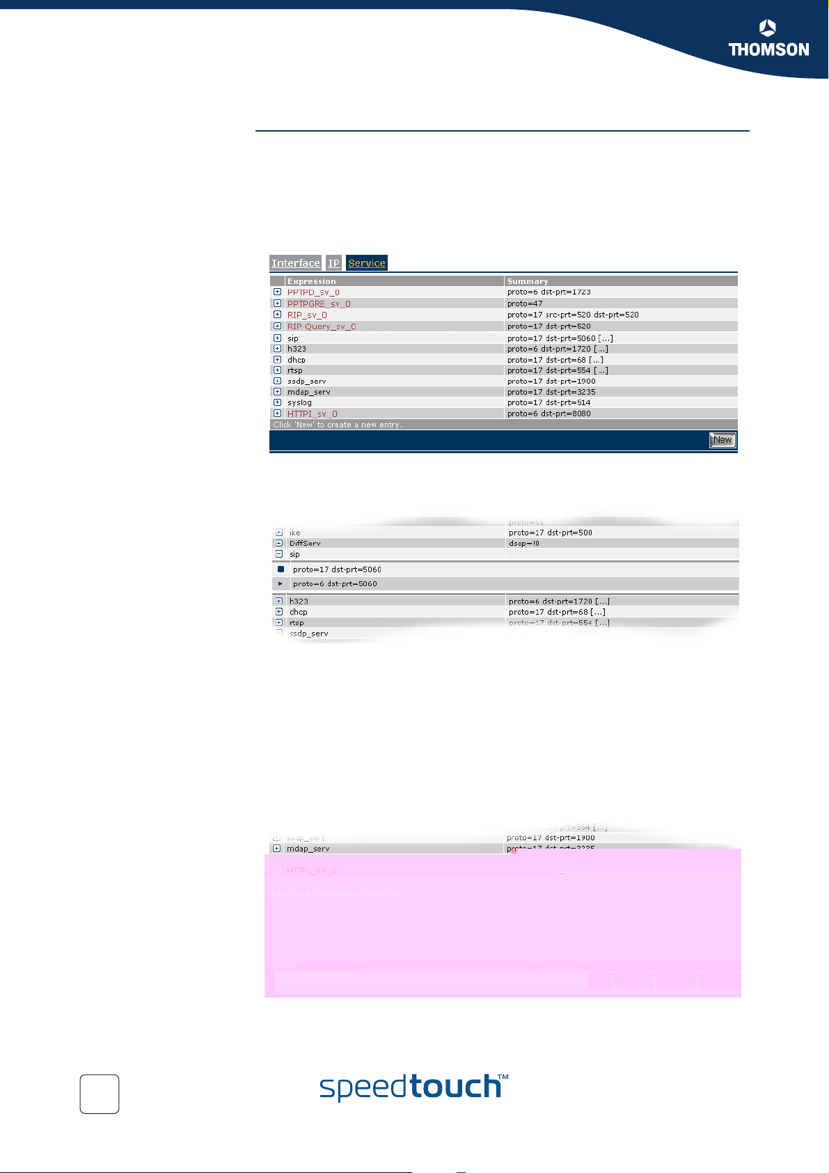
Chapter 7
Scenario 1: Residential user.
Expressions We will now have a look at these two expressions. Therefore go to the expression
page and select the service tab.
Expert mode -> IP Router -> Expressions
This will show you a list of service expressions which have been created, if a default
configuration is used.
When we click on the + next to the SIP expression we can see the definitions used
for this expression.
Here we can see that the expression SIP is used for packets :
of type UDP (proto=17) with destination port 5060.
of type TCP (proto=6) with destination port 5060.
These two expressions define the protocol and ports used by SIP.
Meaning that when UDP traffic on port 5060 is transmitted the SpeedTouch™ knows
that this is SIP traffic. This also applies for TCP traffic on port 5060.
At the bottom of the page you can see the actual protocol instead of the number.
88
E-NIT-CTC-20041213-0013 v0.5
Page 91
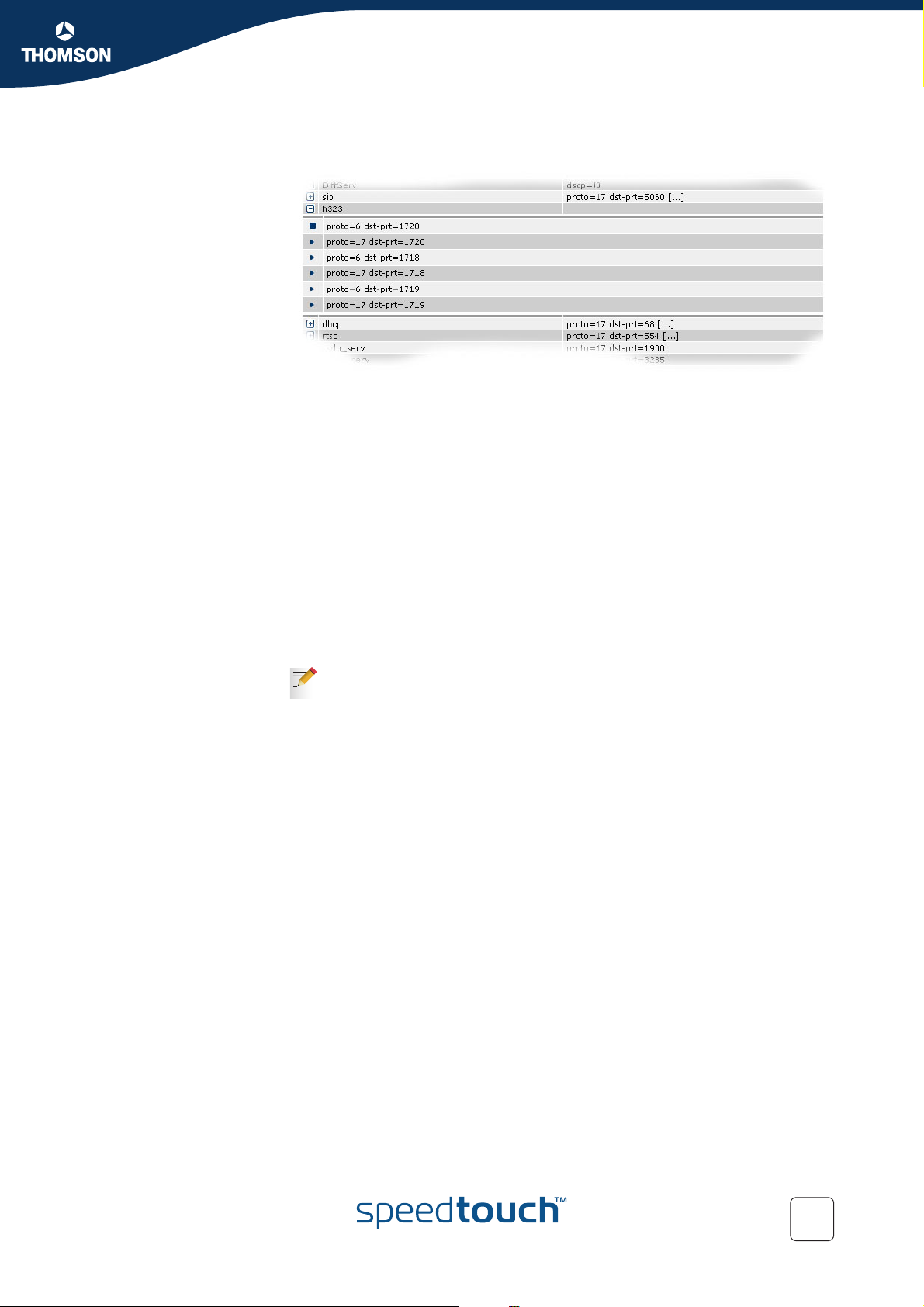
Chapter 7
Scenario 1: Residential user.
When we click on the + next to the H323 expression we can see the definitions used
for this expression.
Here we can see that the expression h323 is used for packets :
of the type TCP (proto=6) with destination port 1720.
of the type UDP (proto=17) with destination port 1720.
of the type TCP (proto=6) with destination port 1718.
of the type UDP (proto=17) with destination port 1718.
of the type TCP (proto=6) with destination port 1719.
of the type UDP (proto=17) with destination port 1719.
These six expressions define the protocol and ports used by H323.
Meaning that when TCP traffic on port 1720 is transmitted the SpeedTouch™ knows
that this is H323 traffic. This also applies for UDP traffic on port 1720. By defining
these expressions we help the SpeedTouch™ to determine the service used.
Again at the bottom of the page you can see the actual protocol instead of the
number.
These are all parameters needed to enable classification for VoIP. The actual
Quality of Service is defined later on.
E-NIT-CTC-20041213-0013 v0.5
89
Page 92

Chapter 7
Scenario 1: Residential user.
Introduction We will now have a closer look at the parameters needed to configure classification
7.2 Configuring labels and rules for DSCP.
for packets with DSCP set.
Labels Go to the classification menu and select the Labels tab.
Expert mode -> IP Router -> Classification
You will now see a list of labels which have been created, if a default configuration is
used.
In this list we can see a label named DSCP.
Packets who get this label assigned will have their internal class set to the class that
matches with the DSCP setting (see “ Mapping to internal class” on page 28). This
means that these packets will be placed in the queue matching the DSCP setting.
The TCP ack packets will be treated with the same priority. TOS Marking for these
packets has been disabled.
Rules Go to the classification menu and select the IP QoS tab.
Expert mode -> IP Router -> Classification
Here we have to define one or more rules to get this label assigned to the proper
packets.
In this screen you will see the user defined IP QoS rules, to see the default IP QoS
rules click expand.
90
In the list that is now shown you will see one rule with label name DSCP.
This rule has index 1 and service DiffServ. It applies to all traffic from any Interface
with any IP address to any IP address.
The service DiffServ is defined in the expressions page.
E-NIT-CTC-20041213-0013 v0.5
Page 93

Chapter 7
Scenario 1: Residential user.
Expressions We will now have a look at this expression. Therefore go to the expression page and
select the Service tab:
Expert mode -> IP Router -> Expressions
This will show you a list of service expressions defined, if a default configuration is
used.
When we click on the + next to the DiffServ expression name we can see the
definitions used for this expression.
Here we can see that the expression DiffServ is used for packets:
with the dscp set to a value different from 0. (dscp=!0)
The ! sign means that the value is allowed to be anything but 0.
These are all parameters needed to enable classification for packets with
DSCP set. The actual Quality of service is defined later on.
E-NIT-CTC-20041213-0013 v0.5
91
Page 94
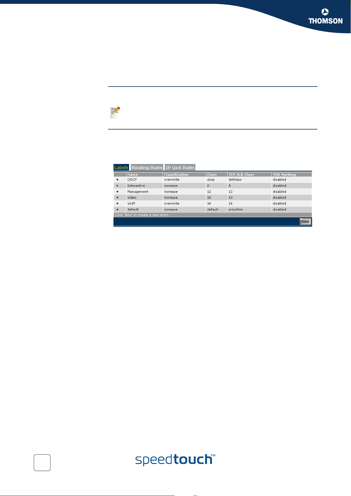
Chapter 7
Scenario 1: Residential user.
Introduction We will now have a closer look at the parameters needed to configure classification
7.3 Configuring labels and rules for Interactive traffic.
for interactive traffic.
With interactive traffic we mean traffic like websurfing, e-mail,telnet etc.
Labels Go to the classification menu an select the Labels tab:
Expert mode -> IP Router -> Classification
You will now see a list of labels which have been created by default.
In this list we can see a label named Interactive.
Packets who get this label assigned will have their internal class set to 8. This means
that these packets will be placed in the WFQ2 queue (see “ Mapping to internal
class” on page 28). The TCP ack packets will be treated with the same priority. TOS
Marking for these packets has been disabled.
92
E-NIT-CTC-20041213-0013 v0.5
Page 95

Chapter 7
Scenario 1: Residential user.
E-NIT-CTC-20041213-0013 v0.5
93
Page 96

Chapter 7
Scenario 1: Residential user.
Expressions We will now have a look at the http expression. Go to the expression page and select
the Service tab.
Expert mode -> IP Router -> Expressions
This will show you a list of service expressions defined by default.
When we click on the + next to the HTTP expression name we can see the
definitions used for this expression.
Here we can see that the expression http is used for packets :
of the type TCP (proto=6) with destination port 80.
Again at the bottom of the page you can see the actual protocol instead of the
number.
If desired you can have a look at all the different expressions used for interactive
traffic. We will not discuss all the expressions here as the configuration principle is
the same for all of them. They all define a protocol and a port used by the service.
94
E-NIT-CTC-20041213-0013 v0.5
Page 97

Chapter 7
Scenario 1: Residential user.
E-NIT-CTC-20041213-0013 v0.5
95
Page 98

Chapter 7
Scenario 1: Residential user.
IP QoS queues Go to the IP QoS menu and select the Queues tab.
Expert mode -> IP Router -> IP QoS
This section on the IPQoS page is used to configure propagation of the queues, ECN
marking and ACK filtering.
We do not use propagation, ECN marking or ACK filtering in this scenario.
This concludes the configuration of IP QoS for a typical residential user.
96
E-NIT-CTC-20041213-0013 v0.5
Page 99

Chapter 8
Scenario 2: Business user with TOS marking.
8 Scenario 2: Business user with TOS marking.
Introduction In this chapter we will explain on how IP QoS for a business user can be configured.
In our example we will use the following configuration:
On the LAN three groups of devices "Gold", "Silver" and "Bronze".
Some Expedited Forwarding applications.
The CPE is remotely managed.
The CPE is the trusted edge device and performs the TOS/DiffServ marking for
the Gold, Silver, Bronze and Remote Management traffic.
Expected result In this case the desired behavior is that the EF traffic has strict priority over all the
other traffic, but with an overflow to a lower priority queue in case the EF traffic
exceeds 50 percentage of the available upstream bandwidth.
Weigthed fair queuing is used between the Remote Management, the Gold and the
Silver traffic; this traffic is AF marked by the CPE.
The Bronze traffic is BE marked by the CPE and gets lower priority than all other
traffic.
E-NIT-CTC-20041213-0013 v0.5
97
Page 100
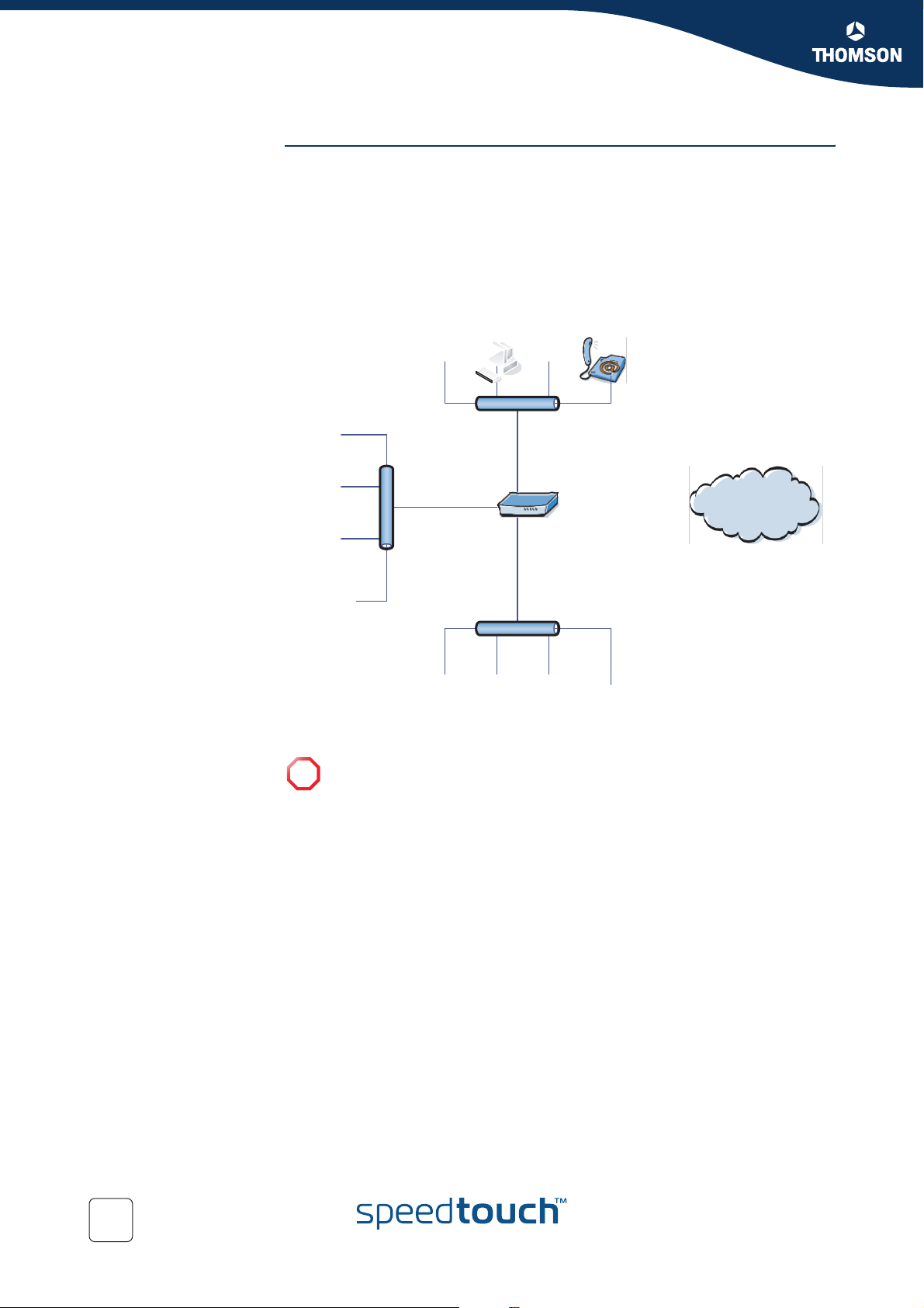
Chapter 8
Scenario 2: Business user with TOS marking.
Configuration The illustration below helps us to visualise e the setup.
We will use three different LAN segements.
1 The “GOLD” segment using IP adresses in the range of 10.0.0.0/24.
2 The “SILVER”segment using IP adresses in the range of 11.0.0.0/24.
3 The “BRONZE” segment using IP adresses in the range of 12.0.0.0/24.
We will assume that these three segments are already configured on the
SpeedTouch™ (for more information see “SpeedTouch™ user’s guide”.
All three groups have voice services.
!
INTE RNET
98
E-NIT-CTC-20041213-0013 v0.5
 Loading...