

Page 1
Page 2
5iFlE'_
RADIO
CORPORATION
OF
AMERICA
I
•
ELECTRONIC
DATA
PROCESSING
SYSTEM
7C25i
TRAINING
~RADIO
CORPORATION
70-25-801
MANUAL
o F
AMERICA
Page 3
The
information
is
subject
Revisions
of
such
First
Printing:
Second
to
change
may
changes
Printing:
contained
without
be
issued
and/or
to
additions.
December, 1964
January,
herein
notice.
advise
1965
Page 4
TABLE OF CONTENTS
Page
General
Description
High-Speed
Introduction
HSM
Hexadecimal
Exercise
Data
and
Instruction
Data
Unpacked
Edited
Machine
Exercise
Interrupt
Introduction
Programming
Processing
Interrupt
Types
I/O
Interrupt
Operation
Arithmetic
Elapsed
Inhibiting
Exercise
Summary
. . . . • • • • • . . . • . • . • • . • . • . . • • • . • • • • • . • . . • • • • . • . . . . • • . • . . 1
Memory
• • . • . . . • • • • . • . • • . • . • . • . • . • . . • • • . • • . • • • . • • • • • • . . . • • • • • • 3
.••..•.•••...•.•....•.•.••.•..•••..•..••••••..••••••.•..
Addressing
..••••••..•.•••••.••.••.•.•.•.•..•.••.•..••.•••...•..
Numbering
System
• . . • • • . • . . • . • . . • • • . • . • • • • . • • • • . . • • • . . • • • • • • 4
.••••••......•.•.•.•.••••••.•.•.••••••.•••••••••..•.•..•••
Formats
Format
Format
Instruction
Format
. . . . • . • . • . • . • • • • • . • . • • . • • • • • • • • • • • • . • . • • • • • • • • • • . • • • • . • 6
.•.•...••••••......•..•..•••..•.•..•.•.•••.•.•.••.••••
........•.•.••.•••••.•.•..•.•••••..•.•.••••...••
.•.•..•••••••••.•.•••••••.••••.••••.••••.••.••••.•••
Format
•.•...••.••••••••...••.••.•.••.•.•.••....••••
.•••.•..•.•..••..••••••••••••.••••••••.•..•.••••••..••••.•
.••..•.•..•••.•.••.••••.••••.•.....••.•••..••••••.•.••.••.•.•
••.•.•.•..•••....•.•.•..•..•..•.•.....••.•.••..••••..•..
State
of
Interrupt
Code
Timer
Interrupt
States.
State
• . • . • . • • • . . . • . . . . . . • • • • • • . • . • . . • • . • • . . • • • • . • • . . . • • • • • . • 9
•.
Overflow
. . • . • • • . • • . • . • . • . • . • • • . • • • • . • • . • . • • . • • • • • • . • • • • • • • 9
. . . . . . . . • . . . . . . • . . . . • • • . • . • . . • . . . . . . . . . . . • . . . . . . . • . • • 9
. • • . • • . . . . . . . • . • . • . . . . • . . . . . . . . . . . • • • • • • . • . . • . . • . . . • 9
. . • • • . . • • • • • • . • . • . • • . • • • • • . . • . • . . . . . . • • . • . • . • . • . . • . • • 9
Trap
.•...•••••.•.•.•••••••........•..••.....•........•
and
Divide
Interrupt.
Exception
. . . . . • . • . . . . . • . • . . . . . . . • . . . . . . . . . . . .
. . . . . • . • . . . • . . . . . . . . . • . • . . . . • . . . • • • • • . . . . . . . • . . 11
•••..•••.••.•..•.•..••....•...•....•.•••......•....
...•....•.............•.................•......•...•....•.
of
Interrupt
Logic
..•..•..•.•...•...•.•......••.•....•..•......
3
3
5
6
6
6
7
7
9
9
10
10
11
11
12
Elapsed
Time
Introduction
Format
Addressing
Self-Defining
Expressions
Implied
Assembler
Define
Origin
Constant
Program
Run
Equate
Base
Extended
Exercise
Clock.
to
the
Requirements
• • • • . • • • • • • • . • • • . • • • . . • . • . • . • • • . • • • . • • • • • • . . . • . • • • • . .
RCA
70/25
Assembly
Language . ..•
• • • . • . • • • . • . • • • . • • • . • . . • • . • • •
•••.•.•••.•.•••.•.•••...•••.••••.•••.••.•..••••..
. . • • • • . • • . • • • • . • • • . . • • • . • . • . • • • • • . • . . • . • • • . • • • • • • . • • • . • • •
Values
•••••.••••.•••••.•.•.•••.••.••••.•••••••••.•..•.•.
• . • • • . • . • • • • • • • . . • • • . . . • . • . • . • . • • • • • . . • . • • • • • • • • • . • • • • . . 16
Lengths
and
Register
..........•.•.•.....•..•...•.•......•.•.•...•.....•.•
Controlling
Storage
Code
Definition
Linking
Segment
Code
Mnemonic
Codes
(DS)
•.••.•••..••••••••.•...•••.••••...••••..•••.
.•.•.•.••..•.•.•••••••.•.••••.••••••••.•..•.•.••
(ORG) • . • . . . • . • . • . . • • . • • . . . . . . . • • . . • . • . • • . . • . . • . . . . . . • •
(DC)
Codes
Controlling
(EQU)
Controlling
Instructions
...•.•.•...•.••.••.•.....••...
(ENTRY
and
Codes
EXTRH)
(START,
.•.•.•........
END,
....•....•.........•........•..•.....•.......•••
Codes
(USING, DROP)
.........•..................
. • . . . • . • . • . • • . . • . • . . . . . . . . . . . • . . • • . • . . . •
CSECT)
. . . . . . . . . . . . . . . . • . . 20
0 • • • • • • • • • • • • • •
0 • • • • • • • • • • • • • • •
.....•.•.•.•.......•...•......•.........•.................
13
14
14
14
16
17
17
18
18
18
19
21
21
21
22
Page 5
TABLE
OF
CONTENTS
(Continued)
Page
Instruction
Data
Move
Packing
Decimal
Arithmetic
Decimal
Decimal
Decimal
Exercises
Data
Editing
Examples
Exercises
Comparison
Compare
Compare
Branch
Branch
Branch
Set
P2
Exercises
Load
and
Load
Store
Complement
Movement
Character
Exercises
and
Exercises
Add (AP)
Multiply
Divide
.............
Instruction
..
......
and
Branching
Logical
Decimal
on
Condition
and
Link
on
Count
Register
Store
Instructions
Multiple
Multiple
Instructions
(MVC)
....
Unpacking
.....
Instructions
and
Subtract
(MP) . . . . . . .
(DP)
........
(ED)
.
Instructions
(C
LC) .
(CP)
(BC)
(BAL) .
(BCT) .
(STP2) .
(LM) .
(STM) . .
Data
(PACK
(SP)
24
24
24
25
and
UNPK).
26
27
29
29
30
.
.
31
31
33
34
35
37
37
37
38
38
39
39
39
41
41
41
Binary
Arithmetic
Binary
Exercise
Logical
Instructions
Logical
Logical
Exclusive
Use
of
Test
Under
Data
Translation,
InputlOutput
Introduction.
Read
Instructions
Writing
Controlling
Error
Flow
Chart
Standard
Sensing
Peripheral
Summary
Example
Exercise
Instructions
Add (AB)
and
Subtract
....
And
(NC) .
Or
(OC)
Or
(XC)
Logicals
Mask
Instruction
Translate
. . . . . . . . . . . .
. . . . . . . . .
(RDF)
Data
(WR)
and
Peripheral
Recognition
of
Device
Exceptional
Unit
of
1/0
of
110
Basic
Byte
Sense
Logic
Coding
. . . . . . .
II
Conditions
........
.
(TM).
(TR)
and
(RDR)
(WRE) .
Devices
0
Logic.
.....
Bytes
..
.
.
(SB) .
.
42
42
42
45
45
45
45
46
.
47
47
49
49
49
50
50
51
52
53
53
54
55
56
57
ii
Page 6
FOREWORD
70/25
This
manual
mayvaryinlengthfrom
outside
depending
recent
self-study.
Principal
self-study
is
designed
assignments
upon
the
programming
references
situations
1.
2.
TRAINING
for
use
about
15
and
work
experience
experience
which
are:
70/25
70/25
of
should
Assembly
System
in
formal
classroom
sessions)
the
student.
may
find
be
Manual
Reference
MANUAL
training
hours
to
used
(with
45
hours
People
the
in
either
Manual
programs
text
appropriate
or
with
good
helpful
formal
which
more,
and
in
or
iii
Page 7
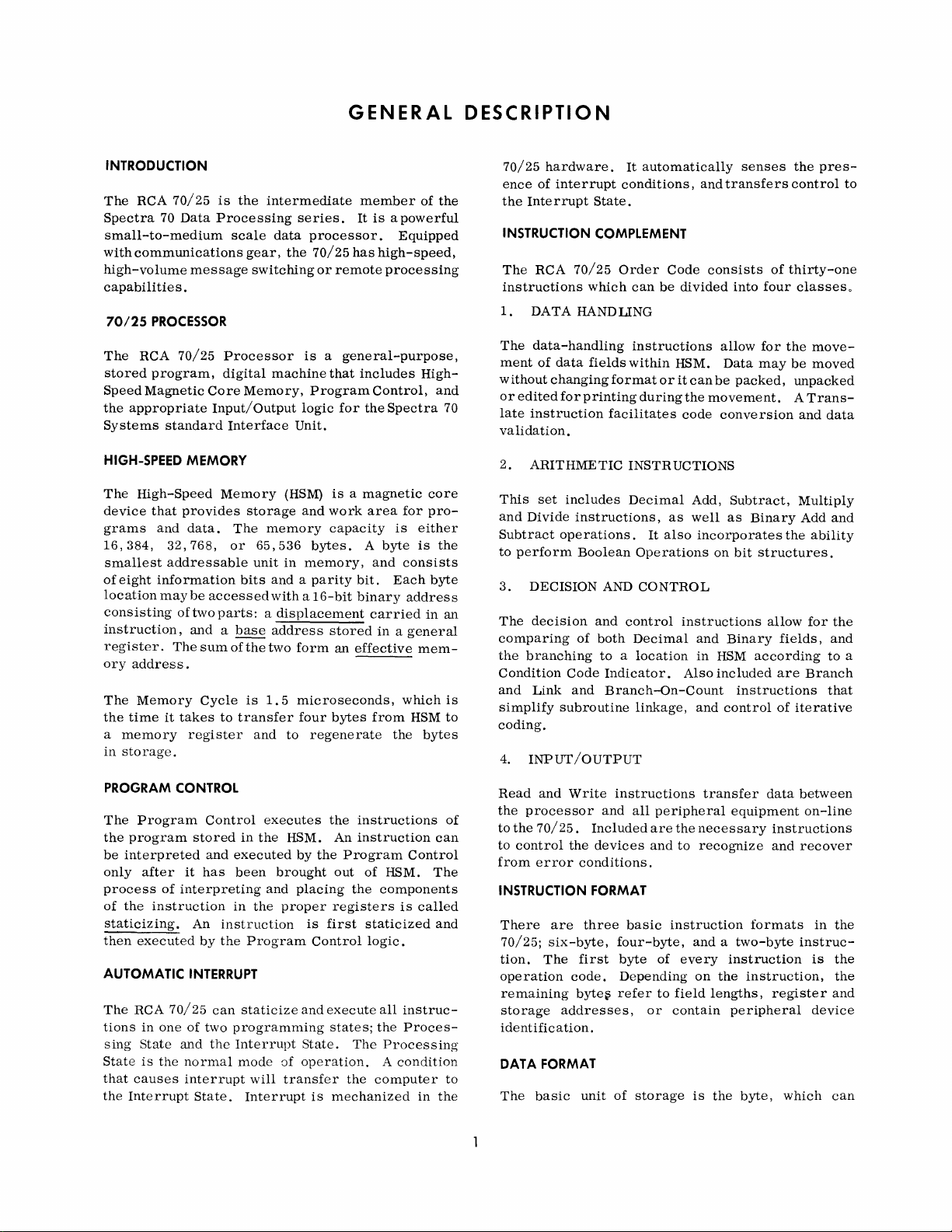
GENERAL
DESCRIPTION
INTRODUCTION
The
RCA
70/25
Spectra
70
Data
small-to-medium
with
communications
high-volume
capabilitie
70/25
The
RCA
stored
Speed
the
appropriate
Systems
HIGH-SPEED
The
High-Speed
device
grams
16,384,
smallest
of
eight
location
consisting
instruction,
register.
0ry
address.
The
Memory
the
time
a
memory
in
storage.
message
s.
PROCESSOR
70/25
program,
Magnetic
standard
MEMORY
that
provides
and
data.
32,768,
addressable
information
maybe
of
two
and a base
The
it
takes
register
is
the
intermediate
Processing
scale
gear,
data
the
series.
processor.
70/25
switching
Processor
digital
Core
Memory,
Input/Output
Interface
Memory
storage
The
or
65,536
unit
bits
accessed
is a general-purpose,
machine
Program
logic
Unit.
(HSM)
and
memory
bytes.
in
memory,
and a parity
with a 16-bit
parts: a displacement
address
sum
of
the
two
form
Cycle
is
1.
5
microseconds,
to
transfer
and
four
to
regenerate
member
It
is a powerful
has
high-speed,
or
remote
that
includes
Control,
for
the
is a magnetic
work
area
capacity
A
and
bit.
binary
carried
stored
an
effective
bytes
in a general
from
of
Equipped
processing
High-
Spectra
core
for
pro-
is
either
byte
is
consists
Each
byte
address
in
mem-
which
HSM
the
bytes
the
and
70
the
an
is
to
70/25
hardware.
ence
of
interrupt
the
Interrupt
INSTRUCTION COMPLEMENT
The
RCA
70/25
instructions
1.
DATA
HANDLING
The
data-handling
ment
of
data
without
or
late
changing
edited
for
instruction
conditions,
State.
Order
which
fields
format
printing
facilitates
It
automatically
Code
can
be
instructions
within
or
during
validation.
2.
ARITHMETIC
This
set
and
Divide
Subtract
to
perform
3.
DECISION
The
decision
comparing
the
branching
Condition
and
Link
simplify
includes
instructions,
operations.
Boolean
of
Code
and
subroutine
INSTRUCTIONS
Decimal
as
It
also
Operations
AND
CONTROL
and
control
both
Decimal
to a location
Indicator.
Branch-Qn-Count
linkage,
coding.
4.
INPUT/OUTPUT
senses
and
transfers
consists
divided
HSM.
it
the
code
into
four
allow
for
Data
may
can
be
packed,
movement. A Trans-
conversion
Add,
Subtract,
well
as
Binary
incorporates
on
bit
structures.
instructions
and
in
HSM
Also
included
allow
Binary
according
instructions
and
control
the
control
of
thirty-one
classeso
the
be
unpacked
and
Multiply
Add
the
fields,
are
Branch
of
iterative
pres-
movemoved
data
and
ability
for
the
and
to
that
to
a
PROGRAM CONTROL
The
Program
the
program
be
interpreted
only
after
process
of
the
instruction
staticizing.
then
executed
AUTOMATIC
The
RCA
tions
in
sing
State
State
is
that
causes
the
Interrupt
stored
it
of
interpreting
An
by
INTERRUPT
70/25
one
of
and
the
normal
interrupt
State.
Control
and
has
instruction
the
can
two
the
executes
in
the
HSM.
executed
been
in
and
the
by
brought
placing
proper
Program
staticize
and
programming
Interrupt
mode
will
State.
of
operation. A condition
transfer
Interrupt
the
An
the
Program
out
registers
is
first
Control
execute
states;
is
mechanized
instructions
instruction
of
HSM.
the
components
staticized
logic.
all
the
The
Processing;
the
computer
Control
is
called
instruc-
Proces-
in
of
can
The
and
to
the
Read
and
Write
the
processor
to
the
70/25.
to
control
from
INSTRUCTION FORMAT
There
70/25;
tion.
the
error
are
six-byte,
The
operation
remaining
storage
addresses,
instructions
and
Included
devices
conditions.
three
four-byte,
first
byte
code.
Depending
byte~
refer
all
basic
identification.
DATA
FORMAT
The
basic
unit
of
storage
peripheral
are
the
and
to
instruction
of
every
to
field
or
contain
transfer
data
equipment
necessary
recognize
instructions
and
formats
and a two-byte
instruction
on
the
instruction,
lengths,
register
peripheral
is
the
byte,
between
on-line
recover
instruc-
which
in
the
is
the
the
and
device
can
Page 8

represent,
or
numeric
packed
Extended
(EBCDIC) .
INPUT
The
devices
format.
/OUTPUT
RCA
through
in
the
unpacked
character,
Data
is
Binary-Coded-Decimal
70/25
communicates
eight
I/O
format,
or
two
represented
channels.
numeric
Interchange
with
one
digits
in
HSM
peripheral
alphabetic
in
the
in
the
Code
Each
peripheral
electronics
the
status
generated
Each
channel
ing
execution
processor.
in
the
system
powerful
in
of
the
by
an
is a separate
overlap
An
II
overlap
device
order
to
device,
I/O
command.
0
termination
to
facilitate
capabilities.
contains
transmit
and any
simultaneous
with
other
interrupt
efficient
its
own
to
the
error
mode,
channels
use
control
processor
conditions
allow-
and
is
included
of
these
the
2
Page 9
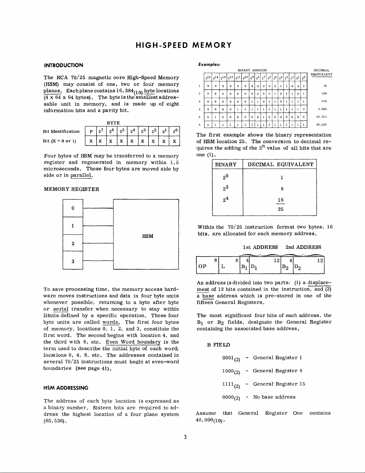
HIGH-SPEED
MEMORY
INTRODUCTION
The
RCA
70/25
(HSM)
planes.
(4 x 64 x 64
sable
information
Bit
Bit
Four
register
may
Each
unit
Identification
(X
= 0
or
1)
bytes
of
and
consist
plane
bytes).
in
bits
microseconds.
side
or
in
parallel.
MEMORY
REGISTER
0
1
2
magnetic
of
contains
The
memory,
and a parity
27
P
X
X X X X X
HSM
may
regenerated
These
core
one,
byte
and
BYTE
6 25
2
be
transferred
four
High-Speed
two
or
16,384(10)
is
the
smallest
is
made
bit.
24
in
memory
bytes
are
Memory
four
memory
byte
locations
addres-
up
of
3
22
2
21
X X X
to a memory
within
moved
side
HSM
eight
0
2
1.5
by
Examples:
215
0 0
0
0
0 0
0
1
The
first
of
HSM
quires
one
(1).
Within
bits,
BINARY ADDRESS
13
212
214
0
0
1
1
211
2
0 0 0 0 0 0 0
0
0 0 0
0
0
0
0
1
0
0
0 0 0
1 1
1
example
location
the
25.
adding
BINARY
0
2
3
2
24
the
70/25
are
allocated
10
9
8
2
2
0
1
1 0
0
1 1 1 1
0 0
0
1 1
1
27
2
shows
The
of
the
2n value
DECIMAL
instruction
for
each
1
st
ADDRESS
6
5
24
2
2
1 1
0 0
1
1 0 1
0
0 1
1 1
1 1 1 1
1
0 0 0 0
1
1
1 1
the
binary
conversion
of
EQUIVALENT
1
8
16
-
25
format
memory
3
0
22 21
2
2
1
0
0
1
0
1
1
1 1
1
1
I 0
0
o I 0
1 1
1
1
representation
to
decimal
all
bits
two
address.
2nd
ADDRESS
DECIMAL
EQUIVALENT
109
879
4.094
16.512
65,535
that
bytes,
25
reare
16
To
save
processing
ware
moves
whenever
or
serial
limits
defined
byte
units
of
memory,
first
word.
the
third
term
used
locations
several
70/25
boundaries
HSM
ADDRESSING
The
address
a
binary
dress
the
(65,536).
3
instructions
possible,
transfer
by a specific
are
locations
The
with
to
describe
0,
4,
instructions
(see
of
number.
highest
called
second
8,
etc.
8,
etc.
page
each
time,
returning
when
words.
0,
begins
Even
the
The
41).
byte
Sixteen
location
the
memory
and
data
to a byte
necessary
operation.
The
1,
2,
and
with
Word
initial
addresses
must
location
bits
are
of a four
in
first
3,
boundary
byte
begin
is
required
access
four
byte
after
to
stay
These
four
constitute
location
of
each
contained
at
even-word
expressed
plane
hard-
units
byte
within
four
bytes
the
4,
and
is
the
word;
as
to
ad-
system
in
An
address
ment
of
12
a
base
address
fifteen
The
Bl
most
or
General
B2
containing
B
FIELD
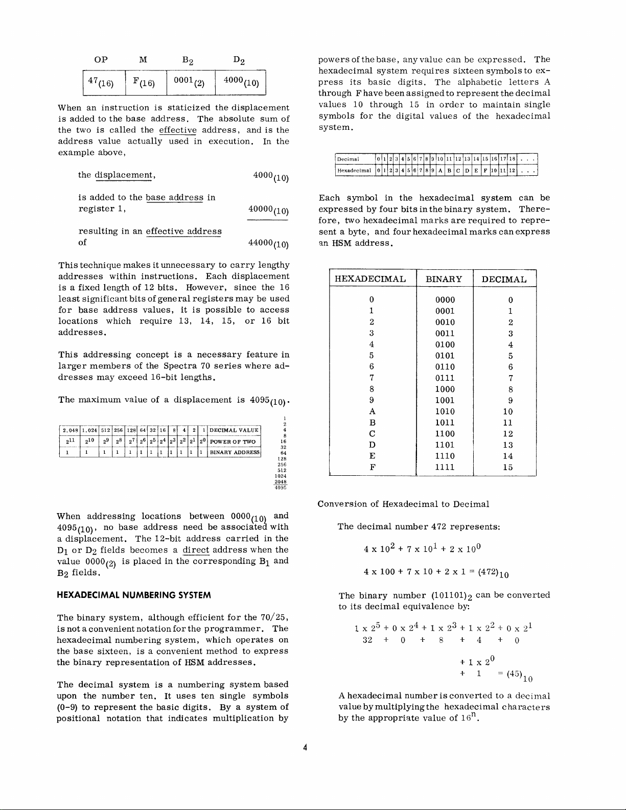
Assume
40,000(10)
is
divided
bits
contained
which
Registers.
significant
fields,
the
associated
0001
(2)
1000(2) -
1111(2) -
0000(2) -
that
General
.
into
is
four
designate
-
General
General
General-
No
base
two
parts:
in
the
pre-stored
bits
of
the
base
address.
Register
Register
Register
address
Register
(1) a displace-
instruction,
in
one
each
address,
General
1
8
15
One
and
(2)
of
the
the
Register
contains
3
Page 10
147
When
an
is
added
the
two
address
example
the
is
added
register
resulting
of
This
technique
addresses
is a fixed
least
significant
for
base
locations
addresses.
This
addressing
larger
dresses
The
r-,--
r----
maximum
2,048
211
1
members
1.024
10
2
1 1 1 1
OP M
the
base
called
to
1,
in
makes
within
length
address
which
exceed
value
256
128
9
8
2
2
F(16)
the
actually
the
an
instructions.
of
bits
values,
require
concept
of
.
64 32
27
26 2
1 1 1 1 1
(16)
instruction
to
is
value
above,
displacement,
may
512
0001(2)
is
staticized
address.
effective
base
effective
it
unnecessary
used
address
address
The
address,
in
Each
12
bits.
However,
of
general
registers
it
is
13,
possible
14, 15,
is a necessary
the
Spectra
16-bit
70
lengths.
of a displacement
--
16
4 2
1
8
3
5
22 21
24
2
2°
1
1
4000(10)
the
displacement
absolute
execution.
in
to
carry
displacement
since
may
series
is
DECIMAL
VALUE
POWER
OF
BINARY
ADDRESS
sum
and
is
In
4000(10)
40000(10)
44000(10)
lengthy
the
be
used
to
access
or
16
feature
where
4095(10)'
-~
TWO
the
the
16
bit
ad-
128
256
512
1024
2048
4095
of
in
16
32
64
powers
hexadecimal
press
through F have
values
symbols
of
its
10
the
base,
basic
through
for
system
digits.
been
the
digital
any
value
requires
assigned
15
in
can
The
to
order
values
be
expressed.
sixteen
alphabetic
represent
to
of
the
symbols
letters
the
maintain
hexadecimal
The
to
ex-
decimal
single
A
system.
Each
symbol
expressed
fore,
two
sent a byte,
an
HSM
HEXADECIMAL
2
4
8
in
by
four
hexadecimal
and
address.
0
1
2
3
4
5
6
7
8
9
A
B
C
D
E
F
the
bits
four
hexadecimal
hexadecimal
in
the
binary
marks
are
BINARY
0000
0001
0010
0011
0100
0101
0110
0111
1000
1001
1010
1011
1100
1101
1110
1111
system
system.
required
marks
DECIMAL
I
I
I
can
10
11
12
13
14
15
can
There-
to
repre-
express
0
1
2
3
4
5
6
7
8
9
be
When
addressing
4095(10)'
a
displacement.
D1
or
value
B2
fields.
no
D2
fields
0000(2)
base
HEXADECIMAL
The
binary
is
not a convenient
hexadecimal
the
base
the
binary
The
upon
(0-9)
positional
sixteen,
decimal
the
number
to
represent
system,
numbering
representation
system
notation
locations
address
The
need
12-bit
becomes a direct
is
placed
NUMBERING
in
the
SYSTEM
although
notation
for
system,
is a convenient
of
is a numbering
ten.
It
uses
the
basic
digits.
that
indicates
between
be
associated
address
carried
address
corresponding
efficient
the
for
programmer.
which
method
HSM
addresses.
ten
single
By a system
multiplication
0000(10)
when
the
operates
to
express
system
symbols
and
with
in
the
the
B1
and
70/25,
The
based
on
of
by
Conversion
4
of
The
The
to
decimal
4 x
binary
its
decimal
1 x 2
Hexadecimal
number
100
+ 7 x
number
equivalence
5
+ 0 x 24 + 1 x 2
to
Decimal
472
represents:
10
+ 2 x 1 = (472)10
(101101)2
by:
3
+ 1 x 22 + 0 x
32 + 0 + 8 + 4 + 0
+ 1 x 2
+ 1 = (45)10
A
hexadecimal
value
by
by
the
appropriate
multiplying
number
the
value
is
converted
hexadecimal
of
1 Gn .
can
be
0
to a decimal
converted
21
characters
Page 11
Examples:
1.
Convert
1 x
4096
2.
Convert
3 x
3 x 256
The
first
(I024h6
actual
Each
hexadecimal
four
bits.
binary
its
binary
3
16
2
16
768
example
which
machine
Therefore,
by
replacing
value.
(1024)16
+ 0 x
+
(3AFj16
+
10 x 16
+
10 x 16
+
has a decimal
to
Decimal
16
2
+ 2 x
16
1
+ 4 x
16
o + 32 + 4 = (4132)10
to
Decimal
1
+
15 x 16
+ 15 x 1
160
+
shows
(binary)
0001000000100100
address
character
hexadecimal
each
hexadecimal
0
15
the
hexadecimal
value
can
= (943)10
of
(4132)10.
is:
be
represented
is
character
0
address
converted
The
by
to
with
2.
3.
4.
5.
6.
An
effective
of
a
Base
address
___
specify
pute
an
The
decimal
exceed
Convert
binary:
a.
A4E8(16)
b.
E82C(16)
c.
3D71(16)
Convert
decimal:
a.
B5F9(16)
b.
F93D(16)
and!
which
effective
___
following
following
HSM
and a ___
values
or
base
address
address.
value
_
address
are
of a displacement
hexadecimal
hexadecimal
_
stored
fields
is
will
the
of
be
absolute
in
an
used
numbers
numbers
sum
.
The
instruction
to
com-
may
not
to
to
(0001000000100100)2 = 4096
The
second
dress
Exercise:
1.
A
a
the
3AF
has a decimal
byte
___
70/25
example
consists
bit,
and
HSM.
shows
is
of
the
that
value
__
___
+ 32 + 4 (4132)10
the
hexadecimal
of
943.
information
addressable
bits
unit
ad-
and
in
7.
8.
Convert
decimal:
a.
b.
c.
Convert
decimal:
a.
b.
following
1100011000001010(2)
0000101001001110(2)
0010110001100000(2)
following
55067(10)
7007(10)
binary
decimal
numbers
numbers
to
to
hexa-
hexa-
5
Page 12
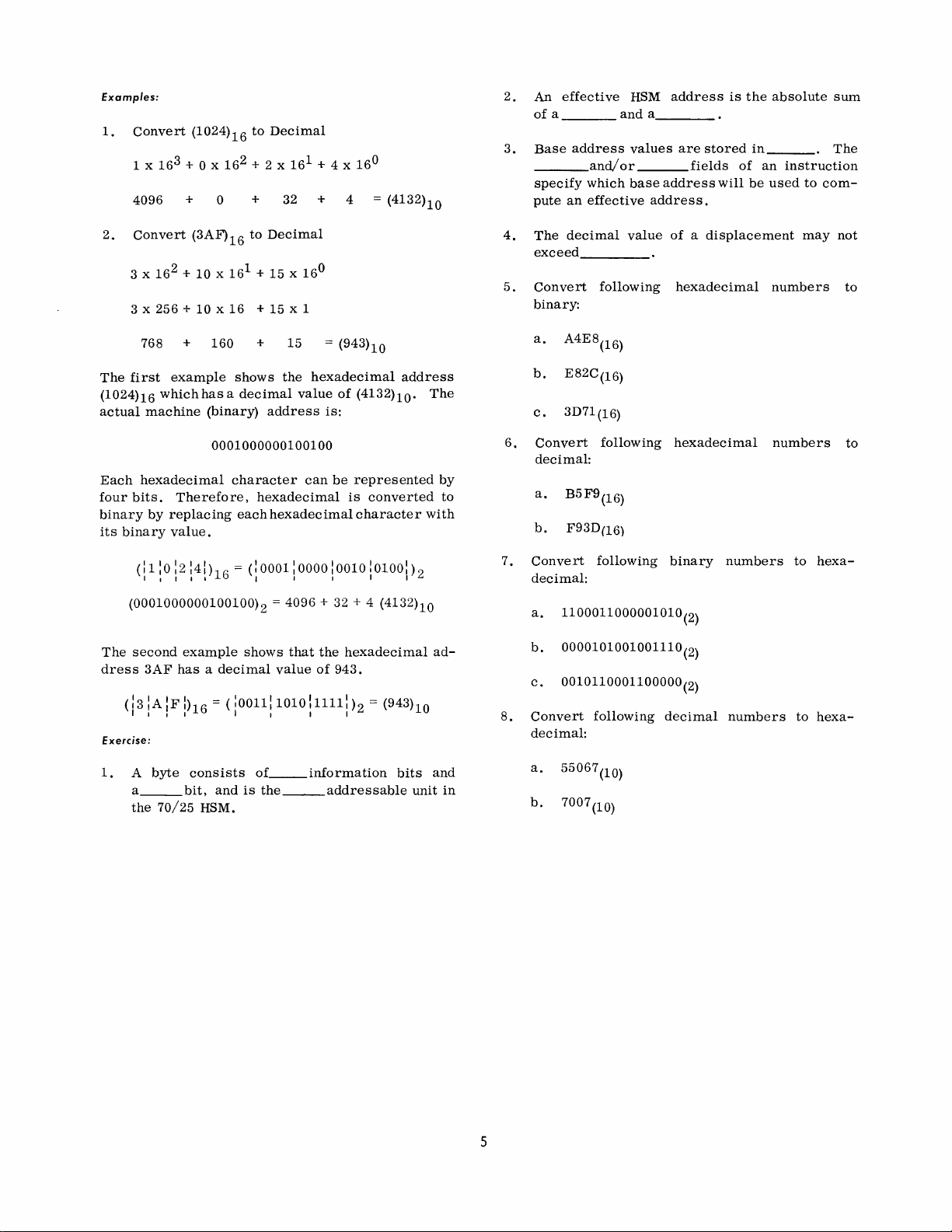
DATA
AND
INSTRUCTION
FORMAT
DATA
FORMATS
When
representing
character
(packed
UNPACKED FORMAT
A
byte
represent
format,
any
play
Some
the
hexadecimal
indicated
Char.
(unpacked
format).
in
the
one
for
characters
output
A
B
C
D
E
F
G
H C8
I
of
the
in
Hex.
Cl
C2
C3
C4
C5
C6
C7
C9 R
Char.
BLANK
.
(Period)
such
unpacked
alphabetic
example
that
as
more
representation
the
tables
ALPHABETIC
Char.
J
K
L
M
N
0
P
Q
SPECIAL
<
(
+
& 50
$
*
)
data, a byte
format),
format
or
numeric
is
required
are
to
appear
the
Printer
commonly
below.
Hex.
Char.
Dl
D2
S E2
D3
T
D4
U
D5
V
D6
W
D7
X E7 7 F7
y
D8
D9
Z E9 9 F9
CHARACTERS
Hex.
EO
4B
4C
4D
4E
5B
5C =
5D
may
store a single
or
two
numeric
uses
all
eight
character.
for
the
storage
on
any
type
or
Typewriter.
used
characters,
of
their
bytes
NUMERIC
Hex.
Char.
0
1
2
3
E3
E4 4
E5 5 F5
E6
6 F6
E8 8 F8
Char.
-
(Minus
/ Hyphen)
,
(Comma)
%
# 7B
@
t (Quote)
Space
Hex.
60
61
6B
6C
7C
7D
7E
40
digits
bits
of
are
Hex.
FO
Fl
F2
F3
F4
to
This
of
dis-
and
as
PACKED
In
digits
sign
The
packed
a
UNPACKED
PACKED
It
either
has
SIGN RECOGNITION
In
is
If
one
negative.
Mter a decimal
result
Thus,
data
L
(11 punch)
a
EDITED FORMAT
DATA
packed
except
in
the
following
and
byte
shown
should
be
packing
its
zone
decimal
recognized
(1)
All
(2)
Qriftherightmostbitisa(0}z
(1110)2'
the
sign
of
the
is
one
(1100)2
(1101)2
in
preparing
fields,
e.,
for a negative
zone
portion
FORMAT
data
for
four
example
packed
in
noted
and
arithmetic
as
one
has a low-order
remaining
of
for
for
the
in
the
format,
the
low-order
hexadecimal
or
numeric
positive
bits
arithmetic
the
positive
negative
user
least
of
one
rightmost
shows
format.
1
FO 1 F3
16
103
I
(as
in
the
unpacking a field
portions
operations
ifthe
(1111)2
bits
following:
source
may
follow
field
an
significant
(11012),
byte
stores
byte
bits.
the
Each
location
format.
1 F1 I
1 21 1
example
sign
bit
of
is
(0)
2'
operation
card
existing
overpunch
two
which
contains
same
field
represents
F6
1 F2 1 F1 I 80 I
OS
I
above)
the
rightmo
reversed.
the
sign
position
Le.,
(1)
2'
and
it
is
considered
the
sign
input
for
procedures,
of
the
position
generates
decimal
the
in
un-
that
when
st
byte
of a field
contains:
(1010)2'
at
least
of
the
numeric
minus
A
decimal
assumed
of
the
right
portion,
all
ones
However,
before
arithmetic
numeric
to
contain a sign
most
will
have
(11112),
the
decimal
it
may
be
operation.
byte.
the
used
field
in
All
four
numeric
as
in
unpacked
the
high-order
other
bytes,
high-order
field
an
operand
format
four
in
the
bits a value
must
be
packed
in a decimal
is
bits
zone
of
6
A
packed
format
A
field
sary
I -
numeric
with a single
in
edited
edit
symbols.
1
1 -
field
EDIT
form
is
01 01
0
may
instruction
unpacked
23
I
+
1
2
1
be
and
placed
(see
contains
48
3
in
page
neces-
4
edited
33).
1
-I
Page 13
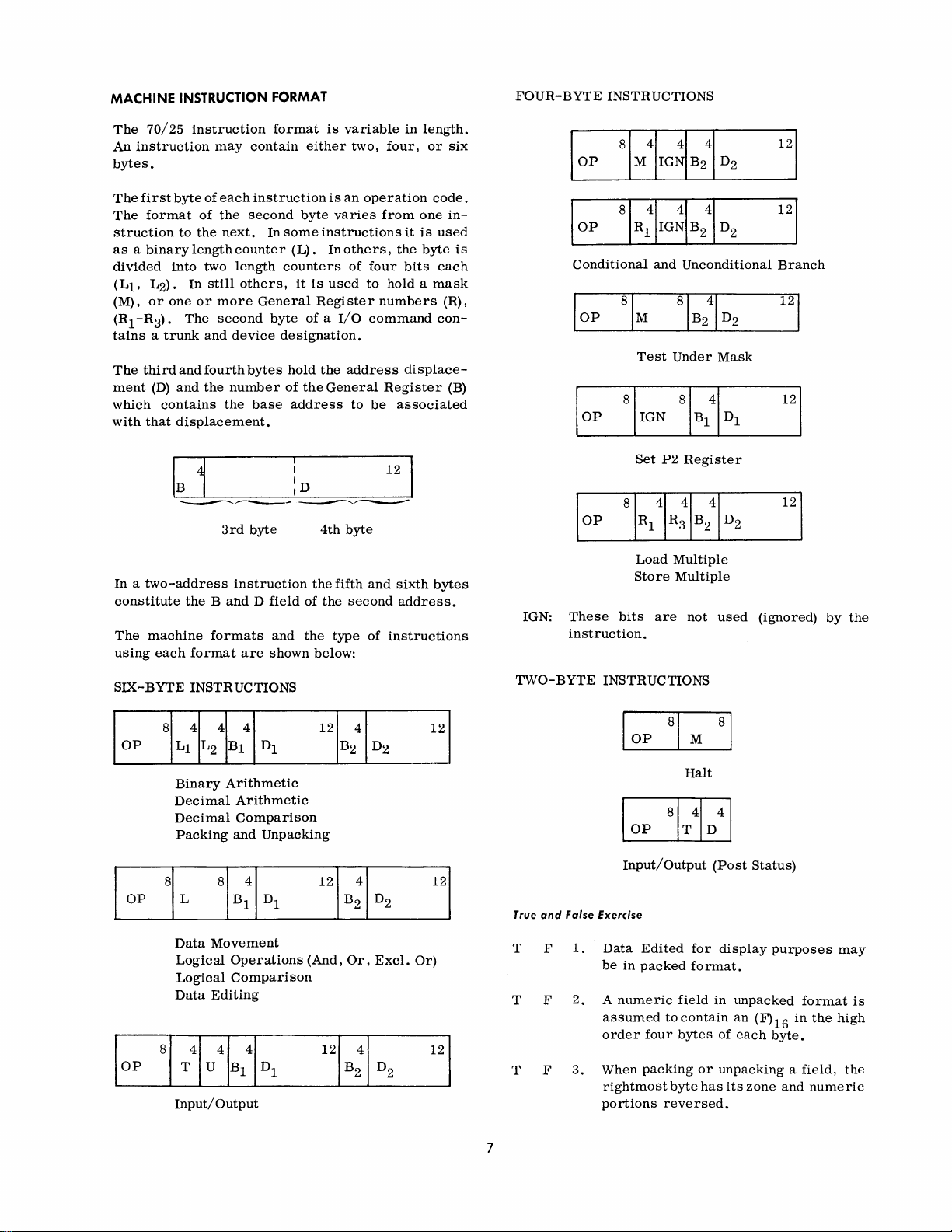
MACHINE
The
An
bytes.
The
The
struction
as a binary
divided
(Ll'
(M),
(R
1
tains a trunk
The
ment
which
with
INSTRUCTION FORMAT
70/25
instruction
first
byte
format
to
into
L2).
or
one
-R3).
third
and
(D)
and
contains
that
displacement.
instruction
may
of
each
of
the
the
next.
length
counter
two
length
In
still
or
more
The
second
and
device
fourth
the
number
the
3rd
format
contain
instruction
second
In
some
counters
others,
General
byte
designation.
bytes
of
base
byte
either
byte
instructions
(L).
it
is
Register
of a I/O
hold
the
the
address
4th
is
variable
two,
is
an
operation
varies
In
others , the
of
four
used
to
command
address
General
to
be
byte
in
length.
four,
or
code.
from
one
it
is
used
byte
bits
each
hold a mask
numbers
con-
displace-
Register
associated
six
in-
is
(R),
(B)
FOUR-BYTE
lop
1
op
Conditional
INSTRUCTIONS
81M41IG~IB241D2
81
R:IIG~I
Test
Set
B241
and
Unconditional
Under
P2
Register
D2
Mask
121
121
Branch
In a two-address
constitute
The
using
SIX-BYTE
the
machine
each
format
INSTRUCTIONS
Binary
Decimal
Decimal
Packing
Data
Logical
Logical
Data
Band D field
formats
Movement
instruction
are
Arithmetic
Arithmetic
Comparison
and
Operations
Comparison
Editing
the
of
and
the
shown
below:
Unpacking
(And,
the
fifth
second
type
Or,
and
sixth
address.
of
instructions
Excl.
Or)
bytes
IGN:
TWO-
True
T F
T F
These
instruction.
BYTE
and
False
1.
2. A numeric
Load
Multiple
Store
Multiple
bits
are
not
INSTRUCTIONS
Halt
Input/Output
Exercise
Data
Edited
be
in
packed
assumed
order
four
field
to
contain
bytes
format.
for
used
(Post
display
in
unpacked
an
of
each
(ignored)
Status)
purposes
(F)16
byte.
format
in
the
by
the
may
is
high
Input/
Output
7
T F
3.
When
packing
rightmost
portions
or
byte
has
reversed.
unpacking a field,
its
zone
and
numeric
the
Page 14

T F
T F
4.
5.
The
negati
The
tion
a
general
values
ve
Bl
or
format
(1101)2
signs.
B2
fields
contain
register.
and
of
the
(1001)2
machine
HSM
are
valid
instruc-
address
of
T F
T
Each
a
12
An
either
instruction
displacement
bit
address.
two,
three,
6.
7.
F
field
is
variable
four,
accommodates
in
length;
or
six
bytes.
8
Page 15
INTRODUCTION
An
interrupt
the
detection
for
an
of
sensing
matic
mechanized
software
unnecessary
develops,
demands.
response
PROGRAMMING
All
instructions
(1)
the
State
of
operation.
transfer
State
the
original
facility
immediate
for
transfer
in
with
and
This
independently
Processing
(P2).
The
from
where
it
Processing
of
to
eliminate s program
provides
exceptional
program
exceptional
of
control
the
RCA
the
hardware
halt
the
system
STATES
are
executed
State
Processing
An
interrupt
the
Processing
remains
conditions,
conditions
70/25
computer
allows
of
his
(P1) ,
until
State.
an
automatic
response.
to
software
hardware.
interrupt
sensing
the
user
production
in
one
or
State
is
causes
State
instructed
means
and a method
The
function
and
the
has
Combining
makes
when
an
of
external
to
program
processing.
of
two
(2)
the
Interrupt
the
normal
the
computer
to
the
Interrupt
to
return
INTERRUPT
The
an
for
auto-
been
it
error
a
states:
mode
to
to
counter
instruction
tions
puter
(see
resets
returns
interruptable.
"PENDING"
State.
Interrupt
instruction.
to
the
lows
automatic
interrupt
process.
TYPES
system
instruction
is
may
remains
page
the
Control
occurs
the
Process
address
the
point
OF
INTERRUPT
is
now
in
the
is
staticized
updated
to
be
39)
P2
be
executed.
executed
in
this
is
executed.
counter
to
Any
until
the
to
contain
state
Pl.
interrupt
computer
only
Therefore,
after
interrupt,
of
the
instruction
where
linkage
permits
considerations
Interrupt
the
the
All
in
the
P2
until a STPP2
The
to
its
The
Interrupt
after
the
when
that
interrupt
the
when
State.
contents
address
thirty-one
state,
STPP2
original
attempted
returns
to
termination
the
system
the
P1
immediately
took
user
programming
Each
of
of
instruc-
and
the
instruction
instruction
value,
State
will
the
Process
counter
place.
to
disregard
time
the
the
next
com-
and
is
not
of
returns
holds
fol-
This
his
P2
be
an
PROCESSING
During
the
address
stored
and
forty-one
121512141213121212111210129128127126125124123122121120
Each
time
the
contents
the
address
instructions
computer
the
in
the
BYTE
an
remains
STATE
execution
of
the
P1
counter
(29)16'
(40)10
instruction
of
the
P1
of
the
may
be
of
next
PI
counter
next
executed
in
this
instructions
instruction
(reserved
COUNTER
is
staticized
is
instruction.
in
state
in
to
be
HSM
BYTE
(41)10
in
updated
All
the
P1
until
the
executed
forty
the
P1
to
thirty-one
state.
an
interrupt
occurs.
INTERRUPT
When
interrupt
to
the
counter
five
STATE
an
exceptional
initiated,
instruction
(reserved
(2D)16)'
BYTE
(44)10
condition
the
whose
HSM
P2
hardware
address
forty-four
COUNTER
is
detected,
transfers
is
(2C)16
stored
in
and
P1
state
(28)16
state
contain
The
and
control
the
P2
forty-
is
an
I
There
are
Processing
1.
I/O
Device
2.
Operation
3.
Arithmetic
4.
Elapsed
1/0
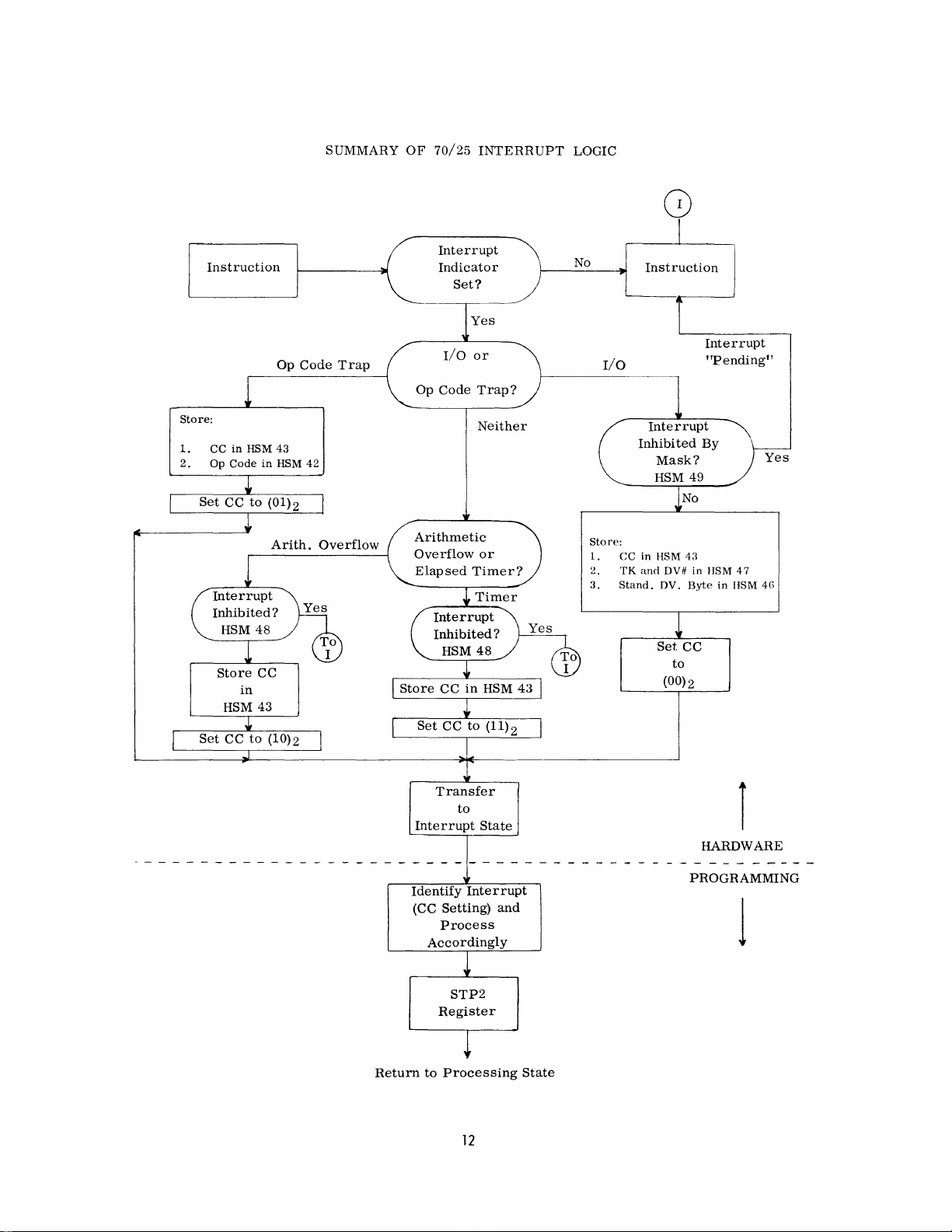
INTERRUPT
An
interrupt
Input/Output
indicates
1.
The
I/O
fully
Indicator
(see
page
2.
The
channel
tion
is
command
event,
set
to
The
purpose
notify
system
able.
With
four
State:
(Manual
Code
Overflow
Timer
occurs
Command.
one
of
two
instruction
(ERROR).
bit
53).
and
now
free,
(NORMAL
the
26
(1)2'
(see
of
software
this
conditions
Trap
Overflow
after
possible
was
In
in
the
Standard
device
and
bit
of
the
page
normal
that
knowledge,
that
can
or
Termination)
or
Divide
the
A
Exception
termination
termination
terminating
not
completed
this
case,
the
Device
that
executed
ready
to
receive
TERMINATION).
Standard
Device
53).
termination
an
the
I/O
interrupt
channel
software
interrupt
of
interrupt
conditions:
success-
Secondary
Byte
the
instruc-
the
Byte
is
can
each
is
(1) 2
next
In
this
is
avail-
the
is
to
use
9
Page 16

efficiently
taining
A
communications
control
generates
ruption
the
Standard
Prior
the
eight
by
the
an
is
distinguished
to
entering
matically:
1.
Stores
The
present
in
the
20 - 21
forty-three
overlap
I/O
operator
I/O
Device
the
state
Channels.
device
Interrupt.
Byte
the
ofthe
value
ofthe
bits
(2Bh6'
capabilities
request,
at
the
console
Console
by
the
fact
is
set
P2
state,
Condition
Condition
of
the
reserved
of a system
or a request
typewriter
that
to
(1)2'
the
computer
Code
Code
request
the
Indicator,
is
HSM
con-
for
also
inter-
27
bit
auto-
stored
location
of
OPERATION CODE
If
an
instruction
code
is
not
one
of
interrupt
Operation
Prior
is
Code
to
entering
initiated.
matically:
1.
2.
Stores
in
Stores
interrupt
two
the
20 - 21
(2A)16'
the
the
state
illegal
in
TRAP
is
staticized
the
Trap.
the
bits
the
thirty-one
This
P2
state,
of
the
Condition
oflocation
operation
reserved
in
which
legitimate
interrupt
the
forty-three
code
HSM
the
Operation
codes,
is
called
computer
Code
Indicator
that
caused
location
auto-
(2Bh
forty-
an
an
6'
the
The
2.
Stores
Number)
reserved
Device
the
3.
Stores
rupting
forty-six
See
page
Byte.
The
P2
struction
occurs.
a
Branch
(00) 2
indicates
I/O
device.
stored
routine
For
example,
one
on
been
depressed,
contain:
~~
Condition
Trunk
127
~~
Number
53
counter
of a routine
This
On
in a reserved
to
identify
Trunk
the
identification
of
HSM
Number
Number
BYTE
126
125124123\
Trunk
the
Standard
device
(2Eh6'
for a desc
contains
routine
Condition
that
The
Trunk
the
if
the
three,
then
Code
Indicator
the
interrupting
location
is
stored
is
(47)10
in
the
ription
to
tests
interrupt
and
area
device
Console
and
HSM
is
(Trunk
forty-seven
in
the
stored
in
22\ 21
Device
Number
Device
Byte
reserved
of
the
the
address
be
executed
the
Condition
instruction).
had
been
Device
of
HSM,
that
caused
Typewriter
the
Interrupt
location
then
set
and
device
(2Fh6'
20 - 23 bits,
the
24 -27
120
for
the
HSM
Standard
of
the
when
interrupt
Code
A
setting
caused
Number
have
allowing
the
interrupt.
is
button
forty-seven
to
(00)
Device
in
The
and
bits.
Inter-
location
Device
first
(with
by
been
Device
had
would
2'
the
in-
of
an
the
BYTE
The
two
dicate
3.
high-order
the
length
00
01
or
11
Sets
the
routine
(01)2
indicates
an
illegal
viously
the
situation,
be
an
error,
latter
case,
struction
For
example,
for
Convert
on
the
could
10
Condition
tests
staticized
that
70/25.
be
bits
of
the
two-byte
four-byte
six-byte
the
that
operation
the
illegal
or
an
the
interrupt
is
not
the
Decimal
However,
simulated
state.
ARITHMETIC OVERFLOW
A
carry
out
of
the
high-order
operand
(FAh6
causes
(FD) 16
rupt
during
or a Subtract
interrupt.
operation
occ
urs
.
the
If
are
the
(42)10
of
the
instruction.
Code
to
Condition
the
interrupt
code
in
the
PI
operation
intentional
part
of
70/45
would
by
instructions
AND
DIVIDE EXCEPTION
execution
Decimal
operands
not
properly
Operation
instruction
instruction
instruction
(01)2'
The
Code. A setting
was
in
the
instruction
state.
Depending
could
interrupt.
could
simulate
the
70/25
order
operation
cause
the
decimal
code
an
position
of
an
Add
(FBh6
of a Divide
edited,
Code
in-
interrupt
caused
by
pre-
on
actually
In
the
an
in-
code.
(4E)16
interrupt
conversion
in
the
P2
of
the
first
Decimal
instruction
Decimal
an
inter-
of
Trunk
3
Device
1
the
ferring
10
Hardware
20 - 21
(2Bh6'
and
to
stores
bits
resets
the
the
of
the
Interrupt
state
reserved
code
State.
of
to
the
Condition
location
(10)2'
forty-three
before
Code
trans-
in
Page 17

ELAPSED
TIMER
INTERRUPT
Exercise:
General
clock.
power)
added
register
intervals
value
Before
of
reserved
reset
INHIBITING
All
be
(31)16
selected
the
tion.
eight
and
A
and
channels
If
channel
addressed
Three
forty-eight
Timer,
CHANNEL
A
mask
plex
arithmetic
INTERRUPT PRIORITIES
the
to
pre-stored
transfer
the
Condition
to
interrupts
inhibited.
allows
eight
The
I/O
a (0)2
mask
seven
an
interrupt
bit
interrupt,
Register
Every
power
the
contents
overflows,
between
location
(11)2'
INTERRUPT
the
I/O
channels.
rightmost
bit
positions,
channels,
bit
inhibits
of
10010110
to
interrupt,
zero,
remains
to
that
positions
(30)
Arithmetic
interrupts.
of
101
in
overflow
Op
Code
16-2/3
except
three,
on
16
I/O
Elapsed
Overflow
Divide
Zero
serves
milliseconds
supply
generates a (1) 2 bit
of
Register
interrupt
interrupts
in
the
register
to
the
P2
state,
Code
is
stored
forty-three
the
Operation
Reserved
user
to
HSM
inhibit
The
bit
positions
(20-27),
0-7.
A (1)2
it.
LOCATION
allows
and
five,
an
I/O
channel
busy
until a Post
channel,
is
(22_2°)
allow
the
user
Overflow,
the
22_20 allows
but
inhibits
or
divide
Trap -immediate
Timer
and
Exception
as
takes
is
controlled
(see
the
in
the
(2Bh6'
location
interrupt
user
places a mask
of
the
correspond
bit
permits
49 (31)16
channels
inhibits
and
six.
Status
executed
in
reserved
to
inhibit
and
21=Overflow
22=Timer
0co
2
Timer
interrupt
exception.
1
2
3
an
elapsed
(using
Zero.
place.
page
current
20 - 21bits
and
Code
Trap
forty-nine
reserved
one,
two,
interrupt
is
inhibited,
instruction,
(see
page
the
MULTIPLEX
Multiplex
and
caused
time
60
cycle
that
When
the
The
time
by
the
13).
setting
the
code
may
on
all
into
loca-
to
the
interrupt
four
from
the
53).
location
Elapsed
Channel
Multi-
by
is
of
or
T F
T F
T F
T F
T F
T F
T F
T F
T F
T F
T F
T F
T F
1.
2.
3.
4.
5.
6.
7.
8.
9.
10.
11.
12.
13.
14.
15.
16.
17.
Only
fifteen
structions
Interrupt
The
main
Processing
The
Processing
ruptible.
The
Interrupt
The
Condition
changing
The
Condition
prior
to
The
two
in
the
reserved
The
Processing
counter
next
instruction.
The
PI
interrupt.
The
computer
until
another
The
operation
Operation
The
Standard
an
Operation
Interrupt
only
interrupt
Describe
Describe
Trap.
Write
the
possible
be
stored?
Describe
memory
interrupt
of
the
can
State.
program
State.
State
Code
states.
Code
going
into
program
to
indicate
counter
remains
interrupt
Code
Device
Code
from
that
the
use
two
uses
masks
interrupts.
what
when
each
takes
place.
thirty-one
be
executed
is
State
is
not
is
is
always
the
P2
counters
area
of
State
the
is
destroyed
occurs.
code
is
Trap.
Byte
Trap.
any
r/o
can
be
of
HSM
of
the
necessary
Where
is
stored
of
the
70/25
in
executed
is
not
interruptable.
stored
prior
set
state.
are
stored
memory.
uses
only
address
of
by
in
the
P2
stored
is
stored
device
inhibited.
location
Operation
to
inhibit
must
in
reserved
four
types
inthe
in
the
inter-
to
one
the
the
state
on
is
the
49.
Code
all
they
to
00
an
on
of
11
Page 18
SUMMARY
OF
70/25
INTERRUPT
LOGIC
Instruction
Store:
1.
CC
2.
Op
in
Code
Store
in
HSM
HSM
in
CC
43
Op
43
HSM
Arith.
Code
42
Overflow
Trap
Interrupt
Indicator
Set?
Yes
I/O
Op
Code
Arithmetic
Overflow
Elapsed
or
Trap?
Neither
or
Timer?
No
I/O
Store:
1.
2.
3.
Instruction
Interrupt
Inhibi
CC
in
TK
and
Stand.
ted
Mask?
HSM 49
No
HSM
43
DV#
in HSM
DV.
Byte
Set
CC
to
(00)2
Interrupt
"Pending!!
By
47
in
HSM
Yes
48
Return
Transfer
to
Interrupt
Identify
(CC
Setting)
Process
Accordingly
STP2
Register
to
Processing
State
Interrupt
and
12
r
HARDWARE
PROGRAMMING
1
State
Page 19
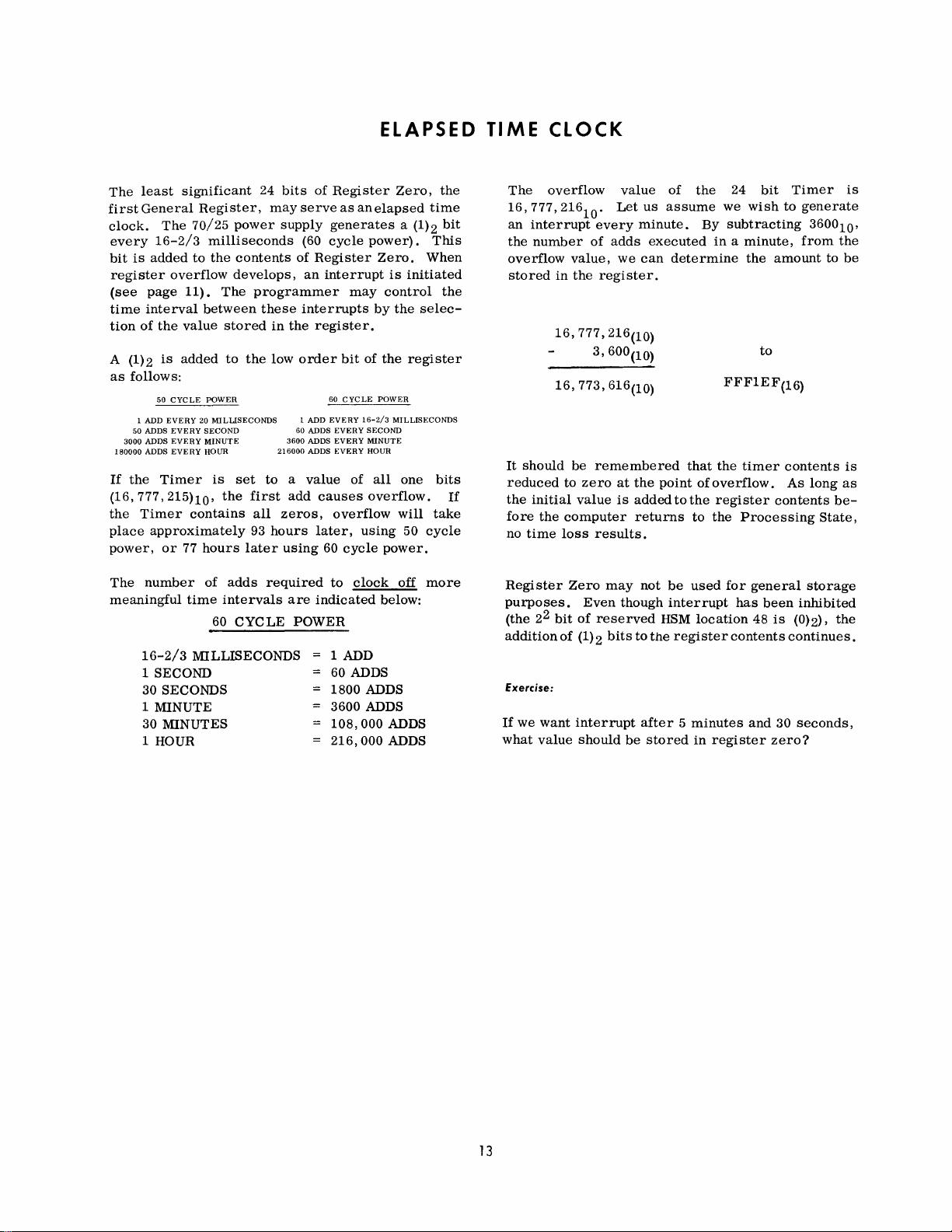
The
least
significant
first
General
clock.
every
bit
register
(see
time
tion
A (1) 2
as
If
is
of
follows:
1 ADD
50 ADDS
3000
180000
the
The
16-2/3
added
overflow
page
interval
the
value
is
added
50
CYCLE
EVERY
EVERY
ADDS
EVERY
ADDS
EVERY
Timer
70/25
to
11).
(16,777,215>10'
the
Timer
place
power,
The
meaningful
16-2/3
1
1
contains
approximately
or
77
number
time
MILLISECONDS
SECOND
30
SECONDS
MINUTE
30
MINUTES
1 HOUR
Register,
power
milliseconds
the
contents
develops,
The
programmer
between
stored
to
the
POWER
20
MILLISECONDS
SECOND
MINUTE
HOUR
is
set
the
first
all
93
hours
later
of
adds
intervals
60
CYC
24
bits
of
may
serve
supply
(60
of
Register
an
these
interrupts
in
the
register.
low
order
1 ADD
60 ADDS
3600
ADDS
216000
ADDS
to a value
add
causes
zeros,
hours
later,
using
required
are
indicated
LE
POWER
Register
as
an
generates
cycle
interrupt
may
bit
of
60
CYCLE
EVERY
16-2/3
EVERY
SECOND
EVERY
MINUTE
EVERY
HOUR
of
overflow
using
60
cycle
to
clock
1 ADD
60 ADDS
1800
ADDS
3600
ADDS
108,000
216,000
ELAPSED
Zero,
the
elapsed
power).
Zero.
by
the
POWER
all
overflow.
power.
below:
a (1)2
When
is
initiated
control
the
selec-
register
MILLISECONDS
one
will
50
cycle
off
more
ADDS
ADDS
time
bit
This
the
bits
take
If
TIME
The
CLOCK
overflow
16,777,21610.
an
interrupt
the
number
overflow
stored
It
should
reduced
the
initial
fore
the
no
time
Regi
ster
purposes.
(the
22
addition
Exercise:
If
we
want
what
value
value
Let
every
of
adds
value,
we
in
the
register.
16,777,216(10)
3,600(10)
16,773,616(10)
be
remembered
to
zero
at
the
value
is
added
computer
loss
Zero
Even
bit
of
of
(1) 2
returns
results.
may
though
reserved
bits
to
interrupt
should
be
of
the
us
assume
minute.
executed
can
determine
point
to
not
be
we
By
in a minute,
that
the
of
overflow.
the
register
to
the
used
interrupt
HSM
location
the
register
after 5 minutes
stored
in
register
24
bit
wish
to
subtracting
the
amount
to
FFF1EF(16)
timer
contents
As
contents
Processing
for
general
has
been
48
is
contents
and
continues.
30
zero?
Timer
generate
360010'
from
to
long
State,
storage
inhibited
(0)2),
seconds,
is
the
be
is
as
be-
the
13
Page 20

INTRODUCTION
ASSEMBLY
TO
THE
RCA
LANGUAGE
70/25
FORMAT
The
ming
REQUIREMENTS
RCA
70/25
system
machine-oriented
program
system.
statements
Program
forms
1.
2.
3.
for
The
written
Form.
one
of
Generates
Allocates
Notifies
subsequent
source
the
the
function.
OPERATION
Every
output
OPERATION
the
NAME
The
it
is
location
NAME
alphabetic
tion
that
only
asterisk
is
to
OPERAND
statement,
listing
above
FIELD
NAME
desired
of
entry
of
alphabetic
do
not
exception
may
be
used
FIELD
FIELD
comment,
field
three
field
to
the
(A-Z)
exceed a total
appear
for
Assembly
designed
program
language
on
Each
following
an
object
data
areas
assembler
except a line
(Cols.
functions.
(Cols.
symbolically
field
generated
symbol
character
and/or
to
the
symbol
in
an
output
is
an
automatic
to
translate
into a machine-coded
execution
on
consists
the
RCA
Spectra
single-line
functions:
program
or
instruction.
constants.
to
perform a specific
used
must
have
10-14)
1-6
only)
specifying
may
identify
by
the
must
consist
followed
numeric
Col.
listing
of
1
six
entry
if
by
(0-9)
characters.
above
the
comment.
program-
a
symbolic
the
RCA
of
one-line
70
Assembly
statement
solely
an
entry
be
used
the
leftmost
statement.
of
at
least
any
combina-
characters
is
statement
70/25
per-
for
in
one
when
that
an
the
of
The
one
The
an
line
IDENTIFICATION
The
contents
functions.
positions,
assigned
positions,
is
used
counter.
zeros.
number
77-80
ADDRESSING
A
symbolic
of
addressing
symbol
location,
sired
the
struction
As
stated
bination
There
six
characters,
as
Each
either
or
from
has
it
in
the
address
on
of
are
columns
to
columns,
the
If
previously,
the
two
phabetic.
The
following
symbols:
VALID
Al
STKNKI
C
INI
FIELD
of
the
In
the
START
73-76,
the
object
initial
not
numeric,
object
derived
zeros.
name
is
and
referencing a location.
been
used
may
be
OPERAND
of
the
left
the
'NAMEd'
alphabetics
restrictions:
(2)
are
IDENTIFICATION
statement,
may
contain a name
program.
77-80,
setting
are
ofthe
the
instruction
from
the
most
in
the
referenced
field.
end
line
the
symbol
(A-Z)
the
first
examples
If
numeric,
Assembly
counter
the
value
frequently
NAME
as
frequently
The
value
of
the
of
assembly
may
or
(1) no
name
character
of
valid
has a sequence
field
the
first
the
last
the
starts
in
used
field
to
assigned
data
field
be
any
numerics
may
must
and
has
two
four
to
four
contents
sequence
at
all
columns
means
When
define
as
de-
or
in-
coding.
com-
(0-9).
exceed
be
al-
invalid
be
a
a
is
The
OPERAND
OPERATION
specifies
that a constant
OPERAND
If
an
instruction
OPERAND
for
that
particular
COMMENTS
A
comment
lowing
from
blank
may
in
Column
the
the
required
column.
be
used
FIELD
field
field.
field
Thus,
entry
Operation
field
must
instruction.
may
appear
OPERAND
OPERAND
The
entire
for a comment
1.
has
is
follow
entry.
entries
if
the
is
being
the
value
Code
the
in
any
It
entry
statement
if
an
as
required
OPERATION
defined,
of
the
constant.
appears,
prescribed
statement
must
line
by
be
separated
at
least
(to
line
Col.
asterisk
by
the
field
the
the
format
fol-
one
71)
appears
INVALID
The
symbolics
HSM
LOCATION
tained
and
begin
14
OPN
BEGINERR
IA
IN.I
Assembler
that
address
COUNTER, a program
by
the
Assembler,
makes
at
HSM
assignments.
location
(Space
(Too
(First
(Period
builds a table
appear
is
in
assigned
2000.
invalid
many
character
characters)
invalid
character)
not
character)
containing
the
name
field. A specific
to
each
symbolic.
counter
generates
these
Assume a routine
alphabetic)
all
The
main-
addresses
is
the
to
Page 21

The
Controlling
NAME
places
the
counter.
instructions,
always
able.
placed
the
contains
If
in
current
a
Consider
ASSEMBLY
STATEMENT
*Note
that
the
to
orient
the
instruction
**NO
SYMBOL
IMPLICIT
BASE
Code,
OPERATION
START
initial
As
value
memory
the
counter
the
statement
the
table,
value
in
the
following
CONTENTS
OF
LINE
A
5-byte
field
A
2-byte
field
A
lO-byte
Constant
A
6-byte
Instruction
A
4-byte
Instruction
Location
Counter
to
an
(TAG)
ASSIGNED.
ADDRESS
OPERAND
Xt7D~t
of
(2000ho
is
allocated
is
incremented
address
at
the
contains a name,
and
assigned
the
counter.
examples:
SYMBOL
(TAG)
~
Work
ADDR
WCON 2007
STRT
is
advanced
address.
one
even
SYSTEM
next
an
ADDRESS
ASSIGNED
2000
2005
2018
byte
location
in
the
for
location
that
address
COUNTER
by
the
Location
fields
so
that
availname
equal
FOR
TillS
LINE
ADVANCE
LOCATION
2000
2005
2007
2018
2024
Assembler
and
TO:
*
**
it
is
to
If
the
displacement
flagged.
If
we
move
OP
I L I
I I
I I
D2(16)
~I
I I
Additional
1.
If
more
placement
contents
used.
2.
If
two
placement
3.
If
no
object
The
3850 8173
0100 4195
3750 3978
ABLE
to
00(16) I
rules
9(16) 3750(10) A(16) I 3978(10)
for
than
one
(notover4095(10»,
produce
or
more
the
highest
register
produces a valid
instruction
statement
exceeds
BAKER
implicit
register
the
registers
4095,
the
I I I
aadress
produces a valid
smallest
produce
numbered
contains
is
flagged.
anOP
the
statement
object
result
generation:
the
register
displacement
the
same
register
displacement
code
and
is:
whose
is
used.
zeros.
is
dis-
is
dis-
the
The
User
may
his
Assembly
bler
to
assign
ments.
Address
implied
NAME
We
for
This
System.
whenever
OPERATION
MVC
MVC
tell
the
implicit
Statements.
NAME
OPERATION
START
USING
USING
USING
With
this
information,
address
putes
the
that
B1-D1
tion.
Assume
the
assigned
symbol
base
The
table.
value
difference
explicitly
Statements,
base
latter
Assembly
assignment,
gives
(or
two
the
addresses
from
the
is
addresses
method
Base
they
OPERAND
Dl
(L.
Bl).
SI
(L).
S2
OPERAND
X'064'
*.9
4195.10
*+8190.11
the
the
B2-D2)
names
The
assembly
effective
the
displacement.
state
base
or
he
may
and
is
called
values
are
D2 (B2)
what
not
explicitly
base
are
Explicit
Implied
through a series
Set
Location
Using
100(10)
USing
4195(10)
USing
8290(10)
Assembly
least
displacement,
field
in
the
ABLE
and
3850(10)
subtracts a smaller
(Symbol
register
ask
the
compute
the
implicit
considered
Base
Base
addresses
Counter
to
in
General
in
Genera)
in
General
selects
object
BAKER
and
8173(10)
Table)
values
Assem-
displace-
stated.
Addresses
Addresses
to
of
Using
100(10)
Register
Register
Register
the
base-
and
instruc-
have
in
Address.
Base
to
use,
9
10
11
com-
been
the
in
be
4.
The
Code.
tions
ulate
5.
Address
for
an
option)
block
added
ment
RELATIVE
As
mentioned
field
has
The
aSSignment
byte
of
The
programmer
right
or
or
minus
As
an
assigned
UsingStatementis
The
User
and
constants
register
base
address
•
will
to
values
address
constant
If
other
not
address
contents.
to
be
values.
ADDRESSING
above, a symbol
an
address
assigned
will
the
defined
field.
may
left
of
this
(-)
value.
example,
as
assume a field
follows:
30
[
1-1_°°
an
must
write
to
physically
be
stored
purposes
controlling
means
are
relocatable.
constants,
appearing
by
be
the
address
reference
address
by
WARE
__
°1
__
Assembly
Controlling
additional
load
and
in
general
should
be
defined
code
used,
the
Float
factors
not
to
the
in
the
the
Location
of
the
any
location
indicating a plus
(WARE)
02_0_3-1
instruc-
manip-
registers
with
(DC, A
program
are
displace-
NAME
Counter.
leftmost
to
the
(+)
has
been
15
Page 22

The
programmer
to
the
SELF-
right-end
RELATIVE
may
refer
(3003)
of
WARE+3
ADDRESSING
this
(in
the
field
OPERAND
as:
field)
CHARACTER
A
character
quote
marks
Example:
may
be
preceded
specified
by a C.
by
enclosing
it
in
single
The
asterisk,
specifies
the
address.
byte
generated
asterisk,
position
by
the
statement
Assuming
given
statement
2006
and
terisked
SELF-
DEFINING
In
the
previous
as
the
current
The
with a plus
to
the
right
the
location
*-3
furnishes
address
the
first
value
address
by
the
or
or
left
line.
line,
is
relocatable.
VALUES
example, a self-defining
incremented a symbolic
Self-defining
hexadecimal,
dresses,
I/O
trunk
may
also
for
this
DECIMAL
A
one
to
Assembler
Example:
values
and
express
and
device
be
usedfor
purpose,
six
decimal
converts
may
character.
masks
numbers.
location
they
digit
it
character
of
statement
minus
of
counter
*+6
generates
an
address
address.
be
in
and
should
number
to
the
the
location
is
always
value,
the
first
value
of
three
They
lengths,
Self-defining
addresses.
not
exceed
may
binary
of
an
operand,
counter
the
line.
Thus,
can
address
byte
generated
is
2000
an
address
1997.
value
forms;
may
modify
and
decimal,
represent
When
4095(10).
be
used.
equivalent.
as
leftmost
the
for
An
as-
of
ad-
values
used
The
a
a
of
OPERAND
CtA',
Example:
The
same
three
value:
The
character A (or
1100
0001)
statements
is
below
in
desired.
generate
binary
the
OPERAND
CtA'
X'C1'
192,
CHARACTER
HEXADECIMAL
DECIMAL
All
will
generate
1100
0001
2
EXPRESSIONS
3
An
expression
or a combination
field
of
an
Assembly
contains
one
factor.
NAME
The
compound
simple
expressions.
is a symbol
of
the
or a self-defining
two,
statement. A simple
OPERATION
START
MVC
AP
expression
is
written
OPERAND
XtABC
ABLE
Xl
(6),120(4)
made
up
in
the
t
(3)
,BAKER
of
two
value,
operand
expression
or
three
OPER-
NAME
ATION
OPERAND
OPERAND
ABLE
(4) ,
OPERAND
0049,
HEXADECIMAL
Up
to
six
self-defining
quote
marks
to
represent
Examples:
OPERAND
X'3F',
Four
Forty-nine
hexadecimal
value
by
preceded
binary
configurations
Represents
uration
(4)
ABLE
4910
digits
enclosing
by
an
used
to
to
(Interrupt
may
the
X.
This
the
0011
1111.
define
address
Mask)
be
written
digits
option
such
as
binary
length
location
as
in
single
is
used
masks.
config-
of
* e
55(3),
MVC
AP
Expressions
classifications,
lute
expression
that
is
fixed,
The
address
is
relative
ment
a
located
Assembly
preSSions
absolute
catable
SUMMARY
A
simple
defining
and
may
in
addresses
ones
OF
expression
value
to
memory.
rules
must
RULES
SUM1 e SUM2+66(6),
are
further
absolute
generates
and
may
generated
the
starting
be
altered
for
the
be
followed
may
are
required.
FOR
FORMING
is a single
used
as
BAKER*ABLE
divided
and
an
not
into
relocatable.
object
be
legitimately
by a relocatable
point
of
when
coding
formation
closely.
be
generated
EXPRESSIONS
symbol,
an
operand.
two
machine
the
program
blocks
of
compound
*+T
ANG e 5
additional
An
abso-
address
changed.
expression
are
Otherwise,
where
or
one
seg-
re-
ex-
relo-
self-
16
Page 23

A
compound
of
at
least
pressions.
with
addition
(*) •
*+50
expression
two,
but
not
The
expressions
(+),
subtraction
ABLEeSTARTP
is
an
more
arithmetic
than
three
may
be
(-),
or
combination
simple
ex-
compounded
multiplication
15*6+3
Illegal
1.
2.
3.
4.
5.
Expressions:
OO(}l-CAT
50*HOPE
DOG+CAT+HOPE
176
- DOG
OOG -
CAT -HOPE
Contains
two
Multiplication
No
subtraction
Single
relocatable
Two
subtraction
relocatable
of
relocatable
operator
symbol
operators
symbols
symbol
preceded
by
Compound
arithmetic
pound
ones
operator.
The
following
eROUT
An
expression
absolute
also
absolute
Rl,
R2 =
A =
absolute
Thus,
the
X'3X',
39*x'H4'+2
Relocatable
stated
below:
1.
An
expression
relocatable
2.
If
there
be
preceded
3.
If
three
and
only
operator.
expressions
operator.
must
be
are
becomes
symbols
if
it
relocatable
following
168,
expressions
symbols.
is
one
by a subtraction
relocatable
one
must
Simple
separated
incorrect:
ABLE
BAKER
absolute
and/or
has
symbol
are
one
all
self-defining
or
RI-R2E.603,
must
must
contain
relocatable
symbols
may
be
preceded
not
begin
expressions
with
if
of
the
following
symbols
self-defining
absolute
5*5+1,
conform
either
symbol,
(-)
are
or
end
with
within
com-
one
and
only
one
SIZE++
it
PRICE
contains
values.
only
It
forms:
value
expressions:
RI-R2+37,
to
the
rules
one
or
three
it
must
not
operator.
present,
one
by a subtraction
an
is
IMPLIED
The
any
NAME
LENGTHS
length
of
reference
OPERATION
an
operand
to
length
MVC
MVC
In
line
two
of
the
bytes
moved
to
the
defined.
NAME
from
number
If
BAKER
OPERATION
location
allocated
is
BAKER DS
storage
An
in
field
If
implied
an
instruction
is
a
name
area,
set
is
the
length
to
zeros.
defined
implied
that
is
in a statement
or a self-defined-value,
When a
NAME
compound
expression
OPERATION
MVC
may
be
in
an
Assembly
OPERAND
ABLE
ABLE,
example
BAKER
when
the
name
OPERAND
CL3
length
exceeds
flagged,
the
implied
is
OPERAND
ABLE,
A+B-C
implied
(3)
,BAKER
BAKER
above,
to
the
name
of
a 3
is
three.
the
and
using
used
statement.
the
ABLE
byte
value
the
object
length
as
Implied
is
by
omitting
Explicit
Length
Implied
Length
number
is
BAKER
permitted
length
an
asterisk
is
one.
all
operand,
Length
Length
of
equal
was
of
A
4.
Relocatable
with
the
expressions
plication.
The
following
expressions:
DOG,
DOG+CA T e
symbols
multiplication
are
legitimate
are
examples
DOGel03,
FIGHT,
may
not
operator.
operands
of
correct
*910.
ABLE+437*6
be
compounded
Only
in
relocatable
absolute
multi-
the
implied
most
ASSEMBLER
The
DS
working
The
number
lowed
full
word),
17
length
factor
CONTROLLING
(Define
storage
by
the
appears
in
the
Storage)
of
units
letters
is
the
expression.
code
and
input/output
of
memory
C,
H,
in
the
length
assigned
CODES
allocates
to
or F (byte,
OPERAND
areas.
be
to
the
and
reserves
reserved,
halfword,
field.
left-
fol-
or
Page 24

A
symbol
the
address
The
Location
with
the
counter
The
operand
mented
if
a
symbol,
fined
in
be
allocated
may
be
mats.
NAME
READIN
The
character
tells
the
byte
fields
location
The
statements
NAME
1.
READIN
2.
READIN
appearing
of
the
Counter
ORG
code.
to
the
value
may
be a symbol
or
decremented)
then
the
NAME
beginning
re-allocated
OPERATION
DS
"C",
Assembler
beginning
counter.
OPERATION
DS
DS
in
leftmost
maybe
This
appearing
it
must
field.
to
following
to
at
the
NAME
byte
set
ofthe
code
in
or
to
the
an
field
reserved
any
sets
asterisk
or a self-defining
have
been
With
this
tool,
at
any
desired
accommodate
OPERAND
80C
the
area
allocate
the
80
current
consecutive
OPERAND
20F
40
H
is
assigned
desired
the
location
operand
previously
areas
location,
varying
length
position
area.
value
field
(incre-
value;
de-
may
for-
80,
one-
of
or
the
Example
.
Areas
NAME
allocated
NAME
PACN
PCOD
PDAT
PAMT
PTYP
RACN
RCOD
RDAT
RAMT
(ORG
and
DS
Codes)
OPERATION
ORG
DS lOC
DS 2C
DS
DS
DS
ORG
DS
DS
DS
DS
ORG
allocated
field
but
may
are
by
the
be
not
left
referenced
Cont'cJ
OPERAND
INAR
4C
7C
2C
lOC
INARl
2C
4C
7C
INAR+80
DS
code
blank
I
I
1
are
for
directly.
Reset
not
areas
Payment
Transaction
Receipt
Transaction
Location
Counter
value
after
INAR
above
cleared.
that
must
to
The
be
CONSTANTS
The
DC
(Define
ory
for,
value
is
pressed
adecimal
constant
CHARACTER
in
is
Constant)
and
stores
written
one
of
or
address
implied
CONSTANTS
in
the
three
by
code
the
value
OPERAND
forms,
constant.
the
value
both
allocates
of a constant.
field,
and
as a character,
The
length
in
the
operand
mem-
is
of
field.
The
ex-
hex-
each
allocate
first
vance
and
as
counter
locates
Example
example
the
then
the
second
the
location
allocate
to
the
40
fields
(ORG
same
(20F)
example
next
and
Assume a read-in
contains
maximum
name
transactions
size
the
area,
format.
NAME
INAR
OPERATION
DS
ORG
NACN
NCOD
NDAT
DS
DS
DS
NCUS DS
NADR DS
NTYP
DS 2C
NAMT DS
amount
counter
20
fields
of
two
DS
Codes)
area
record
and
of
instructs
(40H)
even
byte
bytes
is
in
three
is
80
to
name
memory.
the
to
the
next
of
four
bytes
advances
address,
each.
allocated
different
characters.
every
OPERAND
80C
INAR \
)
lOC
2C (
4C
I
25C
30C
)
7C
However,
Assembler
word
boundary.
each;
the
and
for a file
formats.
We
field
within
New
Transaction
the
to
ad-
wherelocation
then
al-
that
The
want
each
Account
to
A
constant
ten
on
one
verted
marks,
to a byte.
is
NAME
EOF
CaDS
HEXADECIMAL
A
hexadecimal
character
cannot
value
digits
decimal
pressed
be
is
written
not
value)
digits
exceeding
OPERATION
DC
An
explanation
EDITING
(page
not
exceeding
statement
The
preceded
OPERATION
DC
16
line.
value,
by a C.
characters
Each
enclosed
OPERAND
C'END
DC CtOI2AB'
CONSTANTS
constant
constant
expressed
in
(starting
is
used
must
when
one
or
by a character
an
even
number
thirty-two.
from
the
to
generate a byte.
be
Each
OPERAND
X'4020206B20204B202060'
of
the
above
example
33).
may
character
in
single
OF
RUN'
used
more
of
value.
of
hexadecimal
pair
left
end
is
given
in
the
of
be
is
lieu
of
the
in
writ-
con-
quote
of
a
bytes
The
hexa-
ex-
DATA
18
Page 25

ADDRESS
An
There
(EXPRESSION)
address
must
constant
parenthesis
ing
example
1.
2.
3.
CONSTANT
may
be
stored
be a separate
of
this
type.
and
The
preceded
s.
OPERATION
DC A(*-6)
DC
DC A(256)
as a two-byte
statement
constant
by
an A as
OPERAND
ACSTRT)
line
is
enclosed
in
the
constant.
for
each
in
follow-
DEFINING
The
clude
The
EXPLICIT
define
specific
explicit
correspond
CONSTANT
constant
references
gCLn'cv'
gXLn'cv'
ALn'cv'
L
n =
n
length
to
the
format
may
not
number
may
not
takes
physical
LENGTHS
may
to
length.
exceed
of
bytes
exceed
precedence
length
be
expanded
256
(16)10
of
the
10
if
it
'cv'
to
does
value.
in-
not
Explanation
1.
stores
- 6
as a constant
2.
Stores
LOCATABLE).
3.
Stores
stant
DEFINING
Constants
defined
In
of
the
in
the
format
constants
constant
the
current
the
value
the
binary
(NOT
RELOCATABLE).
REPETITIVE
in
repetitive
CONSTANTS
character
fashion.
gC'cv'
gX'cv'
above, g represents
to
be
generated,
value.
value
of
the
Location
(RELOCATABLE).
of
STRT
as a constant
equivalent
and
hexadecimal
and
the
of
actual
'cv'
256
Counter
as a con-
form
may
number
represents
(RE-
be
NAME
In
acter
length
constant
to a length
If
the
an
third
of
explicit
OPERATION
DC
DC
DC
example
the
constant
of
two
was
defined
of
fi
ve
length
OPERAND
2C
2XL5
2CL2tlAB'
above,
lAB,
specified.
on
the
.
is
L3
t ABC t
'3F6'
second
not
00000003F600000003F6
the
B,
rightmost
was
truncated
In
like
line
was
included
when
ExpressionConstant, a lengthof 4 bytes
and
the
generated
constant
is
aligned
on
boundary.
When a length
constant
value
of
ber
of
bytes,
is
the
not
other
than
aligned
expression
the
high-order
and
exceeds
four
is
not
(4)
is
relocatable.
the
bits
of
truncated.
Absolute
are
Example:
NAME
expressions
generated
OPERATION
in
2's
may
have
complement
OPERAND
negative
form.
Binary
GENERATED
ABCABC
lAlA
char-
because
manner,
padded-out
defining
is
assumed,
an
even
specified,
If
assigned
the
values
num-
value
which
Generated
Constant
a
the
an
word
the
the
are
The
statements,
NAME
CONI
CON2
generate
ABCABCABC
The g factor
address
The
example,
constant
implied
is
OPERATION
DC
DC
may
not
statement.
length
of
three
and
and
be
properly
CONI
two.
OPERAND
3C'ABC'
2X'3F4'
03F403F4.
incorporated
and
CON2,
in
the
in
an
above
CONI
CON2
PROGRAM
The
munication
assembled
fies
The
gram.
ENTRY
A
point
ENTRY
bol
field
19
two
codes,
the
location(s)
EXTRN
CODE
separate
in
the
appears
must
is
not
DC
DC
LINKING
CODES
ENTRY
between
independently.
addressed
code
defines a symbol
ENTRY
program
in
the
be
used
in
used
on
All
(-2)
ALI
(-5)
and
two
programs
The
verb
must
(see
START
OPERATION
the
OPERAND
this
line.
EXTRN,
ENTRY
by
another
appear
code
field.
11111110
11111011
provide
that
code
in
another
for
for
field
com-
have
been
speci-
program.
pro-
each
entry
exception).
and a sym-
The
NAME
Page 26

EXTRN
CODE
RUN
AND
SEGMENT
CONTROLLING
CODES
Reference
ed
by
the
appear
gram.
a
NAME
for
EXTRN
symbol
field
EXAMPLE
One
use
program
SINE
subroutine
COS,
and
the
SINE-COSINE
SINE
or
computed.
RTN
after
SINE-COSINE
NAME
SINE
to a symbol
EXTRN
Code. A separate
every
symbol
appears
must
be
used
is
not
used
OF
ENTRY
of
the
ENTRY
to a subroutine.
has
one
EXTRN
routine
COS
depending
The
SINE-COSINE
computing
OPERATION
START
ENTRY
EXTRN
in
another
appearing
in
the
in
the
on
this
AND
EXTRN
and
EXTRN
Assume
two
ENTRY
point;
RTN.
can
on
the
function.
ROUTINE
OPERAND
COS
RTN
program
statement
in
another
OPERATION
OPERAND
line.
codes
that a SINE-COpoints;
Programs
BRANCH
which
function
routine
BRANCHES
is
field
field.
is
to
SINE
to
is
defin-
must
pro-
and
The
link
and
using
either
to
be
to
The
first
and
last
statements
must
be a START
If
a
program
ed
individually,
must
begin
START
In
a
gram, a START
an
CODE
addition
initial
value
and
END
contains
the
sections
second
with a CSECT
to
flagging
code
can
and
identify
statement,
control
the
set
of
which
and
start
the
an
the
source
respectively.
are
succeeding
code.
of
the
source
location
entry
into
program
to
be
sections
counter
the
load-
pro-
to
pro-
gram.
START
self-defining
sets
NAME
program
NAME
BEGIN
must
the
location
field
(see
OPERATION
START
appear
value,
in
written
the
counter. A symbol
is
considered
ENTRY
code).
OPERAND
S'064'
OPERATION
in
the
OPERAND
appearing
an
ENTRY
Set
counter
Establish
as
point
Location
to
an
entry
field.
field,
in
the
into
the
100(10)'
"BEGIN"
point.
A
COS
NAME
BGN
RTN
The
that
RTN.
main
allows
B
B
END
MAIN
PROGRAM
OPERATION
START
ENTRY
EXTRN
B
END
program
the
defines
SINE-COSINE
RTN
RTN
OPERAND
RTN
COS
~COS
COS
point
COSINE
RTN
as
routine
is
in
an
to
ENTRY
an
ENTRY
the
SINE-
Routine
point
BRANCH
to
END
CODE
The
END
input
statements
AND
field
program.
isked
address
NAME
CSECT
The
CSECT
new
section
vious
section.
section,
second
field
may
bol
used
other
segment
code
informs
have
specifies
A
symbol,
may
the
appear
OPERATION
END
CODE
code
identifies
(segment)
The
START
therefore
and
CSECT
succeeding
contain a symbol
in
one
segment
in
the
the
Assembler
been
processed.
starting
self-defining
in
the
OPERAND
STARTP
both
and
the
termination
code
should
sections
or
be
can
program.
that
address
value,
OPERAND
STARTPisthe
name
gram
address
the
identifies
be
only.
left
blank. A sym-
be
referenced
all
source
The
OPER-
of
the
or
aster-
field.
of
the
starting
beginning
of
the
the
used
for
The
NAME
by
object
pro-
of
prefirst
the
any
a
20
Page 27

Example
of
CSECT
NAME
OPERATION
OPERAND
registers
references
page
3).
and
are
to
not
compute
included
displacements
in
an
expression.
when
base
(See
If
no
ORG
entry,
segment
be
loaded
following
previous
The
above
of
three
HSM
location
the
first
EQUATE
The
Equate
to
values,
bolics.
then
a
will
the
segment
example
segments.
11 001 O.
two
segments
CODE
(EQU)
or
The
statement,
BGN
SEG2
illustrates a program
The
second
The
third
at
the
command
assigns
the
same
START
CSECT
ORG
CSECT
ORG
END
segment
segment
location
assigns
address
1000
BGN+100
SEG2
consisting
is
will
named
symbolic
to
two
loaded
over
SEG2.
names
sym-
at
lay
The
first
operand
a
register.
ter.
NAME
The
first
operand
while
the
second
The
USING
Load
Multiple,
instruction
eral
register.
The
assumed
incorporating
in
the
source
The
OPERATION
USING
USING
code
does
Move
places
value
another
program.
denotes
second
may
is
simple
not
Character
the
actual
of a register
USING
the
value
assumed
operand
specifies
OPERAND
STARTP+6,5
*-10,6
be a relocatable
and
absolute.
load a general
or
Branch
base
address
may
statement
to
the
expression
register.
and
in a gen-
be
altered
at
any
be
regis-
Link
place
in
A
by
enters
the
assigns
another
The
above
the
name
address
appearing
viously
field
of a prior
BASE
REGISTER
The
USING
base
address
gisters
table
of
NAME
XYZ
name
the
value
in
similar
NAME
BTAG
statement
BT
AG
previously
in
the
defined.
CONTROLLING
Code
values
at
object
these
values,
OPERATION
EQU
XYZ
in
6.
One
fashion.
OPERATION
EQU
causes
in
the
assigned
Operand
It
must
statement.
indicates
will
time.
and
the
name
table,
field
have
be
The
then
OPERAND
symbol
the
Assembly
and
to
ATAG.
must
appeared
CODES
to
the
in
specific
Assembler
uses
6
table,
may
be
equated
OPERAND
ATAG
assign
The
have
been
in
Assembler
general
them
and
to
to
enter
to
it
symbol
pre-
the
name
what
creates
to
assign
the
re-
it,
to
The
base
It
is
table
only
value
not
prior
NAME
function
from
NAME
necessary
to
changing
OPERATION
USING
of
the
the
Assembly
OPERATION
DROP
to
drop a base
it
with a second
DROP
table.
OPERAND
*+500,5
code
is
to
OPERAND
6
address
USING
delete
from
state-
a
the
ment.
EXTENDED
The
fining
a
Condition
listed
MNEMONIC
assembler
the
various
instruction.
below
INSTRUCTIONS
provides a Simplified
options
replace
the
available
The
BC
and
pseudo
via
the
associated
method
the
Branch
operation
of
de-
codes
mask.
on
21
Page 28

PSEUDO
OP
B
NOP
BH
BL
BE
BO
BP
BM
BZ
Examples:
FUNCTION
Branch
No
Branch
Branch
Branch
Branch
Branch
Branch
Branch
Unconditional
Operation
on
on
on
on
(Arithmetic)
if
Ones
on
on
(Arithmetic)
if
Mixed
on
(Arithmetic)
if
Zero
OPERATION
B
BH
BZ
High
Low
Equal
Overflow
or
(after
Plus
-Minus
or
(after
Zero
or
(After
Branch
TM)
Branch
TM)
Branch
TM)
OPERAND
BEGIN
ERR
ZERO
BC
EQUIVALENT
BC
XIF',
Sl
Be
X'O',
Sl
BC
X'2',Sl
BC
X'4',
Sl
BC
X'8',Sl
BC
Xlll,Sl
BC
X'2',
Sl
BC
X'4',Sl
BC
X'8',Sl
5.
Indicate
true
T F
T F
T F
T F
T F
6.
Describe
7.
by
codes.
How
an
whether
0 r
false.
a.
b.
c.
d.
e.
many
EXTRN
A DS
memory
area
to
Three
fined
The
length
plicit.
If
the
a
single
the
rightmost
A
hexadecimal
an
odd
will
have a zero
left
end
flagged
the
use
external
statement?
the
code
and
blanks.
types
with
length
DC
number
and
in
of
symbols
follOWing
the
reserves
clears
of
constants
DC
instruction.
of a constant
of a constant
statement
byte
will
constant
of
hexadecimal
digit
the
statement
the
listing.
the
EXTRN
may
statements
a
portion
the
reserved
may
must
defined
is
17
be
truncated.
consisting
padded
will
and
ENTRY
be
identified
be
be
bytes
digits
at
are
of
de-
ex-
by
of
the
be
Exercise:
1.
What
of
the
bler
2.
What
3.
If a statement
and
of
the
a.
b.
c.
4.
Indicate
value.
Self-Defining
C'9'
X'4645'
CIA'
246
C'A9'
does
the
symbol * (asterisk),
Assembler
program?
is a redundant
has a symbol
an * (asterisk)
following
Name
the
Asterisk
one.
Asterisk
two.
the
Is
address
same.
address
address
type
Value
Coding
name?
as
its
true?
and
of
the
form,
is
is
following
in
first
asterisk
name
name
tell
operand,
in
column
the
Assem-
the
name
address
address
address
self-defining
field
which
are
plus
plus
8.
Explain
bler
program.
1
9.
Using
Assembler
to:
a.
b.
c.
d.
10.
Define
machine
a.
the
restrictions
on
the
placing
the
Assembler
and
Set
the
Location
ting
of
1000.
Provide
ABLE
which
Set
aside a working
bytes.
Provide
the
L
an
following
instructions.
of
machine
linkage
is
not a part
address
abbreviations
imposed
ENTRY
coding
instructions
Counter
to a subroutine
constant
by
statements
form,
to
of
storage
the
necessary
an
initial
this
area
of
3000.
as
used
Assem-
in
write
set-
called
program.
of
by
the
the
the
75
b.
c.
S
d.
e.
22
Page 29

(Cont'd)
10.
f.
S2
g.
M
h.
T
D
i.
11.
Briefly
compound
a.
b.
implied
implied
c.
relocatable
d.
12.
Write a statement
the
hexadecimal
stant
an
define
explicit
the
following
expression
length
base
address
expression
generating
constant
length
'XYZ'.
of
terms:
6.
six
repetitions
Give
the
con-
of
What
would
13.
Write a statement
bytes.
even
word
14.
How
are
defined?
15.
Using
equating
the
a)
name
the
b)
16.
Describe
statements.
with
base
the
statement
Align
boundary.
32
bit
the
EQU
address
ENDP.
name
the
addresses?
generate?
allocating a work
the
left-hand
relocatable
command,
of
the
NINE
to
purpose
How
are
of
general
end
expression
write
name
the
value
the
area
of
the
BEGIN
9.
USING
registers
of
100
area
on
an
constants
statements
to
the
and
DROP
loaded
23
Page 30

The
RCA
70/25
instructions
1.
DATA
The
movement
moved
unpacked,
ment. A translate
version
2.
ARITHMETIC
This
tiply,
Add
and
the
ability
structures.
3.
DECISION
The
the
comparing
and
the
a
Condition
and
Link
simplify
coding.
4.
INPUT/OUTPUT
This
cessor
70/25.
control
from
DATA
Data
another
can
occur
unpack,
MOVE
The
Move
or
one
field.
led
by
accesses a word
to
the L Register
less
than
(in
machine
is
transferred
that
HANDLING
data
handling
of
data
without
and
branching
error
changing
or
edited
and
data
set
includes
Divide
Subtract
to
perform
decision
Code
and
Branch
subroutine
set
reads
and
all
It
includes
the
devices,
conditions.
AND
MOVEMENT
may
be
moved
with
or
during a moving
or
to
unpack
CHARACTER INSTRUCTION
Character
word
at a time
The
number
the L Register.
the
number
format)
before
Order
Code
can
be
divided
instructions
fields
validation.
operations.
and
of
to a location
Indicator.
peripheral
within
format
for
printing
instruction
INSTRUCTIONS
.Qecimal
instructions,
Boolean
CONTROL
control
both
Decimal
on
linkage,
and
writes
the
necessary
and
INSTRUCTIONS
from
without
at a time.
change.
and
edit.
instruction
from a sending
of
bytes
When
in
the
staticizing
of
characters
because
the L Register
INSTRUCTION
consists
It
instructions
Also
Count
and
data
equipment
to
recognize
one
operation
transferred
possible
The L character
(1)
of
into
four
allow
HSM.
or
it
can
during
facilitates
Add,
Subtract,
as
well
also
Operations
and
Binary
in
HSM
included
instructions
control
between
on-line
instructions
point
in
The
transfers
to a receiving
process)
to
be
the
first
is
Date
incorporates
according
changes
are
the
decremented
thirty-one
classes.
fo r
may
be
packed.
the
move-
code
con-
Mul-
as
Binary
on
allow
fields,
are
Branch
which
of
iterative
the
pro-
to
and
recover
memory
to
pack,
one
byte
is
control-
hardware
(sent
is
transferred
character
the
be
bit
for
to
the
to
to
that
one
COMPLEMENT
and
(2)
the L Register
ing
to
FF16
(1
less
tion
of
the
instruction.
Example:
Construct
fields
Assume
memory
(OUP)
acters,
The
number
or
in
OP
It
should
machine
the
is
the
Based
contains
The
the
A
data
cleared
lapping
tion
from
that
at
is
in2200-2299.
is
following
to
machine
General
format,
left
end
left
on
the
20 3
field
INP
area
22
field
by
the
to
the
an
output
the
input
an
input
2000-2099
the
first
instruction
output
record
OPERATION
MVC
format
L
7
Register
be
noted
the
of
the
end
of
the
the
example
value
01 02
00
7
OUP
would
as
shown
01 02 03
00
3
7 0
may
be
the
Move
receiving
right
of
is
than
record
area.
record
field
as:
that
second
sending
receiving
as
shown
0
be
below.
filled
Character
field
the
sending
compared
0016)
to
by
transferring
area
and
an
An
account
in
each
would
area.
OPERAND
OUP(8),INP
one
contains
in
assembly
field
area.
area.
above,
OUP
assume
below.
INP
04
03
1
4 9
filled
with
04 05 06
1 4
with a given
so
that
field.
after
decrement-
terminate
(INP)
is
located
output
record
instruction
record
number, 8 char-
area.
move
the
0000
format
is
the
address
The
first
the
06
05
6 5
characters
6
9
character
it
begins
Thus
the
execu-
selected
account
2000
address
field
07
07
5
by
over-
one
posi-
the
area
10
as
INP
from
or
first
in
I
in
of
24
Page 31

character
of
the
As
an
filled
with
appears
The
area
transferred
receiving
example,
blanks.
in
the
is
allocated
area.
assume
first
is
generated
120-character
It
is
position.
as
follows:
known
in
each
area
that a blank
position
is
to
be
(40)16
ations.
1.
Move
2.
of
3.
Clear
Place
'Work'
Zero
fill
'Bal'
the
(Assume
your
answers
to
'Data'
the
'Bal'
is a zero.)
'Work'
the
first
field.
and
byte
in
(Assume
'Name'
of
'Work'
the
fields
space
provided.
the
to
is a blank.)
first
blanks.
byte
OPERAND
5000
X'EO'
119C
the
address
instruction:
OPERAND
PRNT+1(119) , PRNT
the
receiving
area.
SENDING
Ii:"'"
The
area
The
of
NAME
PRNT
name
is
NAME
HSKP
following
the
sending
PRNT
cleared
OPERATION
MVC
OPERATION
ORG
DC
DS
is
assigned
by
the
following
diagram
area
by
the
illustrates
/ \
1~5::
=-----l\
I
\~
____________
PRNT
~L----XXXXXXX_____l51~91
RECEIVING
5000.
overlapping
The
AREA
~7~
AREA
ANSWERS
1.
2.
PART
II
Assume
would
the
Line
Line
four
1
00
01
2
the
areas
instructions
02
NAME
area
OPERATION
allocated
called
WA1
below?
as
shown
appear
OPERAND
on
Line
after
execution
1.
How
of
Upon
the
area
(EO)
16
Exercise:
For
the
to
be
PART
Write
completion
5000
character.
purpose
allocated
NAME
WORK
NAME
BAL
DATA
WA1
I
the
instructions
of
the
to
5119
of
this
as
follows:
OPERATION
ORG
DS
DS
DS
DS
ORG
DS
to
execution
will
be
exercise,
perform
of
the
filled
with
assume
OPERAND
2000
5C
10C
6C
5C
2100
26C
the
following
instruction
the
Blank
memory
oper-
25
4.
5.
6.
7.
PART
Each
fields
NAME
III
record
of
data.
OPERATION
MVC WA1(4) , WORK+2
MVC
MVC
MVC
on
an
input
ITEM
Account
Name
Type
Street
City
Credit
Balance
Total
Total
No.
Account
Address
State
Code
Code
Purchases
Returns
OPERAND
W A1
+20(6),
WA1+4(1) , WORK+1
WA1+S(15), WA1+4
tape
contains
NO
CHARS
---
20
the
OF
8
25
3
2
5
8
8
8
NAME+5
following
Page 32

Write a routine
in
the
following
that
will
format.
construct
one
output
record
NAME
OPERATION
OPERAND
Account
Credit
No.
Code
Balance
Total
Returns
Total
Purchases
Name
Street
Address
City
State
Allocate
2000
Coding
present
PACKING
The
data
the
moved
As
be
ations
format
printing)
instructions
tions
PACK INSTRUCTION (PACK)
and
is
in
AND
previous
field
Move
byte(s)
outlined
in
packed
maybe
before
as
the
memory
for
to
the
begin
for
output
at
memory.
UNPACKING DATA
section
from
one
to
Character
without
in
the
section
format
before
performed.
any
may
be
performed.
enable
the
data
is
moved.
Code
the
input
record
2300.
discussed
another
instruction.
changing
on
Data
decimal
Data
type
of
user
to
record
at
Assume
the
area
their
Format,
must
display
The
perform
at
location
the
record
movement
of
memory
This
instruction
structure.
data
arithmetic
be
in
output
Pack
and
these
location
2100.
is
of a
using
must
oper-
unpacked
(such
as
Unpack
opera-
WAMT DS
It
should
be
noted
be
packed
The
only
packed
zone
least
byte
field.
portion
into a much
significant
that
fully
All
before
Therefore, a quick
of
bytes
necessary
by
two
the
size
(in
add
1.
Thus,
bytes
for
Assuming
as
indicated
in
WAMT
UNPACKED
(SENDING
FIELD
ASSEMBLY
INSTRUCTION
packed
the
amount
below,
and
the
(Unpacked
OPERATION
PACK
that
the
unpacked
smaller
byte
of
the
occupies a byte
other
bytes
transfer
way
of
determining
in
the
packed
bytes)
of
field)
result).
(AMT)
field
the
instruction
resulting
10 11 12 13
ZO ZO ZO
packed
Z2
OPERAND
WAMT(5).AMT(8)
5C
field
unpacked
are
to
the
unpacked
.§
+ 1 = 5
2
contained
14
15
Zl
Z4
field
(W AMT) .
position
stripped
the
packed
field
to
pack
field
16
17
Z9
87
(AMT)
field
the
number
is
to
divide
field
(number
the
the
are
shown:
can
is
the
in
the
of
the
field.
and
value
field
of
To
illustrate
an
area
packed)
One
area
and
another
field
field.
The
input
The
work
is
as
use
of
the
Pack
instruction
must
be
which
allocated
are
in
STOCK
the
for
input
format
NO. 8
CODE 2
AMOUNT 8
is
prior
NAME
allocated
(a
to
area
is
for
work
area)
updating
the
allocated
OPERATION
reading
for
Master.Record
as
follows:
ORG
STNO DS 8C
CODE DS
AMT
DS 8C
area
for
packing
the
follows:
assume
transactions
as
follows:
in
the
transaction,
packing
the
OPERAND
3000
2C
Amount
(AMT)
that
(Un-
Amount
balance
field
GENERATED
INSTRUCTION
PACKED
(RECEIVING)
FIELD
The
receiving
field
for
tion.
If
the
receiving
all
the
digits
truncation
If
the
receiving
contain
all
half-bytes
digits.
The
programmer
valid
fields
ations.
There
OP
16
I
F2
14
General
WAMT
30
field
terminating
field
in
the
of
the
high-order
field
digits
in
of
the
packed
must
for
both
is
no
L1
L2
17
50 51 52
00 00 21
is
considered
the
is
not
unpacked
is
the
sending
be
the
packing
hardware
B1 D1
110
1
Register
53 54
49
7S
execution
large
(sending)
digits
larger
field,
field
sure
that
3050
one
contains
enough
takes
than
are
he
and
unpacking
check,
B2
110
10
1
the
controlling
of
the
field,
place.
necessary
the
high-order
filled
is
dealing
for
D2
1301010
0000
instruc-
to
contain
then
with
zero
with
oper-
example,
I
to
26
Page 33

that
valid
first
byte
merely
receiving
the
sending
the
numeric
the
packed
UNPACK
The
unpacking
ing
operation.
The
first
cessed
tions
reversed
field.
Each
successive
a
byte
in
F16
(1111)2
execution
As
an
example
it
is
desired
output
record.
numeric
position
has
its
half
(packed)
field
has
portion
field.
INSTRUCTION
operation
byte
in
the
by
having
and
half-byte
the
unpacked
being
of
the
instruction.
of
the
to
print a balance
characters
processed
bytes
transposed
field.
its
zone
forms
(UNPK)
is
sending
its
zone
sent
to
field
generated
Unpack
(or
a sign)
in
the
Each
successive
portion
successive
the
reverse
(packed)
(sign)
and
the
receiving
in
the
packed
with a zone
by
hardware
instruction
field
exist.
sending
and
sent
stripped
half-bytes
of
the
field
numeric
(unpacked)
field
portion
assume
as a part
The
field
to
the
byte
and
pack-
is
propor-
forms
during
that
of
in
in
of
an
UNPACKED
(RECEIVING)
FIELD
* F = F
S =
Sign
The
receiving
controlling
high-order
ter
zero
If
it
is
not
sending
sending
To
determine
to
receive
bytes)
of
should
bytes
Exercise:
Assume
made:
be
necessary.
=
11112
16
(unpacked)
field.
bytes
FOI6.
large
(packed)
field
are
the
the
digits
the
packed
subtracted
that
the
50
37 38 39
FO
If
it
are
filled
enough
field,
the
truncated.
size
of
in a packed
field
for
following
PBAL
40
FO
F1
F7
field
can
is
larger
with
the
to
receive
high-order
the
unpacked
should
determining
allocations
41
42 43
F2
F4
be
considered
than
numeric
all
field
field,
be
doubled
S3
necessary,
digits
digit(s)
necessary
the
the
number
have
•
charac-
in
of
size
and
one
been
the
the
the
(in
of
The
balance
lated
the
transaction
ed
format
PACKED
(SENDING)
FIELD
An
area
for
located
as
NAME
PBAL
The
instruction
with
the
result
ASSEMBLY
INSTRUCTIOX
GENERATED
INSTRUCTION
field
is a packed
amounts.
and
contains
printing
the
the
follows:
OPERATION
OPERAND
DS 7C
as
shown
in
the
field
OPERATION
UNPK
OP
Ll
L2
6
I
General
General
3
1
I
F3
16
field
Assume
following
50
40
00
balance
below
PBAL.
OPERAl'ID
PBAL(7),
Bl
210
1
I
Register
Register
that
has
it
is
value:
BAL
51
52
53
24
17
field
3S
has
ASSUMED HSM
ALLOCATION
5037-5043
would
unpack
BAL(4)
Dl
B2
0941
one
two
10
1
contains
contains
110
accumu-
in
pack-
been
BAL
D2
14050101
0000
4096
10
al-
and
that
values
BAL
~
00
20
FO
D4"TA
50
21
00
Answer
assembly
ing
the
above.
1.
Pack
2.
Unpack
NAME
BAL
WDAT
DATA
WBAL
the
allocated
as
shown
01
02 03 04 05
Fl
F2 F5
51 52
24
5C
each
of
instruction
result
'BAL'
'DATA'
OPERATION
ORG
DS
DS
DS
ORG 2150
DS
DS.
DS
areas
below:
06
C7
FO
C3
53
54
55 56
the
following
in
the
space
of
the
instruction
in
'WBAL'
in
'WDATA'
OPERAND
2000
5C
3C
5C
3C
6C
4C
contain
07 08
57 58
questions
provided
in
the
the
hexadecimal
WDAT
,?'-
09
"JVBAL
59
by
writing
blank
10
11
61
60
and
show-
locations
12
62
the
27
Page 34

ANSWERS
tains
0000.)
(Assume
that
General
Register
one
con-
OP
1.-'
2.~
Show
the
bly
instructions
instruction
OPERATION
3.
PACK
OPERATION
4.
UNPK
NAME
generated
in
OP
OP
OPERATION
instruction
that
the
blank
OPERAND
WDAT-1(1)
OPERAND
DAT
follow
locations
A+4(5) ,
OPERAND
for
each
and
the
above.
, BAL+6(1)
DAT
of
the
results
A(3)
assem-
of
each
A
Master
with
all
fields
ITEM
NO.
1
2
3
* 4
5
6
7
* 8
* 9
*10
11
Items
preceded
fields
(Unpacked).
Requirement
Allocate
3000
The
mat
memory
and
for
output
sequence
asterisked
imum
size
Inventory
in
STOCK
AGENCY
ACTIVITY
FORECAST
MANUFACTURER
MFGR'S.
MFGR'S.
STOCK
RESERVE
DUE
REVIEW
File
unpacked
NO.
CODE
CODE
ADDRESS
CITY,
ON
HAND
REQUIREMENT
IN
DATE
by
an
asterisk
REQUIREMENT
No.1
for
the
the
output
record
record
area
is
as
the
Input
items
are
in
packed
to
contain
all
is
in
format.
STATE
(*)
Input
allocated
record
digits
the
following
are
signed
Record
beginning
in
area,
format
in
the
beginning
the
same
and
input
format
NO.
OF
CHARS.
9
3
1
8
15
20
15
7
6
6
6
numeric
at
3100.
for-
however,
of a min-
items.
at
OPERATION
5.
PACK
OPERAND
DATA+3(1), BAL(5)
Requirement
Write a routine
construct
of
writing
sent
in
memory.
an
your
output
No.2
with
routine
coding
record.
that
to
begin
Assume
the
input
at
for
record
3200
the
that
will
purposes
is
pre-
28
Page 35

DECIMAL
ARITHMETIC
INSTRUCTIONS
Decimal Add
The
RCA
70/25
tions,
Add
Multiply
All
Decimal
require
rightmost
the
Sign
in
A
sign
is
generated
result
field.
The
sign
is
aC16
(1100)2
if
the
result
The
Condition
tion
of
the
field
is
zero,
(less
than
flow
interrupt
ation,
but
present,
ative
As
result.
an
example,
overrides
memory:
and
Subtract
has
Decimal
operands
byte
in
the
low-order
(rightmost
for a positive
field
is
Code
instruction
positive
zero),
or
can
not
after
assume
06 I 07
50
23 I 87 23
four
(AP)
(MP) ,
to
each
in
the
four
negat,ive.
Indicator
(greater
if
overflow
occur
multiply
the
setting
BAL
I
I
AMT
decimal
Subtract
and
Divide
be
in
field
four
least
bits
is
based
after
add and
or
the
following
08
arithmetic
Decimal
Decimal
packed
is
format.
assumed
bits.
significant
of
the
field
set
on
whether
than
has
occurred.
byte
result
or
a D16 (11012)
following
zero),
subtract
divide.
Overflow,
for a positive
fields
09
1+
(
\
instruc-
to
contain
of
operand)
execu-
the
result
negative
Over-
oper-
or
are
(SP) ,
(DP) •
The
the
if
neg-
in
the
result
Indicator
CONDITION CODE = 3
When
overflow
result
field
1
carry
out
setting
result
tion
The
to
setting
Code
operands
be
of
(Condition
equal
however,
unequal.
controlling
If
the
second
order
zeros
leftmost
If
the
second
cess
bytes
It
should
sarily
set
only
by
a 1
the
result.
field
will
of
2).
should
The
operand.
digit
do
be
noted
the
carry
will
appear
be
set
as
06 : 07 08 09
50
23 :
occurs,
(HSM
5006
the
MSD
Code
which
being
added
length.
be
first
operand
are
generated
of
the
first
operand
not
affect
that
overflow
from
follows:
BAL
10
the
position
above)
of
the
3)
would
(or
The
first
the
longer
operand
is
operand
is
longer,
the
this
condition
condition.
the
and
the
70
6+
(overflow)
is
not
result.
overrides
otherwise
subtracted)
(and
operand
can
be
shorter
by
hardware
has
its
result.
most
Significant
Condition
to
the
left
affected
The
the
be
set
do
result)
if
considered
in
length,
been
high-order
does
not
Overflow
Code
of
the
by
the
overflow
positive
(Condi-
not
have
operand,
they
are
the
high-
until
the
reached.
ex-
neces-
is
set
digit
of
and
the
following
ASSEMBLY
INSTRUCTION
GENERATED
INSTRUCTION
50
51
23
instruction
OPERATION
AP
OP
16
I
FA
12
General
51 52
47
Ll
I 2
5+
OPERAND
BAL(3),
L2
Bl
210
1
Register
is
two
issued:
AMT(3)
Dl
091110
1
contains
)
B2 D2
210
1105410
1
4096
10
I
29
For
example,
following
and
an
EXAMPLE
20 21 22
30
00 05
value:
Amount
AMT
21
assume
30
field
1
23
24 )
67
5+
HSM
contains a field
BAL
00 01 02
75 23 4+
contained
30
)
the
following
EXAMPLE
AMT
20 21 22 23
00 03
31 84
with
values:
2
24/
2+,
the
\
Page 36

If
an
attempt
balance
ASSEMBLY
INSTRUCTION
~!~~~~~~gN
the
result
the
Condition
EXAMPLE 1 RESULT
30
1
CC = 2
(pOSITIVE
Note
that
(overflow)
occurred
1.
The
the
MSD
were
with
the
following
OPERATION
~---------4------------~
AP
1
FA1612
General
in
the
balance
Code
BAL
I
~~
~~
in
Example
is
not
as
truncation
overflow
of
the
Result
made
Register
BALwould
would
~
{
RESULT)
2,
an
indication
also
setting
is
field.
to
add
instruction:
OPERAND
BAL
141110
one
contains
be
set
EXAMPLE 2 RESULT
the
has
occurred
based
the
amount
(3), AMT (5)
13000101110
0000
be
as
as
indicated.
BAL
I
30
I
~~
CC = 3 (OVERFLOW)
Condition
that
truncation
on
the 1 carry
to
the
13020101
follows
and
~~
~!
Code
of
has
in
Example
from
~
3
RESULT
FIELD
MULTIPLY
DECIMAL
Multiplication
ands.
and
The
(multiplicand)
tion.
The
number
should
equal
multiplier.
ficient
product
The
numerics
type.
cution
Example
In
memory
number
digits
programmer
as
The
of
this
#J
this
example
and
Condition
61
may
result
following
of
leading
the
number
If
the
of
are
the
hardware
instruction.
assume
have
been
WBAL
43 44
t-----------{
00 00
be
performed
(product)
execution
zeros
of
multiplicand
leading
truncated.
must
ensure
performs
Code
is
the
assigned
45
00
on
replaces
in
significant
field
zeros,
that
not
affected
two
fields
the
46
0+
two
packed
the
first
of
the
the
multiplicand
digits
has
the
high-order
fields
are
no
check
by
are
present
following
operoper-
instruc-
in
an
insuf-
valid
of
the
exe-
values:
the
this
in
There
is
no
invalid
or
incorrectly
sponsibility
has
addressed
A
field
may
if
desired.
As
an
example,
for
accumulation
a
valid
sign
field
WBAL
The
following
serve
the
sign
ASSEMBLY
INSTRUCTION
hardware
of
the
valid
be
added
assume
and
in
the
is
as
follows:
61
instruction
pOSition:
OPERATION
SP
check
or
addressed
programmer
packed
to
fields.
(or
subtracted
that a field
it
is
desired
rightmost
WBAL
43
44
45
02
15
24
would
OPERAND
WBAL(4).
error
fields.
to
to
byte
46
3+ )
zero
indication
It
is
be
sure
from)
has
been
zero
fill
position.
)
fill
WBAL(4)
the
that
and
itself
used
it
with
pre-
for
re-
he
The
PRCE
07 08
09
21
21
The
item
PRCE,
of
sufficient
be
moved
tion
performed
HSM
BEFORE
EXECUTION
HSM
BEFORE
AND
AFTER
EXECUTION
ASSEMBLY
INSTRUCTION
~:s~~~~~~gN
length
to a zero-filled
as
16
I
FC
GENERAL
2+
57
to
be
multiplied
to
receive
follows:
WPRC
OPERATION
MP
1410
1110 IZ10
REGISTf;R
the
work
OPERAND
WPRC(5)
I
1 CONTAINS Z00010
22
product.
area
zo0
10
NUNT
30 31
02\7+
by
NUNT,
and
,NUNT
210
1
is
It
could
multiplica-
(2)
lO
IZ30
I
not
GENERATED
INSTRUCTION
General
Register
two
contains
4096
10
30
HSM
AFTER
EXECUTION
Page 37

It
should
with
leftmost
ed.
significant
quired
Example
HSM
EXECUTION
HSM
AND
EXECUTION
ASSEMBLY
INSTRUCTION
GENERATED
INSTRUCTION
HSM
EXECUTION
be
noted,
only
two
zero-filled
However,
digits
as
in
#2
BEFORE
BEFORE
AFTER
AFTER
the
based
significant
byte
if
the
the
following
22
22
l
22
on
the
above
digits
in
in
the
product
field
NUNT
added
zero
example:
WPRC
01 02
00
21
00
00
31
30
5+
87
See
Example 1 above
WPRC
01 02 03
00
75
88
01
example,
the
multiplier
was
contained
byte
would
03
57
50
04
2+
04
0+
not
need-
three
be
that
the
re-
Example:
VALID
- - - -
INVALID
A
divide-exception
ing
the
dividend
For
example, a two-byte
to
three
Significant
exception
of
the
Example:
HSM
AND
EXECUTION
HSM
EXECUTION
if
dividend
BEFORE
AFTER
BEFORE
two
I 01 I 751
1411
7+
1 01 I 751
1
1041
+ I
interrupt
with
sufficient
digits
or
more
were
zero.
42
1
I
4211
divisor
would
of
the
1
I
+
+ I
is
avoided
leading
containing
not
most
DIVIDEND
DIVISOR
DIVIDEND
DIVISOR
by
position-
zero
digits.
from
cause a divide
significant
bytes
one
DIVIDE DECIMAL
Division
the
and
Two
(assuming
1.
Example:
2.
is
quotient
(dividend)
conditions
permit
Dividend
cant
(leading)
VALID
INVALID
The
divisor
one
position
the
dividend,
performed
and
does
on
two
packed
remainder
following
cause a divide-exception
mask):
not
zero.
digits,
to
the
have a lesser
replacing
execution
contain
5
BYTE
DIVIDEND
I 02 11 7 I
112
11 7 I
when
aligned
right
of
at
54
54
or
of
the
least
FIELD
I 31 I
I 31 I
the
equal
operands
the
first
instruction.
one
8+
8+
with
the
leading
value.
with
oper-
interrupt
signifi-
I
I
digits
zero
of
the
appears
is
equal
NAME
1 FD
execution
therefore,
HSM
that
ASSEMBLY
INSTR UCTION
~:S~~~~~~~N
HSM
AFTER
EXECUTION
Following
remainder
field
and
of
the
quotient,
Exercise:
1.
Assume
Line 1 and
as
shown.
10
\3
General
in
length
has
each
right
OPERATION
DP
1110 I 2 1
Register
DIVD
of a Divide
justified
to
the
is
been
allocat
location
0030
10
2 = 2200
instruction,
in
divisor.
Ll -L2.
ed
contains
OPERAND
DIVD(4), DIVS(2)
as
I
21000010
10
the
The
indicated
the
I
the
dividend
length
on
values
31
Page 38

For
low,
above
execution
question
Line
OPERATION
1.
AP
AP
2.
SP
3.
SP
4.
5.
AP
2.
Write
contents
PRICE.
TOTAL
each
of
show
the
and
the
of
independently
1.)
OPERAND
AMT
AMT
AMT
AMT
AMT
an
assembly
of
1000
8\3
the
assembly
result
Condition
the
1
(3),
3
(2),
2
(2),
4
(6),
5 + 2
area
1001
6\0
instructions
of
the
instruction.
based
AMT
2 (2)
AMT
1 (3)
AMT
3 (2)
AMT
,5
(3)
(1),
AMT
statement
TOTAL
1002
4\7
instruction
Code
as
(Consider
on
the
4 + 5 (1)
multiplying
by
the
contents
1003
8\4
listed
on
Line
set
following
contents
CONDITION
of
1005
1004
4 \ 3
o
be-
each
of
CODE
the
area
\-
Show
the
contents
TOTAL
3.
Assumed
tion.
Assume
assembly
average
digit
of
values:
NAME
six
statements
value.
the
result
2
of
values
Place
in
10012
10013
3
01
41
OPERATION
TOTAL
stored
necessary
the
location
10014
11
+
0
area
in
HSM.
to
most
15000.
10015
10016
o
10
OPERAND
after
Write
compute
significant
10017
7
9\+
61
execu-
the
the
PRICE
NAME
1200
411
1202
1201
4
61
01
OPERATION
4
OPERAND
Result:
32
Page 39

DATA
EDITING
In
previous
moved
byte
structure
performed;
Editing
two
additional
unpacked.
leading
edited
data
is
A
data
packed
eric
(0-9)
sign.
Data
is
field
that
(half-bytes) . The
they
are
The
receiving
ters
to
comma,
In
addition,
characters
of
byte
X'20'
This
character
desired
digit
is
zero
and a Significance
encountered
X'21' -SIGNIFICANCE
This
character
Select
that
all
the
packed
are
still
X'22' -FIELD
sections
from
one
or,
is
very
The
zeros
field
and
moved
field
format,
except
moved
controls
transferred
be
inserted
decimal
in
shown.)
- DIGIT
to
insert a digit
inserted
previously.
character
of
the
field
present.
we
area
to
or
with
data
may
much
like
functions
editing
to a predetermined
(2)
insert
to
the
edited
to
be
edited
i.
e.,
each
the
rightmost
from
this
the
insertion
numeric
to
field
(edit
as
point,
the
following
the
edit
SELECT
is
placed
unless
serves
with
one
following
even
SEPARATOR
have
another
packing
be
edited
unpacking
are
performed
instruction
editing
field.
is
assumed
half-byte
packed
digits
the
edited
mask)
editing
and
asterisk,
characters
mask:
in
the
from
it
is a leading
Start
character
START
the
same
added
digits
are
if
one
or
seen
that
data
either
unchanged
or
unpacking
as
it
data
as
can
(1)
location
characters
to
is a valid
half-byte
field
to a receiving
of
the
numeric
are
unpacked
field.
consists
symbols
for
are
(Hexadecimal
edit
mask
the
packed
insignificant
has
function
function;
to
be
inserted
more
leading
is
moved.
except
the
suppress
be
in
which
of
charac-
such
example.
where
field.
not
as
the
it
specifies
may
be
in
being
that
data
is
in
the
as
the
valid
num-
is
digits
as
as
the
control
format
it
is
The
been
Digit
from
zeros
AMT
02 03
01
00
20
and
that
the
field
is
will
be
suppressed.
To
do
this,
allocate
NAME
a
MASK DC
Hexadecimal
the
bytes
constant.
The
it
replaces
in
the
takes
1.
2. A Significance
tered
The
tions
in
the
tiple
To
illustrate
mask
ory
allocation:
first
mask
place:
The
first
in
the
fill
character
in
the
packed
packed
above
OPERATION
characters
cannot
character
digit
until
non-zero
packed
in
the
edit
edit
mask
(sending)
fields.
the
has
been
00 01 02 03 04 05 06 07 08
29
-
02
00
to
be
edited
an
edit
be
represented
of
the
select
d
(X'20')
one
of
numeric
(sending)
Start
character
mask
also
replaces
when a plus
field
above
assigned
d d d
are
example,
8+
37
so
that
leading
mask
as
follows:
OPERAND
X'E02020202020202060'
used
because
by a character
mask
is a fill
and
editing
the
following
digit
is
field.
has
been
(receiving)
unless
d d
all
remaining
sign
is
processing
assume
the
following
field.
d
zeros
some
character;
symbols
conditions
encountered
encoun-
posi-
encountered
mul-
the
edit
mem-
e
of
This
character
specifies
and
resets
another
To
illustrate
packed
the
field.
field
the
has
end
the
is
of
edit
the
used
editing
for
one
and
operation
functions,
following
editing
the
start
format
multiple
for
the
of
another
beginning
assume
and
fields;
value:
field
that
it
of
where:
HSM
BEFORE
AND
a
AFTER
EXECUTION
BLANK
d DIGIT
s=
MINUS SIGN
SELECT
AMT
00
01
02
00
02
37
03
8+
33
Page 40

~M
BEFORE
EXECUTION
MASK
00 01 02 03 04 05 06
29
-
d d d
d d
Example
07
08
d
e
d
The
with a decimal
1,000.00
#1
mask
that
or
would
point
higher)
edit
the
previous
and a comma
would
be
as
(if
the
follows:
field
value
(AMT)
were
ASSEMBLY
INSTRUCTION
GENERATED
INSTRUCTION I DE16!
HSM
AFTER
EXECUTION
SIGNIFICANCE~
TRIGG
*To
determine
the
Edit
Trigger.
zero
setting
mask
until
either:
ER
SETTING*
Mask,
This
positions.
1. A Digit
the
first
(sending)
OPERATION
ED
OP
General
29
when
the
trigger
specifies
The
Select
non-zero
field,
hardware
character
OPERAND
MASK (9), AMT
L B1 D1
1
Register
2900
8 1110
10
one
B2
1
1
10
contains
00 01 02 03 04 05 06
2
1
fill
3 7
character
- -
- -
O---~~
to
insert
the
employs a Significance
is
set
to
zero
initially.
the
fill
trigger
numeric
character
retains a zero
in
the
digit
mask
in
references
in
the
D2
2000
1
0000
07
8
the
setting
packed
10
08
+
The
edit
in
I
NAME
EDMK
HSM
AND
OPERATION
DC
BEFORE
AFTER
EXECUTION
HSM
BEFORE
EXECUTION
ASSEMBLY
INSTR
UCTION
OPERAND
X'E020206B2020204B202060'
AMT
01
00
20
00
00
01 02
- d d , d d d
OPERATION
ED
02
03 04
02 03
37
8+
EDMK
05
OPERAND
EDMK
06
(11),
07
08
AMT
09
10
A
Significance
2.
tered
in
The
trigger
The 1 setting
less
of
value)
where a Digit
ting
also
specifies
ent
in
the
Edit
The
setting
encountered
character
these
The
ifthe
is
negative,
is
conditions
Edit
instruction
packed
Start
the
Edit
is
set
to 1 after
specifies
from
the
Select
character
insertion
Mask.
of 1 is
retained
in
the
packed
encountered
resets
field
has a zero
and
to
two
OR
character
Mask
either
insertion
packed
in
the
sets
the
if
the
field.
of
of
field
is
present.
of
editing
until
either a plus
field
or a field
the
Edit
trigger
Condition
value,
value
has
these
the
in
Mask.
to
to
one
is
been
conditions.
digit
(regard-
the
Edit
The 1 set-
symbols
separator
Either
zero.
Code
if
the
positive.
encoun-
Mask
pres-
sign
to
zero
value
is
of
GENERATED
INSTRUCTION
HSM
EXECUTION
SIGNIFICANCE
TRIGGER
CONDITION
34
AFTER
SETTING
I
CODE
10 11
DE
16
1
General
00
01
02 03
- - - - - 2 3
o
------>3>1-----~>
2900
10
1
Register
EDMK
04
05
= 2
10
one
06
1
1
10
contains
07
08 09
78-
[2000
10
0000
10
0
1
Page 41

Example
#2
Example
5
Editing
with
present.
HSM
BEFORE
AND
AFTER
EXECUTION
HSM
BEFORE
EXECUTION
ASSEMBLY
INSTRUCTION
HSM
AFTER
EXECUTION
CONDITION
Examples
Same
HSM
AND
EXECUTION
3
and
Mask -Result
BEFORE
AFTER
Decimal
201-------1
OPERATION
ED
CODE
4
EXAMPLE
Point
and
at
least
two
AMT
100
01 02 03
100
00 00 0+
MASK
00
01 02
03
04
05 06
07 08 09
- d d d d S d d -
OPERAND
MASK
(11),
AMT
MASK
00
01 02 03
04
05
06
07
08
o 0
o
==
0
after
positive
3
and
negative
EXAMPLE
09
field.
4
zeros
10
10
Editing
HSM
AND
EXECUTION
HSM
EXECUTION
ASSEMBLY
INSTRUCTION
HSM
EXECUTION
SIGNIFICANCE
TRIGGER
It
resets
BEFORE
AFTER
BEFORE
AFTER
should
the
multiple
be
suppression
the
next
field.
As
can
be
the
Edit
Mask
and
the
insertion
fields.
AMTS
00 01 02
01
23
121
I
o~
d d S • d d C R f f f - d d S • d d C
121
I
o~
_ 1 2 3 7
o~
1---7
CONDITION CODE = 1
noted
that
significance
of
unwanted
seen
in
the
previous
controls
of
digits
03 04
05
7+
00 29
5-
OPERAND
MASK(22), AMTS
the
field
trigger
characters
execution
from
MASK
MASK
________
0 )
(Based
on
last
separator
to
zero,
so
will
examples
of
the
the
packed
2 9 5 C
l----'>~O
field
processed)
character
that
proper
take
place
the
value
instruction
field.
R2~1
R2~!
in
in
HSM
BEFORE
EXECUTION
ASSEMBLY
INSTRUCTION
HSM
AFTER
EXECUTION
TRIGGER~
Note
to
In
field
~1
that
in
zero
by
Example
does
1--------
O~I-----o>O~
CONDITION
the
not
00 01 02 03 04 05 06
21t--------i
-ddd
I
OPERATION
ED
Exa.mple 3
-.-3 4
1-2
CODE
= 2
Example 3 the
plus
sign
4,
however,
set
the
trigger
__
_
significance
in
the
packed
the
minus
back
ddeCR
OPERAND
MASK (10),
Example
00
01 02 03
--42.75QCR
0-..,.1
CONDITION
trigger
sending
sign
in
to
zero.
07
4
04
05
CODE ~ 1
the
08 09
AMT
06
07 08
is
field.
packed
09
set
Exercise:
VAL
Based
signed
in
the
shown
Symbols
follows:
e = MINUS
d DIGIT
* ASTERISK
35
J
00
01
01 24
on
the
as
locations
in
Column
representing
BLANK
ACC
J
02
03
7+
00
packed
above,
SELECT
BOH
J
04
05
06
07
08
00
0+ 00 00
format
show
provided
II.
47
and
the
result
and
characters
s = SIGNIFICANCE
f =
FIELD
INSERTION CHARACTERS
DEST
J
09
10
11
21 ~ 15
symbolic
of
each
based
on
the
in
the
mask
SEPARATOR
12 13
14
15
0+ 27 50 1+
values
as-
instruction
mask
as
are
as
START
Page 42

COLCM:-i [
3.
4. i OPERATION I OPERk'ID
I
ED
This
output
i
exercise
record
OVL(15).
requires
from
format:
ACCOUNT
TOTAL
TOTAL
PREVIOUS
I
DEST
I
the
an
input
NO.
DEPOSITS
CHECKS
BALANCE
COLDI:-;
MASK
[]
TOTL
preparation
record
in
8
7
7
7
of
an
the
following
CHARS
CHARS
CHARS
CHARS
edited
The
following
a.
Add
b.
Subtract
Balance
c.
Prepare
The
output
ACCOUNT NO.
(BLANKS)
*
TOTAL
(BLANKS)
*
TOTAL
(BLANKS)
*
PRESENT
(BLANKS)
*
EDIT
$-ZZ,
Z
D
S
Prepare
memory
clude
input
processing
the
Total
the
an
output
record
DEPOSITS
CHECKS
BALANCE
FORMAT
ZZZ.DDS
BLANK
SUPPRESSED
DIGIT
SIGN
assembler
and
constants.
or
output
steps
Deposits
Total
Checks
record
is
in
the
statements
Routine
instructions.
are
required:
to
the
Previous
from
in
the
edited
format:
8
CHARS
4
CHARS
12
CHARS
4
CHARS
12
CHARS
4
CHARS
12
CHARS
76
CHARS
ZERO
(BLANK) OR DIGIT
for
allocating
coding
the
does
Balance
Previous
format.
storage
not
in-
36
Page 43

COMPARISON
AND
BRANCHING
There
are
two
of two
operands.
tests
the
relative
Compare
braic
Both
relati
COMPARE
The
binary
operands
The
the
tion
both
in
The
Decimal
value
instructions
ve
value
Compare
value
maybe
instruction
bit
values
terminates
operands
each
field
values
LOGICAL
memory.
Example:
(Comparison
(Character
HSM
BEFORE
AND
AFTER
EXECUTION
instructions
The
binary
instruction
of two
operands
set
of
the
Logical
of
two
in
operates
in a byte
when
are
has
been
of
the
of
Key
values
shown)
27
that
Compare
value
that
the
Condition
operands.
(CLC)
INSTRUCTION
instruction
equal-length
either
packed
from
from
each
either
inequality
equal
in
value,
compared.
operands
Criteria
01
00
7
5
test
Logical
of
two
tests
are
operands.
or
left
to
field.
remain
Fields)
MACN
02
03
8
TACN
the
relative
operands.
the
relative
in
packed
Code
based
tests
the
unpacked
right
The
is
found
when
the
unchanged
04
05
4
3
value
instruction
The
alge-
format.
on
the
relative
The
two
format.
comparing
instruc-
or,
last
byte
in
06
07
1
2
F
if
GENERATED
INSTRUCTION
COMPARE
The
Compare
algebraic
ands
may
operand
lithe
second
cess
bytes
second
contain
The
operand
high-order
instruction
rightmost
pective
are
half-bytes
unlike,
relative
execution
If
the
signs
is
terminated
and
has
tended)
operand.
is
also
based
operands.
DECIMAL
Decimal
value
be
of
should
be
operand
do not
half-byte
the
algebraic
of
the
are
alike,
when
been
compared
relatively
The
Condition
on
OP
General
Register
CONDITION CODE =
(CP)
INSTRUCTION
instruction
of two
packed
unequal
longer
is
is
longer
enter
shorter
length.
if
the
into
in
zeros.
operates
from
contains
are
compared
Condition
value
Code
of
instruction
the
execution
the
left~ost
with
positioned
Code
the
relative
one
contains
(FIRST
operands.
However,
operands
than
the
comparison.
length
right
the
first.
is
set
the
operands
is
terminated.
of
byte
the
actual
byte
setting,
algebraic
0000
OPERAND
tests
the
it
to
sign,
the
of
the
of
the
relative
The
the
are
unequal.
first,
is
assumed
left.
these
If
the
to
reflect
instruction
first
(or
zero-ex-
the
in
this
values
LOW)
oper-
first
the
ex-
li
the
As
the
res-
signs
the
and
the
oper-
second
case,
of
the
to
ASSEMBLY
INSTRUCTION
GENERATED
INSTRUCTION
Example:
(Comparison
HSM
BEFORE
AND
AFTER
EXECUTION
ASSEMBLY
INSTRUCTION
28
I D5
of
Address
OPERATION
CLC
00
7
OP
16
I
General
Register
CONDITION
ADRI
00
4007
20
OFA7
01
5
L
B1
1
1
CODE
Fields)
01
10
16
02
8 4
10
I
one
= 2
OPERAND
ADRl(2),
04
03
OPERAND
MACN(8),
D1
2700
10
contains
(FIRST
20
ADR21
05
1
3
TACN
B2
110
0000
OPERAND
ADR2
02
4017
OFBI
I
06
10
1G
07
2
D
D2
2800
I
10
ffiGH)
03
Example:
HSM
BEFORE
AND
AFTER
EXECUTION
INSTRUCTION
GENERATED
INSTRUCTION
Example:
HSM
BEFORE
AND
AFTER
EXECUTION
INSTRUCTION
AMT
General
Register
CONDITION
CHK
two
CODE
= 1
OPERAND
CHK(3), BAL(4)
contains
(FIRST
409610
OPERAND
BAL
VAL
LOW)
1024
I
10
37
Page 44

GENERATED
INSTRUCTION
Note
*
than
not
Had
C
HK
to 2 (first
BRANCH
The
Branch
control
indicator.
OP
Ll
L2
3
2
16
I
FG
General
General
CONDITION CODE = 0 (OPERANDS EQUAL)*
that
because
the
first
reflect
the
operands
(3),
the
the
Condition
operand
ON
CONDITION INSTRUCTION
On
Condition
based
on
Register
Register
the
operand
true
been
the
setting
I
one
two
second
relative
reversed,
Code
high).
(BC)
Bl
110 I
I
contains
contains
operand
the
Condition
value
would
instruction
of
the
Dl
4002
10
0000
4096
10
i.
Condition
I 2
was
Code
of
each
e.,
have
B2
D2
0024
10
longer
does
field.
BAL
been
transfers
Code
10
(4),
set
I
An
unconditional
all
the
high-order
The
Branch
of
this
instruction. A mask
generated
Thus,
each
transfer
(B)
operation
transfer
bits
of
control
have a value
code
Simplifies
of
X'FO'
automatically.
of
the
to
following
STRT.
generates
OPERATION OPERAND
BC
X'F',
OPERATION OPERAND
B
STRT
takes
of
1.
the
(111100002)
an
unconditional
STRT
place
writing
if
is
The
BC
is a four-byte
being a mask
the
Condition
of
control
A 1
a
transfer
is
set
The
must
In
assembly
fied
significant
Example:
In
the
tion
depends.
bit
in
the
of
to
the
least
significant
be
zero.
as
one
zero
following
follows a decimal
programmer
routine
overdraft
traction
he
The
(ERRT)
(OVDF)
is
negative.
enters a process
coding
would be:
instruction
specifying
Code
setting(s)
respective
control
position
24
2
2
27
5
6
if
the
shown.
Condition
Condition
Condition
Condition
four
language,
hexadecimal
bits
will
example,
wants
to
if
overflow
routine
(PRCS)
with
in
the
four
upon
which
bit
pOSitions below
Condition
Code
Code 3
Code
Code 1
Code 0
bits
of
the
however,
digit
be
assume
subtract
transfer
the
and
generated.
thatthe
instruction
control
has
occurred
if
the
result
For a positive
routine.
the
second
high-order
the
generates
Indicator
2
mask
mask
the
four
BC
to
of
or
zero
byte
bits
transfer
(20 to
is
speci-
least-
instruc-
and
an
error
or
to
the
sub-
result,
23)
the
an
BRANCH
This
and
It
is a four-byte
bits
used
after
struction.)
branching
The
for
Example:
In
struction
AND
instruction
stores a return
of
the
second
for
storage
staticizing,
The P Register
takes
register
return
the
linkage
following
transfers
EDIT.
NAME
l
TRFED
RETRN
The P Register
stored
the
return
edit
in
General
routine,
as
follows:
LINK INSTRUCTION
performs
address
instruction
byte
of
the P Register.
contains
an
in a specified
with
specifying a general
the
address
place.
that
stores
the P Register
as
in
the
example
example,
control
a BRANCH
to a routine
OPERATION
f
BAL
(containing
Register
the
same
the
10.
register
unconditional
the
four
(The P Register
address
is
of
stored
shown
AND
OPERAND
10,
address
At
the
of RETRN)
conclusion
may
branch
register.
high-order
register
the
next
before
may
be
used
below.
LINK
at
location
~
EDIT
be
used
in-
in-
is
of
for
I
NAME
CC3
eel
PRes
OPERATION
SP
Be
Be
I
BAL
X'I'.
X'4'.
(4).
ERRT
OVDF
AMT
(3)
OPERAND
SUBTR.
BR.
BR.
ENTER
TO
TO
PRoe.
AMT.
ERROR
OVERDR.
FROM
RTN
RTN
RTN.
BAL.
38
NAME
EDIT
OPERATION
!
BC
OPERAND
f
X'F',
0(10)
Page 45

BRANCH
This
ON
instruction
routine a given
A
general
times
on
Count
one
zero,
quential
Example:
In
the
is
to
to
the
the
loop
is
(binary
the
branch
instruction
following
be
executed
next
register
executed,
count).
routine
COUNT
INSTRUCTION
allows a program
number
of
holds
is
to
be
executed.
the
When
address
is
executed.
section
of a program
seven
times
CONT.
times.
the
count
register
it
has
is
ignored
to
Each
is
been
the
before
loop
through
of
the
number
time
the
decremented
decremented
and
the
next
routine
proceeding
a
of
Branch
by
to
se-
EDTB
on
Example:
Assume
mediately
HEM
BEFORE
EXECtTTION
and
that
ENTR
by
the
Assembler.
The
following
state,
and
ASSEMBLY
INSTRUCTION
the
following
before
stores
execution
had
been
instruction
3800
OPERATION
STP2
values
of
are
the
PI
stored
instruction,
COL~'TER
assigned a value
transfers
in
10
the
P2
control
counter.
in
HSM
P2COL":-;TER
of
to
3800
the
im-
10
PI
NAME
EDTB
CONT
Prior
to
entering
ister 9 was
LOAD
MULTIPLE
The
routine
number
General
to
zero
of
Register
the
sequential
SET
P2
REGISTER
OPERATION
~
(
(EDTB)
times
Branch
instruction
BCT
the
loaded
Instruction
is
specified
9.
Address
(STP2)
)
t
routine
with a binary
executed
When
(CONT)
INSTRUCTION
(EDTB),
in
once
by
the
the
count
is
ignored
is
OPERAND
~
I
9,EDTB
J
General
value
this
section).
and
repeated
binary
is
decremented
and
executed.
of
Reg-
six
count
the
next
(see
the
in
GENERATED
INSTRUCTIOK
HSM
AFTER
EXECUTION
Exercise:
USing
the
dition
Code
lowing
instructions.
memory
would
OP
General
PI
00
TRANSFER
layout
be
set
M
00
Register
Counter
40
2300
10
above,
after
one
41
CONTROl:,
CODE
RESET
indicate
execution
3800
contains
00
TO
I
10
0000
P2
44 45
3800
2300
10
TO
3
which
of
the
Counter
10
Con-
fol-
This
instruction
State
to
the
with
the
contained
and
41).
The
Condition
dition
Code
State
was
terrupt
reserved
transfers
Processing
desired
in
the
value
PI
Code
that
existed
interrupted.
register
memory.
State.
and
Register
Indicator
In
is
reset
control
It
transfers
(Reserved
is
at
the
addition,
by
the
sets
also
time
from
the
the
P2
to
the
Locations
reset
the
the
hardware
interrupt
Interrupt
Register
address
to
the
Con-
Processing
in-
mask
40
in
COMPARE
1
2
3
39
DECIMAL
OPERATION
CP
CP
CP
OPERAND
BAL
(3), UNIT + 1
VAL
(3), COST
AMT (3), NUM
CONDo
CODE
(2)
(3)
(4)
Page 46

25
Based
be
set
below.
COMPARE
DEF
GHI
J;
01 02 03 04 05 06 07 08
00
FO
Fl
on
the
above,
following
(Hexadecimal
LOGICAL
F3
show
execution
F7
which
of
values
'"
AA
Condition
the
of
AA
three
bytes
MNO
it
AB
CD
Code
instructions
shown.)
CONDo
EF
would
CODE
09
01
10
24
11
57
PQR
~
12
AB
13
CD
14
EF
JKL
W
15
AA
16
AO
ABC
W
17
FO
18
Fl
19 20
F4
F7
4.
5.
6.
OPERATION
CLC
CLC
CLC
OPERAND
ABC (4),
GHI (2),
MNO (8),
DEF
JKL
PQR
Based
be
executed
7.
8.
9.
on
the
NI
OPERATION
CP
BC
OPERATION
CP
BC
OPERATION
CP
BC
above,
next.
=
NEXT
indicate
SEQUENTIAL
OPERAND
SIX + 1
(2),
X'B',
UPD
OPERAND
FIVE
(3),
X'7',
NEWD
OPERAND
TIffiE
(3),
X'D',
MIST
ONE
TWO (3)
FOUR
which
instruction
INSTRUCTION
NI
(3)
NI
NI
+ 1 (3)
___
___
___
UPD
NEWD
MIST
would
__
__
40
Page 47

LOAD
AN
D STORE REGISTER
There
are
two
mer
to
address
a
value
in
the
tents
of
the
The
four-byte
storing
LOAD
This
or
The
or
MULTIPLE
instruction
more
consecutively
following
loading
NAME
loads
General
word-oriented
The
instruction
4,
5,
6,
and 7 with
oriented
24
instructions
registers
register(s)
register(s)
memory
registers
places
instruction:
OPERATION
LM
Register 3 with
four-byte
below
loads
the
bytes
addressed
that
so
that
selected,
in
memory.
locations
must
designated
numbered
the
addresses
General
values
by
enable
he
or
the
may
store
used
be
word-oriented.
value(s)
general
OPERAND
3,3,
ALPHA
value
by
ALPHA.
Registers
stored
ALPHA.
program-
either
the
for
into
registers.
stored
in
the
load
con-
either
one
in
the
2,
3,
word-
GENERATED
INSTRUCTION
GENERAL
FOLLOWING
STORE
This
REGISTERS
MULTIPLE
instruction
consecutively
ory.
The
be
word-oriented.
of
the
contents
The
Operand
MULTIPLE
OP
98
1
16
GENERAL
EXEOUTION
places
numbered
locations
of
each
format
instruction.
1-8
A
2
10
that
full
register.
is
\7
10
REGISTER
1 2
000010
I
3 4
2000
I
5 6
5000
I
7 8
7000
I
the
contents
general
store
word
the
registers
the
is
same
B2
\110
1 =
0000
10
10
10
register(s)
used
as
of
for
for
\2400
10
one
the
16
(AS
or
into
the
1
ABOVE)
1000
10
3000
10
6000
10
28672
10
more
mem-
must
storage
LOAD
NAME
Example:
HSM
BEFORE
AND
AFTER
EXECUTION
GENERAL
BEFORE
ASSEMBLY
INSTRUCTION
EXECUTION
OPERATION
REGISTERS
LM
NAME
1-8
OPERAND
2,7,
1
0000
10
I
3
8192
10
I
5
I
16384
10
7
I
24576
10
OPERATION
LM
ALPHA
2
I
4
I
12288
6
I
20480
8
I
28672
OPERAND
2,7,
4096
10
10
10
10
ALPHA
Example:
GENERAL
BEFORE
EXECUTION
HSM
EXECUTION
ASSEMBLY
INSTRUCTION
GENERATED
INSTRUCTION
HS;\1
EXECUTION
AND
BEFORE
AFTER
REGISTERS
AFTER
OP
Rl
2
9011
;
1
GENERAL
1-8
10
I
REGISTER
1
0000
10
I
3
2000
10
I
5
5000
10
7
7000
10
I
R3
B2
D2
7
1
10
1 ~ 0000
240°10
(AS ABOVE)
10
10
I
I
I
I
2
4
6
8
28672
1000
3000
6000
10
10
10
10
41
Page 48

BINARY
ARITHMETIC
INSTRUCTIONS
In
the
two
binary
and
Subtract
controlled
As
in
decimal
are
unequal,
longer,
or,
shorter.
Both
instructions
instruction
been
processed.
The
Condition
result
as
follows:
Condition
Code
o
2
Example:
Assume
an
SO-character
Binary,
by
the
arithmetic
the
is
is
terminated
input
records.
arithmetic
the
length
second
extended
operate
Code
Indicator
Add
Binary
Not
Used
Overflow
tape
that
instructions,
length
of
of
the
first.
operations,
operand
with
zero-value
from
right
when
the
is
Subtract
Result
I
Difference
Result
is
Greater
I Not
Used
contains a block
Add
both
operands
if
the
is
truncated,
to
left-end
set
based
is
Zero
Less
Than
Binary
operands
bytes,
left.
byte
on
Binary
Than
Zero
of
is
The
has
the
Zero
five
if
if
ALLOCATION
NAME
RDIN
r"CH
TLY
CTR
The
functional
matching
the
Binary
Example:
Add
Binary
HSM
BEFORE
AND
AF:TER
EXECUTION
HSM
BEFORE
EXECUTION
OF
OPEHATlO'l
DC
DC
DC
DC
coding
Arithmetic
of
CONSTANTS
OPEHA;-':D
A(INP)
A(RO)
X 'o;iOi) ,
X'O!
'
chart
on
steps.
Previous
INCH
34
00
:l4RO-:l4R 1
:l4RG
the
following
Only
the
Instructions
Instruction
50
page
steps
are
Binary
0000 0000
0000
1011
shows
pertinent
shown.
Value
0101
1011
OB
B~
00
0,0
0"
05
the
to
0000
1000
For
processing,
to a separate
struction
struction
The
read
determine
The
areas
NAME
INP
RPR
ACCT
NAME
ADR
AMT
FILL
increments
that
Subtract
if
the
when
Input
Block,
could
ALLOCATION
RECORD
PROCESSING
OPERATION
ORG
os
DS
ORC
DS
DS
DS
DS 10C
DS
the
programmer
processing
moves a record
Binary
input
area
has
the
last
Record
be
allocated
OF
INPUT
AND
AREA
OPERAND
3000
400C
80C
RPR
8C
25C
30C
7C
area.
the
second
to
instruction,
been
exhausted,
record
Processing,
as
follows:
ALLOCATION
3000-3399
3400-3479
3400-3407
3408-3432
3433-3462
3463-3472
3473-3479
moves
The
Add
address
the
processing
with a branch
is
processed.
and
HSM
each
Binary
of
is
STORED
OF
(HEX.
record
in-
the
in-
area.
to
used
to
constant
VALUE
CONSTANTS
FORMAT)
ASSEMBLY
INSTRUCTION
GENERATED
INSTRUCTION
HSM
AFTER
EXECUTION
Exercise:
Line
I
Line
2
OP
L1
1
F6
General
Register
CONDITION
OPERAND
IN4+4
L2
I 1 I
CODE
1
one
(2),
B1
10
= 2
INCR
4016
contains
0000
(2)
D1
10 110
0000
1100
Bz
0000
3482
D:2
10
1000
42
Page 49

1
Initialize
S2
Address
of
IN4
Initialize
TLY
Constant
Move
Record
To
Processing
Area
Increment
S2
Address
of
IN4
RECORD
PROCESSING
STEPS
2
NAME
IN2
3
NAME
IN3
4
NAME
IN4
5
NAME
IN5
....
OPERATION
MVC IN4 + (2),
OPERATION
MVC
OPERATION
MVC
OPERATION
AB
w
RECORD
PROCESS
CODING NOT
SHOWN
TLY
RPR
IN4 + 4
......
OPERAND
OPERAND
(1),
OPERAND
(80),
OPERAND
TLY
(2),
RDIN
INP
INCR
.,
+ 1
(2)
_r.
Subtract
(BIN)
From
CTR
TLY
NAME
IN6
NAME
IN7
NAME
OPERATION
SB
OPERATION
BC
OPERATION
B
43
TLY
X'8',
IN4
OPERAND
(1),
CTR
OPERAND
IN1
OPERAND
(1)
Page 50

Indicate
below)
in
results
question
locations
Code
that
instruction.
the
results
the
locations
in
hexadecimal
independently
of
Line
1.
will
be
set
of
each
on
Line
format.
based
In
Column
following
instruction
2,
page
Consider
on
the
contents
II show
the
execution
(Column
42.
the
Show
the
each
of
the
Condition
of
each
I
SUBTRACT
OPERATION
4.
SB
5.
SB
SB
6.
BINARY
OPERAND
D(3) , G(3)
H(l),
1(1)
1(5),
J(2)
ADD
1.
2.
3.
Column
BINARY
OPERATION
AB
AB
AB
I
OPERAND
A(3) , B(3)
C(4),
E(2) , F(2)
D(4)
Column
CONDITION
II
CODE
44
Page 51

LOGICAL
INSTRUCTIONS
INTRODUCTION
The
Logical
individual
the
left
mum).
based
The
three
(result
(result
eLUSIVE
are
one).
comparison
AND
INSTRUCTION
The
rule
same
a 1
bit
combination
Instructions
bits
to
right
Proper
upon
the
principal
is
one
is
one
OR
One
with a specified
of
the
relative
in
the
same
of
of a byte.
on
equal
parity
eight
least-significant
logical
if
and
only
if
either
(result
is
additional
AND
instruction
bit
pOSition
pOSition
bits
produces a zero
o + 0 o
0+1
1 + 0
1 + 1 1
perform
The
length
is
generated
if
or
one
if
logical
of
of
operation
operands
operations
both
both
bits
either
operation
mask.
is
both
operands
the
o
o
operations
works
for
bits.
bits
are
are
but
not
that
a 1
result.
bit
in
on
(256
each
are
one),
one),
both
is a test
bit
produces
Any
the
result.
the
from
maxi-
byte
AND
OR
EX-
bits
in
the
other
OR INSTRUCTION
This
instruction
bit
position
The
rule
position
position
Example:
HSM
BEFOHE
AND
AFTER
EXECUTION
HSM
BEFORE
EXECUTION
ASSEMBLY
INSTRUCTION
of
of
(s)
of
either
the
OR
maybe
of a byte.
is
that
field
result.
0+0
o
+ 1 1
1 + 0 1
+ 1 1
1
('II
BAL
used
to
a 1
bit
produces
o
0000 0000
insert 1 bit(s)
in
the
same
a 1
bit
in
BIT
CONFIGURATION
0000
0000 0000
1000 1001
in
relative
the
same
1000
any
0001
1100
Example:
HSM
BEFORE
EXECUTION
HSM
BEFORE
AND
AFTER
EXECUTION
ASSEMBLY
INSTRUCTION
GENERATED
INSTRUCTION
HSl\l
AFTER
EXECUTIO~
AD1
00
30
00
INC
00
31
FF
OPERATION
NC AD1 (2), INC
OP
D4
16
General
CONDITION
01
9A
01
FA
L
1
Register
B1
110
CODE
BIT
CONFIGURATION
0000
0000
1111
1111
OPERAND
D1
3000
10
one
contains
0000 0000 1001
= 1
1001
1111
B2
110
1010
1010
D2
3100
0000
10]0
10
GENERATED
INSTRUCTION
HSM
AFTER
EXECUTION
EXCLUSIVE
The
Exclusive
specified
The
Exclusive
ignated
first
bits
time
struction
mask
has a one
change
The
as
one
rule
binary
bit
is
to
General
OR
INSTRUCTION
bit
position(s)
Or
so
and 0 the
is
performed.
bit
desired.
of
Exclusive
addition.
the
next.
BAL
CONDITION
Or
may
that
they
second
in
the
However,
Register
one
0000
CODE
instruction
of
one
also
be
will
time
In
this
bit
positions
Or
may
be
contains
0000
0111
1000 1001
= 1
extracts 1 bit(s)
or
more
bytes.
used
to
alternate
have a value
the
Exclusive
case
the
where
considered
there
is
no
1000
des-
of 1 the
Or
modifying
the
inter-
the
same
carry
from
1101
in
in-
45
Page 52

Example:
IISM
BEFORE
AND
AFTER
EXECUTION
HSM
BEFORE
EXECUTION
ASSEMBLY
INSTRUCTION
GENERATED
INSTRUCTION I
HSM
AFTER
EXECUTION *
Note
that
this
to
prohibit
o +
0
0
1 +
0 1
o +
1 1
1
+
1
0
CONFIGURAGIONS
3F
3F
I 0 I
16
General
BIT
0011
0011
INH(l), X'0031'
110
\3110
Register
0000 0000
INH
31
Gm
00
GB
OPERATION OPERAND
XC
OP
D7
~
~
CONDITION
example
interrupt
from
has
CODE
set
any
I/O
1111
1111
B2
10 \110
one contains 0000
\ 0049
= 0
the
Interrupt
channel.
D2
10
Mask
desired
$100.00,
tered
The
instructions.
result
result
TEST
This
bits
sult
The
TM
the
A
in
1
The
the
The
of
selected
set
Example
HSM
AND
EXECUTION
to
the
to a negative
Condition
field
bits
UNDER
instruction
of a byte
by a setting
mask
instruction.
byte
to
one
bit
in
the
corresponding
Condition
selected
setting
zeros
and
bits
by
this
#1
BEFORE
AFTER
the
right
packed
Code
It
is
are
zero.
are
one.
MASK
INSTRUCTION
compares
with a mask
of
byte
is
written
The
be
tested.
the
mask
Code
bits
are
is
one
if
ones.
instruction.
are
Condition
all
60
of
any
field
sign.
Indicator
set
to
It
the
Condition
S1
tests
bit
position
Indicator
zero
(or
the
selected
ones.
10
0101
edited
sign
(See
zero
if
is
set
the
byte
as
the
address
the
is
if
the
Code
Condition
1100
2
balance
position
OR
example.)
is
set
by
all
of
to
one
relatively
and
indicates
Code
second
is
the
presence
ofthe
byte
set
to
mask
bits
three
Code
field
below
could
be
al-
the
Logical
the
bits
in
the
if
any
of
the
positioned
the
re-
Indicator.
byte
of
the
location
of a one
addressed.
zero
is
all
are a mixture
is
two
if
zeros).
set
all
if
is
bit
the
not
of
of
The
same
Mask
(location
channel.
USE
OF
LOGICALS
There
program
struction.
of
When
tion
the
ecution
logical
mask
instruction.
Logical
logical
fieldfromaplus
This
The
bols
a
prescribed
are
Logical
field
instructions
coding
which
such a condition
may
BC
making
of
instruction
may
instructions
instruction
feature
minus
to
the
may
many
switch
Following
be
the
be
sign
right
be
value.
mask
is
used
it
coding
used.
is
of
made
may
bypassed
an
sign
useful
allows
applied
0049)
programming
to
the
again
to
allow
are
useful.
be a Branch
the
BC
ifthe
is
desired, a Logical
insert
all
Unconditional
following
that
inserts
This
makes
can
alter
may
change
(1100)2
when
editing
the
insertion
digits
in
pseudo-negative
For
example,
will
set
interrupt
situations
For
On
instruction
Branch
one
bits
Branch.
the
BC
all
zero
the
the
value
the
sign
to a minus
the
of
an
edited
if
the
Interrupt
from
where
example,
Condition
is a section
takes
instruc-
in
the
mask
When
is
desired,
bits
BC a
of a field.
of a packed
sign
(1101)2.
packed
editing
field.
for
fields
an
asterisk
any
the
in-
place.
of
ex-
in
the
'no-Op'
field.
sym-
Thus
of
is
A
ASSEMBLY
INSTRUCTION
GENERATED
INSTRUCTION \91
a
AND
a
a
EXECUTION
ASSEMBLY
INSTRUCTION
GENERATED
INSTRUCTION
Example
HSM
BEFORE
AFTER
General
#2
OPERATION OPERAND
TM
OP
0000
161
Register
CONDITION
I---------I-------i
two
00
0011 1101
OPERATION
TM
General
CONDITION CODE = 0
LOC,
1111
21
contains 4096
CODE
= 1
49
Register
X'OF'
2
\1914
10
10
OPERAND
X'31',
one
X'02'
contains
10
I
0000
46
Page 53

The
Translate
ability
to
accept
and
process
being
used.
the
'foreign'
sired,
The
Translation
dressed
binary
added
The
character
the
data
The
Translate
the
security
prior
by
value
to
the
character.
code
each
addre
communication
unintelligible
a
series
and
program
telligible
Another
data.
amount
sent
As
of
translation
to
and
form.
use
of
an
field
characters.
The
numeric
F9,
have
binary
the
table
could
bit-filled
bytes
instruction
data
it
in
the
The
data
by
the
to
the
output
process
data
of
the
data
ss
of
in
that
instruction
of
information
lines.
code
by
the
receiving
table(s)
the
Translate
example,
must
characters,
values
be
constructed
in
these
provides
in
'foreign'
'native'
may
then
Translate
operation.
employs a table
character
character
the
256
position
maybe
Data
may
the
use
of a program
tables
location
re-translates
instruction
assume
contain
all
hexadecimal
equal
to
pOSitions
DATA
the
user
code,
and
code
of
the
computer
be
translated
instruction,
that
to
be
translated.
being
translated
-byte
translation
of
the
table
used
for
preserving
being
transmitted
be
translated
and
at
the
sending
where a similar
the
data
is
to
that a ten-character
24010
as
numeric
follows
such
to
24910.
as
(unpacked)
FO
with
the
following:
TRANSLATION
with
the
translate
back
to
if
de-
is
ad-
The
is
table.
replaces
over
in
an
one
or
location,
to
its
in-
validate
through
Thus,
all
zero
It
should
(unpacked)
2006.
with
The
ing
Thus,
one
bits
Translate
format.
2200.)
HSM
BEFORE
EXECUTION
ASSEMBLY
INSTRUCTION
GENERATED
INSTRUCTION
HSM
AFTER
EXECUTION
The
presence
dicates
that
character.
bit-filled
follows:
be
noted
except
after
and
the
instruction
(Assume
FO FO
OP
DC
16
of
any 1 bits
the
original
The
field
field
with a Compare
that
all
the
hexadecimal
translation
others
is
the
translation
WAMT
02 03
F2
F7 F6
OPERATION
TR
9
1
10
1210
General
Register
WAMT
00 01 02 03
00
00
00 00 00 00
data
could
characters
this
filled
written
04
05
F3
100001012
04
05 06
in
the
translated
field
contained
be
tested
Logical
are
C3
in
byte
will
with
zero
as
in
the
table
begins
06 07 08 09
C3
F2
F8
F1
OPERAND
W
AMT(l
0),
0200
1
2
==
2000
07
08
09
FF
00 00
00
an
against a zero-
instruction
nume
ric
pOSition
be
filled
bits.
follow-
at
EDTB
field
in-
invalid
as
The
be
filled
field
filled
If
the
NAME
EDTB
first
except
with
original
OPERATION
DS
DS
DS 6C
240
and
with 1 bits.
an
unpacked
one
bits.
data
the
last 6 bytes
Thus,
field
must
lationmaybeperformedfrom
the
data
field
has
been
and
appears
as
follows:
00 01 02 03 04 05 06 07 08 09
FO
FO
F2
F7
OPERAND
240C
X'OOOOOOOOOOOOOOOOOOOO'
of
the
table
any
character
numeric
transferred
(shown
be
preserved,
a
Work
in
can
address a byte
area.
to a work
hexadecimal)
WAMT
F6
F3
C3
F2 F8
F1
in
the
the
trans-
Assume
would
data
area
NAME
VAL
The
all
routine
the
that
As
validation,
alphabetic
acter
47
Compare
zero
bits.
for
field
is
is
valid
another
would
OPERATION
CLC
BC
Logical
The
instruction
Branch
handling a field
all
zero,
the
(VAL)
will
example
of
the
assume a field
or
numeric
make
the
field
characters.
OPERAND
WAMT(10) ,
X'7',INV
instruction
that
routine
be
entered.
Translate
that
invalid.
EDTB+239
tests
the
transfers
is
invalid
for
handling a field
instruction
consists
Any
other
field
(INV).
of
either
char-
for
to
for
a
If
Page 54

The
binary
acters
The
stant)
A
J
S
o
table
NAME
TABLE
values
of
range
as
follows:
to I inclusive
to R inclusive
to Z inclusive
to 9 inclusive
could
be
code
as
follows:
OPERATION
DC
DC
DC
DC
DC
DC
DC
DC
DC
all
alphabetic
allocated
193
10
20510
226
10
24010
by
the
OPERAND
193x'FF'
10x'OO' o
and
to
201
to
21710
to
23310
to
24910
DC
9x'OO'
7x'FF'
9x'00'
8x'FF'
8x'OO'
6x'FF'
6x'FF'
numeric
10
(Define
A
J
S
to
to
to
to
char-
Con-
I
R
Z
9
Then,
using
ceding
numeric
Any
byte.
period,
nary
the
bit-filled
The
instruction
easy
and
For
from
could
from
example, a field
other
For
an
value
75th
previous
for
DS
codes.
translating
the
be
an
instructions
content.
character
example,
invalid
of
position
byte.
for
the
ASCII
used
input
character.
010010112 or
of
examples
validation. A table
programmer
from
to
the
which
device.
will
assume
the
table
have
one
EBCDIC
would
similar
could
be
translate
the
A
7510,
and
illustrated
to
construct
code
code a prepared
be
entered
to
those
tested
into
field
period
It
be
replaced
of
this
to
another,
in
for
a 1
contained
(.)
would
the
Translate
type
using
into
the
pre-
alpha
bit-filled
has a bi-
address
by
a 1
is
fairly
the
DC
such
table
memory
or
a
as
48
Page 55

INPUT
/OUTPUT
INTRODUCTION
The
user
may
elect
bly
I/O
instructions
This
section
structions,
describes
and
recovery.
Up
to
nine
channels
frame
Control
execution
to
I/O
Electronics,
of
I/O
TIPLEXING
devices,
channel
70/2!J
PROCESSOR
RCA
printers,
without
"1
u
~
"-
~
"1
~
q
~
~
~
~
1;;
to
the
methods
devices.
commands.
makes
the
loss
CHANNEL
CHANNEL
CHANNEL
CHANNEL
CHANNEL
CHANNEL
CHANNEL
CHANNEL
CHANNEL
MULTIPLEX
control
or
by
the
connect
and
it
card
of
is
Input/Output
software
eight
Assembly
of
error
the
RCA
Each
channel
capable
A
feature
possible
readers,
simultaneous
0
I
CONTROL
ELECTROI'HCS
1
CONTROL
ELECTRONICS
2
CONTROL
El
ECTRONICS
3
CONTROL
ELECTRONICS
4
CONTROL
ELECTRONICS
5
CONTROL
EI
G
CONTROL
JeT.
7
I
CONTROL
1
ELECTRONICS
R
I
CONTROL
ELECTRONICS
I/O
subroutines.
recognition
70/25
has
of
the
independent
called
to
connect
etc.,
capabilities.
I
I
I
I
I
I
I
I
~H
by
Assem-
I/O
in-
and
main-
its
own
MUL-
many
to a single
DE\lCE
I
DEVICE
I
DEVICf:
I
DEVICE
I
DEVICE
I
DEVICE
I
DEVICE
I
DEVICE
I
DEVICE
DEVICE
H
DEVICE
4
Up
tu
FI
trunks
on a Multiplex
The
following
amples
in
CHANNEL
READING DATA
Data
is
Read
Commands.
address
tem.
The
issued
READ
only
INSTRUCTIONS
OPERATION
RDF
RDR
These
I
I
indicate
Assuming
commands
this
1
2
3
4
read
all
Read
what
the
configuration
section.
UNIT
1,2,3,4
into
High-Speed
The
peripheral
Device
to
tape
stations.
select a Channel
HSM
area
two
HSM
1
1
1
Read
equipment
Reverse
OPERAND
T(D),
T(D),
is
to
areas:
is
assumed
DEVICE
CARD
CARD
PRINTER
TAPE
Memory
Device
on
command
D1
(B1)'
D1
(B1),
receive
for
READER
PUNCH
STATIONS
(HSM)
Forward
line
to
the
D2(B2)
D2(B2)
and
Device,
the
data.
all
by
can
ex-
two
can
sys-
be
and
I
INPT
OUTP
(HSM
(HSM
1000-1100)
1200-1319)
Two
of
the
eight
transmission,
speed,
The
1)
To
or
high-speed
channels.
these
channels
all
MULTIPLEX
The
total
theoretical
is
667KB.
multiplexor
the
high-speed
slower
tiplied
total
are
channel,
mode
however,
channels
by a weighting
equivalent
2.;)
for a device
and
on
the
cannot
channels
and
eight
may
channels
maybe
that
accommodates
Because
take
more
channels,
must
data
4.5
for a device
multiplexor
exceed a total
may
the
remaining
be
used
must
added
data
rate
the
medium-speed
time
to
devices
have
their
factor
rate.
These
operating
channel.
be
used
for
high-speed
six
for
for
the
medium
be
the
first
two
the
ninth
channel,
up
to
eight
available
on
channels
process
each
operating
peak
data
rates
in
the
determination
weighting
on a medium-speed
operating
data
(The
rate
in
multiplexor,
of
medium
speed.
(0
and
trunks.
the
70/25
and
byte
than
on
the
mul-
factors
multiplex
ll1KB.)
of
The
instruction,
OPERATION
RDF
OPERAND
1(1),
INPT,
INPT
+ 79
a
reads a card
HSM
location
HSM
1079
The
same
OPERATION
RDF
reads a block
acters
of
from
starting
(INPT+79).
instruction
from
HSM
(1000-1079).
the
Card
at
1000
Base
with
the
OPERAND
4(1),
magnetic
Reader
(INPT)
addresses
Trunk
INPT,
tape
filling
(Trunk
and
are
number
INPT
eighty
ending
implied.
changed:
+ 79
1)
char-
into
at
49
Page 56

The
to
magnetic
Read
Device
tape.
Reverse
The
instruction:
(RDR)
can
be
issued
only
writes a block
of
eighty
bytes
to
tape 1 on
channel
4,
or
OPERATION
RDR
causes
direction.
(HSM
etc.,
1000).
Once
Electronics,
multaneous
staticize
The
nized
Forward,
Trap
Notice
terminated
the
1079),
and
Note
staticized
70/15
and
interrupt.
that
magnetic
The
the
the
last
that
I/O
manner,
the
next
Read
executed
and
both
by:
tape
first
byte
second
byte
the
addresses
and
accepted
instructions
leaving
instruction
Auxiliary
on
does
not
the
RDF
OPERAND
4(1),
INPT
to
be
read
is
byte
is
read
is
placed
by
are
the
in
instruction
the
70/25
initiate
and
RDR
+ 79,
moved
placed
placed
in
had
to
be
the
channel
executed
processor
sequence.
(RDA)
as a Read
an
Operation
instructions
INPT
in a reverse
in
INPT+79
in
INPT+78,
INPT
(HSM
reversed.
Control
in a si-
free
is
recogDevice
Code
are
to
OPERATION
WR
punches a card.
The
Erase
however,
The
instruction,
erases
CONTROLLING
(WRE)
it
can
OPERATION
WRE
an
area
OPERAND
2(1),
instruction
only
erase a section
OPERAND
4(2),
oftape
PERIPHERAL
equal
OUTP,
is a Write
OUTP,
to
the
DEVICES
OUTP
of
magnetic
OUTP
length
+ 79
command;
+ 50
of
51
bytes.
tape.
1.
Reaching a gap
card,
2.
Reading
dress
WRITING
The
Write
to
the
selected
The
instruction:
OPERATION
WR
prints
the
to
the
Printer.
The
same
OPERATION
WR
or
the
operands.
DATA
instruction
device.
contents
Base
command
on
amount
(WR)
OPERAND
of
addresses
with
OPERAND
4(1),
magnetic
of
data
transfers
3(1),
OUTP,
HSM
channel
OUTP,
tape
specified
OUTP
1200-1279
are
implied.
number
OUTP
or
data
(OUTP
reading
by
the
from
+ 79
area)
changed:
+ 79
one
ad-
HSM
The
instructions
of
moving
(WRC)
control
pocket
tion
tronics
of
these
CARD
MAGNETIC
data
command
information
select,
transmits a byte
of
the
control
READER
discussed
in
and
out
has
etc.)
to a specific
selected
bytes
Control
Select
Output
Select
Output
Translate
Binary
NOT USED
TAPE
Control
NOT USED
NOT USED
Reread
Unwind
Rewind
Rewind
Unload
Only)
Rewind
of
the
function
(rewind
from
device.
are
illustrated
Byte
mode
mode
one
gap
one
gap
and
Disconnect
without
to
BT
above
HSM.
tape,
device.
HSM
to
The
Stacker
Stacker
Byte
Rewind
Marker
serve
the
The
Write
of
communicating
paper
The
the
Control
bit
configurations
below.
#1
#2
(cartridge
function
Control
advance,
instruc-
Elec-
Tape
50
Page 57

PRINTER
;!
l =
23
2
1
o
1
Examples
Assuming
CTL1
CTL2
CTL3
The
instructions:
NAME
Control
COUNT
NOT USED
of Write Control
the
Byte
following
(Base
OPERATION
WRC
WRC
WRC
Advance
single
spaces,
Paper
(1-11)
.
Paper
print
Paper
Paper
Paper
Loop
count.
advance
action.
advance
advance
advance
as
bytes
00000001
00001000
01000010
Addresses
OPERAND
1(1) ,
4(3) ,
3(1),
the
paper
Tape
selected
in
memory:
CTL1,
CTL2,
CTL3,
up
to
or
selection
Loop
Channel
following
immediately.
by
20-22
by
Paper
by
the
(01)16
(08h6
(C2)r
implied)
CTL1
CTL2
CTL3
fifteen
next
count.
Tape
20-22
6
of
1.
Select
2.
Unwind
3.
Advance
mediately.
ERROR
RECOGNITION
An
error
condition
of
an
I/O
instruction
If
the
selected
staticized
tions
If
the
and
struction
trol
(0),
instruction
on a device,
the
is
set
Note:
until
set
the
device
the
Condition
has
Electronics,
and
the
instruction
to
(2).
If
inter
termination
a
command
and
Status
Control
Output
one
gap
the
paper
device
the
Condition
is
inoperable,
been
normal
in
sequence.
and
terminates
rupt
the
channel
Instruction
Electronics.
Stacker
on
Magnetic
that
develops
does
is
device
Code
Code
accepted
the
Condition
mode
an
instruction
is
inhibited
interrupt
using
will
#1
on
not
busy
is
is
is
If
that
the
to
the
set
for
free
resets
on
the
Tape
printer
during
halt
the
the
instruction
available.
one
of
instruction
to
one
execution
Code
to
an
interrupt
selects
and
the
on
an
generated
channel,
remain
the
Card
3
two
the
computer.
I/O
three
(1).
by
is
staticize
that
Condition
I/O
channel,
by
will
busy
until a Post
busy
Reader
lines
im-
execution
is
~
instrucconditions.
terminates
If
the
in-
the
Con-
set
to
zero
the
next
is
pending
device,
Code
the
the
end
be
pending
bit
in
the
of
will:
51
Page 58

The
Flow
Chart
(below)
,-
indicates
- - - - - - - - - - - - - - - - - -
both
hardware
and
programming
I
I
logic
for
basic
I/O.
Yes
STATICIZE
I/O
INSTRUCTION
No
BRANCH
CONDITION
1
or
INSTR
UCTION
ACCEPTED
FOR
EXECUTION
2
CC
ON
CODE
= 0
CC = 1
BRANCH
CONDo
or
CODE
11
2
ON
I
I+---
I
I
Hardware
2
52
DEVICE
INOPERABLE
IS
INTERRUPT
PENDING
Page 59

STATUS
INFORMATION
As
previously
computer.
At
either a software
command
Electronics
DEVICE
the
STANDARD
current
was
of
BYTE.
status
DEVICE
BIT
20
ILLEGAL
code
for
Punch.
21
INOPERABLE -The
condition
interlock
22
SECONDARY
bit
in
the
is
open,
"SENSE
operation
particular
3
2
DEVICE
Indicates
END -Set
that
stated,
completed
each
the
or a user
This
of
BYTE
an
I/O
termination
routine
successfully.
channel
the
byte
maintains
contains
channel.
error
does
of
determines
info
OPERATION -Improper
this
device.
cleared.
i.
e.,
device
i.
e.
, No
Read
is
power,
etc.
INDICATOR
BYTE"
must
be
SET -Indicates
is
set.
executed
to
condition.
when
device
device
is
available.
not
stop
each
command,
The
Control
a STANDARD
rmation
command
from
unusable
jammed,
An
I/O
SENSE
determine
terminates.
the
if
the
about
Card
until
that
the
One -If
Two-
If
the
is
executed,
device 1 is
The
a
dard
Post
Byte
reached
follow a read
frame
I/O
automatically
reserved
interrupts
If
I/O
sary
tion.
Byte
depending
instruction:
OPERATION
PS
the
stored
Status
Command
into
memory,
some
type
or
is
"held-off",
Interrupt
is
stores
memory
not
inhibited,
the
location
occurs.
Interrupt ~ inhibited,
to
execute a Post
This
command
in
one
of
on
which
eight
Status
stores
reserved
channel
OPERAND
2(1)
Standard
in
reserved
Device
does
until
Byte
HSM
not
an
I/O
oftermination.
write
with a Post
and
simultaneous
Standard
(46)10
it
(PS)
the
is
for
Location
transfer
instruction
Ifwe
immediately
Status,
hardware
Byte
when
is
neces-
instruc-
Standard
locations,
addressed.
Channel
10.
the
Stan-
has
the
main-
overlap
in
2,
is
lost.
SENSING
EXCEPTIONAL
CONDITIONS
24
CONTROL
viously
5
2
DEVICE
initiated
6
2
TERMINATION
27
MANUAL
button
When
an
I/O
configuration
command
was
-
If
the
error
ing
execution.
-
If
the
indicated.
cessfully.
-
The
between a termination
nal
the
console
The
Standard
Control
Electronics
methods.
BUSY -
initiated
BUSY -
operation.
INTERRUPT
INTERRUPT
on
Interrogating
instruction
of
the
Standard
terminated.
22
bit
(Secondary
or
exceptional
26 bit
is
The
27
bit
(Manual
interruption
typewriter.
Device
Channel
operation.
Device
is
engaged
PENDING -Interrupt
Typewriter
has
been
Byte
Indicator)
condition
set, a normal
instruction
Interrupt)
interrupt
initated
Byte
into
by
is
transferred
HSM
is
engaged
in
-
depressed.
completed,
indicates
developed
termination
was
completed
diffe
and
the
operator
using
one
in
pre-
previously
the
bit
how
the
is
set,
an
dur-
suc-
rentiates
an
exter-
at
from
the
of
two
is
Once
the
HSM,
the
If
the
bit
byte,
the
trol
Electronics
differs
dicates
dition
from
specifically
set
summarizes
Byte
for
Tapes,
The
Interrogating
Input/Output
"sense"
operands
OPERATION
lOS
There
the
instruction.
Example
The
Branch
of
following
on
instructions
intended
eous
logic
inhibited.
Standard
Secondary
is
set,
it
Peripheral
to
one
peripheral
the
Secondary
the
the
Card
byte
into
of
the
instruction.
byte
is
110
Coding
sample
Condition,
facilitate
to
be a complete
included.
Device
Indicator
is
necessary
Unit
memory.
what
Indicator.
meaning
Reader,
Typewriter,
Sense
a HSM
OPERAND
analyzed
I/O
Post
input-output
Assume
Byte
(22)
to
Sense
Byte,
The
unit
error
or
of
each
Card
instruction
location
by
the
routine
Status,
program;
that
has
been
stored
can
be
checked.
transfer a second
from
the
format
to
the
ofthis
next,
and
exceptional
The
chart
(below)
bit
of
the
Sense
Punch,
and
Magnetic
Printer.
transfers
determined
Test
illustrates
and
logic.
nor
I/O
Under
how
I/O
It
is
simultan-
interrupt
by
Mask
Sense
is
in
con-
byte
in-
con-
the
the
the
not
is
53
Page 60

PERIPHERAL
UNIT
SENSE
BYTES
BIT
POSITION
2°
21
22
3
2
24
5
2
CARD CARD
READER
Tape
Mark
Code
Not
Used
Manual
Service
Progress
Not
Punch
Selection
Too
in
Used
Invalid
Code
Pocket
Late
PUNCH
Not
Used
Not
Used
Manual
Service
Progress
Intervention
Required
Transmission
Parity
~unch
Parity
Error
Memory
Error
in
2887-2885
MAG.
TAPES
Not
Used
ET
or
BT
Tape
Mark
Short
Message
Transmission
Error
Data
Block
>Than
Count
TYPEWRITER
Not
Used
Not
Used
Human
Time
Write
Not
Error
Out
Error
Used
PRINTER
Parity
Non-Printable
Transmission
Low
Manual
Service
Code
Parity
Not
Error
Paper
Error
Used
2
27
6
Service
Request
Honored
Read
Error
Not Not
Punch
Used
Error
Service
Request
Honored
Read
After
Error
or
Write
Not
Read
Not
Not
Used
Used
Not
Not
Used
Used
54
Page 61

YES
POST
STATUS
MOVE
INPUT TO
PROCESSfNG
AREA
1
or
2
PROCESS
55
Page 62

NAME
1 2 3 4
E
AD
R
N ~ DO
to
2
C
E
~R
5 6
7 8 9
OPERATION
10
11
12 13
DF
R
BC
P S
TM
B C
B
C
B
H
H
lOS
M
T
B C
B
14
15 16
4
X
4
1
XI
RE
XI
4
S E
XI
RE
17 18 19
1
(
I
6
1
)
(
,
8
M
1
AD
2
1 )
(
NS
1
AD
)
I
I
I
I
OPERAND
22 23
20
21
,
NP
I
C D
N
1 T
S K
RR
,
E
D 2 T E
,
C
,
,
S E
S
M
NS
Kl
,
24 25
26
27 28
T,
I N P
0
B ,
PO
BR
BR
C 0 ND I T I
C 0
,
SE
29
30
31
32 33
T + 9 9
RA N CH
ST
S T
E
ST
I F
AN
CH
AN
CH
ST
FO
ND
I T I
N S R
ES
RA
RA
T I F
NC
NC
T
B
B
~4
~
AT
I F I
TO
R I
pN
b
E
AD
H I
H
36
35
R E
F
U S
EC
S
b
N T
F
F
TO
37
38
AD
NO
I
. I
T I S
EA
R
OP
N
NE
W
N
I
0 R
ER
RE A D
41
39 40
D
PE
ND I CA
D
ER
0
S E
TR
R 0 R
COMMENTS
42 43
44
AT
A
RA
BL
SErr
AB
L~
E
NS
A
NS
~5
tr
46
E
OR
BY
OR
59
60
57
49
50
51
47
48
S
52 53 54 55
E T
58
56
61
TE
E A D E R
R
ROR
S
N S
rE
P T
I
~
K 1 D S
M S
K 2 D C
S
M
1 2 3
4 5 6
7 8
9
D S
D S
10
11
12 13 14
1
C
1
0
o C
XI
o 4
XI
9 0
15 16 17 18 19
I
I
56
57
58
59
60
45
23
24
25
20
21
22
26
29 30
27
28
31
32 33
34
35
36 37 38
39
40
41
42 43 44
46 47 48 49
50
51
52 53
54
55
61
Page 63

Exercise:
T
FLAIl
T F
T F
T F
T F
T F
I/o
operations
2.
All
r/o
byte)
format.
3.
On
the
are
available.
4.
If
an
instruction
tempted, a hold
instruction
device
5.
After
a
Condition
rnterrupt
6.
The
direction
instructions
OPERATrONS
in
the
instructions
70/25
one
r/o
device
using
will
becomes
an
r/o
instruction
Code
pending.
is
70/25.
are
to
eight
is
busy
that
off
will
be
restaticized
available.
setting
of
operation
from
left
overlap
two
r/o
when
device
occur
other
address
channels
an
is
and
until
is
performed,
of 3 indicates
for
all
to
right.
r/o
atthe
the
r/o
(6
instruction
if
the
channel
addressed
is
busy.
F
11.
If
a
T
device
orwrite
Indicator
is
set
12.
What
are
CONTROL
13.
What
is
and
some
are
is
inoperable,
directed
of
the
Standard
int-errupt
ofthe
instruction?
the
formats
to
takes
uses
it,
of
the
the
and a read
Secondary
Device
place.
of
the
WRITE
70/25
Byte
I/O
instructions?
14.
What
does
the
Sl
field
contain
in
an
1/ a instruction?
15.
Write a Read
verse
instruction
from
trunk
Forward
#2,
which
unit
and a Read
will
#2,
into
read
the
Re-
data
area
0100-0110.
16.
Write
the
necessary
instructions
to:
T F
T F
T F
T F
7.
The
instruction
condition
POST
8.
Unless
place
9.
The
purpose
rupt
is
Byte
10. A Post
and
control
after
STATUS
inhibited
after
to
transfer
into
HSM.
Status
that
an
instruction.
each
r/o
of
r/o
Command
will
tests
r/o
instruction
an
interrupt
command.
termination
the
Standard
be
passed
for
will
an
error
is
the
takes
inter-
Device
terminate,
to
the
next
a.
Read a Card
b.
Punch a Card
c.
Write a message
typewriter.
d.
Read a message
tape.
Include
POST
the
sensing,
STATUS,
operation.
I/O
to
from
the
condition
SENSE,
the
console
magnetic
for
code,
each
57
 Loading...