

Page 1
nCJll sc--__
NILJM
It is _mportant[o read [his qnstruc[ion bookprior [o using your new product for the first [_me
Es qrnportanteleer este manual antes de usar pot vez pnmera su eu_po
I
i
Page 2
This device complies with Part 15 of the FCC Rules.
Operation issubject to the following two condi-
tions: (1) This device may not cause harmful
interference, and (2) this device must accept any
interference received, including interference that
may cause undesired operation.
In accordance with FCCrequirements, changes or
modifications not expressly approved by Thomson
multimedia inc. could void the user's authority to
operate this product.
This device generates and uses radio frequency (RF)
energy, and if not installed and used properly, this
equipment may cause interference to radio and
television reception.
If this equipment does cause interference to radio
or television reception (which you can determine by
unplugging the unit), try to correct the interference
by one or more of the following measures:
• Re-orient the receiving antenna (that is, the
antenna for the radio or television that is
"receiving" the interference).
• Move the unit away from the equipment that is
receiving interference.
• Plug the unit into a different wall outlet so that
the unit and the equipment receiving interference
are on different branch circuits.
If these measures do not eliminate the interference,
please consult your dealer or an experienced
radio/television technician for additional
suggestions. Also, the Federal Communications
Commission has prepared a helpful booklet, "How
To Identify and Resolve Radio TV interference
Problems." This booklet isavailable from the U.S.
Government Printing Office, Washington, DC 20402.
Please specify stock number 004-000-00345-4 when
ordering copies.
This product complies with DHHS Rules 21 CFR
Subchapter J. Applicable at the date of
manufacture.
ForYourSafety
The AC power plug is polar-
ized (one blade is wider than
the other) and only fits into
AC power outlets one way. If
the plug won't go into the
outlet completely, turn the
plug over and try to insert it
the other way. If it still won't
fit, contact a qualified electri-
clan to change the outlet, or use a different one.
Do not attempt to bypass this safety feature.
CAUTION: TO PREVENT ELECTRIC SHOCK,
MATCH WIDE BLADE OF PLUG TO WIDE SLOT,
FULLY INSERT.
ForYourRecords
In the event that service should be required, you
may need both the model number and the serial
number. In the space below, record the date and
place of purchase, and the serial number:
Model No.
Remote Control No.
Date of Purchase
Place of Purchase
Serial No.
ServiceInformation
This product should be serviced only by those spe-
cially trained in appropriate servicing techniques.
For instructions on how to obtain service, refer to
the warranty included in this Guide
TechnicalSpecification
Product:Dolby Digital Audio video receiver
Brand: RCA
Model: RT2660R
Electricalcurrentconsumption
Power Supply: 120V ~ 60Hz
Power consumption: 290 Watts
iMPORTER
Comercializadora Thomson de Mexico, S.A. de C.V.
Miguel de Cervantes Saavedra No. 57
Col. Ampliaci6n Granada
C.R 11529 Mexico D.R
Telefono: (55)25 81 53 20
RFC:CTM-980723.-KS5
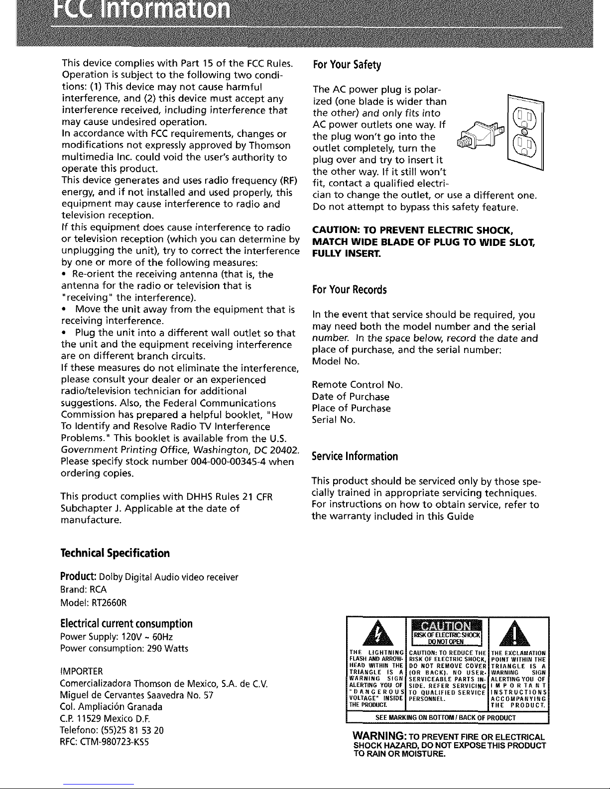
A
THE LIGHTNING
FLASH AND ARROW-
HEAD WITHIN THE
TRIANGLE IS A
WARRING SIGN
ALERTING YOU OF
_RANGEROUS
VOLTAGE" INSIRE
THE PRODUCT,
CAUTION: TO REDUCE THE
RISK OF ELECTRIC SHOCK,
DO NOT REMOVE COVER
(OR DAGK), NO USER.
SERVICEABLE PARTS IN*
SIRE. REFER SERVICIN_
TO QUALIFIED SERVICE
PERSONNEL.
THE EXCLAMATION
POINT WITHIN THE
TRIANGLE IS A
WARNING SIGN
ALERTINGYOU OF
IMPORTANT
INSTRUCTIONS
ACCOMPANYING
THE PRODUCT.
SEEMARKING ON BOTTOM/BACK OF PRODUCT
WARNING: TO PREVENT FIRE OR ELECTRICAL
SHOCK HAZARD, DO NOT EXPOSETHIS PRODUCT
TO RAIN OR MOISTURE.
Page 3
FCC Information
Getting Started
Unpacking the Receiver ............. 2
Inserting Batteries into Remote Control .3
Set Up and Maintenance of the
Receiver .......................... 3
Protect your Components from
Overheating ....................... 3
Connecting to Audio-Visual
Components ...................... 4
Digital Connection ................. 5
Component Connections ............. 5
Connecting Antennas ............... 5
Connecting the Speakers ............. 6
Connecting the Subwoofer ........... 6
Positioning your Speaker ............. 7
Front Speaker Placement ............. 7
Preferred Surround Placement ........ 8
Advanced Surround Setting .......... 8
Test Tone / Channel Balance .......... 9
Connecting for Power ............... 9
Using Headphones .................. 9
Factory Setting ..................... 9
Ooeratina your Receiver
Receiver Controls .................. 10
Your Remote Control ............... 11
Display .......................... 12
Switching OnlOff .................. 13
Show and Hide Control Panel ........ 13
Selection of AudiolVideo Source ...... 13
Using the Remote to Control Additional
Components ...................... 14
Using the receiver to play a Source .... 15
Operating the Radio ............... 16
Advanced Sound Control
Sound Enhancement Systems ........ 19
Fine Setting of Components ......... 21
Speaker Configurations ............. 22
Fine Setting of the Speakers ......... 24
Troubleshooting Tips
Troubleshooting Tips ............... 25
Receiver/Tuner Operation .......... 25
Remote Control Operation ......... 25
General ........................ 25
Cleaning the Exterior ............. 25
Equipment Specifications .......... 25
Care and Maintenance 26
Remote Codes ............... 27
Cable Codes ...................... 27
VCR Codes ....................... 27
TV Codes ........................ 28
Satellite Receivers ................. 29
Audio (RCA only) .................. 29
Laser disc Players .................. 29
Limited Warranty (U.S.) ........ 30
Limited Warranty (Canada) ..... 31
Page 4
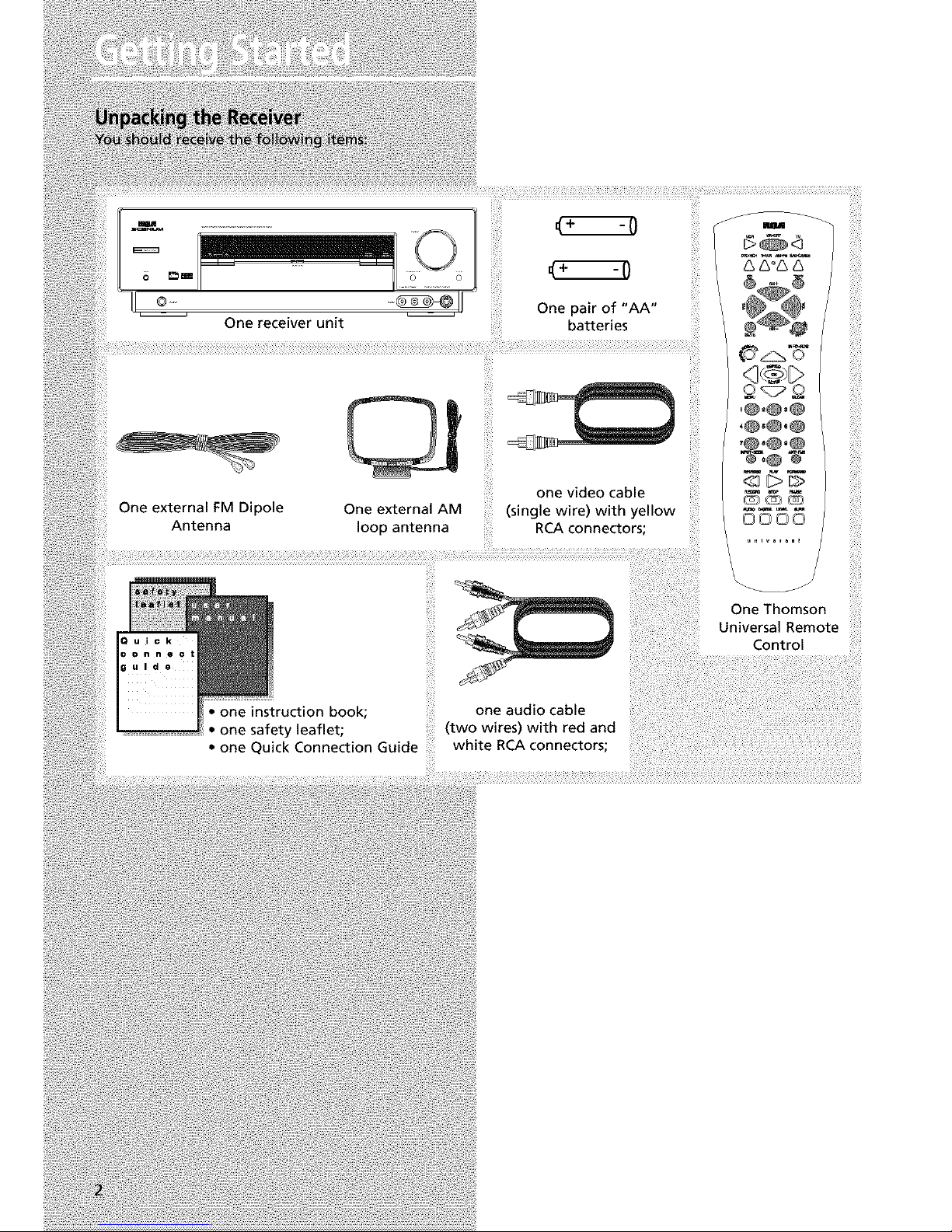
One receiver unit
One external FM Dipole
Antenna
One external AM
loop antenna
-0
(+ -7
One pair of "AA"
batteries
one video cable
(single wire) with yellow
RCA connectors;
(3000
3¸¸:}¸¸
_i'i}!iiiii!
i{{iiiii
{_iii_!ii!i
one audio cable
: one instruction book; (two wires) with red and
onesafetyleaflet;
• one Quick Connection Guide white RCA connectors;
OneThomson
UniversalRemote
Control
Page 5
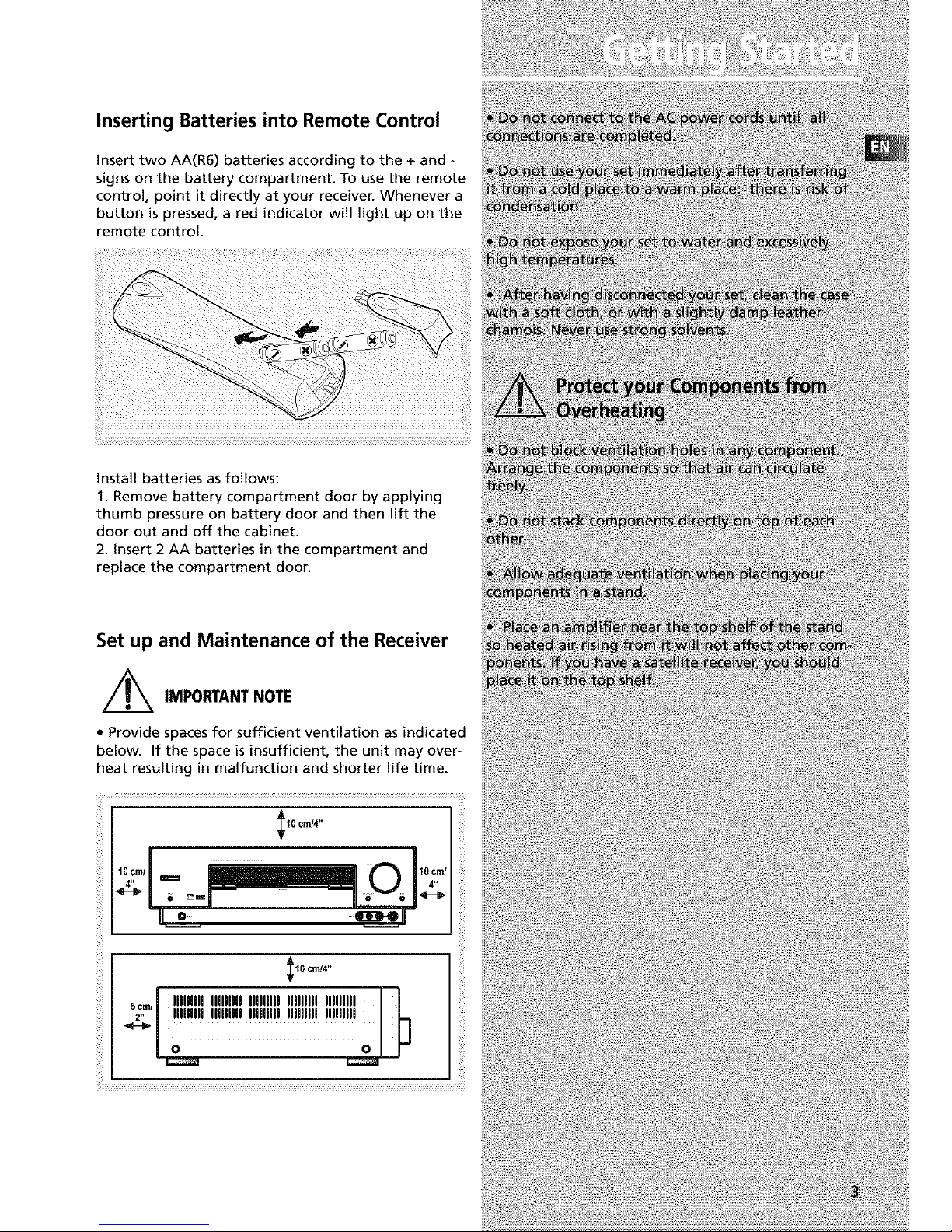
Inserting Batteries into Remote Control
insert two AA(R6) batteries according to the + and -
signs on the battery compartment. To use the remote
control, point it directly at your receiver. Whenever a
button is pressed, a red indicator will light up on the
remote control.
install batteries as follows:
1. Remove battery compartment door by applying
thumb pressure on battery door and then lift the
door out and off the cabinet.
2. insert 2 AA batteries in the compartment and
replace the compartment door.
Set up and Maintenance of the Receiver
,/_ IMPORTANTNOTE
• Provide spaces for sufficient ventilation as indicated
below. If the space is insufficient, the unit may over-
heat resulting in malfunction and shorter life time.
I10 cmi4"
o= .....
10 cnd4"
_l IlJflflll IlflllJfl Ilflfllll Iflflllll llllfllJl |
Page 6
Page 7
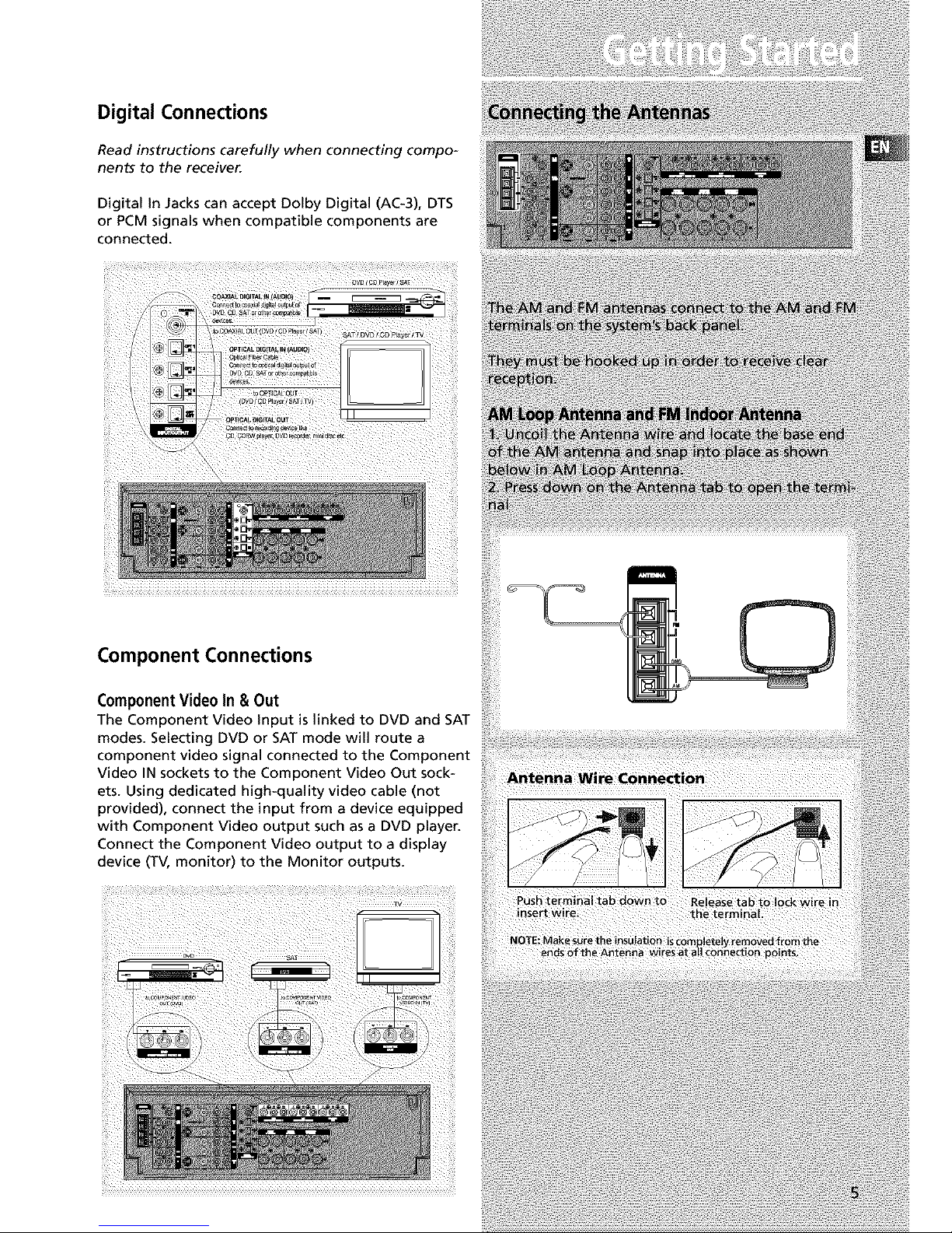
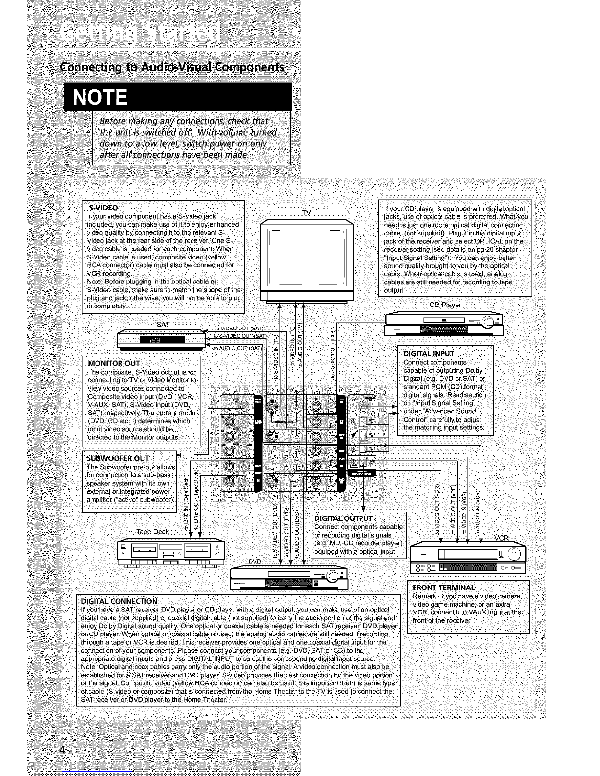
Digital Connections
Read instructions carefully when connecting compo-
nents to the receiver.
Digital in Jacks can accept Dolby Digital (AC-3), DTS
or PCM signals when compatible components are
connected.
Component Connections
ComponentVideo In & Out
The Component Video input is linked to DVD and SAT
modes. Selecting DVD or SAT mode will route a
component video signal connected to the Component
Video IN sockets to the Component Video Out sock-
ets. Using dedicated high-quality video cable (not
provided), connect the input from a device equipped
with Component Video output such as a DVD player.
Connect the Component Video output to a display
device (TV, monitor) to the Monitor outputs.
Page 8
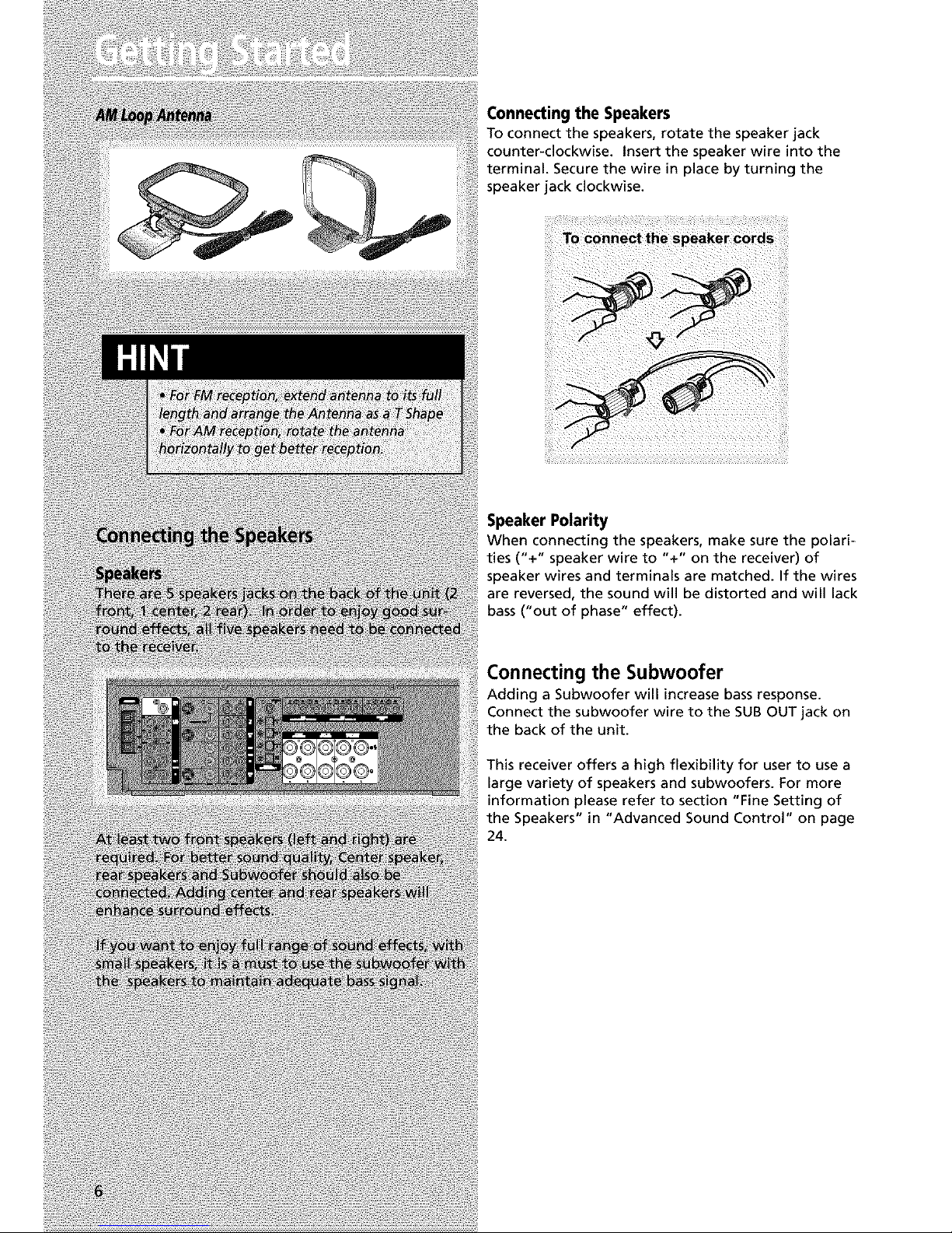
Connecting the Speakers
To connect the speakers, rotate the speaker jack
counter-clockwise. Insert the speaker wire into the
terminal. Secure the wire in place by turning the
speaker jack clockwise.
Speaker Polarity
When connecting the speakers, make sure the polari-
ties ("+" speaker wire to "+" on the receiver) of
speaker wires and terminals are matched. If the wires
are reversed, the sound will be distorted and will lack
bass ("out of phase" effect).
Connecting the Subwoofer
Adding a Subwoofer will increase bass response.
Connect the subwoofer wire to the SUB OUT jack on
the back of the unit.
This receiver offers a high flexibility for user to use a
large variety of speakers and subwoofers. For more
information please refer to section "Fine Setting of
the Speakers" in "Advanced Sound Control" on page
24.
Page 9
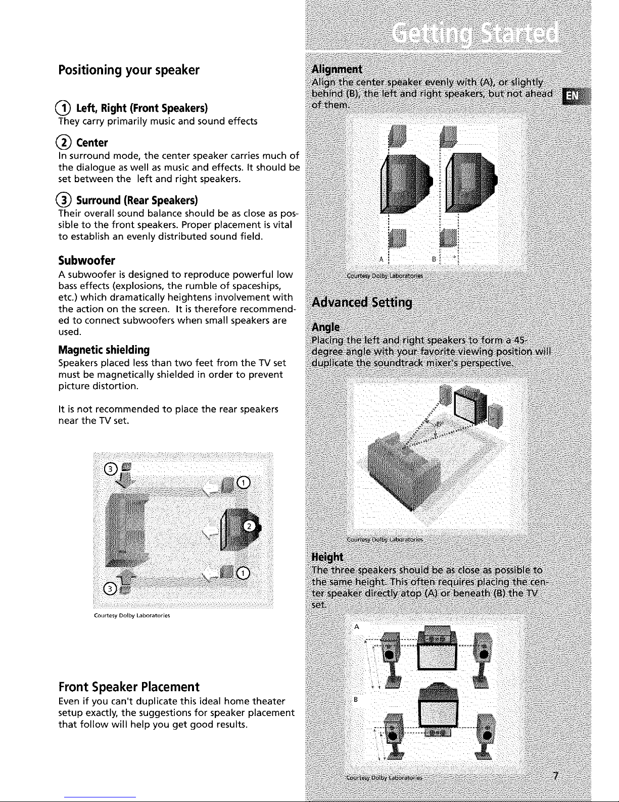
Positioning your speaker
(_ Left, Right (Front Speakers)
They carry primarily music and sound effects
(_ Center
In surround mode, the center speaker carries much of
the dialogue as well as music and effects, it should be
set between the left and right speakers.
(_ Surround (Rear Speakers)
Their overall sound balance should be as close as pos-
sible to the front speakers. Proper placement is vital
to establish an evenly distributed sound field.
Subwoofer
A subwoofer is designed to reproduce powerful low
bass effects (explosions, the rumble of spaceships,
etc.) which dramatically heightens involvement with
the action on the screen. It is therefore recommend-
ed to connect subwoofers when small speakers are
used.
Magnetic shielding
Speakers placed lessthan two feet from the TV set
must be magnetically shielded in order to prevent
picture distortion.
It is not recommended to place the rear speakers
near the TV set.
Courtesy Dolby Laboratories
Front Speaker Placement
Even if you can't duplicate this ideal home theater
setup exactly, the suggestions for speaker placement
that follow will help you get good results.
Page 10
Advanced Setting
Alternative Surround Placement
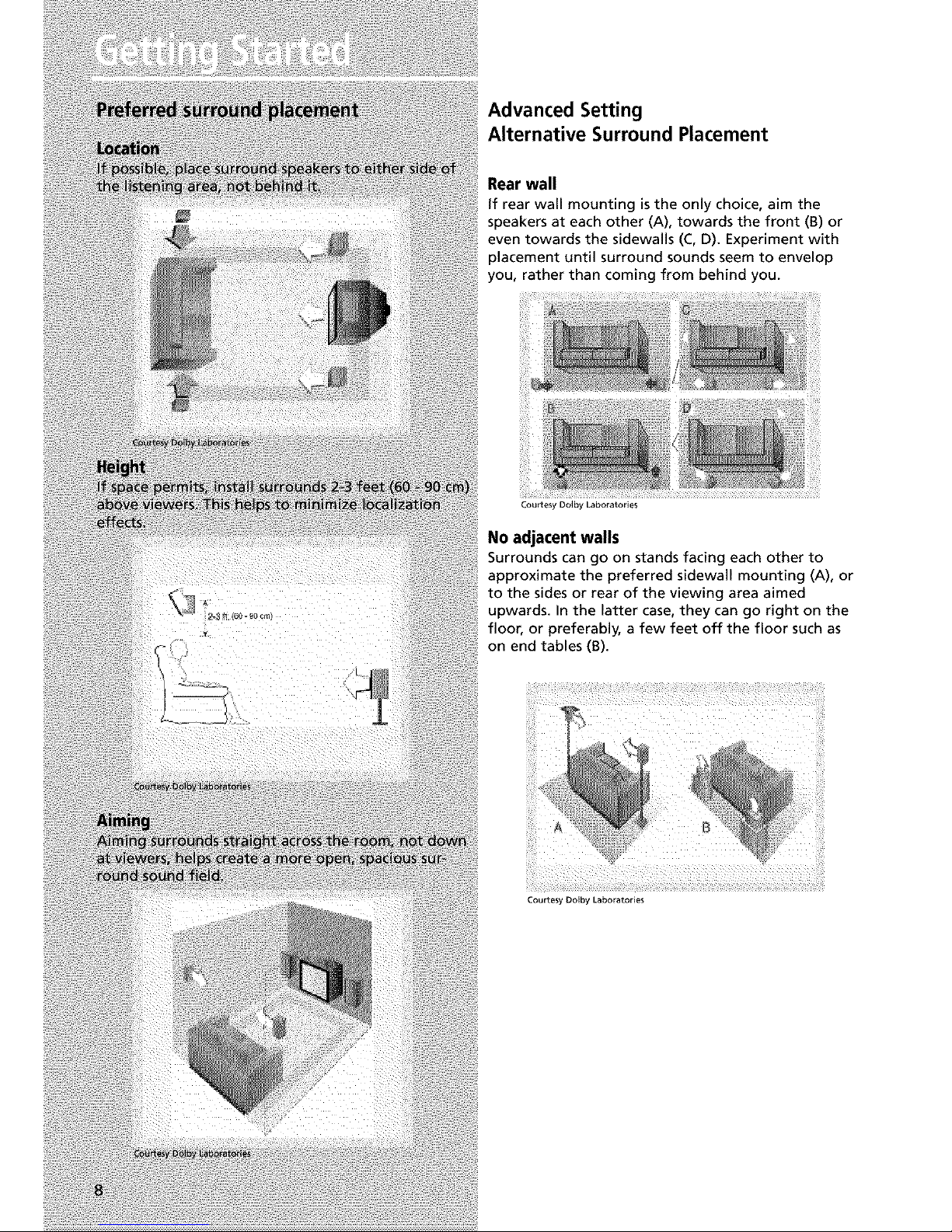
Rear wall
if rear wall mounting isthe only choice, aim the
speakers at each other (A), towards the front (B) or
even towards the sidewalls (C, D). Experiment with
placement until surround sounds seem to envelop
you, rather than coming from behind you.
Courtesy Do,by Laboratories
No adjacent walls
Surrounds can go on stands facing each other to
approximate the preferred sidewall mounting (A), or
to the sides or rear of the viewing area aimed
upwards. In the latter case, they can go right on the
floor, or preferably, a few feet off the floor such as
on end tables (B).
Courtesy Dolby Laboratories
Page 11
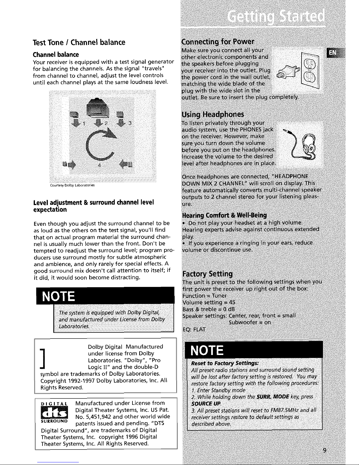
Test Tone / Channel balance
Channel balance
Your receiver is equipped with a test signal generator
for balancing the channels. As the signal "travels"
from channel to channel, adjust the level controls
until each channel plays at the same loudness level.
Courtesy Dolby Laboratories
Level adjustment & surround channel level
expectation
Even though you adjust the surround channel to be
as loud as the others on the test signal, you'll find
that on actual program material the surround chan-
nel is usually much lower than the front. Don't be
tempted to readjust the surround level; program pro-
ducers use surround mostly for subtle atmospheric
and ambience, and only rarely for special effects. A
good surround mix doesn't call attention to itself; if
it did, it would soon become distracting.
Dolby Digital Manufactured
under license from Dolby
Laboratories. "Dolby', "Pro
Logic U" and the double-D
symbol are trademarks of Dolby Laboratories.
Copyright 1992-1997 Dolby Laboratories, Inc. All
Rights Reserved.
D I GI TAL Manufactured under License from
Digital Theater Systems, Inc. US Pat.
No. 5,451,942 and other world wide
SURROUND patents issued and pending. "DTS
Digital Surround", are trademarks of Digital
Theater Systems, Inc. copyright 1996 Digital
Theater Systems, Inc. All Rights Reserved.
Page 12

[][]
II
vAux
I
• Press OK when DIMMER is displayed when scrolllng the Setup
menu to set dlsplay brightness. Use the arrow keys to select
among 4 dimmer levels. Press ok to confirm your setting.
9. TUNING
Press for about 2 seconds to search prevlous / next station in
descendlng / ascendlng frequency direction.
_n Preset mode, press to revlew all preset stations.
_nTuner mode, press to increase/decrease tuner frequencies.
10. SURR. MODE
This button selects DOLBY SURROUND modes (i.e. PLll MOVIE,
PLII MUSIC, Pro Logic) for Do[by Diglta[ 2CH / PCM stereo /
Analog inputs. With 5.1 DoIby Digital or DTS inputs, this but-
ton toggles output between 2 *channel down-mlx mode and
5.1 mode respectively. This button does not response with
other audio input configurations other than the ones men-
tioned above. Press repeatedly to select the surround mode
you want. ( refer to "Advanced Sound Control" on page 21)
lt. MEMORY
Pressto toggle between manual tuning mode and preset sta-
tion mode, Pressand hold to manually store tuner stationin
preset mode. (Referto pg 17 for details)
12. FM/AM
• Pressing the FM/AM button directly changes the active AVR
mode to tuner mode.
• Press to choose between FM/AM in TUNER mode.
• Holding this button continuously starts auto preset station
programming that tunes from FM to the lowest frequency
radio band and stores any tuned frequencies to the preset sta-
tion location until elther all radio bands are scanned or all pre-
set station locations are stored.
13. TEST TONE
When pressing it briefly, a short noise (test tone) will be gener*
ated in the speakers one by one so that you can adjust the vol-
ume of indlvldual speaker. (See page 24 for details)
14. EQ
• With down-m_xed 2 CH / PCM stereo / Analog inputs and 2
channels output only, this button allows the selection of differ-
ent equalizer to be applied to the audio output.
• Press repeatedly to select the desirable EQ mode (music style)
- FLAT, ROCK, POP, JAZZ, CLASSIC, VOCAL. Your choice will be
saved automatlcaliy.(Oniy available in Stereo mode)
15. DIGITAL INPUT/ ST / M
Press repeatedly to select the input device (analog / optlcaI /
optlca[ 2 / optlca[ 3 / coaxial), in FM mode, press to toggle
between stereo and mono.
16. V-AUX Input and S-VIDEO
For convenient use of your dlgltaI camera, family game
machines, second VCR, etc.
17. OPEN/CLOSE
Shows and hides the control panel when the unit is powered
on.
Page 13

Your Remote Control
Please be sure you have inserted the batteries into the
remote control (see relevant section on page 3.) You can
test it by pressing any button. If it works, the red LED
will light.
1. ON/OFF
Page 14

COAX
• Coaxial digital input selected.
STEREO
• Tuner stereo signal detected.
TUNED
• Tuner station detected.
SLEEP
• Unit in Sleep mode.
EQ
• EQ effect activated.
KHz / MHz
• Tuner frequency unit.
• Speakerlcons.
Page 15

Switching on/off
• To enter Standby Mode, press the ON/STANDBY
button once.
• To power on the unit from Standby Mode, press
SOURCE _= or _ button on the main unit or
one of the source buttons on the remote control.
• To switch off the unit completely, press the
ON/STANDBY button or unplug the power cord from
the socket.
Show and Hide Control Panel
When the unit is powered on, touch the OPEN/ClOSE
button on the front panel of the unit to show the
control panel. Press again to hide the control panel.
Page 16

Using the Remote to Control Additional
Components
You can set your remote to control other components
(like CD, TV, DVD, TAPE, etc.). What you need is to
encode them in advance (not necessary for recent
RCA & Proscan models).
1. Turn on the component to be programmed.
2. Look up the brand and corresponding code num-
ber in the code list from page 27 to 29.
3. Press and hold the corresponding Source Button
(like VCR, 113/,DVD) on the remote while entering
the code from the code list using the Number
Buttons.
4. Release the compo-
nent button, then press
ON,OFF to see if the
component will turn off.
5. If this does not work, repeat steps 3 and 4 by try-
ing to use the next code (if available) listed for the
brand of your component until the component
responds to the remote command.
Page 17

Page 18

5-Tune the stations by pressing TUNING UP or
DOWN on the main unit or REVERSE or FORWARD
on the remote control repeatedly until the desired
station is found.
Alternatively, you can press and hold the respective
buttons for about one second to activate the
automatic SEARCH function, in this mode the receiver
will automatically tune frequencies until it finds a
station
Select sound effect if needed by pressing Preset EQ or
DSP sound (see "Advance sound section" for details).
Selecting Mono or Stereo Sound
Press ST/M on the main unit or the DIGITAL button
on the remote control to toggle between mono and
stereo sound in FM tuner mode (when available).
Page 19

Storing radio stations:
The receiver can store up to 40 radio stations in
memory. You can enter every single radio station
yourself or the receiver can store all available radio
station automatically in an ascending order.
Automatic preset storing
1. Select the band by pressing FM/AM on the main
unit or AMeFM on the remote control.
2- Press and hold
FM/AM on the main
unit for 3 seconds.
"MEMORY" will be dis-
played in red and wiU
blink during the auto-
matic storing process.
Radio frequencies wiU be scanned and radio station
stored automatically. When all available radio
stations are stored or if all 40 memory locations are
full, the auto preset will stop.
Page 20

6 Channelexternalinput
An external decoder (Dts, Dolby Digital, etc...) or a
device with built-in multi-channel decoder and 6
channel output connector (DVD player, TV...) can be
connected to the 6CH input. It istherefore possible
to play any future 6 Channels coding (For example,
SACD, DVD Audio) thanks to this connection. The
external decoder device will send the separated
audio information to the receiver that will then
amplify the signal and send to appropriate speakers.
To activate 6 Channel external input, press the
SOURCE _or _ on the receiver until 6 CH is
selected or press DVDe6CH twice on the remote
control.
Page 21

Sound Enhancement Systems
This rece'lver is equipped with several built-in sound
enhancement systems.
Dolby Pro Logic 11
The Pro Logic II mode uses the built-in circuit to steer the
Left, Center, Right and Surround left and right channel
audio signals and uses all five speakers to play both stereo
and Dolby Pro Logic program source, such as TV and VCR.
Do'by Pro Logic I| includes Dolby Pro Logic |I Movie, Dolby
Pro Logic II Music and Dolby Pro Logic.
Use this mode to suit the type of program (such as VCR).
Page 22

When using the remote control, press SETUP key to
access the setup menu. Use the Left and Right arrow
setup keys until EQ MODE is displayed. Press OK to
enter EQ menu. Use the UP and Down setup arrows
to toggle among EQ selections and press OK to con-
firm.
Dolby ProLogic 11
To provide a an exciting experience while listening to
music, DPL II provides several advanced setting to
adjust the DPLII Music mode. By modifying the set-
tings, you will be able to adjust the music output
effect according to different Home Theater set up,
recordings and to suit better your personal tastes. The
3 options are Panorama, Dimension and Center
Width.
Dimension control:
Adjust the balance between the rear and front speak-
ers. Depending on the recordings, the sound may be
focused too much on the front or on the rear speak-
ers. Adjusting this parameter will allow a more bal-
ance sound field.
Center width control:
Control the "weight" or sense of image width of the
sound coming from the center speaker. By adjusting
the variable setting, the sound can only come from
the center speaker or could be progressively blended
into the 2 front speakers.
Panorama mode:
increase the front stereo imaging by using the rear
speakers to increase the surround and "wraparound"
effect. Select "on" to enable Panorama mode.
To access this setup, press the following sequence:
1. Press SETUP on the main unit to access the Setup
menu.
Page 23

2.Pressarrowkeysto scrolltheSetupmenuuntil
DPLHMUSICappearson thedisplay.PressOKto
enterDPU1setup.
3.UsetheUporDownarrowkeysto selectthedesire
optionto set(panorama,dimension,centerwidth).
ThenpressOKto saveyourselection.
Fine Setting of the Components
The receiver has pre-selected surround mode once
you turn on the unit by pressing the Source Buttons
(like DVD, SAT, CD) directly. The default surround
modes for different components are listed in the
table below.
If you decide to change the surround mode, you can
press the SURR MODE button on the main unit or
theater modes on the remote control repeatedly to
toggle among the different surround mode choices
and select the one you want.
PLU MOVIE _ PLU MUSICS" PRO LOGIC _ Stereo
DVD Dolby Digital/DTS PRO LOGIC
SAT Dolby Digital/DTS PRO LOGIC
VCR N/A PRO LOGIC
V-AUX N/A PRO LOGIC
TV Dolby Digital/DTS STEREO
CD STEREO (PCM) STEREO
TAPE N/A STEREO
TUNER N/A STEREO
The receiver will keep the last selection in memory.
Page 24

Usea subwoofer to enjoy optimum sound.
• Subwoofer Phase (SUBW PHASE): Try both settings
and select the sound preferred.
• Speaker distance (DELAY SETUP): For optimum sur-
round experience measure the distance between the
speaker and your favorite listening position.
The receiver has defaulted the following distances:
Front speakers
(L/R) 15 ft
Center speaker
(Cch) 15 ft
Rear speaker
(SUR) 10 ft
Available Setup Selections:
Press SETUP button once to access setup menu.
Use the Up or Down setup arrows to select among:
SLEEP,DIMMER, NIGHT, SPK SETUP, SUBW PHASE, PU[
MUSIC SETUP, DELAY SETUP and EXIT MENU.
Press OK to enter selected category.
Page 25

Speaker Icons
The receiver shows you the speakers' types and set-
tings on the display with the following icons:
Displaying Program Formats
When a digital source is playing, the receiver will
automatically switch to the proper surround mode
and indicates on the speaker icons on the right-hand
side of the display. (See diagram)
Page 26

3.TOadjustindividual speaker volume level, press the
LEVEL button when the short noise is played on the
speaker you want to adjust then adjust the VOLUME
modify the output level.
4. Press LEVEL again to save your setting.
5. Repeat step 3 to adjust other speaker volume lev-
els.
Page 27

Receiver/Tuner Operation
STindicatorisoff.
• Adjust the antenna.
• Press DIGITAL INPUT/ST/MONO button to insure you
are not outputting in mono.
ThesignalisMono.Severehumor noise.
• The signal is too weak. Connect an external antenna.
• Adjust Antenna
• Reposition Antenna away from any electronics.
Remote Control Operation
Theremote controldoesnotoperatetheunit.
• Another source mode is selected on the remote. Press
the correct Source Button.
• No batteries installed. (included with your system)
Install the batteries before attempting to operate the
remote. Be sure to match the + and - ends of each bat-
tery to the symbols shown in the remote battery com-
partment.
• The batteries are weak. Replace all batteries.
• The remote is not pointed at the remote control sen-
sor on the main unit or there is an obstacle between the
remote and the main unit.
• The remote control is too far from the main unit,
move closer.
RemotelosesProgrammedcodes.
• Weak batteries, replace batteries.
Remoteforgetswhat sourcewasselected.
• Weak batteries, replace batteries.
General
Noaudio.
• Make sure the speakers are connected.
• Check the input connections.
• Check the power cord connections.
• Make sure the MUTE signal on the front panel is off.
• Make sure the digital setting (optical, coaxial or ana-
log) is correct.
• Check that the headphone is not inserted.
Noaudiofromonechannel.
• Check the speaker level setting.
• Check the speaker wire or external source cable con-
nections.
Noiseoccurswhenthe TVisturnedon.
• The TV is too close to the audio system.
Specificinstrumentssounddisplaced.
• Check the connections between the receiver and the
speakers if the sound does not match the video.
• Check if the video and audio cable are correctly inserted.
Page 28

Headset safety
• Do not play your headset at a high volume. Hearing
experts warn against extended high-volume play.
• if you experience a ringing in your ears, reduce volume or
discontinue use.
• You should use extreme caution or temporarily
discontinue use in potentially hazardous situations.
• Even if your headset isan open-air type designed to let
you hear outside sounds, don't turn up the volume so high
that you are unable to hear what is around you.
Don't infringe
This product should only be used for the purposes for
which it is sold, that is, entertainment, violating no copy-
right law. Any attempts to use this product for which it is
not intended is unlawful and therefore not condoned by
Thomson multimedia.
Page 29

5002,5003, 5004, 5005, 5006, 5009,5053
5008,5009
5008, 5009, 5010, 5011
5OO8
5OO8
5011
5011
5012, 5013
5014, 5015
5016
5017
5011
5OO9
5018,5019_5049
5OO3
5020, 5021_ 5022, 5035_ 5045
5OO3
5OO2
5011
5003,5005,5007,5018,5023,
5024, 5040_ 5053
5025
5026
5002, 5027, 5028
5002, 5027, 5028
5002, 5016, 5029
5048, 5052
5026
5011, 5012, 5013, 5019, 5025,
5030, 5031, 5032
5033, 5034
5026
5047, 5049, 5052
5009,5049
5022, 5035
5017
5OO3
5020
5014, 5034
5006, 5036, 5037, 5038
5014, 5018
5OO3
5014
5052
5007,5018,5053
5014, 5018
5018
5040
5014
5004,5023,5041
5026
5018
5027
5008,5009,5011
5OO2
5053
5008,5009,5010,5011
5O44
5015, 5025, 5027, 5040
5026, 5050, 5051
Page 30

1172
1001,1173
1174
1016
1002
1046
1038
1003,1038
lOO&1005,1006,1007,1175,1176
1038
1004
1001,1083,1162
1038
1004
lOO&1006,I008,1174
1178
1002
1009
100_1006,I008,1016, 1038, 1105, 1171,
117& 1177
1176
lOO& 1006
lOO& 1006
1012,1013,1014,1038,1176
1038
1038,1171
100_ 1004, 1006, 1018, 1105, 1162, 1171
1038
100_ 1005,1006, 1016, 1017, 1018, 1127,
1171
100_ 1006, 1171
1000
100_ 1181
1178
1002,1176
1003, 1004, 1006, 1019, 1022
lOO& 1006, 1012, 1014, 1023, 102_
1025,1026,1027,1028, 1029,103_
1031,1032,1033,1034, 1035,103& 1037,
1038, 1039, 1041, 1042, 1043, 104& 1046,
1047,1123,1124,1162,1171,117& 1177,
1179,1191
lOO& 1006
1048, 1049, 1050, 1051, 1162, 1180
1046
1038, 1046
1038
100_ 1003, 1004, 1006, 1022, 1052, 1084,
1055,1087,1164,1165,1166,1167,1168,
1181
100_ 1181
lOO& 1005, 1006, 1012, 1019, 105& 1057,
1058,1185,1156,1171,1172
1038, 1046, 1171
lOO& 1006
1038
100_ 1006, 1012, 1013, 1059, 106_ 1061,
1135,1136,1137,1138,1139,114_1141,
1142,1143,1144,1148,1146,1148,1180,
1179
1038
1062
1174
1062
1002
100_ 1004, 1005, 1006, 1008, 1022, 1082,
105_ 1088, 1063, 1064, 1072, 1087, 1105,
1128,1171,1172,1181
100_ 1006
1012, 1013, 1054, 1060, 1065, 106& 1067,
1089, 1187, 1158, 1159, 1182
Page 31

1002,1004,1006
1175
1004,1006,1019
1068,1069,1174,1183
1038,1070,1171,117_1177
1062
1083
I004,1006
I000,I006,1049,1062,1071,1072,1073,
1162,1181
I004,1006,1008,1019,1062,1068,1069,
I074,1075,I076,1077,1088,1089,1130,
1131,1132,1133,113_1183,1184
1083
1062
I004,1006,1062,1078
I006,1059
1176
I001,1006,1082,1083,1162
I004,1005,1006,1019,1022,I051,1079,
I080,I082
I054,1151,1171,1172,1181
1052
I004,1005,I006,1019,1022,1051,1079,
I080,I081,1082,1082,1083,1125
1083
I003,1173
I004,1005,1006,1106,1176,1178
I038,1178
1084
I006,1071,1072,1185
I003,1004,1005,I00_1089
I006,1016
1016
1038
1185
I095,1173
I035,1191
I003,1054,1062,1170
I003,1004,1005,I00_1008,I012,1019,
I062,1068,1069,107_I075,I077,1183,
1184
I003,1004,1008,1012,1019,I062,1068,
I069,1074,1075,I07_I086,1087,1088,
1089
I004,1171
I004,1006,1090,1091,1092,1179,1185
I004,1005,1006,101_1171
1105
1054
I000,1181
I004,1006,1012,1093,1175
1151
1004
I003,1054,1070,I094
I000,1004,1006,1012,1038,I049,1095,
1162,1171,1172
I000,1003,1004,1005,1006,I007,1019,
I096,1098,1099,110_1101,1102,1103,
1129,1179,1181,1187,1188,1190
1176
1151
I004,1006,1171,1172,1175
1004,1005,1006,1012,1015,1019,1104,
1105,1106,1171,1172
1171
1191
1004,1048,1049,105_1080,1107,1108,
1162,1169,1180,1189
1006
1004,1006,1012,102_1036,1038,1046
1000,1004,1006,1013,1019,1046,1048,
1049,1050,1051,106_1071,1072,1109,
1110,1162,1180,1181,1189
1004,1006,1012,1029,1095,1111,1112,
1113,1122,1171,1173
1004
1001,1083,1115
Page 32

Limitation of Warranty:
• THE WARRANTY STATED ABOVE IS THE ONLY WAR-
RANTY APPLICABLE TO THIS PRODUCT. ALL OTHER
WARRANTIES, EXPRESS OR IMPLIED (INCLUDING ALL
IMPLIED WARRANTIES OF MERCHANTABILITY OR FIT-
NESS FOR A PARTICULAR PURPOSE) ARE HEREBY DIS-
CLAIMED. NO VERBAL OR WRITTEN INFORMATION
GIVEN BY THOMSON MULTIMEDIA INC., ITS AGENTS
OR EMPLOYEES SHALL CREATE A GUARANTY OR IN
ANY WAY INCREASE THE SCOPE OF THIS WARRANTY.
• REPAIR OR REPLACEMENT AS PROVIDED UNDER THIS
WARRANTY IS THE EXCLUSIVE REMEDY OF THE CON-
SUMER. THOMSON MULTIMEDIA INC. SHALL NOT BE
LIABLE FOR INCIDENTAL OR CONSEQUENTIAL DAM-
AGES RESULTING FROM THE USE OF THIS PRODUCT OR
ARISING OUT OF ANY BREACH OF ANY EXPRESS OR
IMPLIED WARRANTY ON THIS PRODUCT. THIS DIS-
CLAIMER OF WARRANTIES AND LIMITED WARRANTY
ARE GOVERNED BY THE LAWS OF THE STATE OF INDI-
ANA. EXCEPT TO THE EXTENT PROHIBITED BY APPLIC-
ABLE LAW, ANY IMPLIED WARRANTY OF MER-
CHANTABILITY OR FITNESS FOR A PARTICULAR PUR-
POSE ON THIS PRODUCT IS LIMITED TO THE APPLICA-
BLE WARRANTY PERIOD SET FORTH ABOVE.
How State Law relates to warranty:
• Some states do not allow the exclusion nor limitation of
incidental or consequential damages, or limitations on how
long an implied warranty lasts, so the above limitations or
exclusions may not apply to you.
• This warranty gives you specific legal rights, and you also
may have other rights that vary from state to state.
If you purchased your unit outside the United
States:
• This warranty does not apply. Contact your dealer for
warranty information.
Service calls which do not involve defective materials
or workmanship are not covered by this warranty.
Costs of such service calls are the sole responsibility
of the purchaser.
Page 33

What your warranty covers:
• Defects in materials or workmanship.
For how long after your purchase:
• One year from date of purchase for labor and parts
• The warranty period for rental units begins with the first
rental or 45 days from date of shipment to the rental firm,
whichever comes first.
What we will do:
• Pay any Authorized RCA Audio Service Center the labor
charges to repair your unit.
• Pay any Authorized RCA Audio Service Center for the
new or, at our option, refurbished replacement parts
required to repair your unit.
How you get service:
• Take your unit to any Authorized RCA Audio Service
Center. To identify your nearest Authorized RCA Audio
Service Center, ask your dealer, look in the Yellow Pages, or
call 1-800-336-1900.
• Show the Authorized Service Center Representative your
evidence of purchase date or first rental.
• Pick up your unit when repairs are completed.
• Proof of purchase in the form of a bill of sale or receipt-
ed invoice which is evidence that the product is within the
warranty period must be presented to obtain warranty
service. For rental firms, proof of first rental is also
required.
What your warranty does not cover:
• Customer instruction. (Your Owner's Manual describes
how to install, adjust, and operate your unit. Any addi-
tional information should be obtained from your dealer.)
• Installation and related adjustments.
• Signal reception problems not caused by your unit.
• Damage from misuse or neglect.
• Cleaning of audio heads.
• Batteries.
• A unit that has been modified or incorporated into other
products or is used for institutional or other commercial
purposes.
• A unit purchased or serviced outside Canada.
• Acts of nature, such as but not limited to lightning dam-
age.
Product Registration:
• Please complete and mail the Product Registration Card
packed with your product, it will make it easier to contact
you should it ever be necessary. The return of the card is
not required for warranty coverage.
Page 34

IMPORTADOR
Comercializadora Thomson de Mexico, S.A. de C.V.
Miguel de Cervantes Saavedra 57
Col. Ampliacion Granada
C.P. 11529 Mexico D.E
Telefono: (55)25 81 53 20
R.EC.: CTM-980723-KS5
0151
EXPORTER
Thomson multimedia Inc.
P.O.Box 1976
Indianapolis, IN46206 - 1976
© 2002 Thomson multimedia Inc.
Trademark(s) ® Registered
Marca(s) Registrada(s)
Marque(s) Depos6e
55534520 (EN/F/E)
www.rcascenium.com
www.rca.com/LatinAmerica
Printed in China / Impreso en China
 Loading...