

Page 1
PHD50500 Plasma Monitor User’s Guide
Page 2
Safety Precautions
The following symbols are found on labels
attached to the product. They alert the operators
and service personnel of this equipment to any
potentially dangerous conditions.
IMPORTANT NOTICE
The serial number for this equipment is located on the rear
panel. Please write this serial number on your enclosed
warranty card and keep it in a secure area. This is for your
security.
CAUTION: WHEN POSITIONING THIS EQUIPMENT
ENSURE THAT THE MAINS PLUG AND SOCKET IS EASILY
ACCESSIBLE.
WARNING
This symbol refers to a hazard or unsafe
practice which can result in personal injury
or property damage.
CAUTION
This symbol refers to a hazard or unsafe
practice which can result in severe personal
injury or death.
Product Registration
Please fill out the product registration card (packed separately) and return it immediately. For U.S. customers: Your RCA
Scenium Consumer Electronics product may also be registered at www.rcascenium.com/productregistration. Registering this
product allows us to contact you if needed.
Product Information
Keep your sales receipt to obtain warranty parts and service and for proof of purchase. Attach it here and record the serial and
model numbers in case you need them. The numbers are located on the back of the product.
Model No. _____________________________________________________________________
Serial No. ______________________________________________________________________
Purchase Date: _________________________________________________________________
Dealer/Address/Phone: __________________________________________________________
ii
i
Page 3
Safety Precautions
IMPORTANT SAFETY INSTRUCTIONS
READ INSTRUCTIONS — All the safety and operating
instructions should be read before the product is
operated.
RETAIN INSTRUCTIONS — The safety and operating
instructions should be retained for future
reference.
HEED WARNINGS — All warnings on the product and
in the operating instructions should be adhered to.
FOLLOW INSTRUCTIONS — All operating and use
instructions should be followed.
CLEANING — Unplug this product from the wall outlet
before cleaning. The product should be cleaned
only with a polishing cloth or a soft dry cloth. Never
clean with furniture wax, benzine, insecticides or
other volatile liquids since they may corrode the
cabinet.
ATTACHMENTS — Do not use attachments not
recommended by the product manufacturer as
they may cause hazards.
WATER AND MOISTURE — Do not use this product
near water — for example, near a bathtub, wash
bowl, kitchen sink, or laundry tub; in a wet
basement; or near a swimming pool; and the like.
ACCESSORIES — Do not place this product on an
unstable cart, stand, tripod, bracket, or table. The
product may fall, causing serious injury to a child
or adult, and serious damage to the product. Use
only with a cart, stand, tripod, bracket, or table
recommended by the manufacturer, or sold with
the product. Any mounting of the product should
follow the manufacturer’s instructions, and should
use a mounting accessory recommended by the
manufacturer.
CART — A product and cart combination should be
moved with care. Quick stops, excessive force,
and uneven surfaces may cause the product and
cart combination to overturn.
VENTILATION — Slots and openings in the cabinet
are provided for ventilation and to ensure reliable
operation of the product and to protect it from
overheating, and these openings must not be
blocked or covered. The openings should never
be blocked by placing the product on a bed, sofa,
rug, or other similar surface. This product should
not be placed in a built-in installation such as a
bookcase or rack unless proper ventilation is
provided or the manufacturer’s instructions have
been adhered to.
POWER SOURCES — This product should be operated
only from the type of power source indicated on
the marking label. If you are not sure of the type
of power supply to your home, consult your
product dealer or local power company.
LOCATION — The appliance should be installed in a
stable location.
NONUSE PERIODS — The power cord of the
appliance should be unplugged from the outlet
when left unused for a long period of time.
GROUNDING OR POLARIZATION
÷ If this product is equipped with a polarized
alternating current line plug (a plug having one
blade wider than the other), it will fit into the outlet
only one way. This is a safety feature. If you are
unable to insert the plug fully into the outlet, try
reversing the plug. If the plug should still fail to fit,
contact your electrician to replace your obsolete
outlet. Do not defeat the safety purpose of the
polarized plug.
÷ If this product is equipped with a three-wire
grounding type plug, a plug having a third
(grounding) pin, it will only fit into a grounding type
power outlet. This is a safety feature. If you are
unable to insert the plug into the outlet, contact
your electrician to replace your obsolete outlet. Do
not defeat the safety purpose of the grounding
type plug.
POWER-CORD PROTECTION — Power-supply cords
should be routed so that they are not likely to be
walked on or pinched by items placed upon or
against them, paying particular attention to cords
at plugs, convenience receptacles, and the point
where they exit from the product.
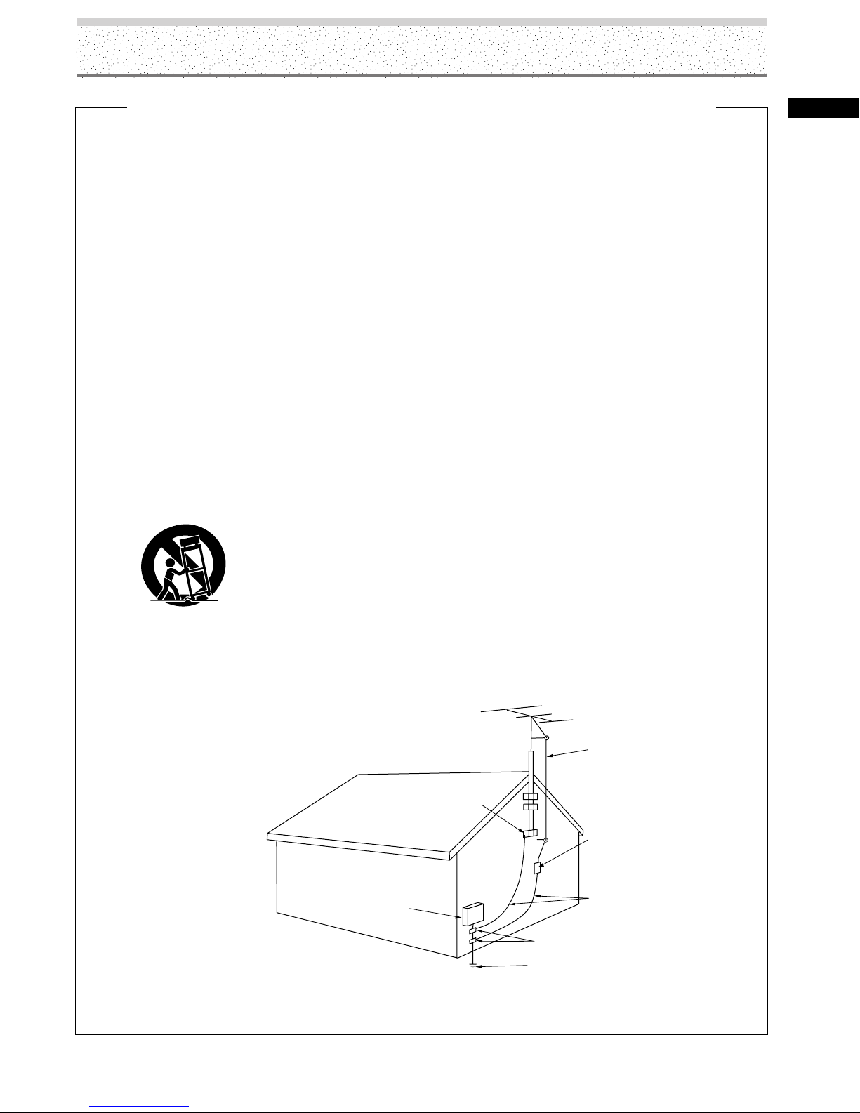
OUTDOOR ANTENNA GROUNDING — If an outside
antenna or cable system is connected to the
product, be sure the antenna or cable system is
grounded so as to provide some protection against
voltage surges and built-up static charges. Article
810 of the National Electrical Code, ANSI/NFPA
70, provides information with regard to proper
grounding of the mast and supporting structure,
grounding of the lead-in wire to an antenna
discharge unit, size of grounding conductors,
location of antenna-discharge unit, connection to
grounding electrodes, and requirements for the
grounding electrode. See Figure A.
LIGHTNING — For added protection for this product
during a lightning storm, or when it is left
unattended and unused for long periods of time,
unplug it from the wall outlet and disconnect the
antenna or cable system. This will prevent damage
to the product due to lightning and power-line
surges.
POWER LINES — An outside antenna system should
not be located in the vicinity of overhead power
lines or other electric light or power circuits, or
where it can fall into such power lines or circuits.
When installing an outside antenna system,
extreme care should be taken to keep from
touching such power lines or circuits as contact
with them might be fatal.
OVERLOADING — Do not overload wall outlets,
extension cords, or integral convenience
receptacles as this can result in a risk of fire or
electric shock.
GROUND
CLAMP
OBJECT AND LIQUID ENTRY — Never push objects
of any kind into this product through openings as
they may touch dangerous voltage points or shortout parts that could result in a fire or electric shock.
Never spill liquid of any kind on the product.
SERVICING — Do not attempt to service this product
yourself as opening or removing covers may
expose you to dangerous voltage or other hazards.
Refer all servicing to qualified service personnel.
DAMAGE REQUIRING SERVICE — Unplug this
product from the wall outlet and refer servicing to
qualified service personnel under the following
conditions:
÷ When the power-supply cord or plug is damaged.
÷ If liquid has been spilled, or objects have fallen
into the product.
÷ If the product has been exposed to rain or water.
÷ If the product does not operate normally by
following the operating instructions. Adjust only
those controls that are covered by the operating
instructions as an improper adjustment of other
controls may result in damage and will often
require extensive work by a qualified technician to
restore the product to its normal operation.
÷ If the product has been dropped or damaged in
any way.
÷ When the product exhibits a distinct change in
performance — this indicates a need for service.
REPLACEMENT PARTS — When replacement parts
are required, be sure the service technician has
used replacement parts specified by the
manufacturer or have the same characteristics as
the original part. Unauthorized substitutions may
result in fire, electric shock, or other hazards.
SAFETY CHECK — Upon completion of any service
or repairs to this product, ask the service technician
to perform safety checks to determine that the
product is in proper operating condition.
HEAT — The product should be situated away from
heat sources such as radiators, heat registers,
stoves, or other products (including amplifiers) that
produce heat.
WALL OR CEILING MOUNTING — The product
should be mounted to a wall or ceiling only as
recommended by the manufacturer.
ANTENNA
LEAD IN
WIRE
ANTENNA
DISCHARGE UNIT
(NEC SECTION 810-20)
Safety Precautions
ELECTRIC
SERVICE
EQUIPMENT
Figure A
GROUNDING CONDUCTORS
(NEC SECTION 810-21)
GROUND CLAMPS
POWER SERVICE GROUNDING
ELECTRODE SYSTEM
(NEC ART 250, PART H)
NEC – NATIONAL ELECTRICAL CODE
iii
ii
Page 4

This page intentionally left blank.
Page 5

Table of Contents
Before Proceeding
How to Use This Manual .................. 2
How to Use the Menus ....................................... 4
Checking Supplied Parts .................. 4
Part Names and Functions
Main Unit ........................................... 5
Connection Panel .............................. 6
A Quick Tour of the Remote Control
The Remote Control.......................... 8
Button Descriptions for Monitor Mode ............. 8
Button Descriptions for Other Components ..... 9
Using Your Remote Control ............................. 10
Programming the Remote................................ 10
Find Out if You Need to Program the
Remote ........................................................... 10
How to Program the Remote ........................... 11
How to Use the Remote Control After
You’ve Programmed It .................................. 12
Programmable Codes for
the Remote Control ..................... 13
Setting Up the System
Setup after Connection .................. 25
Setting the Screen Mode/ Input Signal
Format ............................................................ 25
CLAMP POSITION Setup .................................. 26
Operations
Selecting an Input Source .............. 27
To Adjust the Volume ....................................... 28
To Mute the Sound ........................................... 28
To Confirm Display Settings ............................ 28
Screen Size Selection ..................... 29
Changing the Screen Size ................................ 29
Moving the Screen Position Upward or
Downward ...................................................... 29
Automatic Screen Size ..................................... 29
Partial Image Enlargement
(Zoom) ......................................... 30
Automatic Power OFF .................... 31
Monitor Panel Adjustments
Adjusting the Picture Quality......... 32
Installation and Connections
Installation of the Unit.................... 15
About the Input Connectors
on this Unit .................................. 16
Connection to INPUT1 and
INPUT2 ......................................... 16
Connection to AV Components ....................... 16
Connection to a Personal Computer ............... 18
Connection to INPUT3 .................... 20
Connection to INPUT5 .................... 20
Connection to INPUT4 .................... 20
About HDTV Set Top Box
Connection ................................... 21
Audio Connections.......................... 22
Power Cord Connection ................. 24
Monitor Panel Adjustments ........... 32
Adjusting the Image Position
and Clock (Automatic
Adjustment) ................................. 33
Manual Adjustment of Screen
Position and Clock ....................... 33
Other Operations
Changing the Color Temperature
(COLOR TEMP) ............................. 35
Reducing Video Noise
(DIGITAL NR) ................................ 35
Setting the Film Mode .................... 36
Viewing a Fast Moving Picture
(3D Y/C MODE) ............................ 36
Viewing in a Bright Location
(HIGH CONTRAST) ...................... 37
1
Page 6

Table of Contents
Audio Output (AUDIO OUT) ........... 38
Setting the Menu Language .......... 38
Additional Information
Cleaning ......................................... 39
Troubleshooting .............................. 40
Additional Notes and Cautions...... 43
Specifications .................................. 44
Supplement 1 .................................. 45
Supplement 2 .................................. 46
Supplement 3 .................................. 47
Supplement 4 .................................. 47
Explanation of Terms ...................... 47
Limited Warranty ............................ 48
FCC Declaration of Conformity
and Industry Canada
Information .................................. 50
2
Page 7

Before Proceeding
How to Use This Manual
This manual is set up to follow the course of actions and
operations in the order that would seem most logical for
someone setting up this unit.
Once the unit has been taken out of the box, and it has
been confirmed that all the parts have been received, it
may be beneficial to look over the section “Part Names
and Functions” starting on page 5 to become acquainted
with the plasma monitor and remote control unit, as their
respective buttons and controls will be referred to
throughout this manual.
The section “Installation and Connections” starting on
page 15 covers all the necessary points regarding
installation of the plasma monitor and connections to a
wide variety of components.
The section “Setting Up the System” starting on page 25
covers the necessary on-screen menu settings to
establish correct linkage between the plasma monitor and
connected components. Depending on the connections
made, this section may or not be necessary.
The remainder of the sections in this manual is dedicated
to the basic operations associated with selecting a source
component up to the more complex operations
associated with adjusting the plasma monitor picture to
match the requirements of specific components and
personal preferences.
About operations in this manual
Operations in this manual are outlined in step by step
numbered procedures. Most of the procedures are
written in reference to the remote control unit unless the
button or control is only present on the main unit.
However, if a button or control on the main unit has the
same or similar name as that on the remote control unit,
that button can be used when performing operations.
Note
The screen displays depicted in this manual represent typical
display examples.
The actual items and contents seen in screen displays may vary
depending on input source and specific settings.
Apple and Macintosh are registered trademarks of Apple Computer, Inc.
Microsoft is a registered trademark of Microsoft Corporation.
NEC and PC-9800 are trademarks of NEC Corporation.
VESA and DDC are registered trademarks of Video Electronics Standards Association.
Power Management and Sun Microsystems are registered trademarks of Sun Microsystems, Inc.
VGA and XGA are registered trademarks of International Business Machines Co., Inc.
3
Page 8

Before Proceeding
STOP PAUSE
MONITOR
O
N•OFF
A
UX
DVD
SAT•CABLE
RECORD
PLAYFOR
W
ARDREV
ERS
E
AUTO SET
CIN
EM
A
M
UTE
INFO
MENU
OK
CLEAR
GU
IDE
ANTENNA
1
2
3
4
5
6
7
8
9
0
INPUT
VCR
1
A
VCR
2
C
H
+
C
H
–
V
O
L
V
O
L
GO BACK
REPEAT
AUDIO
ANGLE OPEN
Z
O
O
M
u n i v e r s a l
DVD
How to Use the Menus
The following example is an actual operation that shows how
you might set the horizontal and vertical positions of the
screen. The screens shown at each step are provided as a
visual guide to confirm that the procedure is proceeding as it
should. Please familiarize yourself with this process before
continuing with the rest of this manual.
1 Press MENU to display the menu screen.
MAIN MENU INPUT1
PICTURE
CONT RAST
BRIGHTNESS
CO LOR
TINT
SHARPNESS
SET UP
:
:
:
:
:
RSETE
SELECT ENTER EXIT
2 Press to select SCREEN.
MAIN MENU INPUT1
PICTURE
SCREEN
POS I T ION
P
CL OC HAS EK/ /
RSETE
OPTION
0
0
0
0
0
OK
SET UP OPTION
:
00
/
:
00
CLEAR
Checking Supplied Parts
Check that the following parts were supplied.
1 Power cord
2 Remote control
3 AA (R6) batteries ( x 2)
SELECT ENTER EXIT
OK
CLEAR
3 Press / to select the item to be adjusted.
4 Stereo mini to RCA plugs cable
MAIN MENU INPUT1
PICTURE
SCREEN
POS I T ION
P
CL OC HAS EK/ /
RSETE
SET UP OPTION
:
00
/
:
00
5 BNC to RCA phono jack adapters ( x 5)
(may be attached to the back of the monitor)
SELECT ENTER EXIT
OK
CLEAR
4 Press OK to display the adjustment screen for the
selected item.
POH. S I T ION
POV. S I T I ON
5 Press / / / to adjust the value.
4
ADJUS
:
0
:
0
CLEAR
EXI
T
T
O
K
SE
T
Page 9
Main Unit
POWER
4
INPUT
CINEMA
VOLUME ++
Main unit
STANDBY/ON
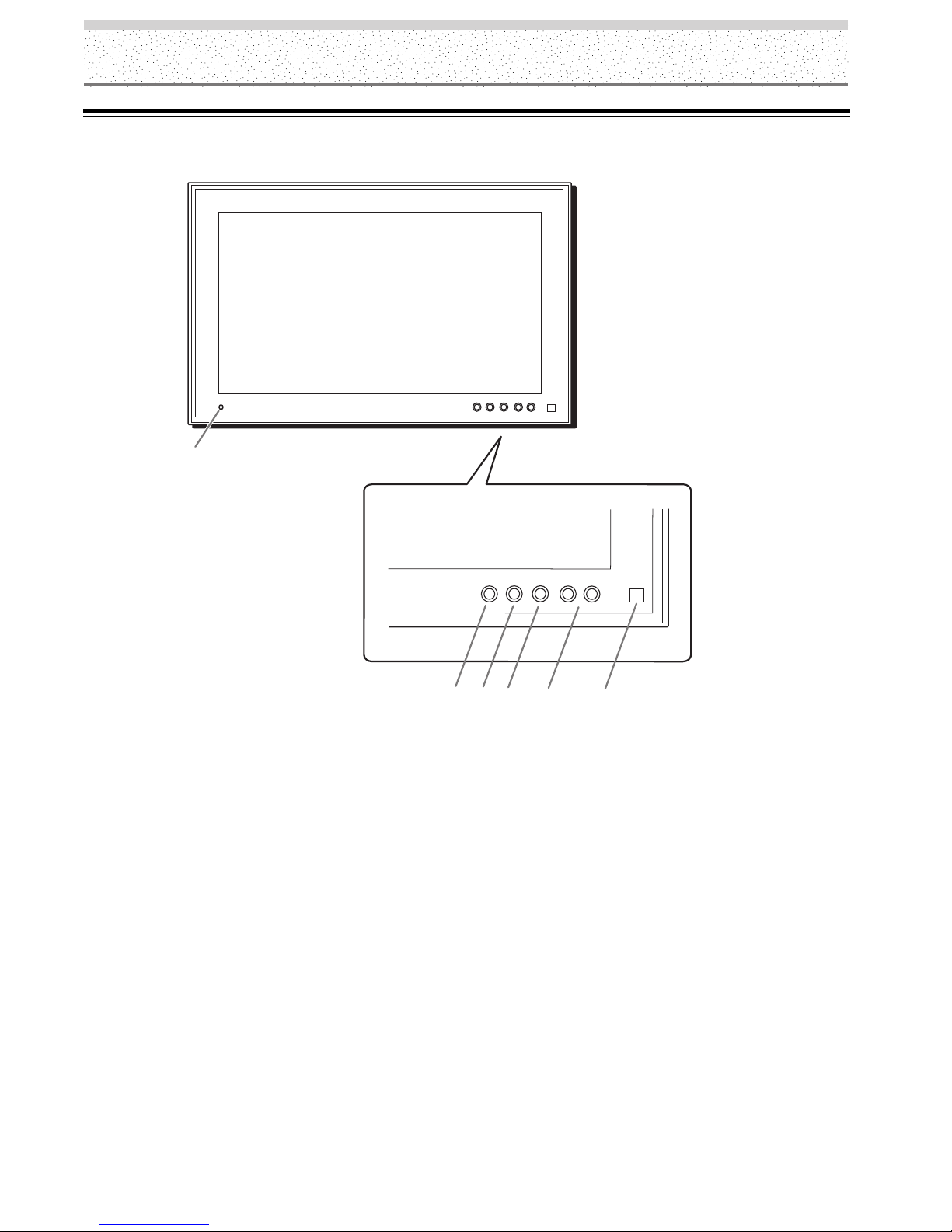
Part Names and Functions
POWER
– VOLUME +
INPUT
CINEMA
1
Front of the Plasma Monitor
1 STANDBY/ON indicator
This indicator is red during standby mode, and turns
to green when the unit is in the operation mode
(page 27).
Flashes green when Power-Management function is
operating (page 31).
The flashing pattern is also used to indicate error
messages (page 43).
2 POWER button
Turns plasma monitor on and off.
2
Operation panel on the main unit
3
POWER
INPUT
CINEMA
5
–– VOLUME
6
4 CINEMA button
Press to select the screen size (page 29).
5 VOLUME –/+ buttons
Press to adjust the volume.
6 Remote control sensor
Point the remote control toward the remote sensor to
operate the unit (page 10)
3 INPUT button
Press to select input (page 27).
5
Page 10

Part Names and Functions
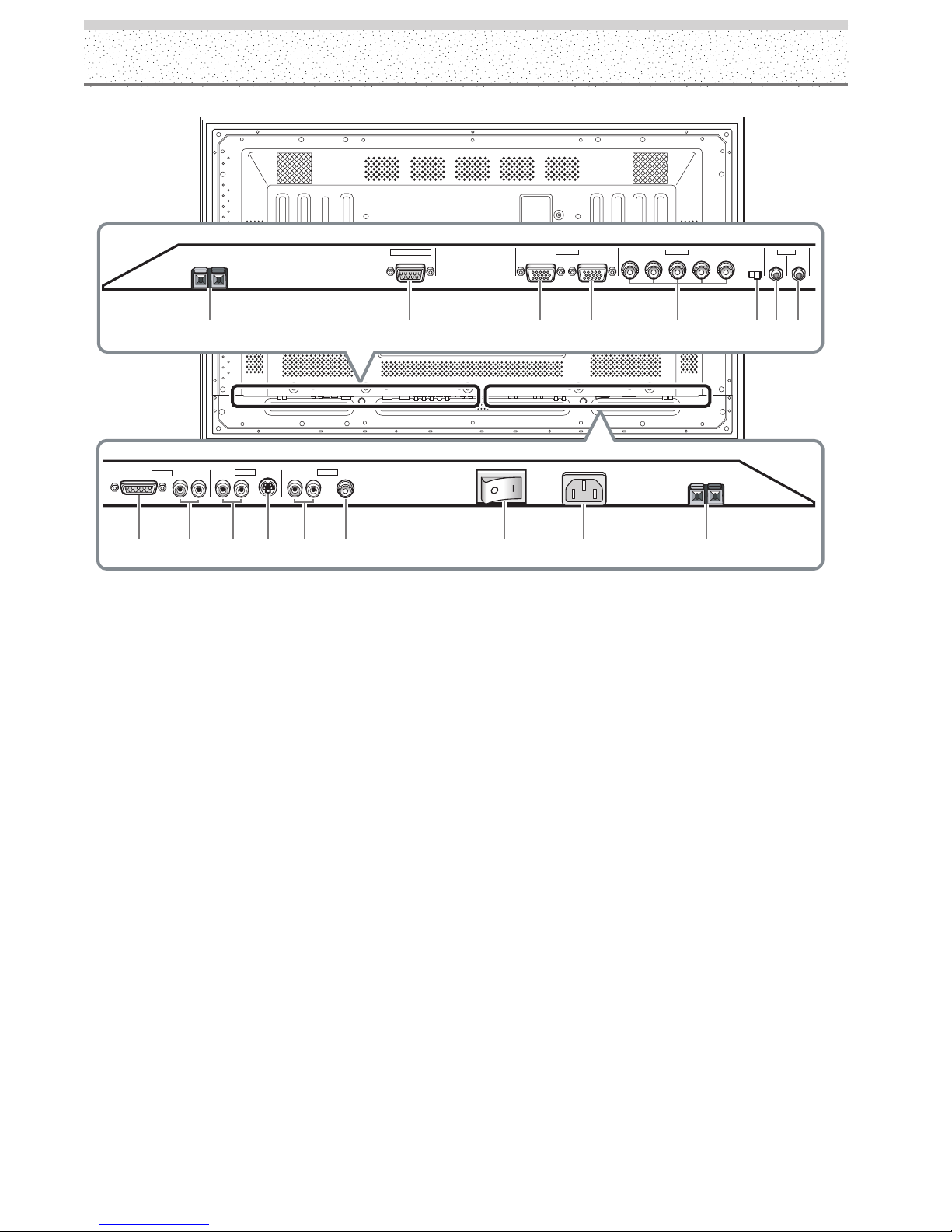
Connection Panel
The connection panel has five video input terminals and
one video output terminal. Audio input and speaker
output terminals are also provided.
For instructions regarding connections, consult the pages
noted in parentheses by each item.
1 SPEAKER (R) terminal
For connecting an external right speaker.
Connect a speaker whose impedance is 8 –16 Ω
(page 22).
2 UPGRADE PORT
DO NOT MAKE ANY CONNECTIONS TO THIS
TERMINAL.
This terminal is used in the factory setup.
3 INPUT1 (mini D-sub 15 pin)
For connection of components that have RGB or
component output jacks such as a personal
computer, HD receiver, DVD player, or external RGB
decoder. Make sure that the connection made
corresponds to the format of the signal output from
the connected component (pages 16-19).
4 OUTPUT (INPUT1) (mini D-sub 15 pin)
Use the OUTPUT (INPUT1) terminal to output the
video signal to an external monitor or other
component.
Note: The video signal will not be output from the OUTPUT
(INPUT1) terminal when the main power of this unit is off or in
standby mode (page 18).
6 Synchronizing signal impedance selector switch
Depending on the connections made at INPUT2, it
may be necessary to set this switch to match the
output impedance of the connected component’s
synchronization signal.
When the output impedance of the component’s
synchronization signal is 75 Ω, set this switch to the
75 Ω position (pages 17-19).
7 AUDIO INPUT (Stereo mini jack)
Use to obtain sound when INPUT1 or INPUT2 is
selected.
Connect the audio output terminal of components
connected to INPUT1 or INPUT2 (page 22).
8 AUDIO OUTPUT (Stereo mini jack)
Use to output the audio of the selected source
component connected to this unit to an AV amplifier
or similar component (page 22). Use the supplied
stereo mini to RCA phono plugs cable.
9 DVI VIDEO INPUT5 (DVI jack)
For connection of components that have a DVI digital
video output terminal such as a video camera,
LaserDisc player, or DVD player (page 20).
0 AUDIO INPUT5 (RCA Pin jacks)
Use to obtain sound when INPUT5 is selected.
Connect these jacks to the audio output connectors of
components connected to INPUT5 (page 23).
Note: The left audio channel (L) jack is not compatible with
monaural input sources.
5 INPUT2 (BNC jacks with RCA jack adapter)
For connection of components that have RGB or
component output jacks such as a personal computer,
DVD player, or external RGB decoder. Make sure that
the connection made corresponds to the format of
the signal output from the connected component
(pages 16-19).
6
Page 11
Part Names and Functions
8Ω ~16Ω
SPEAKER
R
+ –
123 45678
DVI VIDEO
9
INPUT5
AUDIO
R
0
AUDIO
R
L
L
AUDIO
R
L
=-
~
!
S-VIDEO VIDEO
INPUT3 INPUT4
- AUDIO INPUT3 (RCA Pin jacks)
Use to obtain sound when INPUT3 is selected.
Connect these jacks to the audio output connectors of
components connected to INPUT3 (page 22).
Note: The left audio channel (L) jack is not compatible with
monaural input sources.
UPGRADE PORT
OUTPUT
AC INLET
(ON SYNC) (H/V SYNC)
INPUT2 AUDIO
GBRHDVD
8Ω ~16Ω
SPEAKER
+ –
INPUT
(INPUT1/2)
75 2.2
Ô
Ω κΩ
L
INPUT1
ANALOG RGB (ANALOG RGB)
$#@
! INPUT4 (RCA jack)
For connection of components that have a composite
video output terminal such as a video deck, video
camera, LaserDisc player, or DVD player (page 20).
@ Main power switch
Use to switch the main power of the unit on and off.
OUTPUT
= INPUT3 (S-video jack)
For connection of components that have an S-video
output terminal such as a video deck, video camera,
LaserDisc player, or DVD player. (page 20)
~ AUDIO INPUT4 (RCA jacks)
Use to obtain sound when INPUT4 is selected.
Connect these terminals to the audio output
connectors of components connected to INPUT4
(page 23).
Note: The left audio channel (L) jack is not compatible with
monaural input sources.
# AC INLET
Use to connect the supplied power cord to an AC outlet
(page 24).
$ SPEAKER (L) terminal
For connection of an external left speaker. Connect a
speaker that has an impedance of 8 –16 Ω (page 22).
7
Page 12
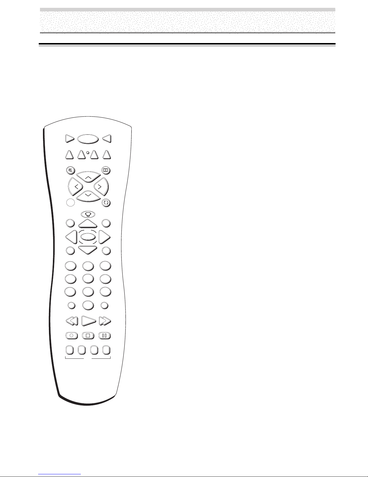
A Quick Tour of the Remote Control
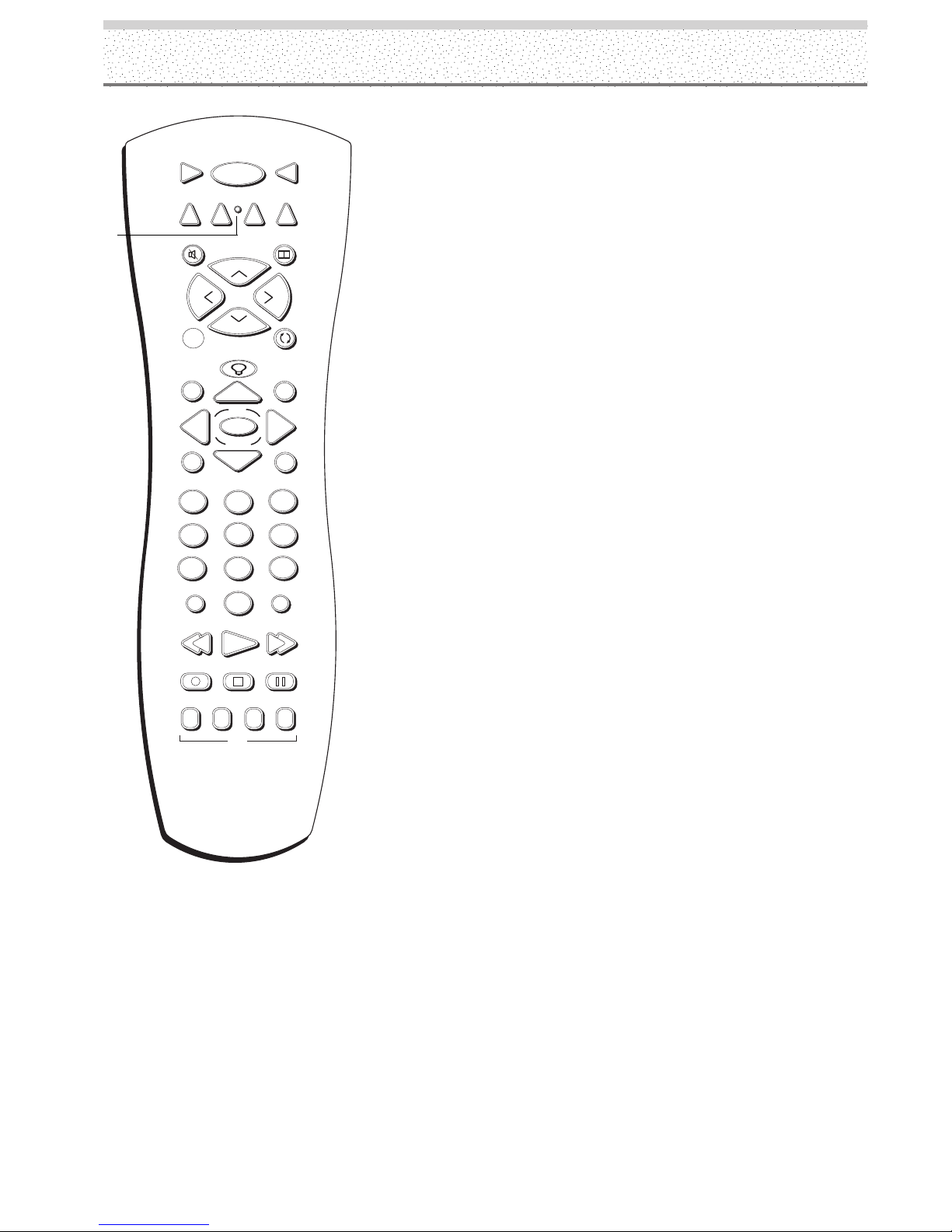
The Remote Control
Button Descriptions for Monitor Mode
In addition to operating your Plasma Monitor, the remote that came with it can operate your other components. However,
this page only describes the buttons on the remote that you will use with your monitor.
For descriptions of remote control buttons to be used with your other components, go to the next page.
In alphabetical order
ON•OFF
VCR
1
DVD
MUTE
L
A
AUTO SET
GUIDE
VCR
O
V
MONITOR
SAT•CABLE
AUX
2
Arrow buttons Use the arrows to navigate through the menu
screens and move the Zoom pointer in Zoom mode.
AUTO SET When using a computer signal input, automatically sets
CINEMA
H
+
C
V
O
L
C
–
H
GO BACK
INFO
OK
the Position and Clock/Phase settings to optimum values.
Backlight Lights up some of the remote buttons in the dark.
CINEMA Selects one of four screen sizes to suit the type of input
you’re watching.
CLEAR Clears on-screen displays and returns you to normal viewing.
INFO Brings up display information.
INPUT Changes the video input.
Z
O
O
M
MENU
2
1
4
5
7
8
INPUT
CLEAR
3
6
9
ANTENNA
0
PLAY FORWARDREVERSE
RECORD
REPEAT
STOP PAUSE
ANGLE OPEN
AUDIO
DVD
u n i v e r s a l
Note: This remote operates most RCA, GE, and
Proscan products.
MENU Brings up the on-screen menu.
MONITOR Turns the power to the monitor on and puts the remote in
Monitor mode so you are able to control the monitor.
MUTE Reduces sound to an inaudible level.
OK/ZOOM When in Monitor mode and using on-screen menus,
press OK to select a highlighted menu function. When there are no
on-screen menus displayed, press OK to bring up the zoom pointer.
Using the arrow buttons, position the pointer on the part of the screen
you want to zoom on, then use the OK/ZOOM button to choose the
zoom ratio.
ON•OFF Toggles power on and off for the components that you have
programmed. For example, if you are in VCR mode, turns VCR on and
off.
VOL< and > buttons Adjust the volume.
8
Page 13
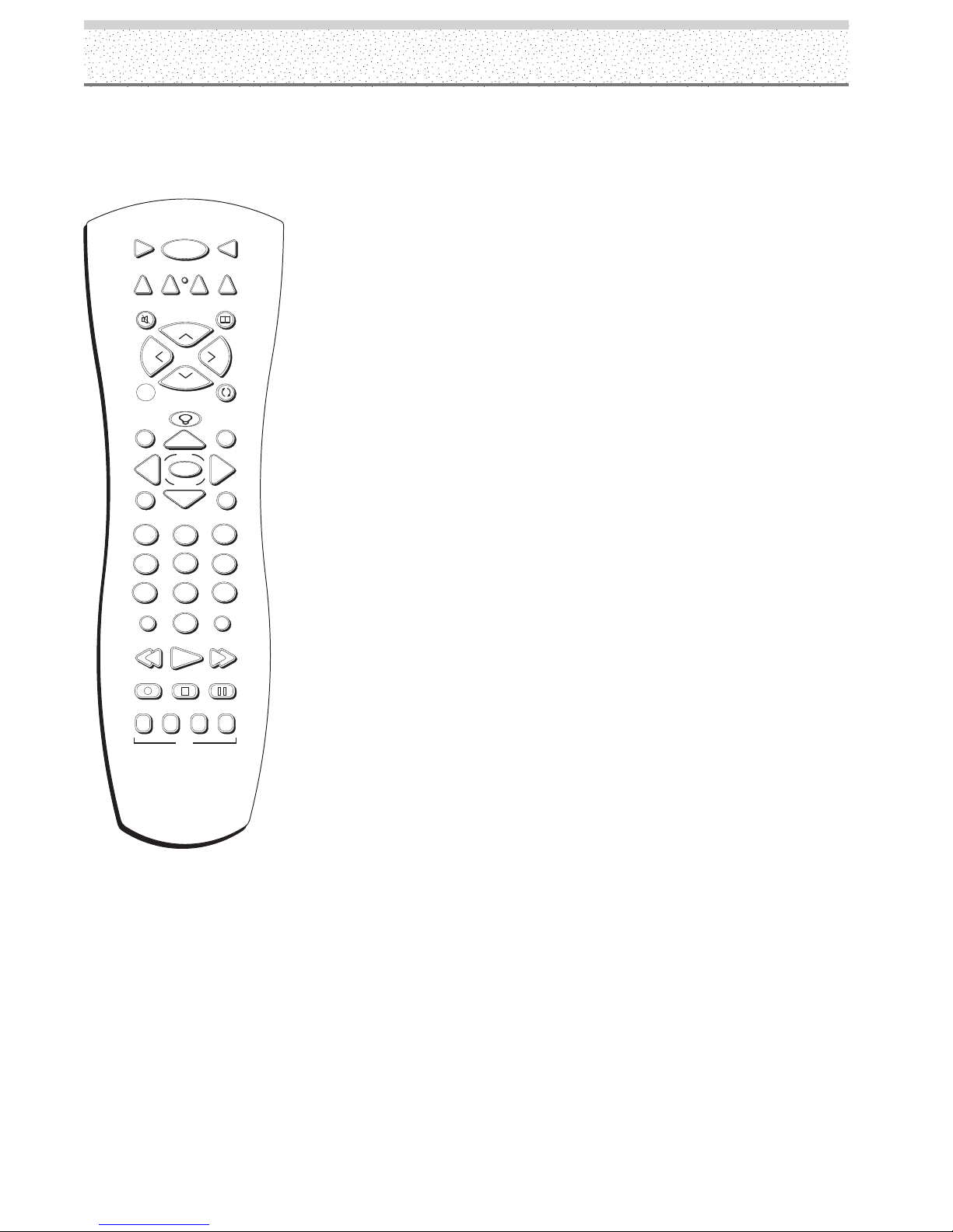
Remote Control
Button Descriptions for Other Components
This remote operates most brands of other components (VCRs, DVD players, satellite receivers, etc). The following list (in
alphabetical order) provides basic information about how these buttons will operate in these modes.
(0-9) Number buttons When the remote is in HD receiver mode (SAT•CABLE
VCR
DVD
ON•OFF
1
VCR
MONITOR
SAT•CABLE
AUX
2
button), select channels up to 99 by pressing two number buttons. Selects 3digit channels by pressing and holding 1 until 1 - - appears on the screen. Then
press the other two numbers.
MUTE
L
O
V
A
AUTO SET
GUIDE
MENU
2
1
4
5
7
8
INPUT
0
RECORD
AUDIO
REPEAT
u n i v e r s a l
CINEMA
H
+
C
C
–
H
GO BACK
OK
Z
O
O
M
CLEAR
3
6
9
ANTENNA
PLAY FORWARDREVERSE
STOP PAUSE
ANGLE OPEN
DVD
V
O
L
INFO
ANGLE Accesses various camera angles when using a compatible RCA, GE, or
Proscan DVD player (if available on the DVD disc).
ANTENNA When the remote is in HD RCVR mode, switches the HD receiver
between Antenna A and Antenna B.
AUDIO Brings up the Audio language info display on a compatible RCA, GE, or
Proscan DVD player.
AUX (auxiliary) You can program this button to control any one of the following:
a cable box; some GE and RCA audio components; a laserdisc player; a VCR; or
a satellite receiver. Press this button to operate the component you’ve
programmed to work with the AUX button.
CH+/CH– buttons Change channels on the HD receiver when the remote is in
HD receiver mode.
DVD Turns on a compatible RCA, GE, or Proscan DVD player and sets the
remote to control the DVD player. Also used with the ON•OFF button to turn on
other compatible DVD players.
FORWARD Fast forwards a tape or searches forward on a DVD disc on a
compatible VCR or DVD player.
GO BACK In HD receiver mode, returns you to the previous channel.
GUIDE In HD receiver mode, brings up the on-screen program guide.
OPEN Opens and closes the DVD disc tray on a compatible DVD player.
PAUSE Pauses playback or recording on a compatible VCR. Pauses a DVD
disc on a DVD player.
PLAY Plays a tape or DVD disc on a compatible VCR or DVD player.
RECORD Starts recording on a compatible VCR.
REPEAT Brings up the Repeat info display on a compatible RCA, GE, or Proscan DVD player. You can repeat
part or all of a title, chapter, or track.
REVERSE Rewinds a tape or searches backward on a DVD disc on a compatible VCR or DVD player.
SAT•CABLE Turns on a compatible RCA, GE, or Proscan satellite receiver or HD receiver, puts the remote in
receiver or cable box mode, and can also be programmed to operate some compatible receivers or cable boxes.
STOP Stops the current function (play, record, reverse, etc.) on a compatible VCR or DVD player.
VCR1 and VCR2 buttons Turn on a compatible RCA, GE, or Proscan VCR and set the remote to control the
VCR. Also used with the ON•OFF button to turn on other compatible VCRs.
9
Page 14

Remote Control
Installing the batteries
Using Your Remote Control
Inserting Batteries
1. Remove the battery compartment cover from the remote
control.
2. Insert batteries (included) as shown on the diagram inside
the battery compartment.
3. Replace the battery compartment cover.
Use your remote control from a distance of about 7m/23 feet
from the monitor’s remote control sensor and at a horizontal
angle of within 30°. The remote operates on line of sight, so if
there is anything blocking the path between the remote and the
remote control sensor on the front of the monitor, the remote
may not work.
• Don’t expose the remote control sensor on the front of the
monitor to direct sunlight or strong artificial light.
• Don’t get the remote control wet.
•Avoid heat and humidity.
POWER
– VOLUME +
INPUT
STANDBY/ON
CINEMA
30°30°
ON OFF
VCR1
MONITOR
SAT CABLE
DVD
VCR2
AUX
WHOMUTE
+
H
C
V
L
O
O
L
V
C
H
-
Z
Z
Z
SLEEP
GO BACK
GUIDE
INFO
OK
MENU
CLEAR
3
2
1
4
5
6
8
9
7
INPUT
ANTENNA
0
PLAYFORWARDREVERSE
STOPPAUSE
RECORD
Y u v
CINEMA
VGA
VIDEO
SOURCE
CAUTION
• Insert batteries so that the plus (+) and minus (–)
sides are aligned according to the markings in the
battery case.
• Do not mix new batteries with used ones.
• The voltage of batteries may differ even if they are
the same shape. Please do not mix different kinds
of batteries.
• When not using the remote control unit for a long
period of time (1 month or more), remove the
batteries from the remote control unit to prevent
leaking of battery fluid. If battery liquid has leaked,
thoroughly wipe the inside of the case until all liquid
is removed, and then insert new batteries.
• Do not charge, short, disassemble or throw the
provided batteries in a fire.
• When disposing of used batteries, please comply
with governmental regulations or environmental
public instruction’s rules that apply in your country or
area.
Approx.
7m/23 ft.
• When not using the remote for a long period of time,
remove the batteries.
Programming the Remote
The universal remote control that came with your monitor is
already programmed to operate most RCA, GE, and Proscan
VCRs, DVD players, laserdisc players, audio receivers, and
satellite receivers. This remote is also capable of operating
many other brands of remote-controllable electronic
components, but you must program it to do so.
Find Out If You Need to Program
the Remote
To determine whether the universal remote needs to be
programmed, turn on one of your components, such as a VCR.
Point the remote control at the component and press the
component button (for example, the VCR button). Now press
the ON•OFF button on the remote. If the component doesn’t
turn off, you need to program the remote control in order for it
to operate that component.
When handling the remote control unit
• Do not drop or shake the remote control.
• Do not use the remote control unit in a location
subject to direct sunlight, heat radiation from a
heater, or in a place subject to excessive
humidity.
• When the remote control unit’s batteries begin
to wear out, the operable distance will gradually
become shorter. When this occurs, replace all
batteries with new ones as soon as possible.
10
Page 15
How to Program the Remote
There are two ways to program the remote control: automatic code search and direct entry.
Using Automatic Code Search
1. Turn on the component you want the remote to operate
(VCR, HD receiver, etc.)
ON•OFF
VCR
Light
DVD
1
SAT•CABLE
AUX
VCR
2
2. Press and hold the component button that corresponds to
the component you want the remote to operate (VCR,
satellite receiver, etc.). While you hold down the
component button, press and hold ON•OFF (when the
light on the remote turns on, release both buttons).
Note: You can also use Automatic Code Search to program the AUX button for
audio components.
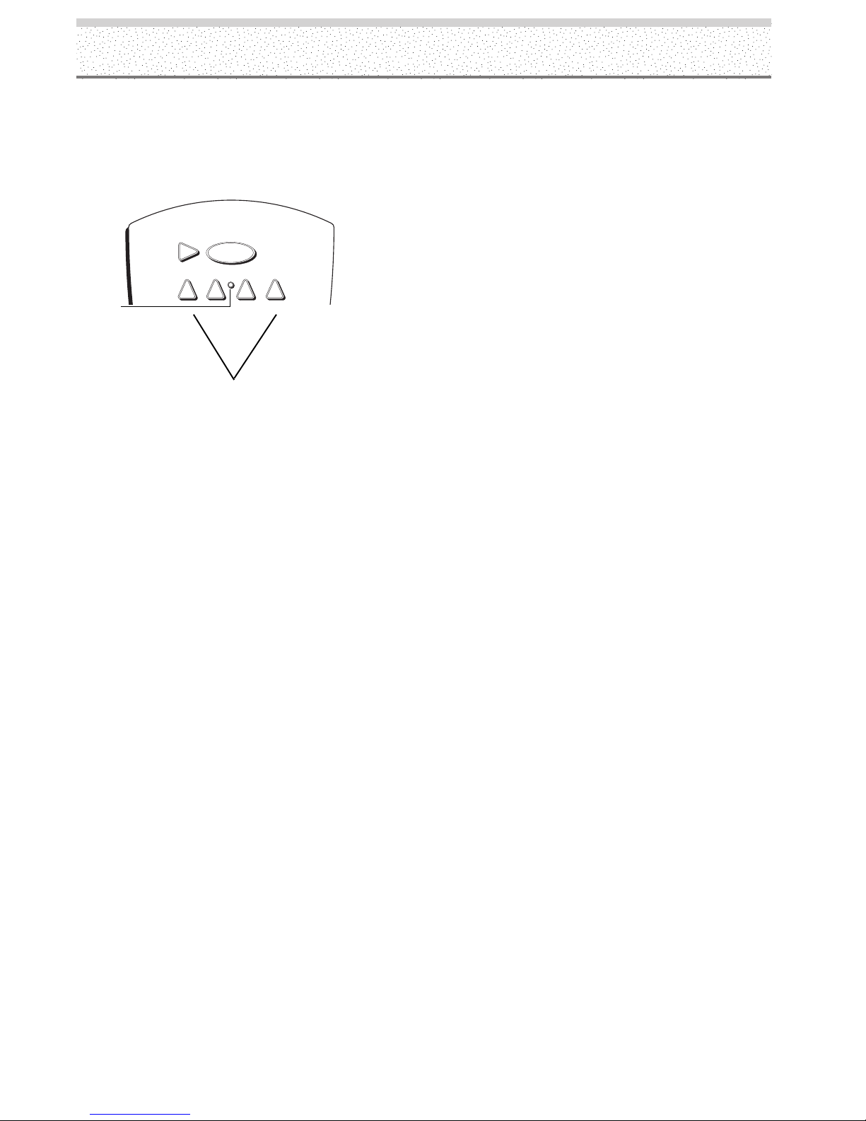
Remote Control
Component Buttons
These are the buttons you program to operate another
component.
Important: The remote may not be compatible with all
models of all brands of components. It may also not
operate all functions of the remote that came with your
component.
3. Press PLAY (the light on the remote starts flashing).
The remote is searching the first set of component codes
(there are several sets of codes). If the component you
want to operate doesn’t turn off automatically after 5
seconds, press PLAY again (the light starts flashing again
as the remote searches through the next set of codes).
Continue pressing PLAY until the component turns off.
NOTE: If the component doesn’t turn off after you’ve pressed the PLAY button 20
times, the component can’t be programmed.
4. Press REVERSE and wait 2 seconds. Repeat this step
until the component turns back on.
5. When the component turns on, press and hold the STOP
button until the light on the remote turns off.
11
Page 16
Remote Control
VCR
DVD
Light
MUTE
AUTO SET
GUIDE
MENU
1
Using Direct Entry
1. Turn on the component you want the remote to operate.
ON•OFF
1
VCR
MONITOR
SAT•CABLE
AUX
2
2. Look up the brand and code number(s) for the component on the
code list on the following pages.
3. Press and hold the component button that corresponds to the
CINEMA
component you want the remote to operate (VCR, RCA DVD, etc.).
(The light on the remote comes on.)
H
+
C
L
O
V
A
V
O
L
C
–
H
GO BACK
INFO
4. Enter the code from the code list. When you begin entering
numbers, the light on the remote turns off. When the last number is
entered, the light turns back on. If the incorrect code is entered, the
light will flash.
5. Release the component button. The light on the remote turns off.
6. Press ON•OFF to see if the component responds to the remote
OK
commands. If it doesn’t, try pressing the component button and
then ON•OFF again.
Z
O
O
M
CLEAR
3
2
7. If you get no response, repeat these steps using the next code listed
for your brand, until the component responds to the remote
commands.
4
5
7
8
INPUT
0
RECORD
AUDIO
REPEAT
u n i v e r s a l
6
9
ANTENNA
PLAY FORWARDREVERSE
STOP PAUSE
ANGLE OPEN
DVD
How To Use the Remote Control After You’ve
Programmed It
Once the remote control has been programmed successfully, you’re
ready to use it to operate other components.
1. Press and release INPUT until the desired input is displayed.
2. Press the component button (MONITOR, VCR, DVD, AUX, or
SAT•CABLE) to operate the component.
3. Press ON•OFF to turn the component on or off.
NOTE: If you keep pressing buttons and nothing happens, you may
have the wrong video source or wrong component selected. You
must select the correct video source and the component button that
matches the component you want to operate.
12
Page 17

Programmable Codes for the Remote Control
VCR (VCR1, VCR2 or AUX
button)
Remote Control
Admiral ......................................... 2132
Adventura ..................................... 2026
Aiko .............................................. 2027
Aiwa ............................................. 2026
Akai ............... 2003, 2004, 2005, 2007,
....................... 2008, 2111, 2112, 2113
American High ............................. 2021
Asha ............................................. 2013
Audio Dynamics ................. 2009, 2010
Audiovox ...................................... 2014
Beaumark ..................................... 2013
Bell & Howell ............................... 2011
Broksonic ........................... 2012, 2025
Calix ............................................. 2014
Candle ........... 2013, 2014, 2015, 2016,
................................. 2017, 2018, 2019
Canon ....................... 2021, 2022, 2114
Capehart ............................. 2020, 2110
Carver ........................................... 2062
CCE .................................... 2027, 2061
Citizen ..................... 2013, 2014, 2015,
............. 2016, 2017, 2018, 2019, 2027
Colortyme .................................... 2009
Colt ............................................... 2061
Craig ............... 2013, 2014, 2023, 2061
Curtis Mathes ................... 2000, 2009,
...................... 2013, 2016, 2018, 2021,
....................... 2022, 2024, 2115, 2131
Cybernex ...................................... 2013
Daewoo ................... 2015, 2017, 2019,
............. 2025, 2026, 2027, 2028, 2110
Daytron ........................................ 2110
DBX .................................... 2009, 2010
Dimensia ............................ 2000, 2131
Dynatech ...................................... 2026
Electrohome ....................... 2014, 2029
Electrophonic ............................... 2014
Emerson .................. 2012, 2014, 2015,
............ 2021, 2024, 2025, 2026, 2029,
............ 2030, 2031, 2032, 2033, 2034,
............ 2035, 2036, 2037, 2038, 2039,
............ 2040, 2041, 2042, 2044, 2045,
............ 2046, 2047, 2065, 2113, 2116,
........................................... 2117, 2130
Fisher ............ 2011, 2023, 2048, 2049,
....................... 2050, 2051, 2052, 2118
Fuji ..................................... 2021, 2119
Funai ............................................ 2026
Garrard ......................................... 2026
GE ............. 2000 (VCR1), 2001 (VCR2),
...................... 2013, 2021, 2022, 2053,
................................. 2115, 2120, 2131
Goldstar .......... 2009, 2014, 2018, 2054
Gradiente ..................................... 2026
Harley Davidson ........................... 2026
Harman Kardon ............................ 2009
Harwood ...................................... 2061
Headquarter ................................. 2011
Hi-Q .............................................. 2023
Hitachi ........... 2055, 2056, 2057, 2107,
................................. 2111, 2120, 2122
Instant Replay .............................. 2021
JCPenney ...... 2009, 2010, 2011, 2013,
............ 2014, 2021, 2022, 2055, 2056,
............. 2058, 2059, 2060, 2107, 2118
JCL ............................................... 2021
Jensen ..................... 2055, 2056, 2111
JVC ................ 2009, 2010, 2011, 2018,
........................................... 2111, 2123
Kenwood ................. 2009, 2010, 2011,
....................... 2016, 2018, 2111, 2123
KLH .............................................. 2061
Kodak ................................. 2014, 2021
Lloyd ............................................ 2026
Logik ............................................ 2061
LXI ................................................ 2014
Magnavox ..... 2021, 2022, 2062, 2063,
....................... 2104, 2105, 2108, 2124
Magnin ......................................... 2013
Marantz ......... 2009, 2010, 2011, 2016,
....................... 2018, 2021, 2062, 2064
Marta ............................................ 2014
Masushita .................................... 2021
MEI .............................................. 2021
Memorex ...... 2011, 2013, 2014, 2021,
....................... 2023, 2026, 2104, 2132
MGA ......................... 2029, 2065, 2113
MGN Technology ......................... 2013
Midland ........................................ 2053
Minolta ..................... 2055, 2056, 2107
Mitsubishi ..... 2029, 2055, 2056, 2065,
...................... 2066, 2067, 2068, 2069,
...................... 2070, 2071, 2072, 2073,
....................... 2074, 2106, 2113, 2123
Montgomery Ward ............. 2075, 2132
Motorola ............................. 2021, 2132
MTC ................................... 2013, 2126
Multitech ................. 2013, 2016, 2026,
........................................... 2053, 2061
NEC ............... 2009, 2010, 2011, 2016,
...................... 2018, 2064, 2076, 2078,
................................. 2079, 2111, 2123
Nikko ............................................ 2014
Noblex .......................................... 2013
Olympus ....................................... 2021
Optimus ............................. 2014, 2132
Optonica ....................................... 2096
Panasonic ...... 2021, 2022, 2109, 2125,
........................................... 2126, 2127
Pentax ..................... 2016, 2055, 2056,
........................................... 2107, 2120
Pentex Research .......................... 2018
Philco ................................ 2021, 2022,
........................................... 2062, 2063
Philips ............. 2021, 2062, 2096, 2124
Pilot .............................................. 2014
Pioneer .................... 2010, 2055, 2080,
........................................... 2081, 2123
Portland .......... 2016, 2017, 2019, 2110
Proscan ..... 2000 (VCR1), 2001 (VCR2),
..................................................... 2131
Protec ........................................... 2061
Pulsar ........................................... 2104
Quarter ......................................... 2011
Quartz .......................................... 2011
Quasar ...................... 2021, 2022, 2125
Radio Shack/Realistic ........ 2011, 2013,
................................ 2014, 2021, 2022,
................................ 2023, 2026, 2029,
................................ 2049, 2050, 2096,
..................................................... 2132
Radix ............................................ 2014
Randex ......................................... 2014
RCA ........... 2000 (VCR1), 2001 (VCR2),
...................... 2003, 2013, 2021, 2055,
...................... 2056, 2082, 2083, 2084,
...................... 2085, 2086, 2087, 2088,
...................... 2089, 2090, 2091, 2107,
.............................................................
2115, 2120, 2125,
........................................... 2131, 2133
Ricoh ............................................ 2128
Runco ........................................... 2104
Samsung ................. 2005, 2013, 2015,
................................. 2033, 2053, 2112
Sanky ................................. 2104, 2132
Sansui ............ 2010, 2092, 2111, 2123
Sanyo ....................... 2011, 2013, 2023
Scott .............. 2012, 2015, 2025, 2032,
....................... 2038, 2065, 2093, 2116
Sears ............. 2011, 2014, 2021, 2023,
...................... 2048, 2049, 2050, 2051,
....................... 2055, 2056, 2107, 2118
Sharp ............. 2017, 2029, 2094, 2095,
................................. 2096, 2097, 2132
Shintom .......... 2004, 2056, 2061, 2098
Shogun ......................................... 2013
Signature ...................................... 2132
Singer ....................... 2021, 2061, 2128
Sony ............... 2004, 2098, 2099, 2119
STS ..................................... 2021, 2107
Sylvania ................... 2021, 2022, 2026,
....................... 2062, 2063, 2065, 2124
Symphonic ................................... 2026
Tandy............................................ 2011
Tashiko ......................................... 2014
Tatung .......................................... 2111
Teac.......................... 2026, 2085, 2111
Technics ............................. 2021, 2109
Teknika .................... 2014, 2021, 2026,
........................................... 2100, 2129
TMK ......................... 2013, 2024, 2047
Toshiba .................... 2015, 2049, 2051,
....................... 2055, 2065, 2093, 2116
Totevision ........................... 2013, 2014
Unitech ......................................... 2013
Vector Research ................ 2009, 2010,
........................................... 2015, 2016
Victor ............................................ 2010
Video Concepts ................. 2009, 2010,
................................. 2015, 2016, 2113
Videosonic .................................... 2013
Wards ............ 2013, 2014, 2015, 2021,
...................... 2023, 2026, 2029, 2055,
...................... 2056, 2061, 2096, 2101,
................................ 2102, 2103, 2107,
........................................... 2116, 2132
XR-1000 ................... 2021, 2026, 2061
Yamaha .................... 2009, 2010, 2011,
........................................... 2018, 2111
Zenith ...................... 2004, 2098, 2104,
........................................... 2119, 2128
13
Page 18

Remote Control
Cable Box (AUX or
SAT•CABLE button)
ABC ...... 5002, 5003, 5004, 5006, 5053
Antronix .............................. 5008, 5009
Archer ...................... 5008, 5009, 5010
Cabletenna ................................... 5008
Cableview .................................... 5008
Colour Voice ....................... 5012, 5013
Comtronic .................................... 5014
Contec .......................................... 5016
Eastern ......................................... 5017
GC Electronics ............................. 5009
GE ...................................... 5000, 5001
Gemini ................................ 5018, 5019
General Instrument ...................... 5003
Hamlin ........... 5020, 5021, 5022, 5028,
........................................... 5035, 5045
Hitachi .......................................... 5003
Jerrold ........... 5003, 5018. 5023, 5024,
........................................... 5046, 5053
Magnavox .................................... 5025
Memorex ..................................... 5026
Movie Time .................................. 5027
NEC .............................................. 5005
NSC .............................................. 5027
Oak ..................................... 5016, 5029
Panasonic ........................... 5048, 5052
Philips ............ 5011, 5012, 5013, 5015,
............. 5019, 5025, 5030, 5031, 5032
Pioneer ............................... 5033, 5034
Proscan .............................. 5000, 5001
RCA ................ 5007, 5047, 5049, 5052
Realistic ........................................ 5009
Regal .................................. 5022, 5035
Regency ....................................... 5017
Rembrandt ................................... 5003
Samsung ...................................... 5034
Scientific Atlanta ............... 5006, 5036,
........................................... 5037, 5038
Signal ........................................... 5018
Signature ...................................... 5003
Sprucer ......................................... 5052
Standard Components ....... 5039, 5044
Starcom .............................. 5018, 5053
Stargate ........................................ 5018
Starquest ...................................... 5018
Tocom ................................ 5004, 5023
Tusa.............................................. 5018
TV86 ............................................. 5027
Unika .................................. 5008, 5009
United Cable ................................ 5053
Universal .................. 5008, 5009, 5010
Viewstar ............................. 5025, 5027
Zenith ................................. 5050, 5051
Satellite Receiver
(SAT•CABLE or AUX button)
Alphastar ...................................... 5079
Chapparal ........................... 5056, 5057
Dishnet ......................................... 5078
Drake .................................. 5058, 5059
Echostar ....................................... 5089
GE ................ 5000 (SAT1), 5001 (SAT2)
General Instruments ......... 5060, 5061,
..................................................... 5062
Hitachi ................................ 5083, 5084
Hughes Network ................ 5077, 5090
JVC ............................................... 5082
Panasonic ..................................... 5075
Philips ........................................... 5085
Primestar ...................................... 5076
Proscan ........ 5000 (SAT1), 5001 (SAT2)
RCA .............5000 (SAT1), 5001 (SAT2),
................................. 5071, 5080, 5081
Realistic ........................................ 5063
Sony ............................................. 5072
STS1 ............................................. 5064
STS2 ............................................. 5065
STS3 ............................................. 5066
STS4 ............................................. 5067
Toshiba ............................... 5068, 5073
Uniden ................................ 5069, 5086
DVD (DVD or AUX button)
Aiwa ............................................. 3009
Apex ................................... 3023, 3057
Daewoo ........................................ 3024
Emerson ............................. 3025, 3026
Funai ............................................ 3026
GE ........................... 3000, 3001, 3027,
................................. 3036, 3038, 3049
.................................... (Portable), 3055
Go Video ...................................... 3054
Hitachi ................................ 3008, 3058
JVC ................. 3002, 3010, 3031, 3051
Kenwood ...................................... 3059
Konka ................................. 3011, 3012
Magnavox .......................... 3003, 3028
Memorex ..................................... 3029
Mintek .......................................... 3030
Mitsubishi 3004 ...................................
NAD ............................................. 3025
Onkyo ........................................... 3032
Oritron .......................................... 3037
Panasonic ........................... 3013, 3033
Philips ............. 3003, 3019, 3021, 3022
Pioneer ..................... 3005, 3034, 3035
Proscan ................... 3000, 3001, 3027,
................................. 3036, 3038, 3049
.................................... (Portable), 3055
Qwestar ....................................... 3037
RCA ......................... 3000, 3001, 3027,
................................. 3036, 3038, 3049
.................................... (Portable), 3055
Samsung ........ 3056, 3060, 3061, 3062
Sansui .......................................... 3044
Sanyo ................................. 3014, 3052
Sharp ........................ 3039, 3041, 3050
Sony ........................ 3006, 3015, 3016,
................................. 3040, 3042, 3043
Sylvania ........................................ 3026
Toshiba .............................. 3007, 3017,
....................... 3020, 3045, 3046, 3047
Zenith ....................... 3018, 3048, 3053
DVD/VCR Combo
(DVD or AUX button or DVD;
VCR1, VCR2, or AUX for VCR)
Go Video ........ (DVD) 3054, (VCR) 2134
JVC ................. (DVD) 3051, (VCR) 2135
RCA ................. (DVD) 3055, (VCR)2136
Samsung ........ (DVD) 3056, (VCR) 2137
Sanyo ............. (DVD) 3052, (VCR) 2138
Zenith ............. (DVD) 3053, (VCR) 2139
LaserDisc
(VCR1, VCR2, and AUX button)
RCA .............................................. 2133
Audio (AUX button only)
RCA and Dimensia
AM/FM ..................................... 4003
Aux ........................................... 4004
Phono ....................................... 4005
CD ............................................ 4007
Tape ......................................... 4006
Receivers
Aiwa .......... 4261, 4262, 4263, 4264,
................... 4265, 4266, 4267, 4277
Denon ...................................... 4283
Harman Kardon ........................ 4276
JBL ........................................... 4276
JVC .......................................... 4268
Kenwood .................................. 4269
Onkyo ...................................... 4278
Optimus ................................... 4284
Panasonic ....................... 4279, 4280
Pioneer ..................................... 4275
RCA .......................................... 4270
Sherwood ................................ 4282
Sony ...................... 4271, 4272,4281
Technics ......................... 4279, 4380
Wards ....................................... 4275
Yamaha ................ 4273, 4274, 4275
14
Page 19

Installation and Connections
Installation of the Unit
Installation using a stand or wall mount bracket
• Please be sure to request installation or mounting of this unit
or the installation bracket by the dealer where purchased.
• When installing, be sure to use the bolts provided with the
stand or installation bracket.
• For details concerning installation, please refer to the
instruction manual provided with the stand or installation
bracket.
Installation using accessories other than the
stand or installation bracket (sold separately)
• When possible, please install using parts and accessories
manufactured by Thomson. Thomson will not be held
responsible for accident or damage caused by the use of parts
and accessories manufactured by other companies.
• For custom installation, please consult the dealer where the
unit was purchased.
Note for U.S. customers:
If you prefer, we can provide you with the name of an Authorized
Service Representative who will visit your home for a fee to
install your electronic entertainment system and to instruct you
in its operation. For details about this service, call
1-888-206-3359.
For additional assistance while using your RCA Scenium product,
please visit www.rcascenium.com/customersupport.
Wall-mount installation of the unit
This unit has been designed with bolt holes for
wall-mount installation, etc.. The installation holes that
can be used are shown in the diagram below.
• Be sure to attach in 4 or more locations above and
below, left and right of the center line.
• Use bolts that are long enough to be inserted 1/2 inch
(12 mm) to 11/16 inch (18 mm) into the main unit from
the attaching surface for both a holes and b holes.
Refer to the side view diagram below.
• As this unit is constructed with glass, be sure to install
it on a flat, unwarped surface.
CAUTION
To avoid malfunction, overheating of this unit, and possible fire
hazard, make sure that the vents on the main unit are not
blocked when installing. Also, as hot air is expelled from the air
vents, be careful of deterioration and dirt build up on rear surface
wall, etc.
CAUTION
Please be sure to use an M8 (Pitch = 1.25 mm) bolt. (Only this
size bolt can be used.)
b hole
Air vents (fan)
Attaching surface
Installation
bracket, etc..
a hole
Bolt
1/2 inches (12 mm) to
11/16 inches (18 mm)
Bolt
a hole
Center line
Rear view diagram
a hole
Main unit
Center line
b hole
b hole
1/2 inch (12 mm) to
11/16 inch (18 mm)
Side view diagram
CAUTION
This monitor unit weighs approximately 90 lbs (41 kg) and has little front-to-back depth, making it very unstable when stood
on edge. As a result, two or more persons should cooperate when unpacking, moving, or installing the monitor.
CAUTION
This unit incorporates a thin design. To ensure safety if vibrated or shaken, please be sure to take measures to prevent the
unit from tipping over.
15
Page 20

Installation and Connections
About the Input Connectors
on this Unit
Consult the following chart when making connections to
your plasma monitor (pages 16-20).
Connected
component and signals
AV
Personal
computer
*1 Although INPUT1/INPUT2 are compatible with various kinds of
signals, setup using the on-screen menu is necessary after
connections are made in order match the characteristics of the
source component (pages 25-26).
*2 INPUT1 is compatible with Microsoft’s Plug & Play (VESA DDC
1/2B).
*3 Depending on the video output board of the computer, this type
of connection may not be possible.
*4 VESA DDC 2B only.
Input Connector
DVI
Analog RGB
Component video
component
S video
Composite video
Analog RGB
S video
(PC)
Composite video
INPUT
*1
1
INPUT
*2
INPUT
*1
2
INPUT
3
4
*3
*3
INPUT
5
Connection to AV components
Connection to AV component that has
component video jacks
Make component video connections for AV components
such as DVD and LD players or similar components with
component video output capability.
*4
For audio connections, see page 22.
When connecting to INPUT1
INPUT1
ANALOG RGB (ANALOG RGB)
OUTPUT
Connection to INPUT1 and
INPUT2
Various components can be connected to the INPUT1 and
INPUT2 terminals. After connections are made, on-screen setup
is necessary to match the characteristics of the connected
component. Please see pages 25-26 for on-screen setup after
connection.
INPUT2 terminal
Output source
Video component/
Personal
computer (PC)
with RGB output
Video component
with component
video output
: Do not connect anything. : Connect to this jack.
Note
Components compatible with INPUT1 are also compatible with INPUT2.
When making connections to INPUT1, please refer to supplement 4 on
page 47.
[ON SYNC]
GBR
G with SYNC
GBR
YCB/PB CR/PR
B
B
R
RG
[H/V SYNC]
HD VD
H/V SYNC
HD
VD
On-screen setup is necessary after connection. Please
see pages 25-26.
When connecting to INPUT2
(ON SYNC) (H/V SYNC)
GBRHD VD
INPUT2
75 2.2
Ô
Ω kΩ
Use the supplied BNC to RCA phono
jack adapters, if necessary.
Connect the Y signal to the G terminal, the CB/PB signal to
the B terminal, and the C
R/PR signal to the R terminal.
On-screen setup is necessary after connection. Please
see pages 25-26.
For the screen sizes and input signals that INPUT1 and
INPUT2 are compatible with, please refer to
supplement 1 (page 45) and supplement 2 (page 46).
16
Page 21

Installation and Connections
Connection to AV components
(continued)
Connection of G with SYNC analog RGB source
Make G with SYNC connections for a component with
output that has the synchronization signal combined with
the green signal.
When connecting to INPUT1
INPUT1
ANALOG RGB (ANALOG RGB)
On screen setup is necessary after connection.
Please see pages 25-26.
OUTPUT
Connection of composite SYNC analog RGB
source
Make composite SYNC connections for a component
with output that has the vertical synchronization signal
combined with the horizontal synchronization signal.
When connecting to INPUT1
INPUT1
ANALOG RGB (ANALOG RGB)
On-screen setup is necessary after connection.
Please see pages 25-26.
When connecting to INPUT2
OUTPUT
When connecting to INPUT2
(ON SYNC) (H/V SYNC)
GBRHD VD
INPUT2
75 2.2
Ô
Ω kΩ
Use the supplied BNC to RCA phono
jack adapters, if necessary.
On screen setup is necessary after connection.
Please see pages 25-26.
Note
When making G with SYNC connections, do not make any
connections to the VD or HD terminals. If connections are made,
the picture may be not displayed normally.
(ON SYNC) (H/V SYNC)
GBRHDVD
INPUT2
75 2.2
Ô
Ω kΩ
Use the supplied BNC to RCA phono
jack adapters, if necessary.
When using INPUT2, set the impedance selector switch
to match the output impedance of the connected
component’s synchronization signal.
When the output impedance of the component’s
synchronization signal is 75 Ω, set this switch to the 75 Ω
position.
On-screen setup is necessary after connection.
Please see pages 25-26.
Note
When making composite SYNC connections, do not connect
anything to the VD terminal. If connected to, the picture may not
be displayed properly.
17
Page 22

Installation and Connections
Connection to a personal
computer
Connection method differs depending on the computer
type. When connecting, please thoroughly read the
computer’s instruction manual.
Before making connections, be sure to make sure that
the personal computer’s power and this unit’s main
power is off.
For the PC input signals and screen sizes that this unit is
compatible with, please refer to supplement 1 (page 45).
For audio connections, see page 22.
Connection of separate SYNC analog RGB
source
Make separate SYNC connections for a personal
computer that has RGB output separated into 5 output
signals: green, blue, red, horizontal synchronization signal,
and vertical synchronization signal.
When connecting to INPUT2
(ON SYNC) (H/V SYNC)
GBRHDVD
INPUT2
75 2.2
Ô
Ω kΩ
When connecting to INPUT1
INPUT1
ANALOG RGB (ANALOG RGB)
OUTPUT
Connect the cable corresponding to the shape of the
input terminal on this unit and the personal computer’s
output terminal.
Secure by tightening the terminal screws on both units.
After connecting, on-screen setup is necessary.
Please see pages 25-26.
Note
Depending on the type of computer model being connected, a
conversion connector or adapter etc. provided with the computer
or sold separately may be necessary.
For details, please read your PC’s instruction manual or consult
the maker or nearest dealer of your computer.
Use the supplied BNC to
RCA jackphono adapters,
if necessary.
When using INPUT2, set the impedance selector switch
to match the output impedance of the connected
computer’s synchronization signal.
When the output impedance of the computer’s
synchronization signal is 75 Ω, set this switch to the 75 Ω
position.
On-screen setup is necessary after connection.
Please see pages 25-26.
When connecting to OUTPUT (INPUT1)
INPUT1
ANALOG RGB (ANALOG RGB)
OUTPUT
To an external monitor
With this unit, it is possible to output the video signal to
an external monitor or other component from the
OUTPUT (INPUT1) terminal.
Note
A video signal will not be output from the OUTPUT (INPUT1)
terminal when the main power of this unit is off or in standby.
18
Page 23

Installation and Connections
Connection to a personal
computer
(continued)
Connection of G with SYNC analog RGB source
Make G with SYNC connections for a personal computer
with output that has the synchronization signal combined
with the green signal.
When connecting to INPUT1
INPUT1
ANALOG RGB (ANALOG RGB)
OUTPUT
Connection of composite SYNC analog RGB
source
Make composite SYNC connections for a personal
computer with output that has the vertical
synchronization signal combined with the horizontal
synchronization signal.
When connecting to INPUT1
INPUT1
ANALOG RGB (ANALOG RGB)
On-screen setup is necessary after connection.
Please see pages 25-26.
OUTPUT
On screen setup is necessary after connection.
Please see pages 25-26.
When connecting to INPUT2
(ON SYNC) (H/V SYNC)
GBRHD VD
INPUT2
75 2.2
Ô
Ω kΩ
Use the supplied BNC to RCA jack
phono adapters, if necessary.
On screen setup is necessary after connection.
Please see pages 25-26.
Note
When making G with SYNC connections, do not make any
connections to the VD or HD terminals. If connections are made,
the picture may be not displayed normally.
When connecting to INPUT2
(ON SYNC) (H/V SYNC)
GBRHDVD
Use the supplied BNC to RCA jack
INPUT2
75 2.2
Ô
Ω kΩ
phono adapters, if necessary.
When using INPUT2, set the impedance selector switch
to match the output impedance of the connected
computer’s synchronization signal.
When the output impedance of the computer’s
synchronization signal is 75 Ω, set this switch to the 75 Ω
position.
On-screen setup is necessary after connection.
Please see pages 25-26.
Notes
• When making composite SYNC connections, do not connect
anything to the VD terminal. If connected, the picture may not
be displayed properly.
• On some types of Macintosh® components, G with SYNC and
composite SYNC are both output. With this type of
component, please connect using the G ON SYNC connection.
19
Page 24

Installation and Connections
Connection to INPUT3
Connect an AV component that has S-video output
terminal to the S-VIDEO input terminal.
INPUT3
AUDIO
R
S-VIDEO
L
AV component
Connection to INPUT4
Connect an AV component that has a video output
terminal to the INPUT4 terminal.
INPUT4
AUDIO
R
VIDEO
L
AV component
Connection to INPUT5
Connect an AV component that has a DVI video output
terminal to the INPUT5 DVI terminal.
AUDIO
INPUT5
DVI VIDEO
R
L
AV component
20
Page 25

Installation and Connections
About HDTV Set Top Box Connection
To ensure proper connection, please carefully read the instruction manual supplied with the HDTV set top box.
The set top box output signals that this monitor is compatible with are as follows.
Video
signal type
HDTV
SDTV
Video signal
1080i
720p
480i
480p
Video
signal format
Component
RGB
Digital
Composite
S Video
Component
RGB
Component
RGB
Digital
Terminals where connection is possible
INPUT1
INPUT4INPUT3INPUT2
INPUT5
21
Page 26

Installation and Connections
Audio Connections
Before making connections, be sure to check that the
audio component’s power and the unit’s main power is
off.
Connecting the speakers
This unit is equipped with a 5W+5W internal amplifier. If
speakers are to be connected to the unit, following the
accompanying connection instructions.
10 mm
Note
When making speaker connections, be sure to match the
polarities (+ and –) of the speaker terminals on this unit and the
corresponding terminals on the speakers. If the polarity is
reversed, the sound will be unnatural and lack bass.
Twist exposed
wire strands
together.
Push tab to the open
position, and insert the
wire. Then, close tab
firmly to secure the wire
in place.
Audio connections for component (computer)
connected to INPUT 1 or INPUT 2
75 2.2
Ô
Ω kΩ
AUDIO
INPUT
(INPUT1/2)
OUTPUT
VD
Use the supplied stereo mini to RCA
plugs cable.
Audio input to the AUDIO INPUT terminal (stereo mini
jack) is possible for a component connected to either
INPUT1 or INPUT2.
Sound is output from both the AUDIO OUTPUT terminal
(stereo mini jack) and the SPEAKER terminals according
to the video input selection.
Making connections to the audio inputs on this
unit
This unit features four audio inputs and one audio output.
The following chart shows the video inputs and the
corresponding audio input terminals.
Video
input
INPUT1
INPUT2
INPUT3
INPUT4
INPUT 5
Audio input
terminal
Stereo mini jack
(L/R)
RCA jacks (L/R)
RCA jacks (L/R)
RCA jacks (L/R)
Sound output
Sound of the selected video
input is output from the
• SPEAKER terminals
• Stereo mini jack (L/R).
Audio connection for component connected to
INPUT3
INPUT3
AUDIO
R
S-VIDEO
L
Audio input to the AUDIO INPUT3 terminals (pin jacks (L/
R)) is possible for a component connected to INPUT3.
Sound is output from both the AUDIO OUTPUT terminal
(stereo mini jack (L/R)) and the SPEAKER terminals
according to the video input selection.
22
Page 27

Audio connection for component connected to
INPUT4
INPUT4
AUDIO
R
VIDEO
L
Audio input to the AUDIO INPUT4 terminals (pin jacks (L/
R)) is possible for a component connected to INPUT4.
Sound is output from both the AUDIO OUTPUT terminal
(stereo mini jack (L/R)) and the SPEAKER terminals
according to the video input selection.
Installation and Connections
Audio connection for component connected to
INPUT5
DVI VIDEO
R
L
AUDIO
INPUT5
Audio input to the AUDIO INPUT5 terminals (RCA jacks
(L/R)) is possible for a component connected to INPUT5.
Sound is output from both the AUDIO OUTPUT terminal
(stereo mini jack (L/R)) and the SPEAKER terminals
according to the video input selection.
23
Page 28

Installation and Connections
Power Cord Connection
Connect the power cord after all component connections
have been completed.
1
2
1 Connect the power cord to this unit.
2 Plug the power cord into a power outlet.
CAUTION
÷ Use only the power cord provided.
÷ Do not use a power supply voltage other than that indicated
(AC 120 V, 60 Hz) as this may cause fire or electric shock.
÷ For the plasma monitor, a three-wire power cord with a ground
terminal is used for efficiency protection. Always be sure to
connect the power cord to a three-pronged grounded outlet
and make sure that the cord is properly grounded. If you use a
power source converter plug, use an outlet with a ground
terminal and screw down the ground line.
24
Page 29

Setting Up the System
Setup after Connection
After components have been connected to INPUT1 or
INPUT2, on-screen setup is necessary.
Follow the procedure described below and make settings
as they apply to the type of components connected.
Setting the Screen Mode/Input
Signal Format
Notes
• The Screen Mode setting (steps 6 – 7) is required only when
using the following input signal refresh rates: 1 31.5 kHz
horizontal / 60 Hz vertical; 2 48.4 kHz horizontal / 60 Hz
vertical; 3 56.5 kHz horizontal / 70 Hz vertical. No setup is
necessary for signals with other refresh rates, since
adjustments are performed automatically (the SETTING item
will not be displayed).
• The Input Signal Format setting (steps 8 – 9) is required only
when using a video signal. It is not supported when using a
computer signal, or when the Screen Mode setting has been
used to select a mode other than VIDEO.
1 Switch the main power switch on the connection
panel to the on position to turn on the unit’s main
power.
The STANDBY/ON indicator lights red.
5 Press / to select SET UP.
MAIN MENU INPUT1
PICTURE
SET UP
COLOR T MEP
DIGITAL NR
HIGH CO TNRA TS
FILM MODE
CLAM
SETT I N
V
IDEO
SELECT CHANGE EXIT
[When using a computer signal]
MAIN MENU INPUT1
PICTURE
SCREEN
AUTO POWER
CLAMP
SETT I N
PSITIONO
G
SIGNAL
OK
PSITIONO
G
OF FAUTOPPOWER
O
OPTION
:
O
FF
:
M
IDDLE
:
L
OW
:
O
FF
:
O
FF
:
A
UTO
:
V
IDEO
:
R
GB
CLEAR
SET UP OPTION
:
O
FF
FF
:
A
UTO
:
V
GA
6 Press / to select SETTING, then press OK.
MAIN MENU INPUT1
PICTURE
SET UP
COLOR T MEP
DIGITAL NR
HIGH CO TNRATS
FILM MODE
CLAM
SETT I N
V
IDEO
PSITIONO
G
SIGNAL
OPTION
OF FAUTOPPOWER
:
O
:
M
:
L
:
O
:
O
:
A
:
V
:
R
FF
IDDLE
OW
FF
FF
UTO
IDEO
GB
2 Press POWER to put the unit in the operation
mode.
The STANDBY/ON indicator turns green.
3 Select INPUT1 or INPUT2.
4 Press MENU to display the menu screen.
The menu screen appears.
MAIN MENU INPUT1
0
0
0
0
0
OK
0
0
+
6
0
+
60
+
60
0
0
OPTION
CLEAR
SET UP OPTION
PICTURE
CONT RAST
BRIGHTNESS
CO LOR
TINT
SHARPNESS
RSETE
SET UP
:
:
:
:
:
SELECT ENTER EXIT
[When using a computer signal]
MAIN MENU INPUT1
PICTURE
CONT RAST
BR
IGHTNESS
RLEVEL
.
GLEVEL.
BLEVEL.
HENHANCE.
VENHAN CE.
RSETE
SCREEN
:
:
:
:
:
:
:
SELECT CHANGE EXIT
OK
CLEAR
[When using a computer signal]
MAIN MENU INPUT1
PICTURE
POWER
CLAMP
SETT I N
SCREEN
MNAGEMEA
PSITIONO
G
SET UP OPTION
:
N
O
T
FF
:
A
UTO
:
V
GA
7 Press / to select the display mode.
When a component other than a personal computer is
connected, set to “VIDEO”.
:
SETT I NG
SELEC
T
1 When the input signal has a refresh rate of 31.5 kHz
(horizontal) and 60 Hz (vertical), pressing
cause the display mode to change alternately as
follows:
2 When the input signal has a refresh rate of 48.4 kHz
(horizontal) and 60 Hz (vertical), pressing
cause the display mode to change alternately as
follows:
VIDE
O
K
VIDEO
O
SE
T
VGA
XGA
W-XGA
CLEAR
W-VGA
EXI
T
/ will
/ will
25
Page 30

Setting Up the System
3 When the input signal has a refresh rate of 56.5 kHz
(horizontal) and 70 Hz (vertical), pressing
/ will
cause the display mode to change alternately as
follows:
XGA
W-XGA
8 When using a video signal (When VIDEO is selected),
press
/ to select VIDEO SIGNAL.
MAIN MENU INPUT1
PICTURE
SET UP
COLOR T MEP
DIGITAL NR
HIGH CO TNRA TS
FILM MODE
CLAM
SETT I N
V
IDEO
SELECT CHANGE EXIT
PSITIONO
G
SIGNAL
OK
OPTION
OF FAUTOPPOWER
:
O
:
M
:
L
:
O
:
O
:
A
:
V
:
R
FF
IDDLE
OW
FF
FF
UTO
IDEO
GB
CLEAR
9 Press OK repeatedly to select the input signal
format.
Selection will change as follows each time OK is
pressed.
RGB
COMPONENT
The table below shows what settings are appropriate
and available for the type of connections made.
Set SETTING and VIDEO SIGNAL as follows.
SET UP
Connected
component
Component video output
of a DVD player, etc.
RGB video output of a
video deck etc., with RGB
output
RGB video output of a PC
SETTING
VIDEO
VIDEO
VGA
W-VGA
XGA
W-XGA
VIDEO SIGNAL
COMPONENT
RGB
10 When the setup is completed, press CLEAR to exit
the menu screen.
Note
Make this setup for each input (INPUT1 and INPUT2).
CLAMP POSITION setup
Depending on the signal, analog RGB signals may result
in the screen image appearing with a whitish or greenish
cast. In such cases, set “CLAMP POSITION” to LOCKED.
• Normally, leave this setting at AUTO.
Setup of CLAMP POSITION
1 Press MENU to display the menu screen.
The menu screen appears.
MAIN MENU INPUT1
PICTURE
CONT RAST
BR
IGHTNESS
RLEVEL
.
GLEVEL.
BLEVEL.
HENHANCE.
VENHAN CE.
RSETE
SCREEN
:
:
:
:
:
:
:
SELECT ENTER EXIT
2 Press / to select SET UP.
MAIN MENU INPUT1
PICTURE
SCREEN
AUTO POWER
CLAMP
SETT I N
3 Press / to select CLAMP POSITION.
MAIN MENU INPUT1
PICTURE
POWER
CL AMP
SETT I N
SCREEN
MNAGEMEA
PSITIONO
G
4 Press OK to select LOCKED.
MAIN MENU INPUT1
PICTURE
POWER
CL AMP
SETT I N
SCREEN
MNAGEMEA
PSITIONO
G
Mode selection will change as follows each time OK
is pressed.
3 AUTO
LOCKED 2
5 When the setup is completed, press CLEAR to exit
the menu screen.
Notes
• Make this CLAMP POSITION setting for each applicable input
(INPUT1 and INPUT2).
• When using this setup, be sure to carefully check the signal
output of the component that you are using. For details, please
refer to the instruction manual supplied with the component
you are connecting.
0
0
+
6
0
+
60
+
60
0
0
OK
O
PSITIONO
G
SET UP OPTION
SET UP OPTION
SET UP OPTION
CLEAR
SET UP OPTION
:
O
FF
FF
:
A
UTO
:
V
GA
:
N
O
T
FF
:
A
UTO
:
V
GA
:
N
O
T
FF
:
L
OCKED
:
V
GA
26
Page 31

Selecting an Input Source
:
085
512 684
k
HzfV .
:
1717
HzfH .
POUSUPNSREDTINALG
CAU I O NT
FULL
INPUT
1
X
This section explains the basic operation of this unit.
Outlined on the following pages is how to turn the main
power on and off, put this unit in the operation or standby
mode and how to select connected components.
Before you begin, make sure you have:
• Made connections between this unit and AV components
or personal computer as described in the section
“Installation and Connections” starting on page 8.
• Set up the on-screen menu to input signals from
components connected to INPUT1 and INPUT2 as
described in the section “Setting Up the System” on
page 25.
If no connections are made to these terminals,
on-screen setup is not necessary.
ON•OFF
VCR
1
MONITOR
SAT•CABLE
AUX
VCR
2
DVD
MUTE
CINEMA
H
+
C
V
L
O
O
L
V
C
–
H
A
AUTO SET
1
4
7
REPEAT
POWER
INPUT
Main Unit Operating Panel
CINEMA
– VOLUME +
Remote Control
1 Switch the main power switch on the main unit to
the on position to turn the main power on.
The STANDBY/ON indicator lights red.
2 Press POWER to put this unit in the operation mode.
The STANDBY/ON indicator turns green.
GUIDE
OK
Z
O
MENU
2
5
8
INPUT
0
PLAY FORWARDREVERSE
STOP PAUSE
RECORD
AUDIO
DVD
u n i v e r s a l
O
M
ANGLE OPEN
GO BACK
3
6
9
ANTENNA
INFO
CLEAR
Operations
3 Press INPUT on the remote control unit or the
main unit to select the input.
Input changes each time the main unit’s INPUT is
pressed as follows.
3 INPUT1
• When the menu screen is displayed, changing the
signal input will cause the menu screen to turn off.
• If the input computer signal is not supported by the
monitor, the following message will be displayed:
4 Use the VOL buttons on the remote control or the
VOLUME –/ + buttons on the front of the monitor
to adjust the volume.
If no audio connections are made to this unit, this step
is not necessary.
5 When viewing is finished, press POWER to put the
unit in standby mode.
The STANDBY/ON indicator will blink and then remain
lit (red) indicating that the standby mode is engaged
(no operation will be possible).
6 Use the main power switch on the back of the
monitor to turn the power off.
The STANDBY/ON indicator may continue to light for a
short while even after the main power is turned off.
CAUTION
Please do not leave the same picture displayed on the screen for
a long time. Doing so may cause a phenomenon known as
“screen burn” which leaves a ghost, or residual, image of the
picture on the screen.
3 INPUT2
INPUT5 2
CAU I O NT
TOU NOARFGE
:
:
––––
INPUT4 2
k
7715
HzfH .
HzfV .
020
3INPUT3
INPUT
1
FULL
27
Page 32

Operations
To adjust the volume
Use the VOL buttons on the remote control or
the VOLUME – / + buttons on the front of the
monitor.
Use the VOLUME buttons to adjust the volume of the
connected speakers.
:
VOLUME
5
To mute the sound
Press MUTE on the remote control.
Press MUTE again to restore the sound.
Muting is automatically canceled about 8 minutes after
the button is pressed, and the volume level is adjusted to
the minimum level.
Use the VOL buttons on the remote or the
VOLUME – / + buttons on the front of the monitor to
adjust the volume to the desired level.
To confirm display settings
Press INFO on the remote control unit.
The currently selected input, screen size and refresh rates
will be displayed for about 3 seconds.
INPUT
1
:
k
531
060
X
460 840
HzfH .
HzfV .
ODBYTDOT
:
Note
The displayed refresh rates may be slightly different from the
actual values.
28
Page 33

Operations
Screen Size Selection
This unit incorporates screen modes of various height and
width ratios. For optimal viewing, we recommend that
you select the screen mode that best matches the video
source that you are viewing.
Changing the screen size
The size of the picture or the picture’s range projected on
the screen can be changed between 4 screen sizes
described in the table on this page.
Press CINEMA to select the size.
The screen size changes each time CINEMA is pressed
as follows.
[During video signal input]
3 WIDE 3 4:3
ZOOM 2
[During personal computer signal input]
3 DOT BY DOT 3 4:3
FULL 2
Consult the table Computer Signal Formats Supported
(page 45) for information regarding screen sizes
supported by each signal format.
FULL 2
During video signal input
How the picture looks
WIDE
4:3
FULL
ZOOM
During personal computer signal input
1 DOT BY DOT
The input signal and the screen maintain a dot to line ratio
of 1:1 and is thus highly faithful to the source.
Suitable for when viewing news or
sports programs. Movies or sports
programs can be viewed with an
expansive powerful image.
Suitable for when viewing news or
sitcoms. The video software can be
viewed in its original screen frame
size. (To prevent screen burn on this
monitor, the displayed position of the
screen frame will be slightly different
each time the power is turned on.)
Suitable for squeezed wide screen
images.
Mainly suitable for viewing
Cinemascope, Letterbox, and other
such movie images.
Provides a more expansive, powerful
image.
Notes
• When the WIDE, ZOOM or FULL setting is used to display a
non-wide screen 4:3 picture fully on a wide screen, a portion
of the picture may be cut off or appear deformed.
• Be aware that when the monitor is used for commercial or
public viewing purposes, selecting the WIDE, ZOOM or FULL
mode settings may violate the rights of authors protected
under copyright law.
• When DOT BY DOT or 4:3 screen sizes are selected, the
display position is moved slightly each time the power is
turned on, in order to prevent image burning.
Moving the screen position
upward or downward
When a vista size movie etc., is viewed at the ZOOM
setting, the image may not be centered on the screen,
and may extend past the edge of the screen.
In this case, adjust the screen to a clearly viewable
position using
/ .
Automatic screen size
When a High-Definition Television signal (1080i or 720p) is
detected, the screen size is automatically changed to
FULL.
A
640 dots
1280 dots
2 4:3
The monitor fills the screen
as much as possible without
altering the aspect ratio of
the input signal.
A
480
768
lines
lines
(Illustration shows
640 x 480 input.)
3 FULL
The monitor is presented
with a widescreen aspect
ratio of 16:9 and fills the
entire screen.
A
29
Page 34

Operations
Partial Image Enlargement
(Zoom)
This monitor allows any one of nine screen areas (AREA 1
to AREA 9) to be selected and enlarged to x1.5, x2, x3, or
x4. When performing point zoom enlargement, the
direction buttons (
enlarged portion up-down and right-left.
Notes
• The ZOOM function is supported only when the input signal is
from a computer.
• Whenever ZOOM is selected, the screen size automatically
changes to FULL.
1 Press the remote control’s OK/ZOOM button.
/ / / ) can be used to move the
2 Press / / / as required to select the desired
screen area (AREA 1 to AREA 9).
3 Press OK/ZOOM to select the zoom ratio.
Pressing OK/ZOOM repeatedly changes the zoom
ratio in the following order:
3 x 1.5
x 4.0 2
3 x 2.0
x 3.0 2
• When the zoom ratio is changed, the screen image
is enlarged based on the screen center.
•
/ / / can be used to move the enlarged
portion up-down and right-left.
• If no operation is undertaken for three seconds or
more, the display screen will disappear.
SET or
/ / / can be pressed again if desired
to change the zoom ratio or display position.
4 Press CLEAR to cancel the zoom.
The zoom function will also be canceled whenever the
input signal changes, the menu screen is displayed, or
the input changes.
SELEC
AREA 1 display range
AREA 1
x 4.0
x 2.0
x 1.5
AREA 4 display range
AREA 4
x 4.0
x 2.0
x 1.5
AREA 7 display range
T
CLEAR
O
K
x 3.0
x 3.0
EXI
ZOOM
T
AREA 2 display range
AREA 5 display range
AREA 8 display range
AREA 2
x 4.0
x 2.0
x 1.5
AREA 5
x 4.0
x 2.0
x 1.5
AREA 3 display range
x 3.0
x 3.0
AREA 6 display range
x 3.0
x 3.0
AREA 9 display range
AREA 3
x 4.0
x 2.0
x 1.5
AREA 6
x 4.0
x 2.0
x 1.5
AREA 7
x 4.0
x 2.0
x 1.5
x 3.0
30
AREA 8
x 4.0
x 2.0
x 1.5
x 3.0
x 3.0
AREA 9
x 4.0
x 2.0
x 1.5
Page 35

Operations
Automatic Power OFF
This monitor is equipped with automatic powermanagement and auto-power-off functions, which allow
the unit to automatically switch to power-saving mode
when no sync signal is detected.
(A warning message appears onscreen before these
functions operate.)
Notes
• Power Management settings are supported only when a
computer signal is input to INPUT1 and INPUT2.
• The auto-power-off function can be used only in those cases
other than the inputs used in the preceding item.
• Always turn off the plasma monitor’s main power switch when
not using the monitor for extended periods of time.
1 Press MENU to display the menu screen.
MAIN MENU INPUT1
PICTURE
CONT RAST
BR
IGHTNESS
RLEVEL
.
GLEVEL.
BLEVEL.
HENHANCE.
VENHAN CE.
RSETE
SCREEN
:
:
:
:
:
:
:
SELECT ENTER EXIT
2 Press / to select SET UP.
[When computer signal is input to INPUT 1]
MAIN MENU INPUT1
PICTURE
[In all other cases]
MAIN MENU INPUT2
PICTURE
SCREEN
AUTO POWER
CLAMP
SETT I N
SELECT CHANGE EXIT
SCREEN
AUTO POWER
CLAMP
SETT I N
+
+
+
PSITIONO
G
PSITIONO
G
6
60
60
0
0
0
0
0
OK
O
OK
O
SET UP OPTION
CLEAR
SET UP OPTION
:
O
FF
FF
:
A
UTO
:
V
GA
CLEAR
SET UP OPTION
:
O
FF
FF
:
A
UTO
:
V
GA
3 Press / to select either the POWER
MANAGEMENT or AUTO POWER OFF mode.
[When computer signal is input to INPUT1]
MAIN MENU INPUT1
PICTURE
SCREEN
POWER
MNAGEMEA
CLAMP
PSITIONO
SETT I N
G
SELECT CHANGE EXIT
SET UP OPTION
N
T
OK
:
:
:
O
A
V
FF
UTO
GA
CLEAR
[In all other cases]
MAIN MENU INPUT2
PICTURE
SCREEN
AUTO POWER
CLAMP
SETT I N
SET UP OPTION
O
PSITIONO
G
FF
:
O
FF
:
A
UTO
:
V
GA
4 Press OK to confirm selection of the POWER
MANAGEMENT or AUTO POWER OFF.
• When OFF is selected, the monitor will continue in
operating mode, regardless of the presence/
absence of an input sync signal.
• When POWER MANAGEMENT: ON is selected, if
a sync signal is not detected, a warning message is
displayed for 8 seconds, after which the monitor
automatically enters the power-saving mode (*1)
and the STANDBY/ON indicator flashes green. If a
sync signal (*2) is input again later, the plasma
monitor automatically returns to normal operating
mode.
*1. Power consumption about 1W
*2. Except when input signal is G with SYNC or composite
SYNC
• When AUTO POWER OFF: ON is selected, if no
sync signal is detected for 8 minutes or more, a
warning message will be displayed for 30 seconds,
after which the unit's power will switch to
STANDBY mode.
3 OFF
ON 2
5 When the setup is finished, press CLEAR to exit
the menu screen.
Note
The POWER MANAGEMENT and AUTO POWER OFF functions
must be set individually for each input (INPUT 1–5).
SELECT CHANGE EXIT
OK
CLEAR
To return to operating mode:
• To return to normal operation from POWER
MANAGEMENT mode: either operate the computer,
or press INPUT on the main unit operating panel or
remote control.
• To return to normal operation from AUTO POWER
OFF mode: Press STANDBY/ON on the front of the
monitor or ON•OFF on the remote control.
31
Page 36

Monitor Panel Adjustments
Adjusting the Picture Quality
Note
Make these adjustments for each input (INPUT1 to INPUT5) and
signals.
PICTURE menu adjustment items
Below are brief descriptions of the options that can be set
in the PICTURE menu.
[When video signal is input]
CONTRAST ············· Adjust according to the surrounding
brightness so that the picture can be
seen clearly.
BRIGHTNESS ·········· Adjust so that the dark parts of the
picture can be seen clearly.
COLOR ···················· Adjust to the desired depth. (Setting
to a slightly deeper color will create
a natural looking picture.)
TINT························· Adjust so that flesh tones look
normal.
SHARPNESS ··········· Normally set to the center position.
To create a softer picture, set to the
left of center. To create a sharper
picture, set to the right of center.
[When computer signal is input to INPUT 1 or 2]
MAIN MENU INPUT1
PICTURE
CONT RAST
BR
IGHTNESS
RLEVEL
.
GLEVEL.
BLEVEL.
HENHANCE.
VENHAN CE.
RSETE
SCREEN
:
:
:
:
:
:
:
SELECT ENTER EXIT
0
0
+
6
0
+
60
+
60
0
0
OK
SET UP OPTION
CLEAR
2 Press / to select the adjustment item, then
press OK.
MAIN MENU INPUT1
PICTURE
CONT RAST
BRIGHTNESS
COLOR
TINT
SHARPNESS
RSETE
SCREEN
:
:
:
:
:
SELECT ENTER EXIT
SET UP
0
0
0
0
0
OK
CLEAR
3 Press / to adjust the picture quality as desired.
[When computer signal is input to INPUT 1 or 2]
CONTRAST ············· Adjust according to the surrounding
brightness so that the picture can be
seen clearly.
BRIGHTNESS ·········· Adjust so that the dark parts of the
picture can be seen clearly.
R. LEVEL ················· Adjust the amount of red in the
picture.
G. LEVEL ················· Adjust the amount of green in the
picture.
B. LEVEL ················· Adjust the amount of blue in the
picture.
H. ENHANCE ··········· Sharpens the image in the horizontal
direction.
V. ENHANCE ··········· Sharpens the image in the vertical
direction.
1 Press MENU to display the menu screen.
MAIN MENU INPUT1
PICTURE
CONT RAST
BRIGHTNESS
CO LOR
TINT
SHARPNESS
RSETE
SET UP
:
:
:
:
:
OPTION
0
0
0
0
0
:
BR I GHT NESS
ADJUST SET EXIT
0
OK
CLEAR
4 Press OK.
Pressing OK writes the value into the memory and
returns the monitor to the step 2 screen.
5 When the setup is finished, press CLEAR to exit
the menu screen.
To reset PICTURE menu settings to the default
If settings have been adjusted excessively or the picture
on the screen no longer appears natural, it may prove
more beneficial to reset the PICTURE menu to default
settings instead of trying to make adjustments under
already adjusted conditions.
1 In step 2 in the previous procedure, press / to
select RESET, then press OK.
PICTURE RESE
S
YE
SELEC
T
T?
NO
O
K
CLEAR
SE
T
EXI
T
SELECT ENTER EXIT
OK
32
CLEAR
2 Press / to select YES, and press OK.
All PICTURE menu settings are returned to the factory
set default.
Page 37

Monitor Panel Adjustments
Adjusting the Image Position
and Clock (Automatic
Adjustment)
Pressing AUTO SET on the remote control unit will adjust
the screen position and clock to optimum values.
Notes
• This adjustment is supported only when a computer signal is
used.
• Perform this adjustment individually for each input function
(INPUT1 or INPUT2), and each signal type.
• Optimum settings may not be possible for lowluminance and certain other kinds of signals. In this
case, following the instructions in the following section
“Manual Adjustment of Screen Position and Clock”
to make more precise adjustments.
Manual Adjustment of Screen
Position and Clock
Note
Make these adjustments for each input (INPUT1 to INPUT5) and
signals.
SCREEN menu adjustment items
Below are brief descriptions of the options that can be set
in the SCREEN menu.
POSITION (INPUT1-5)
H.POSITION ·········· Adjust the picture’s position to the
left or right.
V.POSITION ·········· Adjust the picture’s position upward
or downward.
CLOCK/PHASE (INPUT1 and INPUT2 in PC mode)
CLOCK ·················· Adjust letter breakup or noise on the
screen. This setting adjusts the
unit’s internal clock signal
frequency that corresponds to the
input video signal.
PHASE ·················· Adjust so that there is minimum
flicker of screen letters or color
misalignment. This setting adjusts
the phase of the internal clock
signal adjusted by the CLOCK
setting.
1 Press MENU to display the menu screen.
MAIN MENU INPUT1
PICTURE
CONT RAST
BR
IGHTNESS
RLEVEL
.
GLEVEL.
BLEVEL.
HENHANCE.
VENHAN CE.
RSETE
SCREEN
:
:
:
:
:
:
:
SELECT ENTER EXIT
0
0
+
6
0
+
60
+
60
0
0
OK
SET UP OPTION
CLEAR
2 Press / to select SCREEN.
MAIN MENU INPUT1
PICTURE
SCREEN
POS I T ION
P
CL OC HAS EK/ /
RSETE
SELECT ENTER EXIT
SET UP OPTION
:
00
/
:
00
OK
CLEAR
3 Press / to select the adjustment item, then
press OK.
33
Page 38

Monitor Panel Adjustments
MAIN MENU INPUT1
PICTURE
SCREEN
POS I T ION
P
CL OC HAS EK/ /
RSETE
SELECT ENTER EXIT
SET UP OPTION
:
00
/
:
00
OK
CLEAR
4 Press / to carry out the adjustment.
POH. S I T ION
POV. S I T I ON
ADJUS
Use / for the adjustments of V.POSITION and
PHASE.
:
0
:
0
CLEAR
EXI
T
T
O
K
SE
T
To reset SCREEN menu settings to the default
If settings have been adjusted excessively or the picture
on the screen no longer appears natural, it may prove
more beneficial to reset the SCREEN menu to default
settings instead of trying to make adjustments under
already adjusted conditions.
1 In step 3 in the previous procedure, press / to
select RESET, then press OK.
SCREE N RESE
YES
SELEC
T
T?
NO
O
K
CLEAR
SE
T
EXI
T
2 Press / to select YES, and press OK.
All SCREEN menu settings are returned to the factory
set default.
5 Press OK.
Pressing OK writes the value into the memory and
returns the monitor to the step 3 screen.
6 When adjustment is finished, press CLEAR to exit
the menu screen.
Notes
• When CLOCK adjustment is carried out, the H.POSITION
setting may have to be re-adjusted.
• If the adjustment items in the SCREEN menu are adjusted
excessively, the picture may not be displayed properly.
34
Page 39

Other Operations
Changing the Color
Temperature (COLOR TEMP)
Note
Color temperature settings are supported only with input signals
from a video device. Settings are made individually for each of
the inputs (INPUT1 – INPUT5).
1 Press MENU to display the menu screen.
MAIN MENU INPUT1
0
0
0
0
0
OK
PSITIONO
G
SIGNAL
OPTION
OPTION
OF FAUTOPPOWER
:
O
:
M
:
L
:
O
:
O
:
A
:
V
:
R
CLEAR
FF
IDDLE
OW
FF
FF
UTO
IDEO
GB
PICTURE
CONT RAST
BRIGHTNESS
CO LOR
TINT
SHARPNESS
RSETE
SET UP
:
:
:
:
:
SELECT ENTER EXIT
2 Press / to select SET UP.
MAIN MENU INPUT1
PICTURE
SET UP
COLOR T MEP
DIGITAL NR
HIGH CO TNRA TS
FILM MODE
CLAM
SETT I N
V
IDEO
Reducing Video Noise
(DIGITAL NR)
Make this setting if video noise is objectionable.
Note
Digital noise reduction settings are supported only with input
signals from a video device. Settings are made individually for
each of the inputs (INPUT1 – INPUT5).
1 Press MENU to display the menu screen.
MAIN MENU INPUT1
0
0
0
0
0
OK
PSITIONO
G
SIGNAL
OPTION
OPTION
OF FAUTOPPOWER
:
O
:
M
:
L
:
O
:
O
:
A
:
V
:
R
CLEAR
FF
IDDLE
OW
FF
FF
UTO
IDEO
GB
PICTURE
CONT RAST
BRIGHTNESS
CO LOR
TINT
SHARPNESS
RSETE
SET UP
:
:
:
:
:
SELECT ENTER EXIT
2 Press / to select SET UP.
MAIN MENU INPUT1
PICTURE
SET UP
COLOR T MEP
DIGITAL NR
HIGH CO TNRA TS
FILM MODE
CLAM
SETT I N
V
IDEO
SELECT CHANGE EXIT
OK
CLEAR
3 Press / to select COLOR TEMP.
MAIN MENU INPUT1
PSITIONO
G
SIGNAL
OK
OPTION
OF FAUTOPPOWER
:
:
:
:
:
:
:
:
O
M
L
O
O
A
V
R
FF
OW
UTO
GB
IDDLE
FF
FF
IDEO
CLEAR
PICTURE
SET UP
COLOR T MEP
DIGITAL NR
HIGH CO TNRA TS
FILM MODE
CLAM
SETT I N
V
IDEO
SELECT CHANGE EXIT
4 Press OK to select the desired color temperature
setting.
The unit has been factory set to the MIDDLE setting.
Each time OK is pressed, the color temperature
setting changes as shown:
3 MIDDLE
MID LOW 2 LOW 2
3 MID HIGH 3 HIGH
5 Following completion of the setting, press CLEAR
once again to return to the normal display.
SELECT CHANGE EXIT
OK
CLEAR
3 Press / to select DIGITAL NR.
MAIN MENU INPUT1
PICTURE
SET UP
COLOR T MEP
DIGITAL NR
HIGH CO TNRA TS
FILM MODE
CLAM
SETT I N
V
IDEO
SELECT CHANGE EXIT
PSITIONO
G
SIGNAL
OK
OPTION
OF FAUTOPPOWER
:
O
:
M
:
L
:
O
:
O
:
A
:
V
:
R
FF
IDDLE
OW
FF
FF
UTO
IDEO
GB
CLEAR
4 Press OK to select the desired DIGITAL NR setting.
The unit has been factory set to the LOW setting. Each time
OK is pressed, the digital noise reduction setting changes as
shown:
3 OFF
HIGH 2 MIDDLE 2 LOW 2
• The noise reduction effect increases in the order of LOW
= MIDDLE = HIGH
5 Following completion of the setting, press CLEAR once
again to return to the normal display.
35
Page 40

Other Operations
Setting the Film Mode
When the Film Mode is selected, it functions automatically to
detect video signals of movies recorded at 24 frames-persecond, changing the scan settings to allow enjoyment of
higher quality movie playback. It does this by converting the
video signal to progressive scan. When using the Film Mode
function, it should ordinarily be set to “H.QUALITY.”
Note, however, that due to the time required for video signal
processing, a time lag may occur with the audio signal, and if
this lag is objectionable, set the mode to “STANDARD.”
When set to OFF, only standard progressive conversion is
used.
Note
The Film Mode is supported only with 480i or NTSC input
signals. This setting must be made independently for each input
(INPUT1 – INPUT5) used.
1 Press MENU to display the menu screen.
MAIN MENU INPUT1
0
0
0
0
0
PSITIONO
G
SIGNAL
OPTION
OPTION
OF FAUTOPPOWER
:
O
:
M
:
L
:
O
:
O
:
A
:
V
:
R
FF
IDDLE
OW
FF
FF
UTO
IDEO
GB
PICTURE
CONT RAST
BRIGHTNESS
CO LOR
TINT
SHARPNESS
RSETE
SET UP
:
:
:
:
:
2 Press / to select SET UP.
MAIN MENU INPUT1
PICTURE
SET UP
COLOR T MEP
DIGITAL NR
HIGH CO TNRA TS
FILM MODE
CLAM
SETT I N
V
IDEO
Viewing a Fast Moving
Picture (3D Y/C MODE)
When viewing a fast moving picture such as might be
experienced with a sports program, setting this mode to
“MOTION” will reduce picture blur and create a clearer
image.
• Set this mode to “STILL” when not viewing a fast
moving picture.
Note
3D Y/C MODE setting is possible only when INPUT4 is selected.
1 Press MENU to display the menu screen.
The menu screen appears.
MAIN MENU INPUT4
PICTURE
CONT RAST
BRIGHTNESS
CO LOR
TINT
SHARPNESS
RSETE
SET UP
:
:
:
:
:
SELECT ENTER EXIT
2 Press / to select SET UP.
MAIN MENU INPUT4
PICTURE
SET UP
COLOR T MEP
DIGITAL NR
HIGH CO TNRA TS
FILM MODE
C
3
DY/
0
0
0
0
0
OK
MO ED
OPTION
OPTION
OF FAUTO P OWER
:
O
:
M
:
L
:
O
:
O
:
MOTI
CLEAR
FF
IDDLE
OW
FF
FF
O
N
SELECT CHANGE EXIT
OK
3 Press / to select FILM MODE.
MAIN MENU INPUT1
PICTURE
SET UP
COLOR T MEP
DIGITAL NR
HIGH CO TNRA TS
FILM MODE
CLAM
SETT I N
V
IDEO
SELECT CHANGE EXIT
PSITIONO
G
SIGNAL
OK
OPTION
OF FAUTOPPOWER
:
O
:
M
:
L
:
O
:
O
:
A
:
V
:
R
FF
IDDLE
OW
FF
FF
UTO
IDEO
GB
4 Press OK to select the desired Film Mode.
Each time OK is pressed, the screen mode setting
changes as shown:
3 OFF
3 STANDARD
5 Following completion of the setting, press CLEAR
once again to return to the normal display.
36
CLEAR
CLEAR
3 H.QUALITY
SELECT CHANGE EXIT
OK
CLEAR
3 Press / to select 3D Y/C MODE.
MAIN MENU INPUT4
PICTURE
SET UP
COLOR T MEP
DIGITAL NR
HIGH CO TNRA TS
FILM MODE
/
Y
C
D
3
MO ED
OPTION
OF FAUTO POWER
:
O
:
M
:
L
:
O
:
O
:
MOTI
FF
IDDLE
OW
FF
FF
O
N
4 Press OK to set the mode to “MOTION”.
“MOTION” is set when this unit is shipped from the
factory.
Each time OK is pressed, the settings change in the
following order.
3 STILL
MOTION 2
5 When the setup is finished, press CLEAR to exit
the menu screen.
Page 41

Other Operations
Viewing in a Bright Location
(HIGH CONTRAST)
When viewing a picture in a bright location, setting this
mode to “ON” will enable you to obtain a clear video
image.
• Set this mode to “OFF” when not viewing in a bright
location.
Note
The HIGH CONTRAST setting is supported only when selecting a
video input signal from a connected video component. This
setting must be made independently for each input (INPUT1 –
INPUT5) used.
1 Press MENU to display the menu screen.
The menu screen appears.
MAIN MENU INPUT4
PICTURE
CONT RAST
BRIGHTNESS
CO LOR
TINT
SHARPNESS
RSETE
SET UP
:
:
:
:
:
OPTION
0
0
0
0
0
3 Press / to select HIGH CONTRAST.
MAIN MENU INPUT4
MO ED
OK
OPTION
OF FAUTO POWER
:
O
:
M
:
L
:
O
:
O
:
MOTI
FF
IDDLE
OW
FF
FF
O
CLEAR
N
PICTURE
SET UP
COLOR T MEP
DIGITAL NR
HIGH CO TNRA TS
FILM MODE
/
C
Y
D
3
SELECT CHANGE EXIT
4 Press OK to set the mode to “ON”.
“OFF” is set when this unit is shipped from the factory.
Each time OK is pressed, the settings change in the
following order.
3 ON
OFF 2
5 When the setup is finished, press CLEAR to exit the
menu screen.
SELECT ENTER EXIT
OK
CLEAR
2 Press / to select SET UP.
MAIN MENU INPUT4
PICTURE
SET UP
COLOR T MEP
DIGITAL NR
HIGH CO TNRA TS
FILM MODE
C
3
DY/
SELECT CHANGE EXIT
When viewing an image from INPUT1 or INPUT2, the
following screen is displayed.
MAIN MENU INPUT1
PICTURE
SET UP
COLOR T MEP
DIGITAL NR
HIGH CO TNRATS
FILM MODE
CLAM
SETT I N
V
IDEO
SELECT CHANGE EXIT
MO ED
OK
PSITIONO
G
SIGNAL
OK
OPTION
OF FAUTO P OWER
OPTION
OF FAUTOPPOWER
:
O
:
M
:
L
:
O
:
O
:
MOTI
:
O
:
M
:
L
:
O
:
O
:
A
:
V
:
R
FF
IDDLE
OW
FF
FF
O
CLEAR
FF
IDDLE
OW
FF
FF
UTO
IDEO
GB
CLEAR
N
37
Page 42

Other Operations
Audio Output (AUDIO OUT)
The signal level produced at the AUDIO OUT terminal can
be set to FIXED or VARIABLE (linked to the VOLUME) as
desired.
Note
The AUDIO OUT setting affects all input sources (INPUT1– 5).
1 Press MENU;
The onscreen menu will be displayed.
MAIN MENU INPUT1
PICTURE
CONT RAST
BR
IGHTNESS
RLEVEL
.
GLEVEL.
BLEVEL.
HENHANCE.
VENHAN CE.
RSETE
SCREEN
:
:
:
:
:
:
:
SELECT ENTER EXIT
2 Press / to select OPTION.
MAIN MENU INPUT1
PICTURE
SCREEN
POWE R NDSTA ARDRTLONCO
AUD I O O:UFIEXD
LANGUAGE :ENGLISH
0
0
+
6
0
+
60
+
60
0
0
OK
T
SET UP OPTION
CLEAR
SET UP OPTION
:
Setting the Menu Language
The menu language can be set to English, French, or
Spanish.
1 Press MENU;
The onscreen menu will be displayed.
MAIN MENU INPUT1
PICTURE
CONT RAST
BR
IGHTNESS
RLEVEL
.
GLEVEL.
BLEVEL.
HENHANCE.
VENHAN CE.
RSETE
SCREEN
:
:
:
:
:
:
:
SELECT ENTER EXIT
2 Press / to select OPTION.
MAIN MENU INPUT1
PICTURE
SCREEN
POWE R NDSTA ARDRTLONCO
AUD I O O:UFIEXD
LANGUAGE :ENGLISH
0
0
+
6
0
+
60
+
60
0
0
OK
SET UP OPTION
T
SET UP OPTION
CLEAR
:
SELECT CHANGE EXIT
OK
CLEAR
3 Press / to select AUDIO OUT.
MAIN MENU INPUT1
PICTURE
SCREEN
POWER CONTROL
AUDIO OUT
LANGUAGE :ENGLISH
SELECT CHANGE EXIT
SET UP OPTION
OK
:STANDARD
:
:FIXED
CLEAR
4 Press OK to select the desired audio level setting.
The factory default setting is FIXED. Each time OK is
pressed, the function alternates as shown:
3 FIXED
VARIABLE 2
• When FIXED is selected, the audio output volume
will not change, even if the setting of the monitor’s
VOLUME function is later changed.
• When VARIABLE is selected, the level of the output
signal changes in accordance with the setting of the
VOLUME function.
5 Following completion of settings, press CLEAR to
return to normal screen display.
38
SELECT CHANGE EXIT
OK
CLEAR
3 Press / to select LANGUAGE.
MAIN MENU INPUT1
PICTURE
SCREEN
POWER CONTROL:STANDARD
AUD I O OU F I EXD
LANGUAGE :ENGLISH
SELECT CHANGE EXIT
SET UP OPTION
T
OK
:
CLEAR
4 Press OK to select the desired language.
The factory default setting is English. Each time OK is
pressed, the function alternates as shown:
3ENGLISH
SPANISH 2
3FRENCH
5 Following completion of settings, press CLEAR to
return to normal screen display.
Page 43

Additional Information
Cleaning
Regular cleaning will extend the life and performance of
this unit. The recommended way to clean the monitor and
related parts is described below.
Before cleaning, be sure to unplug the power cord from
the power outlet.
Cleaning the monitor panel body and remote
control
Do not under any circumstances use solvents such as
benzine or thinner for cleaner. Use of such liquids may
cause deterioration or peeling of paint from the monitor or
remote control unit.
Wipe the monitor and remote control gently with a soft
cloth. In the case of excessive dirt buildup, dampen a soft
cloth with a diluted neutral cleaning detergent and after
wringing the cloth thoroughly, wipe the component and
then dry it with a dry soft cloth.
Cleaning the screen
After dusting, wipe the screen gently using a soft cloth. Do
not use tissue or a rough cloth. As the surface of the screen
is easily scratched, do not rub it or hit it with a hard object.
Cleaning the vents
As a general rule, use a vacuum cleaner about once a
month to clean the vents on the rear panel of the monitor of
dust buildup (set the vacuum cleaner to its weakest setting
when doing this).
Using the unit without cleaning it of dust will cause the
internal temperature to increase, resulting in possible
breakdown or fire.
Vents
Vents
Vents
Vents
Vents
39
Page 44

Additional Information
Troubleshooting
What may at first seem to be a malfunction, may be
remedied with a quick check.
Please check to see if a warning is displayed on the
screen. If displayed, refer to the table below and check
the mode. If there is no display check to see if the
problem is listed on page 41. The problem may also be
caused by something other than this unit so please also
check the other components being used such as a video
deck. If the problem can still not be solved please consult
the dealer where this unit was purchased.
Note for U.S. customers:
If you prefer, we can provide you with the name of an Authorized
Service Representative who will visit your home for a fee to
install your electronic entertainment system and to instruct you
in its operation. For details about this service, call
1-888-206-3359.
For additional assistance while using your RCA Scenium product,
please visit www.rcascenium.com/customersupport.
About the self diagnosis mode
Messages appear on the bottom of this unit’s screen to
indicate operation or connection faults. After message
confirmation, check the condition of the unit.
ERROR MESSAGE
CAUTION
OUT OF RANGE or
CAUTION
UNSUPPORTED SIGNAL
WARNING THERMAL ALERT
WARNING FAN FAILURE
ERROR INVALID KEY ENTRY
• The current input signal is
not supported by the unit.
Consult the table of
supported computer input
signals on page 45 and set
the computer's output signal
appropriately.
•Turn off main power (page
7).
• Is ambient temperature too
high?
• Remove any objects
blocking the cooling vents on
the plasma monitor.
• Cooling fan has
malfunctioned. Immediately
turn off power, remove
power plug from its outlet,
and consult an RCA service
center or your dealer.
• An invalid operation has
been attempted.
(For example, when a video
signal is input, OK/ZOOM
button is pressed.)
Check input signals,
connections and other
settings.
REMEDY
40
SHUT DOWN
•Turn off main power, wait for
1-2 minutes, then try turning
power on again. If problem
persists, remove power plug
from its outlet and consult
an RCA service center or
your dealer.
Page 45

General problems
Problem Possible Solution
• No power
• Unit cannot be operated.
• Picture is cut off.
• Strange color, light color, or
dark, or color misalignment
• Power is suddenly turned
off.
• No picture
Additional Information
• Is the power cord disconnected? (page 24)
• Has the main power switch been switched on? (page 7)
• External influences such as lightning, static electricity, etc., may cause improper operation. In this
case, operate the unit after first turning the main power switch on/off, or unplugging the power
cord and re-plugging it in after 1 to 2 minutes.
• Is the selected screen size correct?
Switch to another screen size (page 29).
• Are the SCREEN menu adjustments such as picture size set correctly? (pages 33-34).
• Is the Zoom function being used? (page 30)
• Adjust the picture tone (page 32).
• Is the room too bright?
The picture may look dark in a room that is too bright.
• Is CLAMP POSITION setup correct? (page 26)
• The unit’s internal temperature has increased. (Air vents are blocked.)
Remove any objects blocking vent or clean (page 39).
• Is the POWER MANAGEMENT or AUTO POWER OFF function set to ON? (page 31).
• Condensation has formed on internal parts due to suddenly increasing ambient temperature.
Allow condensation to dry thoroughly before using.
• Is connection to other components correct? (pages 16-20)
• Has setup been done correctly after connection? (pages 25-26)
• Is the correct input selected? (page 27)
• Is a non-compatible signal being input? (pages 16, 45-47)
• Is picture adjustment correct? (page 32)
Common problems
Problem Possible Solution
• The screen is displayed in a
small size.
• Letter breakup on screen.
•A sharp sound is sometimes
heard from the cabinet.
• Bright portions of image
appear to be losing intensity.
• Speckles or noise appears on
screen.
• Stripes appear on the screen.
• Sound is heard from inside
the unit.
• Fan isn’t moving
• Fan speed changes.
• Check the input signal compatibility chart (pages 45-47).
• Is the correct screen size selected? (pages 29, 33-34)
• Adjust using SCREEN menu on the menu screen (pages 33-34).
If there is still no improvement, this unit may be limiting the displayable range. Check the
personal computer input signal compatibility chart (pages 45-47).
• Expansion/contraction caused by surrounding temperature change may result in sound being
heard from the cabinet. This is not a malfunction.
• When the video input signal’s level is too high, the bright portions may appear to be losing their
intensity. Increase the adjustment level of the contrast and check the picture (page 32).
• May be caused by radio wave interference from appliances with motors such as hair dryers,
electric vacuum cleaners, electric power drills, ignition systems of cars, motorcycles etc., switch
devices such as thermostats etc., neon signs or electrical discharge from power lines etc..
• May be caused by radio wave mingling from TV station, FM station, amateur radios, public radios
(simplified radios) etc., or a nearby personal computer, TV, or video/audio component.
•A strong electromagnetic field may cause picture distortion and similar problems.
• Normal sound of the cooling fan and internal sliding parts of the plasma monitor panel. Not a
malfunction.
• Fan is set to operate only after ambient temperature exceeds 35 °C (95 °F) (differs depending on
installation conditions). Not a malfunction.
• Fan speed changes automatically in accordance with ambient conditions. Not a malfunction.
41
Page 46

Additional Information
Remote control problems
Problem Possible Solution
• Remote doesn’t work.
• You might be in the wrong mode.To operate the monitor, press the MONITOR button on
the remote before you press any other buttons. If you’re operating the TV, press the TV
button first, etc.
• Check battery installation— the direction of the + and – on the batteries must match
information in the battery compartment cover.
• Insert new batteries in the remote.
Important: Don’t press any remote control buttons while replacing the batteries unless you are
resetting the remote. If you do, you may need to reprogram the remote for other components.
You may also need to reprogram the remote if dead of weak batteries have been in the remote
too long.
• Operate the remote control at a distance of no more than 20 feet.
• Make sure there is a clear path between the remote and the monitor.
• Reset the remote — remove the batteries; press and hold the 1 button
for 60 seconds; replace the batteries, and (if necessary) reprogram the remote.
• The light on the remote
flashes when a button is
pressed.
• The batteries in the remote are weak and should be replaced. Keep in mind you may need to
reprogram the remote for other components.
42
Page 47

Additional Notes and
Cautions
Although this unit incorporates high precision technology
in its design, please understand that there may be
extremely slight pixel breakup, or light emission fault.
Note
In order to protect the panel and internal circuitry, this monitor is
provided with a cooling fan designed to turn on/off and change
speed automatically in accordance with ambient temperature
conditions (the fan sound will change in accordance with its
speed).
Additional cautions
• If the power is automatically turned off during operation
of this unit, the following reasons may be the cause.
1 Is the POWER MANAGEMENT or AUTO POWER
OFF function set to ON? (page 31).
2 Is ambient temperature too high?
3 The internal temperature has risen abnormally due to
blocked cooling vents, overheating of internal
electronic parts, or other factors.
4 If the monitor is moved suddenly from a chilled
location to a warm room, or if the room temperature
rises suddenly, condensation may form on internal
parts. To protect internal circuitry, the monitor is
provided with a condensation detector that
automatically disables power in event of internal
condensation; in this case, allow the unit to dry
thoroughly before using.
If the power is automatically turned off for a reason
other than the above reasons, there could be a
malfunction. In this case, unplug the power cord from
the power outlet and request repair from your nearest
sales outlet.
• The plasma display panel of this unit is very bright and
viewing it a close distance will cause eye strain.
We recommend that you view the screen from a
suitable distance (9.8 to 19.7 feet (3 to 6m)).
Additional Information
If the problem persists, disconnect the power plug and
consult your dealer or a service center.
When POWER is pressed on the front of the monitor to set
the unit to the standby mode, the indicator will flash red for
several seconds (page 27). Other than this, if the power
turns off by itself, or refuses to turn on, or if the red
indicator conditions flashing, a malfunction may be
indicated. Immediately disconnect the power plug and
consult your dealer or a service center.
About the plasma panel’s
protection function
The brightness of this monitor will dim slightly when an
image with little movement such as a photograph or
computer image is continuously displayed. This is caused
by the plasma panel’s protection function which detects
images with slight movement and automatically adjusts
brightness to protect the monitor, and is not a malfunction.
The screen-saver function begins operating when the
monitor detects no or little screen movement for a period of
about three minutes.
CAUTION
Image burn-in and after-image lag
Displaying the same images such as still images for a long
time may cause after-image lagging. This may occur in the
following two cases:
1. After-image (lag image) due to burning:
Avoid displaying the same image on the Plasma Monitor
continuously over a long period of time. If the same image is
displayed continuously for several hours, or for shorter periods
of time over several days, a permanent after-image may
remain on the screen due to burning of the fluorescent
materials. Such images may become less noticeable if moving
images are later displayed, but they will not disappear
completely.
STANDBY/ON indicator
During operation of the Power Management function, the
indicator will flash green at intervals of about 2 seconds
(page 31). If the green light displays a flashing pattern
other than the above, an error message is indicated.
Consult any onscreen messages (page 40) and check
ambient conditions (temperature, condensation, etc.) and
respond accordingly (page 41).
2. After-image lagging due to remaining electrical load:
When image patterns with very high peak luminance are
displayed for more than 1 minute, after-image lagging may
occur due to the remaining electric load. The after-images
remaining on the screen will disappear when moving images
are displayed. The time for the after-images to disappear
depends on the luminance of the still images and the time
they had been displayed.
43
Page 48

Additional Information
Specifications
General
Light emission panel ........... 50 inch plasma monitor panel
Number of pixels .............................................. 1280 x 768
Power supply ......................... AC 100V–120V, 50Hz/60 Hz
Rated current ..................................................... 4.1A-3.4A
Standby power consumption ...................................... 1 W
External dimensions ... 1259 (W) x 776 (H) x 104.7 (D) mm
............................. 49-9/16 (W) x 30-9/16 (H) x 4-1/8 (D) in.
Weight.......................................................... 41 kg (90 lbs.)
Input/output
Video
INPUT 1
Input Mini D-sub 15 pin (socket connector)
1 RGB signal (G with SYNC compatible)
RGB ... 0.7 Vp-p/75 Ω/no sync.
HD/CS, VD ... TTL level
/positive and negative polarity
/2.2 kΩ
G with SYNC
... 1 Vp-p/75 Ω/negative sync.
*Compatible with Microsoft’s Plug & Play
(VESA DDC1/2B)
2 Component video signal
Y ... 1 Vp-p/75 Ω/negative sync.
CB/PB, CR/PR
... 0.525 Vp-p/75 Ω
(75% satulation level)
INPUT 4
Input BNC jack
• Composite video signal (NTSC)
1 Vp-p/75 Ω/negative sync.
INPUT 5
Input DVI jack
• Digital video signal (VESA DDC 2B only)
Audio
Input AUDIO INPUT (for INPUT 1/2)
Stereo mini jack
L/R ... 500mVrms/more than 10 kΩ
AUDIO INPUT (for INPUT 3)
RCA jack (x2)
L/R ... 500mVrms/more than 10 kΩ
AUDIO INPUT (for INPUT 4)
RCA jack (x2)
L/R ... 500mVrms/more than 10 kΩ
AUDIO INPUT (for INPUT 5)
RCA jack (x2)
L/R ... 500mVrms/more than 10 kΩ
Output AUDIO OUTPUT
Stereo mini jack
L/R ... 500mVrms (max)/less than 5 kΩ
SPEAKER
L/R ... 8 – 16 Ω/5W +5W (at 8 Ω)
• Specifications and design are subject to change without
notice.
Output Mini D-sub 15 pin (socket connector)
75 Ω/with buffer
INPUT 2
Input BNC jack (x5)
1 RGB signal (G with SYNC compatible)
RGB ... 0.7 Vp-p/75 Ω/no sync.
HD/CS, VD ... TTL level
/positive and negative polarity/
75 Ω or 2.2 kΩ
(impedance switch)
G with SYNC ...
1 Vp-p/75 Ω/negative sync.
2 Component video signal
Y ... 1 Vp-p/75 Ω/negative sync.
B/PB, CR/PR
C
... 0.525 Vp-p/75 Ω
(75% satulation level)
INPUT 3
Input S terminal (Mini DIN 4 pin)
• Y/C saparate video signal (NTSC)
Y . . . 1 Vp-p/75 Ω/negative sync.
C . . . 0.286 Vp-p/75 Ω
44
Page 49

Supplement 1
Additional Information
PC signal compatibilty table (INPUT1, INPUT2)
Resolution
(Dot x Line)
640x400
640x480
800 x600
832x624
852x480
1024x768
1280x768
Refresh rate
Vertical DOT BY DOT
56.4Hz
70.1Hz
60Hz
66.7Hz
72.8Hz
75Hz
85Hz
56Hz
60Hz
72Hz
75Hz
85Hz
74.6Hz
60Hz
60Hz
70Hz
75Hz
(74.9Hz)
85Hz
56Hz
60Hz
70Hz
Horizontal
24.8kHz
31.5kHz
31.5kHz
640x480
35.0kHz
37.9kHz
37.5kHz
43.3kHz
35.2kHz
800x600
37.9kHz
48.1kHz
46.9kHz
53.7kHz
49.7kHz
832x624
31.7kHz
852x480
48.4kHz
1024x768
56.5kHz
60.0kHz
(60.2kHz)
68.7kHz
45.1kHz
1280x768
48.4kHz
56.1kHz
Screen size (Dot x line)
4:3
1024x768
1024x768
1024x768
FULL
1280x768
1280x768
1280x768
1280x768
1280x768
1280x768
: Not available.
Remarks
NEC PC-9800
NEC PC-9800
(852x480)
(864x480)
Apple Macintosh 13”
(1072x600)
Apple Macintosh 16”
(1376x768)
( ) indicates Apple
Macintosh 19”
: Optimal picture. Adjustment of picture position, refresh rate, phase etc., may be necessary.
: Picture will be enlarged but some fine detail will be hard to see.
45
Page 50

Additional Information
Supplement 2
Video signal compatibilty table (INPUT1, INPUT2)
Refresh rate
Vertical
FV (Hz)
50
60
Horizontal
FH (kHz)
15.625
28.1
31.25
15.734
31.5
33.75
45.0
67.5
Signal format
Component
RGB
Component
RGB
Component
RGB
Component
RGB
Component
RGB
Component
RGB
Component
RGB
Component
RGB
4:3
Screen size
FULL
ZOOM
WIDE
Remarks
575i / SDTV
1080i / HDTV
575p / SDTV
480i / SDTV
480p / SDTV
1080i / HDTV
720p / HDTV
1080p / HDTV
: Not available.
Video signal compatibilty table (INPUT3)
Signal format
NTSC
S (Y/C)
Video signal compatibilty table (INPUT4)
Signal format
NTSC
Composite video
4:3
4:3
Screen size
FULL
Screen size
FULL
ZOOM
ZOOM
WIDE
Remarks
Remarks
WIDE
46
Page 51

Supplement 3
DVI signal compatibilty table (INPUT5)
Vertical
FV (Hz)
50
Aspect Ratio
720 x 576p
1920 x 1080i
4:3
Screen size
FULL
ZOOM
Additional Information
Remarks
WIDE
625p (575p) / SDTV
1125i (1080i) / HDTV
720 x 480p
60
(59.94)
1280 x 720p
1920 x 1080i
Supplement 4
Signal assignment of INPUT 1 (Mini D-sub 15 pin
socket connector)
51
6
NC (No connection)
NC (No connection)
NC (No connection)
Pin No.
1
2
3
4
5
6
7
8
9
10
11
12
13
14
15
10
15 11
Input Output
R or CR/PR
G or Y
B or CB/PB
NC (No connection)
GND
GND
GND
GND
DDC + 5V
GND
NC (No connection)
DDC SDA
HD or H/V SYNC
VD
DDC SCL
EDTV
750p (720p) / HDTV
1125i (1035i, 1080i) / HDTV
: Not available.
Explanation of Terms
Aspect ratio
The TV screen’s width to height ratio is referred to as its aspect
ratio. The aspect ratio on standard TVs is 4:3 and on wide TVs or
High Definition TVs it is 16:9.
S jack (S VIDEO jack)
This jack transmits the video signal as two signals; the luminance
(Y) signal and the color(C) signal. Because of this, picture
reproduction is superior to that obtained at the composite input/
output jacks.
S-video signal
The video signal is composed of two signals; the chroma signal
(color signal) which reproduces color and the luminance signal
which reproduces light and darkness. With standard video
components, these two signals are combined into one and are
handled as a video signal referred to as the “composite signal”.
The S-video signal, however, is a signal that handles these two
signals separately. Because they are not combined as in the
composite video signal, the high quality of both signals can be
retained.
Component video signal
General term for video signal format composed of the
Y. CB.CR, Y.PB.PR and Y.B-Y.R-Y luminance signal + color
signal.
G with SYNC (or G ON SYNC)
This indicates a video signal with a synchronization signal added to
the G (GREEN) signal of the R.G.B signal.
VGA
VGA is short for “Video Graphics Array”.
Generally this indicates a 640 dot x 480 line resolution.
XGA
General term for “eXtended Graphics Array”.
Generally this indicates a 1024 dot x 768 line resolution.
47
Page 52

Additional Information
Limited Warranty
What your warranty covers:
• Defects in materials or workmanship.
For how long after your purchase:
• One year from date of purchase for labor.
• One year from date of purchase for parts.
The warranty period for rental units begins with the first rental or 45 days from date of shipment to the rental
firm, whichever comes first.
What we will do:
• Pay an Authorized Service Center the labor charges to repair your unit.
• Pay an Authorized Service Center for the new, or at our option, refurbished replacement parts required to
repair your unit.
How you get service:
• Call 1-800-433-8974 and have your unit’s date of purchase and model/serial number ready.
•A representative will troubleshoot your problem over the phone.
• If the representative determines that you should receive service, they will provide you with the name(s) of the
Authorized Service Center in your area.
• Contact the Service Center and arrange for home or pick up, repair, and return service, provided that your unit
is located within the geographic territory covered by an Authorized Service Center. If not, you must take your
unit to the Service Center location at your own expense, or pay for the cost the Service Center may charge to
transport your unit to and from your home.
• Proof of purchase in the form of a bill of sale or receipted invoice which is evidence that the product is within
the warranty period must be presented to obtain warranty service. For rental firms, proof of first rental is also
required.
What your warranty does not cover:
• Customer instruction. (Your Owner’s Manual describes how to install, adjust, and operate your unit. Any
additional information should be obtained from your dealer.)
• Installation and related adjustments.
• Damage resulting from non-approved installation methods.
• Signal reception problems not caused by your unit.
• Damage from misuse or neglect.
• Images burnt onto the screen.
• Batteries.
•A television that has been modified or incorporated into other products.
•A unit purchased or serviced outside the U.S.A.
• Acts of nature, such as but not limited to lightning damage.
Product Registration:
• Please complete the online Product Registration on www.rcascenium.com/productregistration or complete
and mail the Product Registration Card packed with your unit. It will make it easier to contact you should it
ever be necessary. The return of the card is not required for warranty coverage.
Limitation of Warranty:
• THE WARRANTY STATED ABOVE IS THE ONLY WARRANTY APPLICABLE TO THIS PRODUCT. ALL
OTHER WARRANTIES, EXPRESS OR IMPLIED (INCLUDING ALL IMPLIED WARRANTIES OF
MERCHANTABILITY OR FITNESS FOR A PARTICULAR PURPOSE) ARE HEREBY DISCLAIMED. NO
VERBAL OR WRITTEN INFORMATION GIVEN BY THOMSON INC., ITS AGENTS OR EMPLOYEES SHALL
48
Page 53

Additional Information
CREATE A GUARANTY OR IN ANY WAY INCREASE THE SCOPE OF THIS WARRANTY.
• REPAIR OR REPLACEMENT AS PROVIDED UNDER THIS WARRANTY IS THE EXCLUSIVE REMEDY OF
THE CONSUMER. THOMSON INC. SHALL NOT BE LIABLE FOR INCIDENTAL OR CONSEQUENTIAL
DAMAGES RESULTING FROM THE USE OF THIS PRODUCT OR ARISING OUT OF ANY BREACH OF ANY
EXPRESS OR IMPLIED WARRANTY ON THIS PRODUCT. THIS DISCLAIMER OF WARRANTIES AND
LIMITED WARRANTY ARE GOVERNED BY THE LAWS OF THE STATE OF INDIANA. EXCEPT TO THE
EXTENT PROHIBITED BY APPLICABLE LAW, ANY IMPLIED WARRANTY OF MERCHANTABILITY OR
FITNESS FOR A PARTICULAR PURPOSE ON THIS PRODUCT IS LIMITED TO THE APPLICABLE
WARRANTY PERIOD SET FORTH ABOVE.
How State Law relates to warranty:
• Some states do not allow the exclusion nor limitation of incidental or consequential damages, or limitations on
how long an implied warranty lasts, so the above limitations or exclusions may not apply to you.
• This warranty gives you specific legal rights, and you also may have other rights that vary from state to state.
If you purchased your unit outside the United States:
• This warranty does not apply. Contact your dealer for warranty information.
Service calls which do not involve defective materials or workmanship are not covered by this warranty.
Costs of such service calls are the sole responsibility of the purchaser.
49
Page 54

Additional Information
FCC Declaration of Conformity and Industry Canada Information
This device complies with Part 15 of the FCC rules. Operation is subject to the following two conditions: (1) This device may
not cause harmful interference, and (2) this device must accept any interference received, including interference that may
cause undesired operation.
Product: Cinema Screen Monitor
Equipment Classification: Class B Computer Peripheral
Model: PHD50500
We hereby declare that the equipment specified above conforms to the technical standards as specified in the FCC rules.
Thomson Inc.
10330 N. Meridian St.
Indianapolis, IN 46290
Phone: 1-800-433-8974
This equipment has been tested and found to comply with the limits for a Class B digital device, pursuant to Part 15 of the
FCC Rules.
These limits are designed to provide reasonable protection against harmful interference in a residential installation. This
equipment generates, uses, and can radiate radio frequency energy and, if not installed and used in accordance with the
instructions, may cause harmful interference to radio communications. However, there is no guarantee that interference will
not occur in a particular installation. If this equipment does cause harmful interference to radio or television reception, which
can be determined by turning the equipment off and on, the user is encouraged to try to correct the interference by one or
more of the following measures:
• Reorient or relocate the receiving antenna.
• Increase the separation between the equipment and receiver.
• Connect the equipment into an outlet on a circuit different from that to which the receiver is connected.
• Consult the dealer or an experienced radio/TV technician for help.
FCC Regulations state that unauthorized changes or modifications to this equipment may void the user's authority to
operate it.
Industry Canada Compliance Notice
This Class B digital apparatus complies with Canadian ICES-003.
Cet appareil numérique de la classe B conforme à la norme NMB-003 du Canada.
50
Page 55

This page intentionally left blank.
Page 56

Visit the RCA Scenium website at www.rcascenium.com
Please do not send any products to the Indianapolis address listed in this manual or on the carton. This will only add delays in
service for your product.
Thomson Inc.
10330 North Meridian Street
Indianapolis, IN 46290
©2003 Thomson Inc.
Trademark(s)® Registered
Marca(s) Registrada(s)
Printed in Japan
TOCOM 16166320
THOMSON
 Loading...