

RCA RTD 152 Service Manual

SERVICE
DVD 5.1 HOME THEATRE SYSTEM
SERVICE MANUAL
RTD152
RCA

CONTENTS
1. PRECAUTIONS -----------------------------------------------------------------------------------------------------------------------2
1-1 SAFETY PRECAUTIONS------------------------------------------------------------------------------------------------------------2
1-2 SERVICING PRECAUTIONS--------------------------------------------------------------------------------------------------------3
1-2-1 General Serving Precautions------------------------------------------------------------------------------------------------3
1-2-2 Insulation Checking Procedure ---------------------------------------------------------------------------------------------4
1-3 ESD PRECAUTIONS ---------------------------------------------------------------------------------------------------------------4
2. REFERENCE INFORMATION ----------------------------------------------------------------------------------------------------5
2-1 COMPONENT DESCRIPTIONS-----------------------------------------------------------------------------------------------------5
2-1-1 DVD SONY HM-313PUH----------------------------------------------------------------------------------------------------5
2-1-2 DVD Processor Chip MTK1389E ------------------------------------------------------------------------------------------7
2-1-3 Serial EEPROM, 2K (256 x 8) (24C02) or 16 K (2048 x 8) (24C16)------------------------------------------------ 23
2-1-4: FLASH MEMORY( CMOS 16M (2M 8/1M 16) BIT)
----------------------------------------------------------- 23
2-1-5 1M x 6 Bit x 4 Banks Synchronous DRAM M12L64164A ---------------------------------------------------------- 27
3. PRODUCT SPECIFICATIONS --------------------------------------------------------------------------------------------------31
4. UPGRADING SYSTEM AND CHANGING THE REGION CODE------------------------------------------------------ 32
5. OPERATING INSTRUCTION ---------------------------------------------------------------------------------------------------- 33
MAINTENANCE & TROUBLESHOOTING--------------------------------------------------------------------------------------------- 33
6.Problems and Solutions
----------------------------------------------------------------------------------------------------
34
7.TROUBLESHOOTING ------------------------------------------------------------------------------------------------------------- 35
9. BLOCK DIAGRAM ----------------------------------------------------------------------------------------------------------------- 37
10. CIRCUIT DIAGRAMS------------------------------------------------------------------------------------------------------------- 38
11. WIRING DIAGRAM:-------------------------------------------------------------------------------------------------------------- 54
- 1 -
8.RESOLVE DIAGRAM ------------------------------------------------------------------------------------------------------------- 36
1. PRECAUTIONS
1-1 Safety Precautions
1) Before returning an instrument to the customer,
always make a safety check of the entire instrument,
including, but not limited to, the following items:
(1) Be sure that no built-in protective devices are
defective or have been defeated during servicing.
(1) Protective shields are provided to protect both
the technician and the customer. Correctly replace
all missing protective shields, including any
remove for servicing convenience.
(2) When reinstalling the chassis and/or other
assembly in the cabinet, be sure to put back in
place all protective devices, including, but not
limited to, nonmetallic control knobs, insulating
fish papers, adjustment and compartment
covers/shields, and isolation resistor/capacitor
networks. Do not operate this instrument or permit
it to be operated without all protective devices
correctly installed and functioning.
(2) Be sure that there are no cabinet opening through
which adults or children might be able to insert
their fingers and contact a hazardous voltage.
Such openings include, but are not limited to,
excessively wide cabinet ventilation slots, and an
improperly fitted and/or incorrectly secured
cabinet back cover.
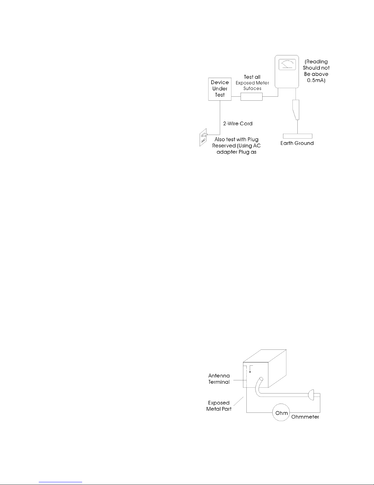
(3) Leakage Current Hot Check-With the instrument
completely reassembled, plug the AC line cord
directly into a 120V AC outlet. (Do not use an
isolation transformer during this test.) Use a
leakage current tester or a metering system that
complies with American National Standards
institute (ANSI) C101.1 Leakage.
Current for Appliances and underwriters
Laboratories (UL) 1270 (40.7). With the
instrument’s AC switch first in the ON position and
then in the OFF position, measure from a known
earth ground (metal water pipe, conduit, etc.) to all
exposed metal parts of the instrument (antennas,
handle brackets, metal cabinets, screwheads,
metallic overlays, control shafts, etc.), especially
and exposed metal parts that offer an electrical
return path to the chassis.
Any current measured must not exceed 0.5mA.
Reverse the instrument power cord plug in the
outlet and repeat the test.
AC Leakage Test
Any measurements not within the limits specified
herein indicate a potential shock hazard that must
be eliminated before returning the instrument to
the customer.
(4) Insulation Resistance Test Cold Check-(1) Unplug
the power supply cord and connect a jumper wore
between the two prongs of the plug. (2) Turn on
the power switch of the instrument. (3) Measure
the resistance with an ohmmeter between the
jumpered AC plug and all exposed metallic
cabinet parts on the instrument, such as
screwheads, antenna, control shafts, handle
brackets, etc. When an exposed metallic part has
a return path to the chassis, the reading should be
between 1 and 5.2 megohm. When there is no
return path to the chassis, the reading must be
infinite. If the reading is not within the limits
specified, there is the possibility of a shock hazard,
and the instrument must be re-pared and
rechecked before it is returned to the customer.
Insulation Resistance Test
- 2 -

2) Read and comply with all caution and safety related
notes non or inside the cabinet, or on the chassis.
3) Design Alteration Warning-Do not alter of add to the
mechanical or electrical design of this instrument.
Design alterations and additions, including but not
limited to, circuit modifications and the addition of
items such as auxiliary audio output connections,
might alter the safety characteristics of this
instrument and create a hazard to the user. Any
design alterations or additions will make you, the
service, responsible for personal injury or property
damage resulting there from.
4) Observe original lead dress. Take extra care to
assure correct lead dress in the following areas:
(1) near sharp edges, (2) near thermally hot parts
(be sure that leads and components do not touch
thermally hot parts), (3) the AC supply, (4) high
voltage, and (5) antenna wiring. Always inspect in
all areas for pinched, out-of-place, or frayed wiring.
Do not change spacing between a component and
the printed-circuit board, Check the AC power
cord for damage.
5) Components, parts, and/or wiring that appear to
have overheated or that are otherwise damaged
should be replaced with components, parts and/or
wiring that meet original specifications.
Additionally determine the cause of overheating
and/or damage and, if necessary, take corrective
action to remove and potential safety hazard.
6) Product Safety Notice-Some electrical and
mechanical parts have special safety-related
characteristics which are often not evident from
visual inspection, nor can the protection they give
necessarily be obtained by replacing them with
components rated for higher voltage, wattage, etc.
Parts that have special safety characteristics are
identified by shading, an (
) or a ( ) on
schematics and parts lists. Use of a substitute
replacement that does not have the same safety
characteristics as the recommended replacement
part might created shock, fire and/or other
hazards. Product safety is under review
continuously and new instructions are issued
whenever appropriate.
1-2 Servicing Precautions
CAUTION: Before servicing Instruments covered by
this service manual and its supplements, read and
follow the Safety Precautions section of this manual.
Note: If unforeseen circument create conflict between
the following servicing precautions and any of the
safety precautions, always follow the safety
precautions. Remember; Safety First
1-2-1 General Serving Precautions
(1) a. Always unplug the instrument’s AC power cord
from the AC power source before (1) removing or
reinstalling any component, circuit board, module
or any other instrument assembly. (2)
disconnecting any instrument electrical plug or
other electrical connection. (3) connecting a test
substitute in parallel with an electrolytic capacitor
in the instrument.
b. Do not defeat any plug/socket B+ voltage
interlocks with which instruments covered by this
service manual might be equipped.
c. Do not apply AC power to this instrument and/or
any of its electrical assemblies unless all
solid-state device heat sinks are correctly
installed.
d. Always connect a test instrument’s ground lead
to the instrument chassis ground before
connecting the test instrument positive lead.
Always remove the test instrument ground lead
last.
Note: Refer to the Safety Precautions section
ground lead last.
(2) The service precautions are indicated or printed on
the cabinet, chassis or components. When
servicing, follow the printed or indicated service
precautions and service materials.
(3) The components used in the unit have a specified
flame resistance and dielectric strength.
When replacing components, use components
which have the same ratings, by (
) or by ( )
in the circuit diagram are important for safety or
for the characteristics of the unit. Always replace
them with the exact replacement components.
(4) An insulation tube or tape is sometimes used and
some components are raised above the printed
wiring board for safety. The internal wiring is
sometimes clamped to prevent contact with
heating components. Install such elements as
they were.
(5) After servicing, always check that the removed
screws, components, and wiring have been
installed correctly and that the portion around the
serviced part has not been damaged and so on.
Further, check the insulation between the blades
of the attachment plus and accessible conductive
parts.
- 3 -

1-2-2 Insulation Checking Procedure
Disconnect the attachment plug from the AC outlet and
turn the power ON. Connect the insulation resistance
meter (500V) to the blades of the attachment plug. The
insulation resistance between each blade of the
attachment plug and accessible conductive parts (see
note) should be more than 1 Megohm.
Note: Accessible conductive parts include metal
panels, input terminals, earphone jacks, etc.
1-3 ESD Precautions
Electrostatically Sensitive Devices (ESD)
Some semiconductor (solid static electricity) devices
can be damaged easily by static electricity.
Such compo9nents commonly are called
Electrostatically Sensitive Devices (ESD). Examples of
typical ESD devices are integrated circuits and some
field-effect transistors and semiconductor chip
components. The following techniques of component
damage caused by static electricity.
(1) immediately before handling any semiconductor
components or semiconductor-equipped assembly,
drain off any electrostatic charge on your body by
touching a known earth ground. Alternatively,
obtain and wear a commercially available
discharging wrist strap device, which should be
removed for potential shock reasons prior to
applying power to the unit under test.
(2) after removing an electrical assembly equipped
with ESD devices, place the assembly on a
conductive surface such as aluminum foil, to
prevent electrostatic charge buildup or exposure
of the assembly.
(3) Use only a grounded-tip soldering iron to solder or
unsolder ESD device.
(4) Use only an anti-static solder removal devices.
Some solder removal devices not classified as
“anti-static” can generate electrical charges
sufficient to damage ESD devices.
(5) Do not use freon-propelled chemicals. These can
generate electrical charges sufficient to damage
ESD devices.
(6) Do not remove a replacement ESD device from its
protective package until immediately before you
are ready to install it. (Most replacement ES
devices are packaged with leads electrically
shorted together by conductive foam, aluminum
foil or comparable conductive materials).
(7) Immediately before removing the protective
materials from the leads of a replacement ES
device touch the protective material to the chassis
or circuit assembly into which the device will be
installed.
CAUTION: Be sure no power is applied to the chassis
or circuit, and observe all other safety precautions.
(8) Minimize bodily motions when handling
unpackaged replacement ESD devices.
(Otherwise harmless motion such as the brushing
together of your clothes fabric or the lifting of your
foot from a carpeted floor can generate static
electricity sufficient to damage an ESD device).
- 4 -
2. Reference Information
2-1 Component Descripti
ons
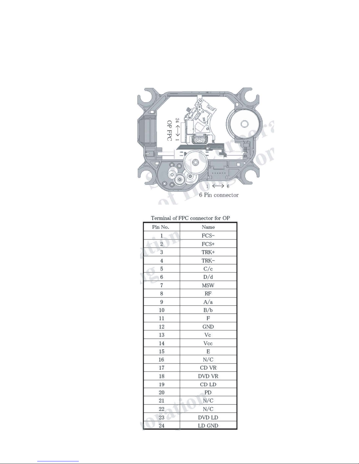
2-1-1 DVD
SONY HM 313-
Conn
ector Pin Definition
-5-
PUH
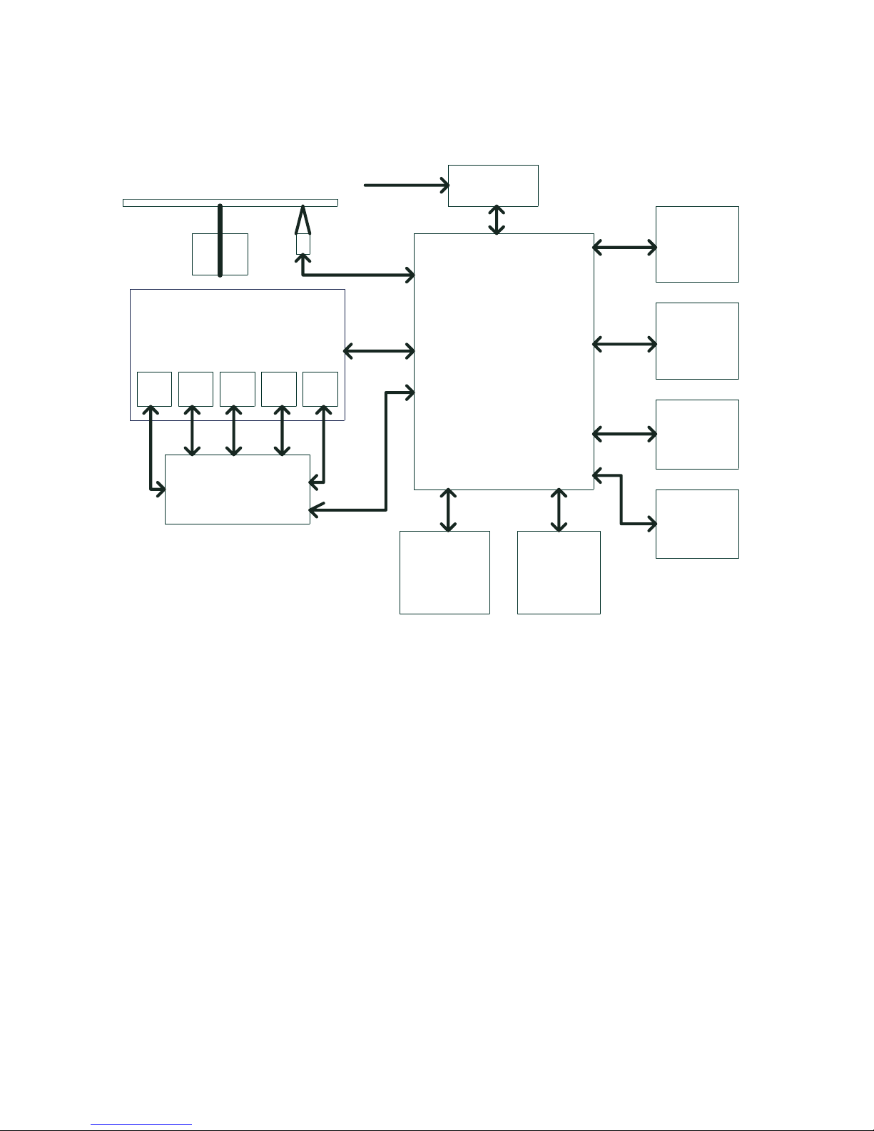
Block Diagram
- 6 -
MORPEE
y
romeM
ksai
F
M
ORD
S
r
e
d
a
o
L
csiD
061L92A M
61
e
ldni
p
S
ro
t
oM
sucoF
l
io
C
kcar
T
lioC
dei
S
r
oto
M
gnid
a
o
L
rot
oM
S
8
885
A
e
vir
D ro
to
M
E/F
9
8
3
1
TM
I
P
ATA
)o
v
res
/edoceD(
r
eganaM reffu
B
rotaludome
D
ILP
gnikcarT&sucoF
gnidao
L
61C4
2
M4 χ 61
o
idu
A
re
i
f
i
l
p
mA
F/I
nno
C
)
lenn
ap tnof
(
l
a
ng
iS C
I
M
n
ois
r
evn
oC D/A
23
6
2
E
C
tup
tuo
oedi
V
V
U
Y
o
ed
i
V
-
S
AGV
TR
AC
S
oediV
F
R

2-1-2 DVD Processor Chip MTK1389E/F
Features
Super Integration DVD player single chip
z High performance analog RF amplifier
z Servo controller and data channel processing
z Disc compatibility: DVD, DVD-R, DVD-RW, DVD+R, DVD+RW, Audio CD, CD-R, CD-RW, VCD, SVCD,
MP3-CD, MP3-DVD, PCM, JPEG-CD, JPEG-DVD
z Format compatibility:MPEG-1, MPEG-2, MPEG-4,
DivX 3.11, DivX 4.x, DivX5.x (Need licence), Xvid,
MP3, WMA, PCM, and JPEG & AVI
Dolby Digital, DTS
z Unified memory architecture
z Versatile video scaling & quality enhancement
z OSD & Sub-picture
z 2-D graphic engine
z Global motion compensation (GMC)
z Quarter pixel accurate motion Compensation (Q-PEL)
z B-frame
z Higher bit-rate up to 10 Mbps
z Full function remote control
z Plays regional code encrypted (RCE) DVDs
z Selectable 4:3 Pan & Scan or 16:9 Widescreen format
z PAL & NTSC playback
z Multi-speed FF/ RW, slow motion & multi level zoom
High Performance Analog RF Amplifier
z Programmable fc
z Dual automatic laser power control
z Defect and blank detection
z RF level signal generato
- Audio
z Dolby Digital (AC -3)/EX decoding
z DTS/DTS -ES decoding
z MLP decoding for DVD-Audio
z MPEG-1 layer 1/layer 2 audio decoding
z MPEG-2 layer1/layer2 2-channel audio
z High Definition Compatible Digital (HDCD)
z Windows Media Audio (WMA)
z Advanced Audio Coding (AAC)
z Dolby ProLogic II
z Concurrent multi-channel and downmix out
z IEC 60958/61937 output
-TV Encoder
z Six 108MHz/12bit DACs
z Support NTSC, PAL-BDGHINM, PAL-60
z Support 525p, 625p progressive TV format
z Automatically turn off unconnected channels
z Support PC monitor (VGA)
z Support Macrovision 7.1 L1, Macrovision 525P
z and 625P
- 7 -

RF Amplifier
DVD
PUH
Module
Servo IO
Spindle
Control
Servo
Processor
Memory
Controller
FLASH
ROM
DRAM
GPIO
Video
Processor
108MHz
TV Encoder
Video DAC
CVBS, Y/C
Component
Video
System
Parser
MPEG-1/2
JPEG
Video Decoder
Audio
DSP
Audio
Ouptut
Debug
Port
SDPIF
Audio
DAC
System
CPU
IR/VFD
De-
interlacer
CPPM/CPRM
DRM
32-bit
RISC
Motor
Drive
PCM
Audio DAC
Audio out
Functional Block
-8-
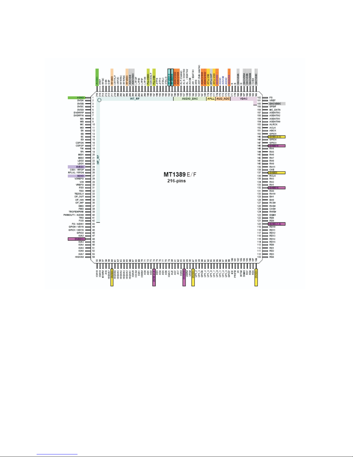
* Pinout Diagram
-8-
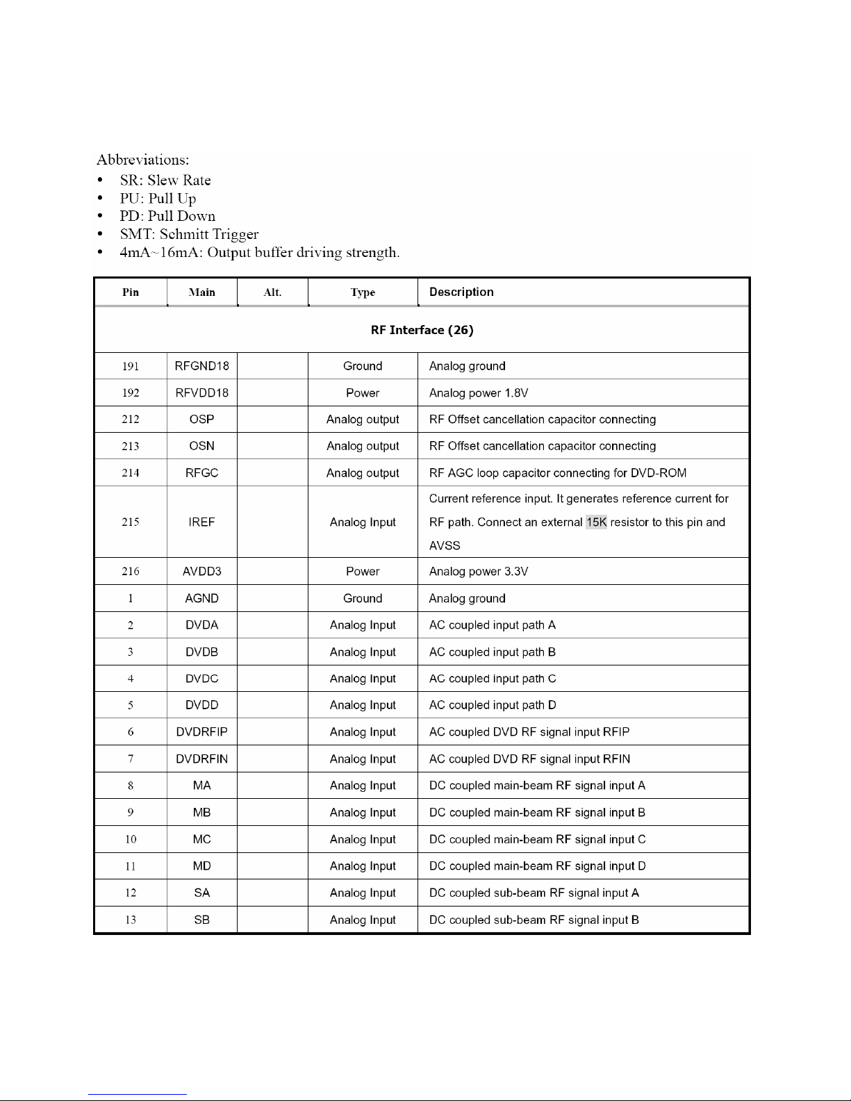
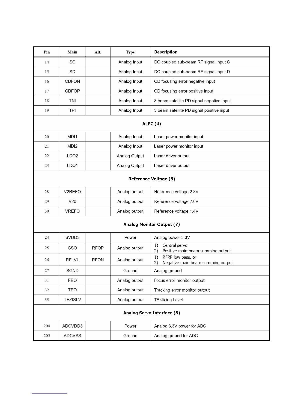
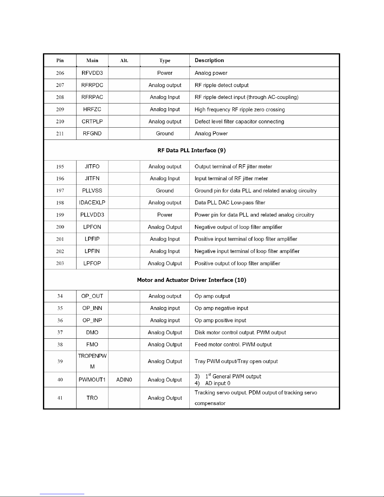
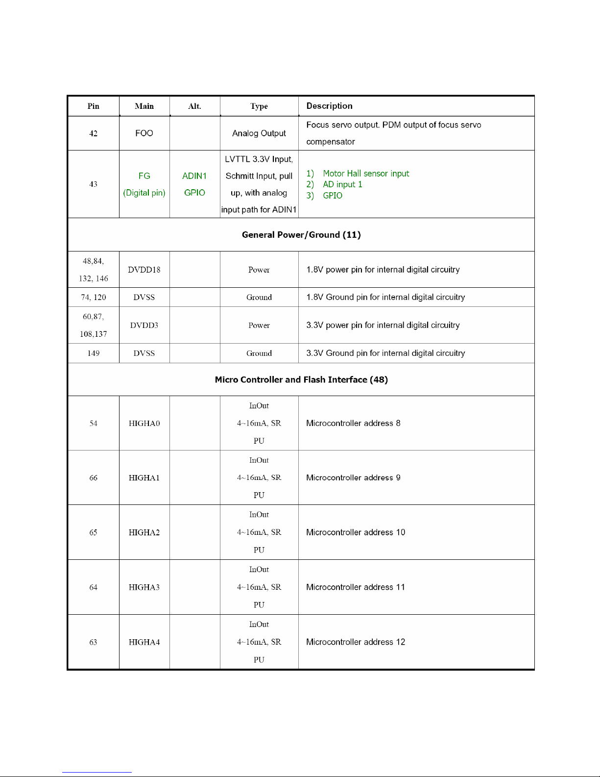
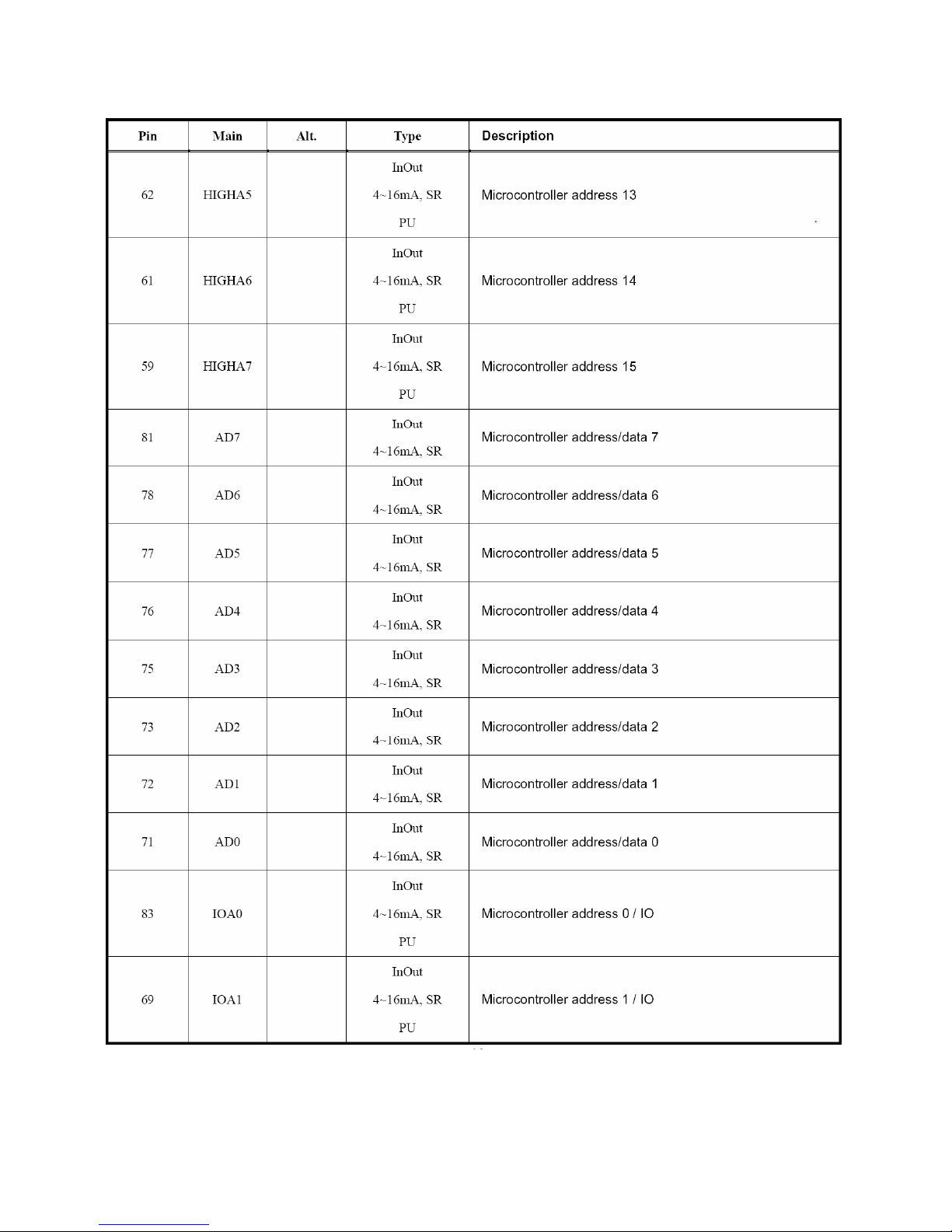
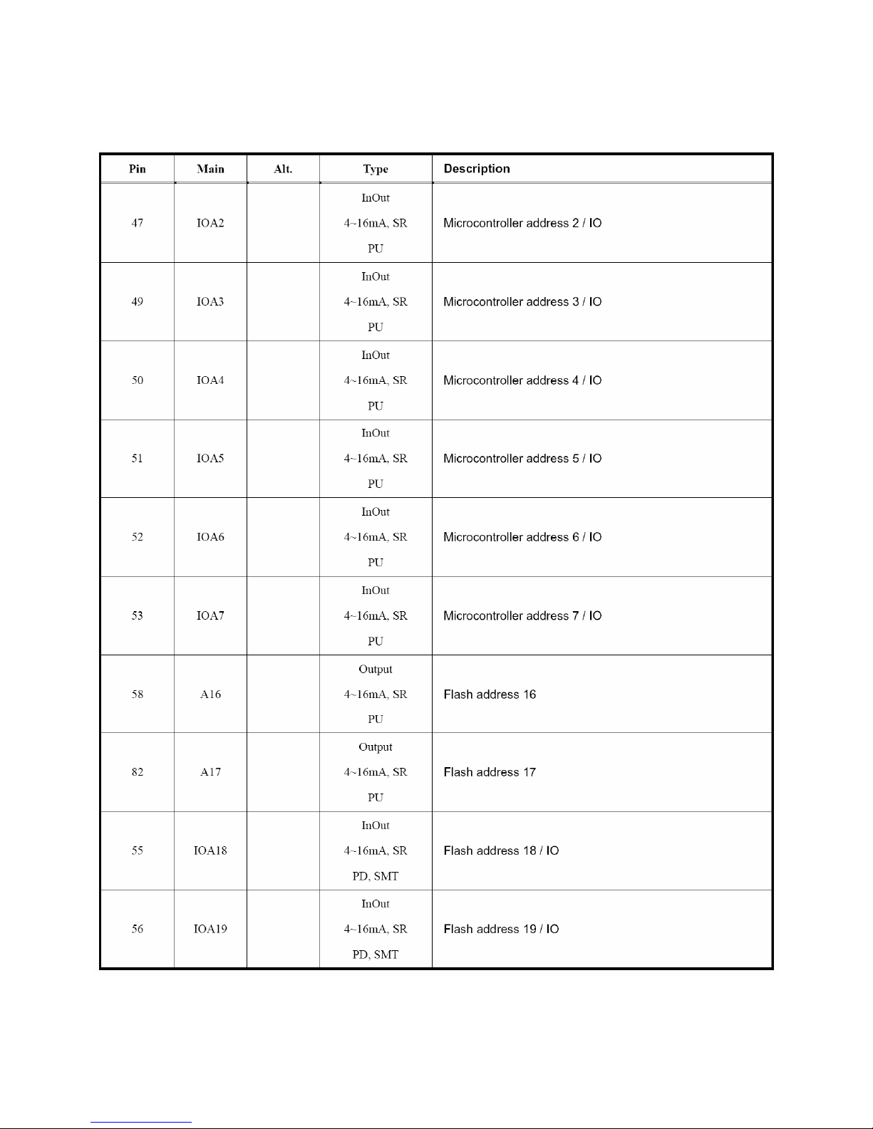
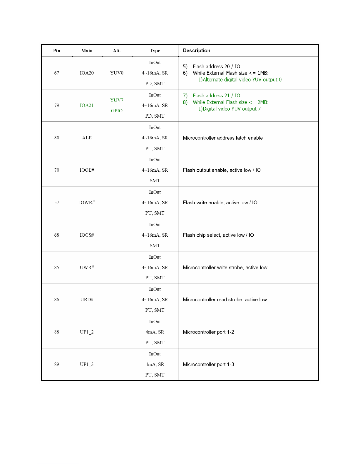
PIN DESCRIPTON
- 10 -
- 11 -
- 12 -
- 13 -
- 14 -
- 15 -
- 16 -
 Loading...