


do not output the film on this page
please turn next page
RT2300-rev.1 7/27/99 7:01 PM Page 1
POWER/STANDBY
PHONES
TEST / SET UP
P.SCAN
TUNING
TREBLE
BASS
VIDEO
S-VIDEO
PRESET EQ
SURR.MODE
AUDIOLR
POWER/STANDBY
SAT DVD
Audio Video
Integrated Receiver
CD
PHONES
VCR 2
TVTAPE
LEVEL
VCR 1 AM/FMVCR 2
M
O
D
E
/
S
E
T
D
E
M
O
M
U
L
T
I
J
O
G
D
I
G
I
T
A
L
S
O
U
N
D
P
R
O
C
E
S
S
O
R
C
O
N
C
E
R
T
O
F
F
N
I
G
H
T
C
H
U
R
C
H
A
R
E
N
A
T
H
E
A
T
E
R
DIGITAL
Digital
Sound
Processor
E/F/S (Rev. 1)
55021630
RT2300-rev.1 7/27/99 7:01 PM Page 2
TEST / SET UP
P.SCAN
TUNING
TREBLE
BASS
VIDEO
S-VIDEO
PRESET EQ
SURR.MODE
AUDIO
LR
SAT DVD
Audio Video
Integrated Receiver
CD
VCR 2
TVTAPE
LEVEL
VCR 1 AM/FMVCR 2
M
O
D
E
/
S
E
T
D
E
M
O
M
U
L
T
I
J
O
G
D
I
G
I
T
A
L
S
O
U
N
D
P
R
O
C
E
S
S
O
R
C
O
N
C
E
R
T
O
F
F
N
I
G
H
T
C
H
U
R
C
H
A
R
E
N
A
T
H
E
A
T
E
R
DIGITAL
D
igital
S
ound
P
rocessor
usermanual
RT2300/RT2300R
RT2400/RT2400R
Audio/Video Receiver
RT2300-rev.1 7/27/99 7:01 PM Page 3
1
FCC Information
This device generates and uses radio frequency (RF) energy, and if not installed and used properly, this
equipment may cause interference to radio and television reception.
This equipment has been type tested and found to comply with the specifications in Subpart J of Part 15 of
FCC Rules. These rules are designed to provide reasonable protection against radio and television
interference in a residential installation. However , there is no guarantee that interference will not occur in
particular installations.
If this equipment does cause interference to radio or television reception (which you can determine by
turning the equipment off and on), try to correct the interference by one or more of the following measures:
• Reorient the receiving antenna (that is, the antenna for the radio or television
that is "receiving" the interference).
• Move the unit away from the equipment that is receiving interference.
• Plug the unit into a different wall outlet so that the unit and the equipment
receiving interference are on different branch circuits.
If these measures do not eliminate the interference, please consult your dealer or an experienced
radio/television technician for additional suggestions.
Also, the Federal Communications Commission has prepared a helpful booklet, "How To Identify and Resolve
Radio TV Interference Problems." This booklet is available from the U.S. Government Printing Office,
Washington, DC 20402. Please specify stock number 004-000-00345-4 when ordering copies.
For Your Safety
The AC power plug is polarized (one blade is wider than the other) and only fits into AC power outlets one
way. If the plug won’ t go into the outlet completely, turn the plug over and try to insert it the other way. If it
still won’t fit, contact a qualified electrician to change the outlet, or use a different one. Do not attempt to
bypass this safety feature.
CAUTION: TO PREVENT ELECTRIC SHOCK, MATCH WIDE BLADE OF PLUG TO WIDE SLOT,
FULLY INSERT .
For Your Records
In the event that service should be required, you may need both the model number and the serial number . In
the space below, record the date and place of purchase, and the serial number:
Model No. RT2300/RT2300R/RT2400/RT2400R
Remote Control No. CRK76AD1
Date of Purchase
Place of Purchase
Serial No.
Service Information
This product should be serviced only by those specially trained in appropriate servicing techniques. For
instructions on how to obtain service, refer to the warranty included in this Guide
GB
WARNING : TO PREVENT FIRE
OR ELECTRICAL SHOCK HAZARD,
DO NOT EXPOSE THIS PRODUCT
TO RAIN OR MOISTURE.
CAUTION
RISK OF ELECTRICSHOCK
DO NOT OPEN
THE LIGHTNING FLASH
AND ARROW HEAD WITHIN
THE TRIANGLE IS A
WARNING SIGN ALERTING
YOU OF "DANGEROUS
VOLTAGE" INSIDE THE
PRODUCT.
CAUTION: TO REDUCE THE RISK OF
ELECTRIC SHOCK, DO NOT REMOVE
COVER (OR BACK). NO USER
SERVICEABLE PARTS INSIDE. REFER
SERVICING TO QUALIFIED SERVICE
PERSONNEL.
THE EXCLAMATION POINT
WITHIN THE TRIANGLE IS A
WARNING SIGN ALERTING
YOU OF IMPORTANT
INSTRUCTIONS
ACCOMPANYING THE
PRODUCT.
SEE MARKING ON BOTTOM/BACK OF PRODUCT
RT2300-rev.1 7/27/99 7:01 PM Page 4
2
Contents
GB
FCC Information . . . . . . . . . . . . . . . .1
Getting Started . . . . . . . . . . . . . . . . .3
Unpack the Receiver . . . . . . . . . . . . . . . . . .3
Inserting batteries into remote control . . . . . .3
Set up and Maintenance of the Receiver
. . . . . . . . . . . . . . . . . . . . . . . . . . . . . . . . . . . .3
Connecting to Audio-Visual
Components . . . . . . . . . . . . . . . . . . . . . . . . .4
Connecting the Antennas . . . . . . . . . . . . . .6
Connecting the speakers . . . . . . . . . . . . . .6
Subwoofers . . . . . . . . . . . . . . . . . . . . . . . . . . . . . .6
Positioning your speakers . . . . . . . . . . . . .7
Connecting for power . . . . . . . . . . . . . . . . .8
Using Headphones . . . . . . . . . . . . . . . . . . . .8
Demo Mode . . . . . . . . . . . . . . . . . . . . . . . . . .8
Restore to Factory Settings . . . . . . . . . . . .8
How to Operate your Receiver . . . . .9
Receiver Controls . . . . . . . . . . . . . . . . . . . . .9
Y our Remote Contr ol . . . . . . . . . . . . . . . . .10
The Built-in Radio . . . . . . . . . . . . . . . . . . . .11
Seek Tuning . . . . . . . . . . . . . . . . . . . . . . . . . . . . .11
Storing and Recalling Stations in Memory . . .11
Using the Receiver to Play DVD . . . . . . . .12
Using the Receiver to Play CD . . . . . . . . .12
Using the Receiver to Play Video Cassette
. . . . . . . . . . . . . . . . . . . . . . . . . . . . . . . . . . .12
Using the Remote to Control additional
components . . . . . . . . . . . . . . . . . . . . . . . .12
Advanced Sound Control . . . . . . . .13
Dolby Pro Logic and Dolby 3 Stereo . . . .13
Dolby Digital . . . . . . . . . . . . . . . . . . . . . . . .13
Setting up the Speakers . . . . . . . . . . . . . .13
The Test Tone / Setup button . . . . . . . . . . . . . .13
Input IQ . . . . . . . . . . . . . . . . . . . . . . . . . . . .14
Night Mode . . . . . . . . . . . . . . . . . . . . . . . . .14
Auto Detect . . . . . . . . . . . . . . . . . . . . . . . . .14
Demo Mode . . . . . . . . . . . . . . . . . . . . . . . . .14
Program Format Display . . . . . . . . . . . . . .14
Care and Maintenance . . . . . . . . . .15
Tr oubleshooting Tips . . . . . . . . . . . . . . . . .15
Receiver/Tuner Operation . . . . . . . . . . . . . . . . .15
Remote Control Operation . . . . . . . . . . . . . . . .15
General . . . . . . . . . . . . . . . . . . . . . . . . . . . . . . . .15
Cleaning the Exterior . . . . . . . . . . . . . . . .15
Equipment Specifications . . . . . . . . . . . . .15
Remote Codes . . . . . . . . . . . . . . . . .16
Cable Codes . . . . . . . . . . . . . . . . . . . . . . . . . . . .16
VCR Codes . . . . . . . . . . . . . . . . . . . . . . . . . . . . . .16
TV Codes . . . . . . . . . . . . . . . . . . . . . . . . . . . . . . .17
Satellite Receivers . . . . . . . . . . . . . . . . . . . . . . .18
Audio (RCA/Dimensia only) . . . . . . . . . . . . . . .18
Laserdisc Players . . . . . . . . . . . . . . . . . . . . . . . . .18
Index . . . . . . . . . . . . . . . . . . . . . . . .19
US Warranty . . . . . . . . . . . . . . . . . .20
Canadian Warranty . . . . . . . . . . . . .21
RT2300-rev.1 7/27/99 7:01 PM Page 5
Unpack the Receiver
Check that you received the following items with
the receiver:
• one receiver unit;
• one RCA Universal Remote Control
(CRK76AD1);
• one external FM Dipole antenna;
• one external AM loop antenna;
• one instruction book;
• one owner registration/survey card;
• and one safety leaflet.
• one pair of AA batteries;
• one audio cable (two wires) with red and
white RCA connectors;
• one video cable (single wire) with yellow
RCA connectors;
The following additional items are especially for
RT2300 or RT2400 with speaker set:
• one pair of main speakers;
• one center speaker;
• one pair of surround speakers;
• one powered subwoofer;
• five speaker cable;
• one monoaural audio cord for subwoofer;
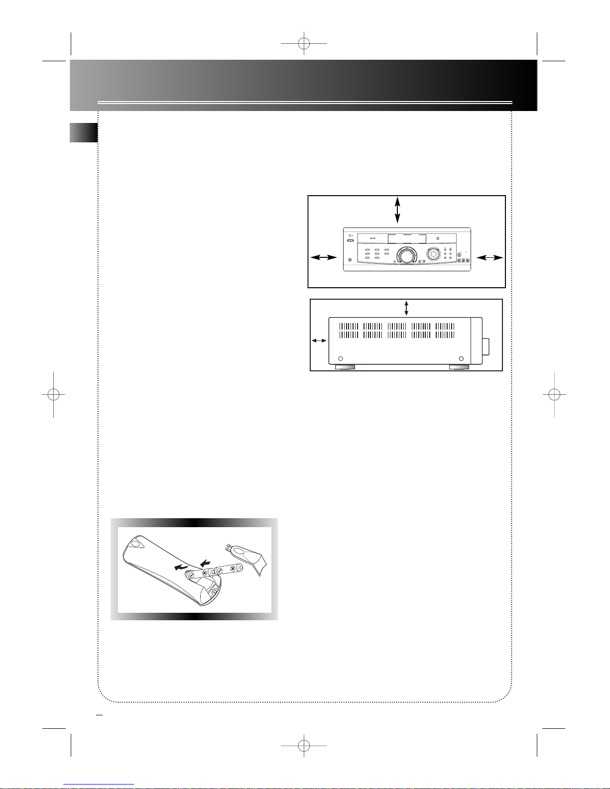
Inserting batteries into
remote control
Insert two AA(R6) batteries with the + and - on the
battery compartment. To use the remote control, point
it directly at your receiver .
Set up and Maintenance of
the Receiver
• Provide spaces for sufficient ventilation as
indicated:
• Do not connect to the AC power cords until
all of the connection are completed.
• Do not use your set immediately after transfer
from a cold place to a warm place: risk of
condensation.
• Do not expose your set to water projections and
excessively high temperatures.
• After having disconnected your set, clean the case
with a soft cloth, or with a slightly humid chamois
leather . Never use strong solvents.
3
Getting Started
GB
10 cm
10 cm10 cm
10 cm
5 cm
TEST/SET UP
P.SCAN
TUNING
TREBLE
BASS
VIDEO
S-VIDEO
PRESETEQ
SURR.MODE
AUDIOLR
POWER/STANDBY
SAT DVD
AudioVideo
IntegratedReceiver
CD
PHONES
VCR2
TVTAPE
LEVEL
VCR1 AM/FMVCR2
M
O
D
E
/
S
E
T
D
E
M
O
M
U
L
T
I
J
O
G
D
I
G
I
T
A
L
S
O
U
N
D
P
R
O
C
E
S
S
O
R
C
O
N
C
E
R
T
O
F
F
N
I
G
H
T
C
H
U
R
C
H
A
R
E
N
A
T
H
E
A
T
E
R
DIGITAL
D
igital
S
ound
P
rocessor
RT2300-rev.1 7/27/99 7:01 PM Page 6
4
Getting Started
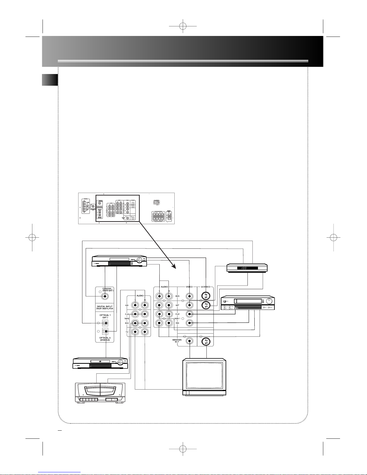
Connecting to Audio-Visual
Components
This receiver allows you to connect to a large variety
of audio or video components.
Before you Connect
• Protect components from power surges.
• Connect all components before plugging any
power cords into the wall outlet.
• Always turn off the receiver and/or components
before you connect or disconnect any cables.
• Contact Consumer Relations if you have questions
concerning the connections or components.
Note: If you purchase the receiver with speaker set
(i.e. RT2300, RT2400), please make sure the colorcoded pins match the color of the terminals in which
they are inserted. The connection cable plugs and
jacks are color-codes as follows:
Speaker T erminals T o ease speaker connections
the speaker cords and the terminals are color-coded
into: Red/Black (Main Speakers), Blue/Black (Center
Speakers) and Grey/Black (Rear Speakers). When
connecting the speakers, make sure the color of
speaker wires and terminals are matched.
RCA Phono T ype Terminals Red for the right (R)
channel. White for the left (L) channel. Yellow for the
video. Black for the subwoofer .
Positioning the Cables
Cables should be positioned correctly to avoid audio
hum or interference. A few suggestions below:
• Insert all cable plugs firmly into their jacks.
• Place audio/video cables to the sides of the
receiver’s back panel instead of straight down the
middle after you connect the components.
• Try not to coil any power cables and keep them
away from the audio/video cables as much as possible.
• Make sure all antennas and cables are properly
grounded.
Protect your Components from
Overheating
• Do not block ventilation holes in any component.
Arrange the components so that air can circulate
freely.
• Do not stack components directly on top of each
other .
• Allow adequate ventilation when placing your
components in a stand.
• Place an amplifier near the top shelf of the stand
so heating air rising from it will not flow around other
components. If you have a satellite receiver , you
should place it on the top shelf.
(continued on next page -> )
GB
RT2300-rev.1 7/27/99 7:01 PM Page 7
GB
5
Getting Started
Tips:
1. If your CD player is equipped with digital optical jacks, using
optical cable is preferred. What you need is just one more optical
digital connecting cord(not supplied). Plug it in the digital input
jack of the receiver and you can enjoy better sound quality
brought you by the optical cable. When optical cable is used, no
more analog cable is needed.
2. If you have a video camera, video game machine, or an extra
VCRs, connect it to VCR 2 jack at the front of the receiver.
3. If you have a Direct TV System receiver or DVD player, you can
make use of an optical digital connecting cord (not supplied) or
coaxial digital connecting cord (not supplied) to enjoy Dolby
Digital sound quality . One optical / coaxial cable is needed for each
SAT receiver / DVD player. When optical cable is used, no more
analog cable is needed.
Note: The optical cable jack is for either DVD or CD. If you have
plugged in the optical cable for DVD, use the analog cable for CD,
or unplug the optical cable from DVD and plug it in CD when use.
4. If your video component has a S-Video jack included, you can
make use of it to enjoy enhanced video quality by connecting it to
the relevant S-Video jack at the rear side of the receiver. 1 video
cable is needed for each component. When S-Video cable is used,
no more analog video cable is needed.
Note: Before plugging in the optical cable or S-Video cable, make
sure to match the shape of the plug and jack, or you won’t be able
to plug in completely.
TV
DVD
To AUDIO OUTPUT
To VIDEO OUT
To VIDEO IN (VCR)
To AUDIO IN (VCR)
To AUDIO OUT
To
AUDIO
OUT
To
VIDEO
OUT
To AUDIO OUT
with
Optical
Cable
with
Optical
Cable
with
Coaxial
Cable
VCR
To
VIDEO IN
CD Player
To
S-VIDEO IN
To S-VIDEO OUT
Tape Deck
To
S-VIDEO
OUT
To
VIDEO
OUT
To
AUDIO
OUT
Direct TV
System
receiver
with Coaxial Cable
with Optical Cable
To LINE OUT
To LINE IN
(Tape Deck)
TAPE
A
UT
O
M
AT
IC
RE
CO
RD
LE
VE
L
A
UT
O
ST
OP
M
EC
H
A
NI
S
M
1
>
2
Y
A
L
P
S
U
O
U
NI
T
N
O
C
O
N
E
T
O
U
C
H
R
E
C
O
R
DI
N
G
1
>
2
G
NI
B
B
U
D
E
P
A
T
RECORD PLAY REW F.FWD STOP / EJECT PAUSE PLAY STOP / EJECT
PLAYBACK/ PLAYBACK
1
TAPE
2
RT2300-rev.1 7/27/99 7:01 PM Page 8
 Loading...