

Page 1
Page 2
This device complies with Part 15 of the FCCRules.
Operation is subject to the following two condi-
tions: (1) This device may not cause harmful
interference, and (2) this device must accept any
interference received, including interference that
may cause undesired operation.
In accordance with FCCrequirements, changes or
modifications not expressly approved by Thomson
multimedia Inc. could void the user's authority to
operate this product.
This device generates and uses radio frequency (RF)
energy, and if not installed and used properly, this
equipment may cause interference to radio and
television reception.
If this equipment does cause interference to radio
or television reception (which you can determine by
unplugging the unit), try to correct the interference
by one or more of the following measures:
• Re-orient the receiving antenna (that is,the
antenna for the radio or television that is
"receiving" the interference).
• Move the unit away from the equipment that is
receiving interference.
° Plug the unit into a different wall outlet so that
the unit and the equipment receiving interference
are on different branch circuits.
If these measures do not eliminate the interference,
please consult your dealer or an experienced
radio/television technician for additional
suggestions. Also, the Federal Communications
Commission has prepared a helpful booklet, "How
To Identify and Resolve Radio TV Interference
Problems." This booklet is available from the U.S.
Government Printing Office, Washington, DC 20402.
Please specify stock number 004-000-00345-4 when
ordering copies.
This product complies with DHHS Rules 21 CFR
Subchapter J. Applicable at the date of
manufacture.
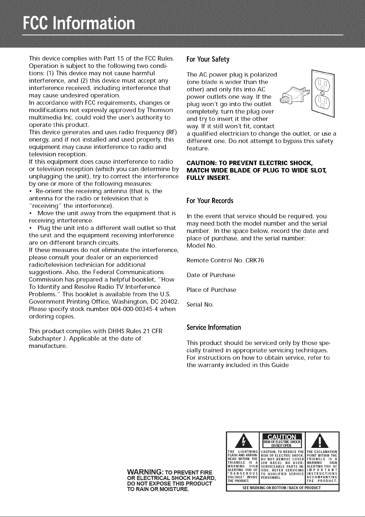
ForYour Safety
The AC power plug is polarized
(one blade is wider than the
other) and only fits into AC
power outlets one way. If the
plug won't go into the outlet
completely, turn the plug over
and try to insert it the other
way. If it still won't fit, contact
a qualified electrician to change the outlet, or use a
different one. Do not attempt to bypass this safety
feature.
CAUTION: TO PREVENT ELECTRIC SHOCK,
MATCH WIDE BLADE OF PLUG TO WIDE SLOT,
FULLY INSERT.
ForYourRecords
In the event that service should be required, you
may need both the model number and the serial
number. In the space below, record the date and
place of purchase, and the serial number:
Model No.
Remote Control No. CRK76
Date of Purchase
Place of Purchase
Serial No.
ServiceInformation
This product should be serviced only by those spe-
cially trained in appropriate servicing techniques.
For instructions on how to obtain service, refer to
the warranty included in this Guide
WARNING: TO PREVENT FIRE
OR ELECTRICAL SHOCK HAZARD,
DO NOT EXPOSE THIS PRODUCT
TO RAIN OR MOISTURE.
THE LiGHTNiNG
FLASH AND ARROW-
HEAD WiTHiN THE
TRIANGLE IS A
WARNING SmGN
ALERTING YOU OF
"DANGEROUS
VOLTAGE" iNSiDE
THE PRODUCT.
CAUTION: TO REDUCE THE
RISK OF ELECTRIC SHOCK
DO NOT REMOVE COVER
(OR BACK). NO USER-
SERVICEABLE PARTS iN-
SIDE. REFER SERVICING
TO QUALIFIED SERVICE
PERSONNEL.
SEEMARKING ON BOTTOM IBACK OF PRODUCT
THE EXCLAMATION
POINT WITHIN THE
TRIANGLE iS A
WARNING SIGN
ALERTING YOU OF
MPORTANT
NSTRUCTIONS
ACCOMPANYING
THE PRODUCT.
Page 3
FCC Information
Getting Started
Unpacking the Receiver ............. 2
Unpacking the Speakers (RT2280 Only)..3
Inserting Batteries into Remote Control .3
Set Up and Maintenance of the
Receiver .......................... 3
Protect your Components from
Overheating ....................... 3
Connecting to Audio-Visual
Components ...................... 4
Digital Connection ................. 5
Connecting Antennas ............... 5
Connecting the Speakers ............. 6
Connecting the Subwoofer ........... 6
Positioning your Speaker ............. 7
Front Speaker Placement ............. 7
Surround Placement ................ 8
Advanced Surround Setting .......... 8
Test Tone / Channel Balance .......... 9
Connecting for Power ............... 9
Using Headphones .................. 9
Factory Setting ..................... 9
Care and Maintenance
Troubleshooting Tips ............... 23
Receiver/Tuner Operation .......... 23
Remote Control Operation ......... 23
General ........................ 23
Cleaning the Exterior ............. 23
Equipment Specifications .......... 23
Remote Codes
Cable Codes ...................... 24
VCR Codes ....................... 24
TV Codes ........................ 25
Satellite Receivers ................. 26
Audio (RCA only) .................. 26
Laser disc Players .................. 26
Limited Warranty (US) ......... 27
Limited Warranty (Canada) ..... 28
Operating your Receiver
Receiver Controls .................. 10
Your Remote Control ............... 11
Display .......................... 12
Switching On/Off .................. 13
Selection of Audio/Video Source ...... 13
Using the Remote to Control Additional
Components ...................... 14
Using the receiver to play a Source .... 15
Advanced Sound Control
Sound Enhancement Systems ........ 19
Fine Setting of Components ......... 20
Fine Setting of the Speakers ......... 21
Advanced Setting ................. 21
Page 4
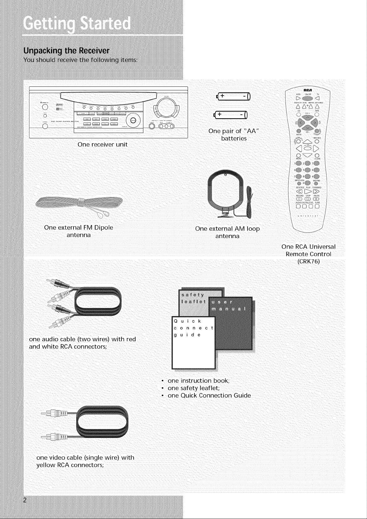
One receiver unit
-0
-0
One pair of "AA"
batteries
DW,_CHVC_ _.FM S_-CA_LE
AA°AS
_@_@_@
°EVERSEPLm FORWAR_
_ECORDSTOP PAUSE
One external FM Dipole
antenna
one audio cable (two wires) with red
and white RCA connectors;
One external AM loop
antenna
One RCA Universal
Remote Control
(CRK76)
• one instruction book;
• one safety leaflet;
• one Quick Connection Guide
one video cable (single wire} with
}/ellow RCA connectors;
Page 5
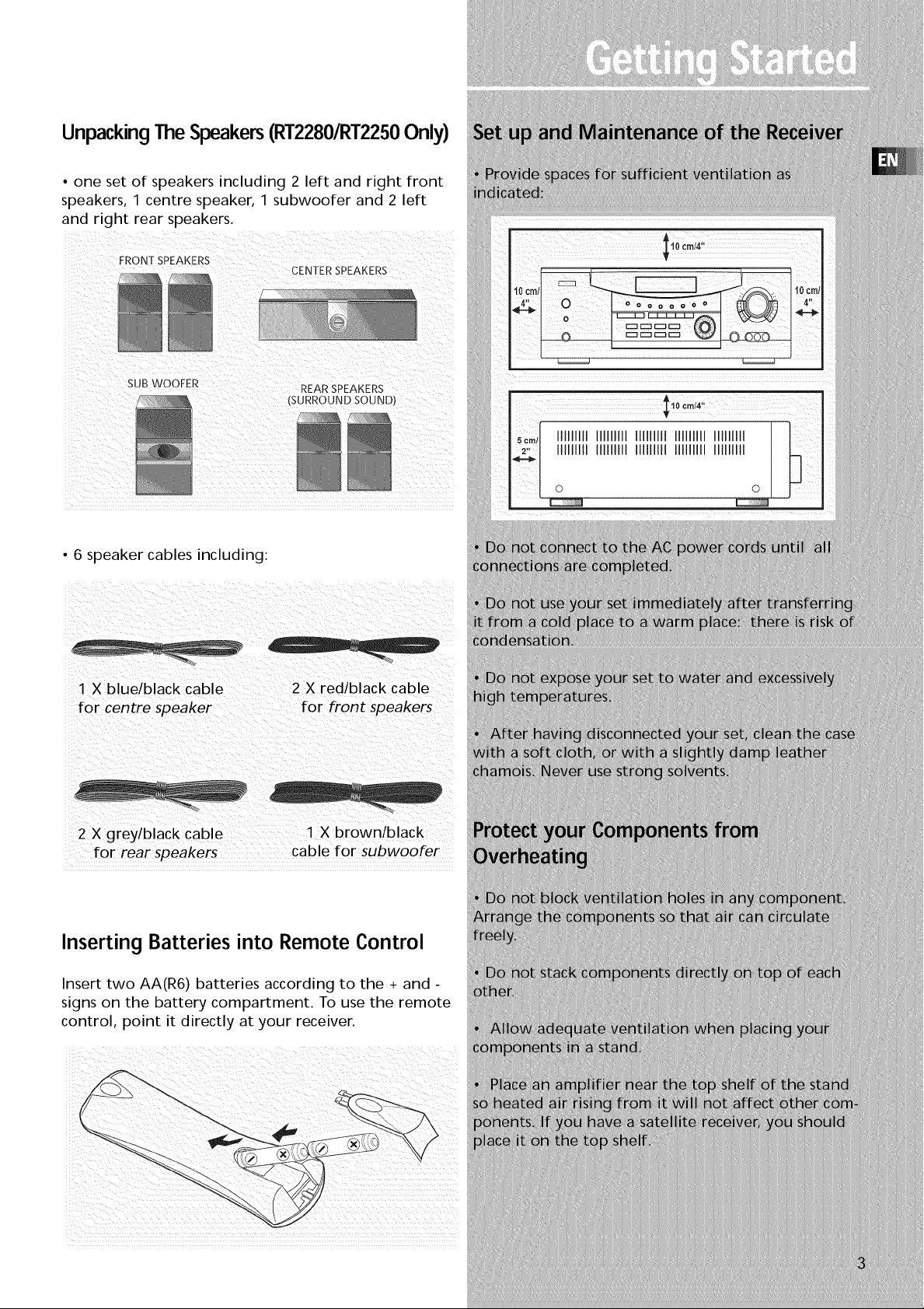
UnpackingTheSpeakers(RT2280/RT2250Only)
• one set of speakers including 2 left and right front
speakers, 1 centre speaker, 1 subwoofer and 2 left
and right rear speakers.
SUB WOOEER REAR SPEAKERS
° 6 speaker cables including:
2 X greyiblack Cable
for rear speakers ..............cable for subwoofer
Inserting Batteries into Remote Control
Insert two AA(R6) batteries according to the + and -
signs on the battery compartment. To use the remote
control, point it directly at your receiver.
i:i( C( ¸¸¸ !::? (i ii¸
ii i
Page 6

S-VIDEO
If your video component has a S-Video jack
included, you can make use of itte enjoy
enhanced video quality by connecting it to the
relevant S-Video jack at the rear side of the
receiver. One video cable s needed for eacn
component. When S-Video cable is used.
composite video (yellow RCA connector) cable
must also be connected for VCR recording.
Note: Before plugging in the optical cable or
S-Video cable "hake sure to match the shape of
the plug and jack. otherwise you will not be able
to plug in completely.
DVD
_'_'- I to S-VIDEO OUT DVD/
I I I_ _D--
$_ t_UDIOOUT_DVD
DIGIT iNPUT-- 12
Connect components
capab e of outputing d
tal (e.g. DVD
or SAT) ' standard ,'_
PC[V Iformat digital ,o
signals. Read section on
"lnpu qal Setting"
nd _ __'unae vanced Sou .' _L Multi-cI
Control" carefully to 6 -- Deco,
adj matching . o _ e.g.c
input settings. _
O
DIGITAL CONNECTION
If you have a SAT receiver DVD player or CD player with a digital output, you can make
use of an optical digital connecting cord (net supplied) or coaxial digital connecting
cord (net supplied) to carry the audio portion of the signal and enjoy Delby Digital
sound quality. One optical or coaxial cable is needed for each SAT receiver. DVD
player or CD player. When optical or coaxial cable is used. the analog audio cables are
still needed if recording through a tape or VCR is desired. This receiver provides one
optical and one coaxial digital input for the connection of your components. Please
connect your components (e.g. DVD. SAT or CD) to the appropriate digital inputs and
press FUNCTION and then rotate MULTI JOG to match your connection.
Note: Optical and coax cables carry only the audio portion of the signal. Avidee
connection must also be established for a SAT receiver and DVD player. S-video
provides the best connection for the video portion of the signal. Composite video
(yellow RCA connector) can also be used. It is
important that the same type of cable (S-video or composite/that is connected from the
Home Theater to the TV is used to connect the SAT receiver or DVD player to the
Home Theater.
to S-VIDEO
UNIT
BACK PANEL
CD Player
/
If your CD player is equipped with digits optical jacks, use of optical cable is preferred.
What you need is just one more optical digital connecting cord(not supplied). Plug it in
".he digital input jack of the recewer and select OPTICAL on the receiver setting (see
details on Dg 20 chapter "Input Signal Setting"). You can enjoy better sound quality
brought to you by the optical cable. When optical cable is used, analog cables are sti
needed for recording to tape output.
Note: This receiver has one digital optical jack only. Be sure that such connection does
not prevent optical cable connection of other components (e.g. DVD & SAT_
to VIDEO tN _TV
to AUDIO OUT
VCR
.....III lpO
FRONT TERMINAL I
Remark If you have a video
camera, video game machine, or an I
extra VCR, connect it to VCR 2 jack
at the front of the rece ver 1
Page 7
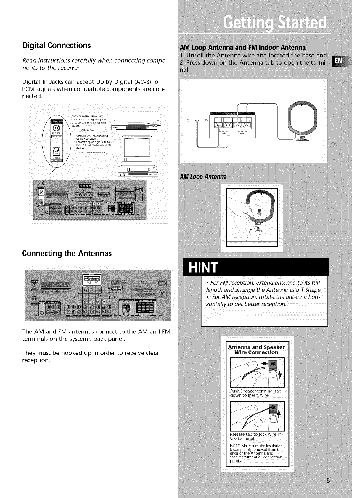
Digital Connections
Read instructions carefully when connecting compo-
nents to the receiver.
Digita n Jacks can accept Dolby Digital (AC-3), or
PCM signals when compatible components are con-
nected.
COAXIAL DIGITAL iN (AUDIO)
Connect to coaxial dig tal output of ....
/
Connecting the Antennas
The AM and FM antennas connect to the AM and FM
terminals on the system's back panel.
They must be hooked up in order to receive clear
reception.
Page 8

SUB WOOFER
back panel to connect
anotner powerea
subwoofer other than
Use _nls jack on the left
the one supplied.
CENTER
SPEAKER
FRONTSPEAKERS
REAR SPEAKERS(SURROUNDSOUND)
To ease speaker connections, the speaker cords and
the terminals are color-coded.
• Red/Black (Front Speakers),
• Blue/Black (Center Speaker)
• Grey/Black (Rear Speakers).
• Brown/Black (Subwoofer)
Connect the L, R speaker (with red/black terminal) on
the back of the speakers to the corresponding color
on the receiver. Do the same for center (with
blue/black terminal), rear speaker (with grey/black
terminal) and the subwoofer (with brown/black ter-
minal).
Speaker Polarity
When connecting the speakers, make sure the polari-
ties ("+" speaker wire to "+" on the receiver) of
speaker wires and terminals are matched. If the cords
are reversed, the sound will be distorted and will lack
bass ("out of phase" effect).
Connecting the Subwoofer
For RT2280/RT2250, connect the subwoofer with the
speaker cord (brown/black) provided. For RT2250R,
or if you want to connect your own powered sub-
woofer, a mono aural audio cord (not supplied) is
needed (RCA terminal).
Antenna and Speaker
Wire Connection
Push Speaker terminal tab
down to insert wire.
This receiver offers a high flexibility for user to use a
large variety of speakers and subwoofers. For more
information please refer to section "Fine Setting of
the Speakers" in "Advanced Sound Control" on page
21.
Release tabto lock wire in
the terminal.
NOTE: Make sure the insulation
is completely removed from the
ends of the Antenna and
speaker wires at all connection
points .
Page 9
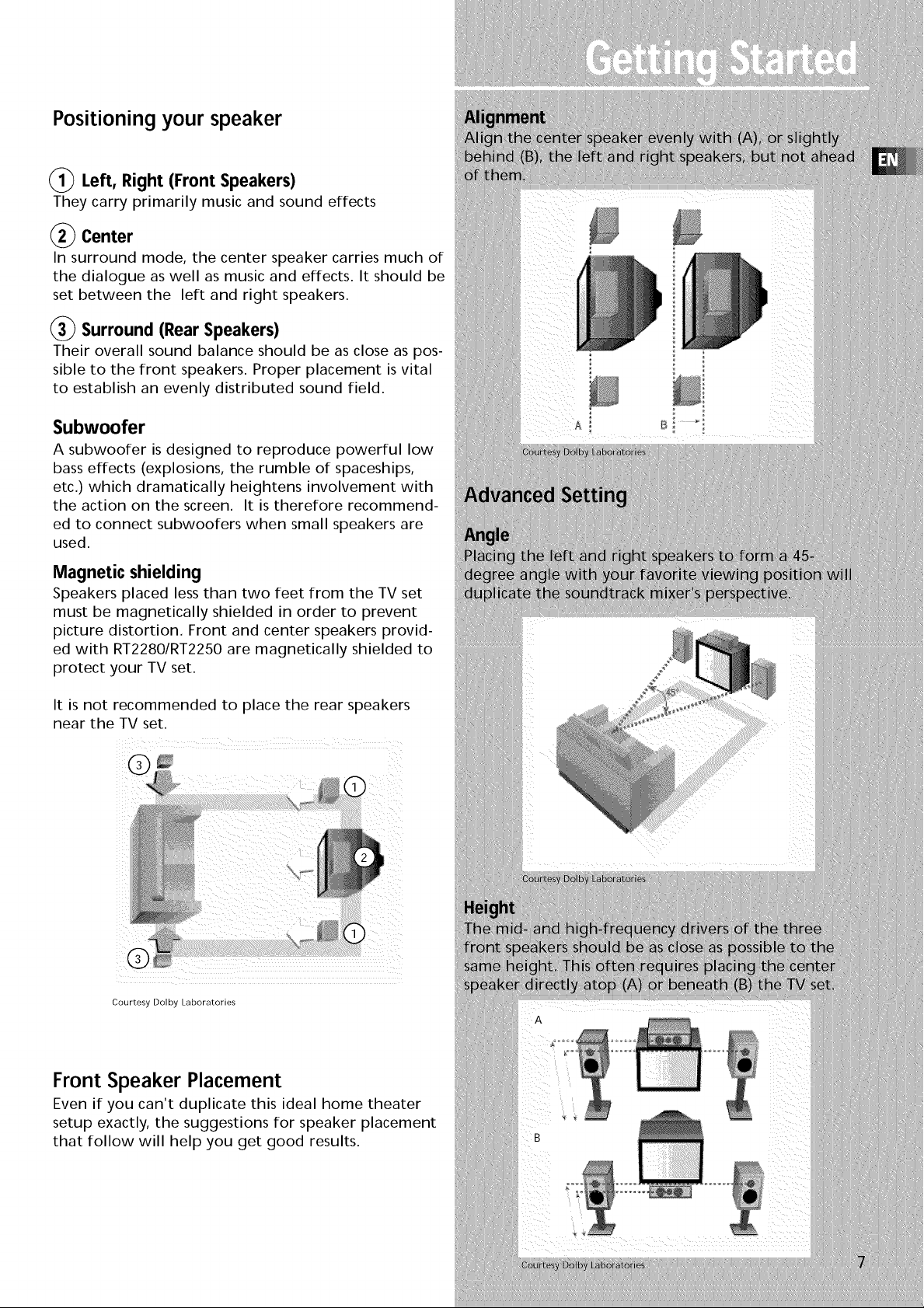
Positioning your speaker
(_ Left, Right (Front Speakers)
They carry primarily music and sound effects
(_ Center
In surround mode, the center speaker carries much of
the dialogue as well as music and effects. It should be
set between the left and right speakers.
_) Surround (Rear Speakers)
Their overall sound balance should be as close as pos-
sible to the front speakers. Proper placement is vital
to establish an evenly distributed sound field.
Subwoofer
A subwoofer is designed to reproduce powerful low
bass effects (explosions, the rumble of spaceships,
etc.) which dramatically heightens involvement with
the action on the screen. It is therefore recommend-
ed to connect subwoofers when small speakers are
used.
Magnetic shielding
Speakers placed less than two feet from the TV set
must be magnetically shielded in order to prevent
picture distortion. Front and center speakers provid-
ed with RT2280/RT2250 are magnetically shielded to
protect your TV set.
It is not recommended to place the rear speakers
near the TV set.
Courtesy Dolby Laboratories
i!ii_
Front Speaker Placement
Even if you can't duplicate this ideal home theater
setup exactly, the suggestions for speaker placement
that follow will help you get good results.
B
Page 10
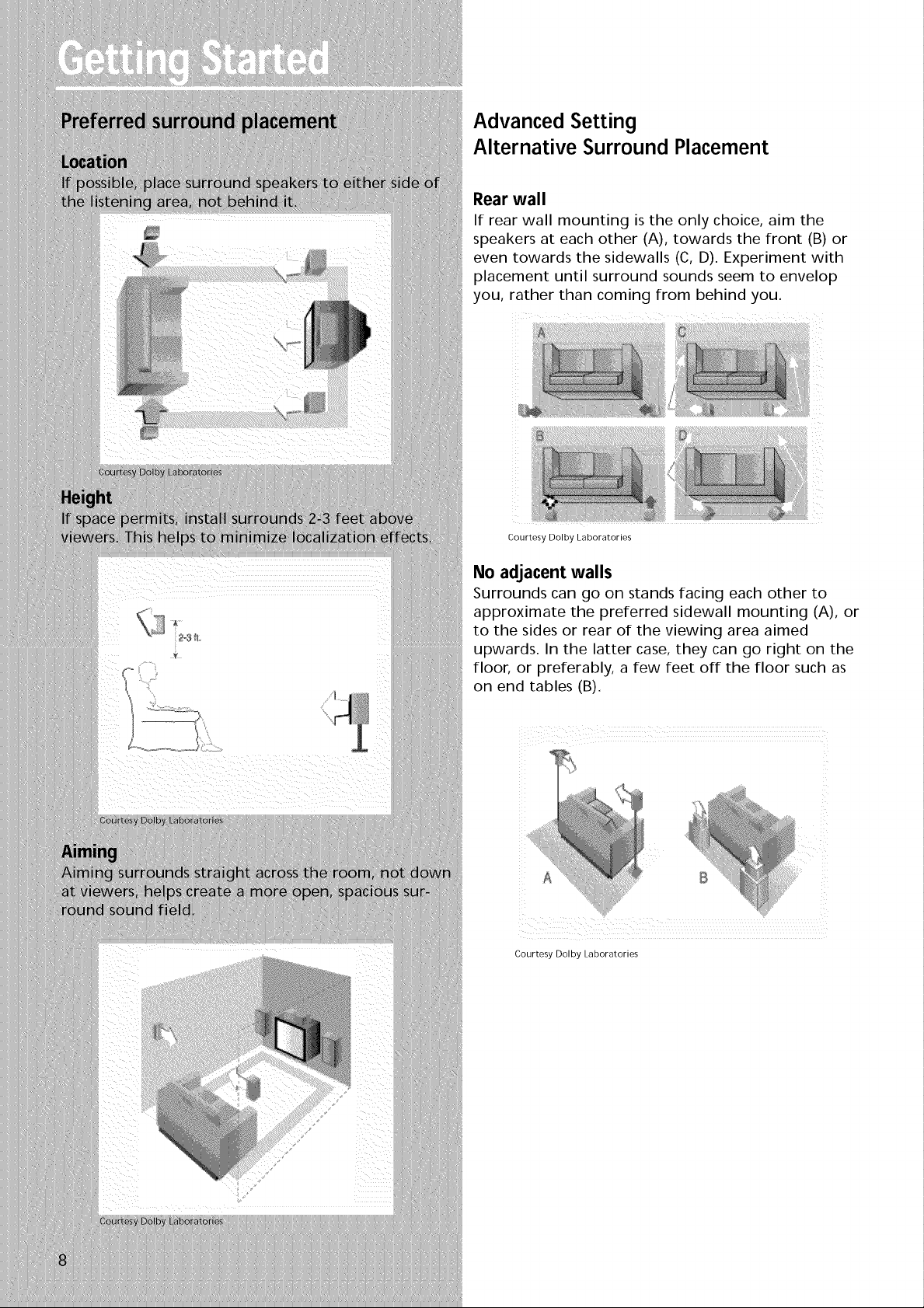
Advanced Setting
Alternative Surround Placement
Rear wall
If rear wall mounting is the only choice, aim the
speakers at each other (A), towards the front (B) or
even towards the sidewalls (C, D). Experiment with
placement until surround sounds seem to envelop
you, rather than coming from behind you.
iiili
ii
Courtesy Dolby Laboratories
No adjacent walls
Surrounds can go on stands facing each other to
approximate the preferred sidewall mounting (A), or
to the sides or rear of the viewing area aimed
upwards. In the latter case, they can go right on the
floor, or preferably, a few feet off the floor such as
on end tables (B).
i _ '_ i iiii ii
i iiiiiiii i i i
Courtesy Dolby Laboratories
Page 11

TestTone / Channel balance
Channel balance
Your receiver is equipped with a test signal generator
for balancing the channels. As the signal "travels"
from channel to channel, adjust the level controls
until each channel plays at the same loudness level.
(details see operation of test/setup)
Courtesy Dolby Laboratories
Level adjustment & surround channel level expec.
tation
Even though you adjust the surround channel to be
as loud as the others on the test signal, you'll find
that on actual program material the surround chan-
nel is usually much lower than the front. Don't be
tempted to readjust the surround level; program pro-
ducers use surround mostly for subtle atmosphereics
and ambience, and only rarely for special effects. A
good surround mix doesn't call attention to itself; if
it did, it would soon become distracting.
The system is equippe d with DoIby Digita!,
and manufactured under License from Dolby
Laboratories.
BEI[oo'B"i 0i0i o,
D I G I T A L license fromDolby
"Pro Logic" and the double-D symbol are trade-
marks of Dolby Laboratories. Copyright 1992-
1997 Dolby Laboratories, Inc. All Rights Reserved.
Manufactured under
Laboratories. "Dolby",
Page 12

o- .......................I I__l .......i,.......i ( _ )1 ...._....._......._ i
• In DIM selection, you can rotate to set the brightness of the
display. Such setting will be stored.
• Use MULTI JOG for speakers and sub-woofers setup and pre-
set radio stations selection.
9. TUNING
Pressfor about 2 seconds to activate Automatic Preset function.
Pressonce to review all preset stations.
10. R SCAN (Preset Scan)
• Pressand hold for about 2 seconds to start the automatic
tuner station preset.
• Pressto view preset stations one by one.
11. SURR. MODE
Pressrepeatedly to select the surround mode you want. ( refer
to "Advanced Sound Control" on page 20.)
12. 6 CH (6 Channels External Input)
Pressto select the input connected to an external 6-Channel
decoder. Pressagain to return to the most recently selected
source mode. (see 6 Channel External Input on page 11).
13. TEST/SET UP
When pressing it briefly, a short noise (test tone) will be gener-
ated in the speakers one by one so that you can adjust the vol-
ume of individual speaker. When keep pressing for two sec-
onds, it will enter setup mode for speakers and subwoofers.
Rotate the MULTI JOG to choose the options. (refer to "The
TEST/SETUP button" on page 21.)
14. PRESET EQ
Pressrepeatedly to select the desirable EQ mode (music style) -
CLASSIC,POR ROCK, JAZZ, VOCAL or FLAT.Your choice will be
saved automatically.
15. BYPASS
Pressto go back to stereo sound (no DSPeffect, no sound from
center and surround speakers)
16. VCP2/Video Cam Input
For convenient use of your digital camera, family game
machines, second VCR, etc.
Page 13

Your Remote Control
Please be sure you have inserted the batteries into the
remote control (see relevant section on page 3.) You can
test it by pressing any button. If it works, the red LED
will light.
MUTE
D
Fq 0_0
MENU CLEAR
10 _0 _0
,o _o 0o
l_0 _,0_Ol
NPUT.SEEK ,_ ANT,FMS
@0(_ 0
RECORD STOP PAUSE
AUDIODIGITALLEVEL SURR
D
[!N
/
/
/
Page 14

DSP
• Unit is in DSP (Digital Sound Processing) mode.
• Speaker Icons.
SLEEP
• Unit in Sleep mode.
MEMORY
• Unit in Memory mode.
Kl-lz
Ml-lz
° Tuner frequency unit.
Page 15

Switching on/off
• To switch on the receiver, press STANDBY/ON but-
ton (1) once. Alternatively, you can press any of the
source buttons to power on the receiver.
• Standby: when the receiver is on, press the
STANDBY/ON button once to activate the standby
mode.
• To switch off the unit completely, unplug the
power cord from the socket
Your receiver has a back up memory to keep
your settings like preset radio station for
about 2 weeks in case electricity cut occurs. If
the receiver is unplugged for more than 2
weeks, aft the settings wifl be lost and re-set-
ting wifl be necessary.
Page 16

Using the Remote to Control Additional
Components
You can set your remote to control other components
(like CD, TV, DVD, TAPE, etc.). What you need is to
encode them in advance (not necessary for recent
RCA & Proscan models).
1. Turn on the component to be programmed.
2. Look up the brand and corresponding code num-
ber in the code list from page 24 to 26.
3. Press and hold the corresponding Source Button
(like VCR1, VCR2, TV, BVD) on the remote while
entering the code from the code list using the
Number Buttons.
4. Release the compo-
nent button, then press
ON,OFF to see if the
component will be
turned off.
5. If this does not work, repeat steps 3 and 4 by try-
ing to use the next code (if available) listed for the
brand of your component until the component
responds to the remote command.
Page 17

Once your remote is encoded, you can press
ON/OFFon the remote Once tO tUrn Off the
component and then followed by the second
time quickly to
unit). If you onty want the receiver to be
turned oFf, setect FM/AM while the unit is ON:
This remote may not operate all models oF
the brands shownl
iFbatteries removed from the battery
compartment of the remote control, aft mem-
ory wilt be lost. You need to re.enter all ....
previously programmed codes ac "
Thebuttons on the remote may not work
Correspondingly with those on Other brand
components. Experiment with the remote and
your components to see which buttons work
if only a few functions operatel check tO Seeif
Page 18

5- Tune the stations by pressing TUNING UP or
DOWN repeatedly until the desired station is found.
Alternatively, you can press and hold TUNING UP or
DOWN for about one second to activate the
automatic SEARCH function. In this mode the receiver
will automatically tune frequencies until it finds a
station
7. Repeat steps 5 or 6 to tune another radio station.
Select sound effect if needed by pressing Preset EQ or
DSP sound (see "Advance sound section" for details)
1. If there is interference, modify the location
of the antenna until the optimal sound isheard.
TVand other electronic devices could be the
cause of interferences so try to position the
antenna away of them.
2. Weak signal can affect the "auto Search
function". Adjust the antenna for better recep-
tion for more efficient search.
Page 19

Storing radio stations:
The receiver can store up to 30 radio stations in
memory. You can enter every single radio station
yourself or the receiver can store all available radio
station automatically in an ascending order.
Automaticpresetstoring:
1. Select the band wave by pressing AM/FM
repeated ly
2- Press and hold
P.SCAN for 3 seconds.
"MEMORY" will be dis-
played in red and will
blink during the auto-
matic storing process.
I
Radio frequencies will be browsed and radio station
stored automatically. When all available radio sta-
tions are stored or if all 30 memory locations are full,
the auto preset will stop.
weak signal can affect the 'AUtomatic Preset
Storing-functio n flefficiency. Adjust the antenna I
for the best reception for more efficient search. I
Page 20

6 Channelexternalinput
An external decoder (Dts, Dolby Digital, etc...) or a
device with built-in multi-channel decoder and 6
channel output connector (DVD player, TV...) can be
connected to the 6CH input. It is therefore possible to
play any future 6 Channels coding (SACD, DVD
Audio) thanks to this connection. The external
decoder device will send the separated audio infor-
mation to the receiver that will then amplify the sig-
nal and send to appropriate speakers.
To activate 6 Channel external input, press 6 CH on
the receiver or press DVD/6 CH twice on the remote
control.
Page 21

Sound Enhancement Systems
This receiver is equipped with several built-in sound
enhancement systems.
Dolby Pro Logic and Dolby 3 Stereo
This surround system reproduces theater-like sur-
round sound from Dolby-encoded software. The Pro
Logic mode uses the built-in circuit to steer the Left,
Center, Right and Surround channel audio signals and
uses all five speakers and an optional subwoofer to
play decoded Dolby Pro Logic program source, such
as TV and VCR.
The 3 Stereo mode will redirect the Surround signals
to the front left and right speakers when only the
front and center speakers are used.
Use this mode to suit your speaker system configura-
tions (such as size and number of speakers) and type
of program (such as VCR).
Front Left SpeaKer Center Speaker l-rent Right SpeaKer
R_ _r Left SDenKel Rear RI ]ht SpeaKer
DD 3 Stereo
RontLeft _aKe C_nt_r _aK_ FmntRign_p_aK_r
Subwoofer
Page 22

Input Signal Setting
The receiver defaults to the most convenient settings
for your easiest use (see table).
If your connection is different from the default set-
ting,
1. Select the source
2. Press FUNCTION
3. Rotate MULTI JOG to toggle among optical/coaxi-
al/ analog to match your connection. Your selection
will be stored automatically.
Every time you press the source button, the input set-
ting (e.g. DVD/OPTI) will be shown on display for a
few seconds.
DEFAULT INPUT (as seen on display)
Coaxial (SAT/COAX)
Optical (DVD/OPTI)
Analog (CD/ANL)
Analog (VCR1/ANL)
Analog (VCR2/ANL)
Built-in Tuner
Analog (TAPE/ANL)
Analog (TV / ANL)
ur
Digital Input
Select this setting to play digital signals from a DVD,
CD, LD player, SAT or TV.
Analog Input
Select this setting to play analog signals from a cas-
sette deck, VCR or turntable.
AVAILABLE INPUT
ANL/Optical/Coaxial
ANL/Optical/Coaxial
ANL/Optical/Coaxial
ANL/- / -
ANL/- / -
ANL/- / -
ANL/Optical / -
Page 23

Fine Setting of the Speakers
This receiver supports a wide range of speakers and
subwoofers. For optimal surround sound enjoyment,
you need to register the speaker selection settings of
your audio system. If you buy this receiver with
accompanied speaker package, then this step has
been done for you.
Also, to make the surround sound more effective and
suit the acoustic conditions in your listening room,
you need to delay the signal from some of the speak-
ers. Such channel delay compensates for center or
surround speakers that are closer to listening position
than the front speakers. You can make use of the
TEST/SET UP button to adjust the speakers' relative
loudness.
The TEST/SETUP button
You can adjust the relative loudness of the individual
speakers by TEST/SET UP button. In Dolby modes,
press the button briefly. A short noise will be heard
in the speakers one by one. The speaker having the
noise at that moment will be shown in the display.
You can listen to that speaker and rotate the MULTI
JOG to adjust the level.
Advanced Setting
Factory defaulted Advance setting indication
from VFD
The receiver has defaulted the following distances:
_Cch
L/R_ _ /L/R
SUR/!_ -- J_SUR
/
• The sub-woofer selection will always be YES
when the main speakers are set to small
(SML).
• For the subwoofer phase setting, it will be
affected by how you locate the subwoofer.
Tryboth + and - settings and select the one
that has better bass effect.
• If your unit comes with speakers
(RT2280/2250),always set all speakers size to
"smafl" to protect them and optimize the
sound quality
Front speakers (L/R) 15 ft
Center speaker (Cch) 15 ft
Rear speaker (SUR) 10 ft
Page 24

Speaker Icons
The receiver shows you the speakers' types and set-
tings on the display with the following icons:
Displaying Program Formats
When a digital source is playing, the receiver will
automatically switch to the proper surround mode
and indicates on the speaker icons on the right-hand
side of the display. (See diagram)
It is important to note, however, that not all Dolby
Digital sources are encoded with the full complement
of five channels plus LFE*. Speaker icons show how
many and which speaker you have enabled (See "Fine
Setting of the Speakers") and the letters inside the
speaker icons show which channel is present in the
source information. For example, the diagram shown
means you have all the five speakers and subwoofer
enabled and the digital sources you played have five
channels plus LFEcomplemented.
* LFE stands for Low Frequency Effect. The indication
"LFE" appears if the digital source contains LFE infor-
mation. In this case, the bass signal will be delivered
to the subwoofer, offering more dynamic deep bass
sound effects. If the letter is flashing, the signal is
either too weak or just gone.
Page 25

Troubleshooting Tips
Receiver/Tuner Operation
STEREOindicator isoff.
• Adjust the antenna.
ThesignalisMono.Severehumor noise.
• The signal is too weak. Connect an external anten-
na.
Remote Control Operation
The remote control does not operate the unit.
• Another function mode is selected on the remote.
Press the correct Source Button.
• No batteries installed. (included with your system)
Install the batteries before attempting to operate the
remote. Be sure to match the + and - ends of each
battery to the symbols shown in the remote battery
compartment.
• The batteries are weak. Replace all batteries.
• The remote is not pointed at the remote control
sensor on the main unit or there is an obstacle
between the remote and the main unit.
• The remote control is too far from the main unit,
move closer.
General
Noaudio.
• Make sure the speakers are connected.
• Check the input connections.
° Check the power cord connections.
• Make sure the MUTE indicator on the front panel is
Off.
• Make sure the digital setting (optical, coaxial or
analog) is correct.
Noaudiofromonechannel
• Check the speaker level setting.
° Check the speaker wire or cable connections.
Noiseoccurswhenthe TVis turnedon.
• The TV istoo close to the audio system.
Specificinstrumentssounddisplaced.
• Check the connections between the receiver and
the speakers if the sound does not match the video.
• Press the Source Button for the video source.
Page 26

CABLE CODES
VCR CODES
ARCHER
CABLETENNA
CABLEVIEW
CENTURY
CITIZEN
COLOUR VOICE
COMTRON CS
CONTEC
EASTERN
GARRARD
GC ELECTRONICS
GEMINI
GENERAL INSTRUMENT
HAMLIN
HITACHI
HYTEX
MAGNAvOX
MEMOREX
MOVIE TIME
OAK
PANASONIC
PARAGON
PIONEER
PULSAR
RCA
REALISTIC
REGAL
REGENCY
REMBRANDT
RUNCO
SAMSUNG
i SCIENTIFIC ATLANTA
SIGNAL
SIGNATURE
SL MARX
SPRUCER
STARCOM
STARGATE
STARQUEST
TANDY
TELEVIEW
TOCOM
TOSHIBA
TUSA
UNIKA
UNITED ARTISTS
UNITED CABLE
UNIVERSAL
VIDEOWAY
V!EWSTAR
ZENITH
ADMIRAL
ADVENTURA
AIKO
AIWA
AKAI
2113
AMERICAN HIGH
ASHA
AUDIO DYNAMICS
AUDIOVOX
BELL & HOWELL
BEAUMARK
BROKSONIC
CALIX
CANDLE
CANON
CAPEHART
CARVER
CCE
CITIZEN
COLORTYME
COLT
CRAIG
CURTIS-MATHES
CYBERNEX
DAEWOO
DAYTRON
DBX
DIMENSIA
DYNATECH
ELECTROHOME
ELECTROPHONIC
EMERSON
FISHER
FUJI
FUNAI
GARRARD
GE
GOLDSTAR
GRADIENTE
HARLEY DAVIDSON
HARMAN KARDON
HARWOOD
HEADQUARTER
HITACHI
HI-Q
INSTANT REPLAY
JCI
JC PENNE¥
JENSEN
JVC
KENWOOD
KLH
KODAK
LLOYD
LOGIK
LXl
MAGNAVOX
MAGNIN
MARANTZ
MARTA
MASUSHITA
ME
2131
2026
2027
2002,
2026
2003,
2004,2005,2007,2008,2111,2112,
2021
2013
2009,
2010
2014
2011
2013
2025
2012,
2014
2013,
2014,2015,2016,2017,
2018,
2019
2021,
2022,2114
2110
2020,
2062
2061
2027,
2013,
2014,2015,2016,2017,
2018,
2019,2027
2009
2061
2013,
2014,2023,2061
2000,
2002,2009,2013,2016,
2018,
2021,2022,2024,2115
2013
2015,
2017,2019,2025,2026,
2027,
2028,2110
2110
2010
2009,
2000
2002,
2026
2029
2014,
2014
2002,
2012,2014,2015,2021,2024,2025,
2026,
2029,
2030,2032,2033,2034,2035,2036,
2037,
2038,
2039,2040,2041,2042,2044,2045,
2047,
2065,
2105,2113,2116,2117,2130
2011,
2023,2048,2049,2050,2051,2052,
2118
2021,
2119
2026
2002,
2026
2000,
2001,2013,2021,2022,2053,2115,
2120
2009,
2014,2018,2054,2121
2026
2026
2009
2061
2011
2002,
2055,2056,2057,2107,
2111,
2120,2122
2023
2021
2021
2009,
2010,2011,2013,2014,
2021,
2022,2055,2056,2058,
2059,
2060,2107,2118
2055,
2056,2111
2009,
2010,2011,2018,2058,
2123
2111,
2009,
2010,2011,2016,2018,
2058,
2111,2123
2061
2014,
2021
2026
2002,
2061
2014
2021,
2022,2062,2063,2104,
2108,
2124
2013
2009,
2010,2011,2016,2018,
2021,
2058,2062,2064
2014
2021
2021
Page 27

MEMOREX
MGA
MGNTECHNOLOGY
MIDLAND
MINOLTA
MITSUBISH
MONTGOMERYWARD
MOTOROLA
MTC
MULTITECH
NEC
NIKKO
NOBLEX
OLYMPUS
OPTIMUS
OPTONICA
ORION
PANASONIC
PENTAX
PENTEXRESEARCH
PHILCO
PHILIPS
PILOT
PIONEER
PORTLAND
PROSCAN
PROTEC
PULSAR
QUARTER
QUARTZ
QUASAR
RCA
RADOSHACK/REALISTIC
RADIX
RANDEX
RICOH
RUNCO
SAMSUNG
SANKY
SANSU
SANYO
SCOTT
SEARS
SHARP
SHINTOM
SHOGUN
SIGNATURE
SINGER
SONY
STS
SYLVANIA
SYMPHONIC
TANDY
TASHIKO
TATUNG
TEAC
TECHNICS
TEKNIKA
TMK
TOSHIBA
TOTEVSION
UNITECH
VECTORRESEARCH
VICTOR
VIDEOCONCEPTS
VIDEOSONIC
WARDS
XR-1000
YAMAHA
ZENITH
2002,
2104,
2029,
2013
2053
2055,
2029,
2070,
2123
2075,
2021,
2002,
2002,
2009,
2076,
2014
2013
2021
2014,
2096
2035
2021,
2016,
2018
2021,
2021,
2014
2010,
2016,
2000,
2061
2104
2011
2011
2021,
2000,
2082,
2089,
2002,
2026,
2014
2014
2128
2104
2005,
2104,
2010,
2011,
2012,
2093,
2011,
2051,
2002,
2004,
2013
2002,
2021,
2002,
2021,
2002,
2124
2002,
2002,
2014
2058,
2002,
2021,
2002,
2013,
2015,
2013,
2013
2009,
2010
2009,
2013
2002,
2029,
2103,
2021,
2009,
2004,
2011,2013,2014,2021,2023,2026,
2131
2065,2113
2056,2107
2055,2056,2065,2066,2067,2069,
2071,2072,2073,2074,2106,2113,
2131
2131
2013,2026
2013,2016,2026,2053,2061
2010,2011,2016,2018,2058,2064,
2078,2079,2111,2123
2131
2022,2109,2125,2126,2127
2055,2056,2107,2120
2022,2062,2063
2062,2096,2124
2055,2080,2081,2123
2017,2019,2110
2001
2022,2125
2001,2003,2013,2021,2055,2056,
2083,2084,2085,2086,2087,2088,
2090,2091,2107,2115,2120,2125
2011,2013,2014,2021,2022,2023,
2029,2049,2050,2096,2131
2013,2015,2033,2053,2112
2131
2092,2111,2123
2013,2023
2015,2025,2032,2035,2038,2065,
2116
2014,2021,2023,2048,2049,2050,
2055,2056,2107,2118
2017,2029,2094,2095,2096,2131
2056,2061,2098
2131
2061,2128
2004,2098,2099,2119,2128
2107
2021,2022,2026,2062,2063,2065,
2026
2011
2111
2026,2058,2085,2111
2109
2014,2021,2026,2100,2129
2024,2047
2049,2051,2055,2065,2093,2116
2014
2010,2015,2016
2010,2015,2016,2113
2013,2014,2015,2021,2023,2026,
2055,2056,2061,2096,2101,2102,
2107,2116,2131
2026,2061
2010,2011,2018,2058,2111
2098,2104,2119,2128
Page 28

KAWASHO
KAYPANI
KENWOOD
KLOSSNOVABEAM
KTV
LOEWE
LOGIK
LUXMAN
LXl
MAJESTIC
MARANTS
MARANTZ
MEGATRON
MEI
MEMOREX
MINUTZ
MITSUBISHI
MONTGOMERYWARD
MOTOROLA
MTC
MULTITECH
MULTIVISION
NAD
NEC
NIKKO
NTC
ONWA
OPTIMUS
OPTONICA
ORION
PANASONIC
PHILCO
PHILIPs
PILOT
PIONEER
PORTLAND
PRICE CLUB
PRISM
PROSCAN
PROTON
PULSAR
PULSER
QUASAR
RADIO SHACK/REALISTIC
RHAPSODY
RUNCO
SAMPO
SAMSUX
SANSUI
SANYO
SCOTCH
SCOTT
SHOGUN
SIGNATURE
SIMPSON
SONIC
SONY
SOUNDESIGN
SQUAREVIEW
SSS
STARLITE
SUPRE-MACY
SUPREME
SYLVANIA
SYMPHONIC
TAN DY
TATUNG
TECHNICS
TECHWOO :3
TEKNIKA
TELECAPTION
TMK
TOSH 8A
TOTEVISION
UNIVERSAL
VICTOR
VIDTECH
VIKING
WARDS
YAMAHA
ZENITH
1008
1176
1002
1004,
1006,1008,1038,1046
1189
1004,
1038
1038
1174
1002
1004,
1006,1008,1019,1062,1068,1069,
1074,
1075,1076,1077,1088,1116,1161,
1183,
1184
1033,
1038,1189
1173
1178
1003,
1054
1004,
1006,1054
1004,
1005,1006,1008,1012,1013,1016,
1038,
1046,1076,1082,1083,1105,1170,
1171
1117
1004,
1006
1049,
1071,1072,1089,1105,1109,1117,
1118,
1160,1162
1171
1052,
1087
1066,
1182
1004,
1005,1006
1174
1000,
1001,1004,1005,1006,1019,1024,
1033,
1046,1052,1062,1069,1074,1075,
1076,
1083,1087,1088,1095,1119,1120,
1184
1004,
1005,1006,1019
1004,
1083,1151,1152,1153,1154
Satellite Receivers
CHAPPARAL 5056, 5057
DRAKE 5058, 5059
GE SATELLITE RECEIVER 5000, 5001
GENERAL INSTRUMENTS 5060, 5061, 5062
PANASONIC SATELLITE RECEIVER
5075
PRIMESTAR DBS
PROSCAN SATELLITE RECEIVER
RCA SATELLITE RECEIVER 5000, 5001
REALISTIC 5063
SONY SATELLITE RECEIVER 5072
STS1 5064
STS2 5065
STS3 5066
STS4 5067
TOSHIBA 5068
TOSHIBA SATELLITE RECEIVER 5073
UNIDEN SATELLITE RECE VER 5069
5O76
5000,5001
Audio (RCA/Dimensia only)
AM/FM 4003
AUX 4004
PHONO 4005
CD 4007
TAPE 4006
Laser disc Players
PROSCAN 2001
RCA 2001
Page 29

What your warranty covers:
• Defects in materials or workmanship.
For how long after your purchase:
• One year from date of purchase for labor and parts
• The warranty period for rental units begins with the first
rental or 45 days from date of shipment to the rental firm,
whichever comes first.
What we will do:
• Pay any Authorized RCA Audio Service Center the labor
charges to repair your unit.
• Pay any Authorized RCA Audio Service Center for the
new or, at our option, refurbished replacement parts
required to repair your unit.
How you get service:
• Take your unit to any Authorized RCA Audio Service
Center. To identify your nearest Authorized RCA Audio
Service Center, ask your dealer, look in the Yellow Pages, or
call 1-800-336-1900.
• Show the Authorized Service Center Representative your
evidence of purchase date or first rental.
• Pick up your unit when repairs are completed.
• Proof of purchase in the form of a bill of sale or receipt-
ed invoice which is evidence that the product is within the
warranty period must be presented to obtain warranty
service. For rental firms, proof of first rental is also
required.
What your warranty does not cover:
• Customer instruction. (Your Owner's Manual describes
how to install, adjust, and operate your unit. Any addition-
al information should be obtained from your dealer.)
• Installation and related adjustments.
• Signal reception problems not caused by your unit.
• Damage from misuse or neglect.
• Cleaning of audio heads.
• Batteries.
• A unit that has been modified or incorporated into other
products or is used for institutional or other commercial
purposes.
• A unit purchased or serviced outside the U.S.A.
• Acts of nature, such as but not limited to lightning dam-
age.
Product Registration:
• Please complete and mail the Product Registration Card
packed with your product. It will make it easier to contact
you should it ever be necessary. The return of the card is
not required for warranty coverage.
Page 30

Limitation of Warranty:
• THE WARRANTY STATED ABOVE IS THE ONLY WAR-
RANTY APPLICABLE TO THIS PRODUCT. NO VERBAL OR
WRITTEN INFORMATION GIVEN BY THOMSON MULTI-
MEDIA LTD., ITS AGENTS OR EMPLOYEES SHALL CRE-
ATE A GUARANTY OR IN ANY WAY INCREASE THE
SCOPE OF THIS WARRANTY.
• REPAIR OR REPLACEMENT AS PROVIDED UNDER
THIS WARRANTY IS THE EXCLUSIVE REMEDY OF THE
CONSUMER. THOMSON MULTIMEDIA LTD. SHALL NOT
BE LIABLE FOR INCIDENTAL OR CONSEQUENTIAL DAM-
AGES RESULTING FROM THE USE OF THIS PRODUCT.
EXCEPT TO THE EXTENT PROHIBITED BY APPLICABLE
PROVINCIAL LAW, ANY IMPLIED WARRANTY OF MER-
CHANTABILITY OR FITNESS FOR A PARTICULAR PUR-
POSE ON THIS PRODUCT IS LIMITED TO THE APPLICA-
BLE WARRANTY PERIOD SET FORTH ABOVE.
How Provincial Laws relates to warranty:
• This warranty gives you specific legal rights which are in
addition to statutory warranties that may vary from
Province to Province.
If you purchased your unit outside Canada:
• This warranty does not apply. Contact your dealer for
warranty information.
Service calls which do not involve defective materi-
als or workmanship are not covered by this warran-
ty, Costs of such service calls are the sole responsi-
bility of the purchaser.
Page 31

 Loading...