

Page 1
S
T
A
D
I
U
M
C
O
N
C
E
R
T
T
H
E
A
T
E
R
C
H
U
R
C
H
A
R
E
N
A
C
L
U
B
D
S
P
O
F
F
N
I
G
H
T
TUNING
CD
HOME THEATER AUDIO VIDEO RECEIVER
FM/ AM TV TAPE
S-VIDEO
VIDEO AUDIOLR
MULTI JOG
SET
DEMO
DVD
VOLUME
VCR-1 VCR-2SAT
P.SCAN BYPASSPRESET EQ
TEST/ SET UP
SURR. MODE
6 CH
D
igital
S
ound
P
rocessor
B
A
S
S
T
R
E
B
L
E
L
E
V
E
L
I
I
I
I
VCR 2
usermanual
RT2250/ RT2250R
Audio/Video Receiver
RT2250 ENG 1/6/00 9:37 AM Page 3
Page 2
FCC Information
This device generates and uses radio frequency (RF) energy, and if not installed and used properly, this
equipment may cause interference to radio and television reception.
This equipment has been type tested and found to comply with the specifications in Subpart J of Part 15 of
FCC Rules. These rules are designed to provide reasonable protection against radio and television
interference in a residential installation. However , there is no guarantee that interference will not occur in
particular installations.
If this equipment does cause interference to radio or television reception (which you can determine by
turning the equipment off and on), try to correct the interference by one or more of the following measures:
• Reorient the receiving antenna (that is, the antenna for the radio or television
that is "receiving" the interference).
• Move the unit away from the equipment that is receiving interference.
• Plug the unit into a different wall outlet so that the unit and the equipment
receiving interference are on different branch circuits.
If these measures do not eliminate the interference, please consult your dealer or an experienced
radio/television technician for additional suggestions.
Also, the Federal Communications Commission has prepared a helpful booklet, "How To Identify and Resolve
Radio TV Interference Problems." This booklet is available from the U.S. Government Printing Office,
Washington, DC 20402. Please specify stock number 004-000-00345-4 when ordering copies.
For Your Safety
The AC power plug is polarized (one blade is wider than the other) and only fits into AC power outlets one
way. If the plug won’ t go into the outlet completely, turn the plug over and try to insert it the other way. If it
still won’t fit, contact a qualified electrician to change the outlet, or use a different one. Do not attempt to
bypass this safety feature.
CAUTION: TO PREVENT ELECTRIC SHOCK, MATCH WIDE BLADE OF PLUG TO WIDE SLOT,
FULL Y INSER T.
For Your Records
In the event that service should be required, you may need both the model number and the serial number . In
the space below, record the date and place of purchase, and the serial number:
Model No. RT2250/ RT2250R
Remote Control No. CRK76
Date of Purchase
Place of Purchase
Serial No.
Service Information
This product should be serviced only by those specially trained in appropriate servicing techniques. For instructions on how to obtain service, refer to the warranty included in this Guide
WARNING : TO PREVENT FIRE
OR ELECTRICAL SHOCK HAZARD,
DO NOT EXPOSE THIS PRODUCT
TO RAIN OR MOISTURE.
CAUTION
RISK OF ELECTRICSHOCK
DO NOT OPEN
THE LIGHTNING FLASH
AND ARROWHEAD WITHIN
THE TRIANGLE IS A
WARNING SIGNALERTING
YOU OF "DANGEROUS
VOLTAGE" INSIDE THE
PRODUCT.
CAUTION: TO REDUCE THE RISK OF
ELECTRIC SHOCK, DO NOT REMOVE
COVER (OR BACK). NO USER
SERVICEABLE PARTS INSIDE. REFER
SERVICING TO QUALIFIED SERVICE
PERSONNEL.
THE EXCLAMATIONPOINT
WITHIN THETRIANGLE ISA
WARNING SIGNALERTING
YOU OF IMPORTANT
INSTRUCTIONS
ACCOMPANYING THE
PRODUCT.
SEE MARKING ON BOTTOM/BACK OFPRODUCT
RT2250 ENG 1/6/00 9:37 AM Page 4
Page 3
1
Contents
EN
FCC Information
Getting Started
Unpacking the Receiver . . . . . . . . . . . . . . . . . . .2
Inserting batteries into remote control . . . . . .2
Set up and Maintenance of the Receiver . . . . .2
Connecting to Audio-Visual Components . . . .3
Connecting the Antennas . . . . . . . . . . . . . . . . .5
Connecting the Speakers . . . . . . . . . . . . . . . . . .5
Connecting the Subwoofers . . . . . . . . . . . . . . .5
Positioning your Speakers . . . . . . . . . . . . . . . . .6
Connecting for Power . . . . . . . . . . . . . . . . . . . .7
Using Headphones . . . . . . . . . . . . . . . . . . . . . . .7
Demo Mode . . . . . . . . . . . . . . . . . . . . . . . . . . . . .7
Restore to Factory Settings . . . . . . . . . . . . . . . .7
Operating your Receiver
Receiver Controls . . . . . . . . . . . . . . . . . . . . . . . .8
Y our Remote Control . . . . . . . . . . . . . . . . . . . . .9
The Built-in Radio . . . . . . . . . . . . . . . . . . . . . . .10
Seek Tuning . . . . . . . . . . . . . . . . . . . . . . . . . . . .10
Storing and Recalling Stations in Memory . .10
Using the Receiver to Play DVD/ CD/
Video Cassette Player . . . . . . . . . . . . . . . . . . . .10
Using the Remote to Control
Additional Components . . . . . . . . . . . . . . . . . .10
Advanced Sound Control
Dolby Pro Logic and Dolby 3 Stereo . . . . . . . .11
5.1 ch Input for Dolby Digital . . . . . . . . . . . . .11
Stereo . . . . . . . . . . . . . . . . . . . . . . . . . . . . . . . . .11
DSP . . . . . . . . . . . . . . . . . . . . . . . . . . . . . . . . . . .12
Night Mode . . . . . . . . . . . . . . . . . . . . . . . . . . . .12
Fine Setting of the Components . . . . . . . . . . .12
Input IQ . . . . . . . . . . . . . . . . . . . . . . . . . . . . . . .12
Input Signal Setting . . . . . . . . . . . . . . . . . . . . .12
Fine Setting of the Speakers . . . . . . . . . . . . . .12
The TEST/ SET UP button . . . . . . . . . . . . . . . .12
Speaker Configurations . . . . . . . . . . . . . . . . . .12
Speaker Distance . . . . . . . . . . . . . . . . . . . . . . . .13
Speaker Icons . . . . . . . . . . . . . . . . . . . . . . . . . . .13
Displaying Program Formats . . . . . . . . . . . . . .13
Care and Maintenance
Troubleshooting Tips . . . . . . . . . . . . . . . . . . . .14
Receiver/Tuner Operation . . . . . . . . . . . . . . . .14
Remote Control Operation . . . . . . . . . . . . . . .14
General . . . . . . . . . . . . . . . . . . . . . . . . . . . . . . . .14
Cleaning the Exterior . . . . . . . . . . . . . . . . . . . .14
Equipment Specifications . . . . . . . . . . . . . . . .14
Remote Codes
Cable Codes . . . . . . . . . . . . . . . . . . . . . . . . . . . .15
VCR Codes . . . . . . . . . . . . . . . . . . . . . . . . . . . . .15
TV Codes . . . . . . . . . . . . . . . . . . . . . . . . . . . . . .16
Satellite Receivers . . . . . . . . . . . . . . . . . . . . . . .17
Audio (RCA only) . . . . . . . . . . . . . . . . . . . . . . .17
Laserdisc Players . . . . . . . . . . . . . . . . . . . . . . . .17
Index . . . . . . . . . . . . . . . . . . . . . . . . .18
US Warranty . . . . . . . . . . . . . . . . . . . 19
Canadian Warranty . . . . . . . . . . . . . .20
RT2250 ENG 1/6/00 9:37 AM Page 5
Page 4
Unpacking the Receiver
For RT2250 & RT2250R, check that you received the following items:
• one receiver unit;
• one RCA Universal Remote Control (CRK76);
• one external FM Dipole antenna;
• one external AM loop antenna;
• one audio cable (two wires) with red and white RCA
connectors;
• one video cable (single wire) with yellow RCA con-
nectors;
• one instruction book;
• one safety leaflet;
• and one pair of AA batteries.
For RT2250, you also received:
• one set of spearkers including 2 left and right front
speakers, 1 centre speaker , 1 subwoofer and 2 left and
right rear speakers.
• 6 speaker cables including:
2 x red/ balck cable for front speakers,
1 x blue/ black cable for centre speaker ,
1 x brown/ black cable for subwoofer &
2 x grey/ black cable for rear speakers.
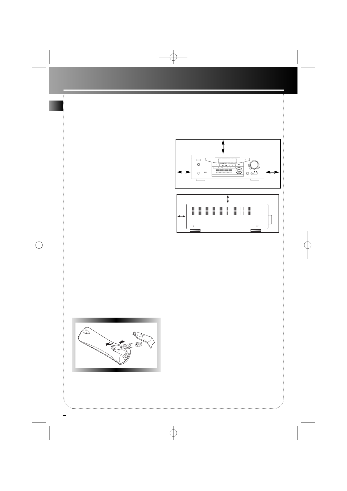
Inserting Batteries into
Remote Control
Insert two AA(R6) batteries according to the + and signs on the battery compartment. To use the remote
control, point it directly at your receiver .
Set up and Maintenance of
the Receiver
• Provide spaces for suf ficient ventilation as indicated:
• Do not connect to the AC power cords until all connections are completed.
• Do not use your set immediately after transferred
from a cold place to a warm place: there is risk of
condensation.
• Do not expose your set to water projections and
excessively high temperatures.
• After having disconnected your set, clean the case
with a soft cloth, or with a slightly humid chamois
leather . Never use strong solvents.
2
Getting Started
EN
10 cm
10 cm10 cm
RT2250 ENG 1/6/00 9:37 AM Page 6
STANDBY
POWER
PHONES
S
T
A
D
I
U
M
I
I
I
I
TUNING
DVD
DSS
HOME THEATRE AUDIO VIDEO RECEIVER
C
O
N
C
E
R
T
T
H
E
A
T
R
E
C
H
U
R
SURR. MODE
6 CH
P.SCAN SPKR IQP.EQ
VCR-1 VCR-2CD
AM/FM AM/FM TV
F
F
O
P
S
D
B
U
L
C
A
N
E
C
R
H
A
TEST TONE
MULTI JOG
5 cm
10 cm
Digital
VOLUME
Sound
Processor
T
H
G
I
N
B
A
S
S
L
E
V
E
L
T
R
E
B
L
E
SET
DEMO
S-VIDEO
VIDEO AUDIOLR
Page 5

3
Getting Started
Connecting to Audio-Visual
Components
This receiver allows you to connect to a large variety
of audio or video components.
Before you Connect
• Protect components from power surges.
• Connect all components before plugging any
power cords into the wall outlet.
• Always turn off the receiver and/or components
before you connect or disconnect any cables.
• Contact consumer relations if you have questions
concerning the connections or components.
Note: Always make sure that color-coded pins match
the color of the terminals in which they are inserted.
The connection cable plugs and jacks are color-coded
as follows:
Speaker T erminals: RT 2250- Red/Black (Main
Speakers), Blue/Black (Center Speaker), Grey/Black
(Rear Speakers) and Brown/Black (subwoofer).
RT2250R - Red/ Black (Main, Center & Rear Speakers)
RCA Phono T ype Terminals: Red for the right (R)
channel. White for the left (L) channel. Yellow for the
video. Black for the powered subwoofer .
Positioning the Cables
Cables should be positioned correctly to avoid audio
hum or interference. Below are a few suggestions:
• Insert all cable plugs into their jacks firmly.
• Place audio/video cables to the sides of the receiver’s back panel instead of straight down the middle
after you have connected the components.
• Try not to coil any power cables and keep them
away from the audio/video cables as much as possible.
• Make sure all antennas and cables are properly
grounded.
Protect your Components from Overheating
• Do not block ventilation holes in any component.
Arrange the components so that air can circulate
freely.
• Do not stack components directly on top of each
other .
• Allow adequate ventilation when placing your
components in a stand.
• Place an amplifier near the top shelf of the stand so
heating air rising from it will not affect other components. If you have a satellite receiver , you should place
it on the top shelf.
EN
RT2250 ENG 1/6/00 9:37 AM Page 7
Page 6
EN
4
Getting Started
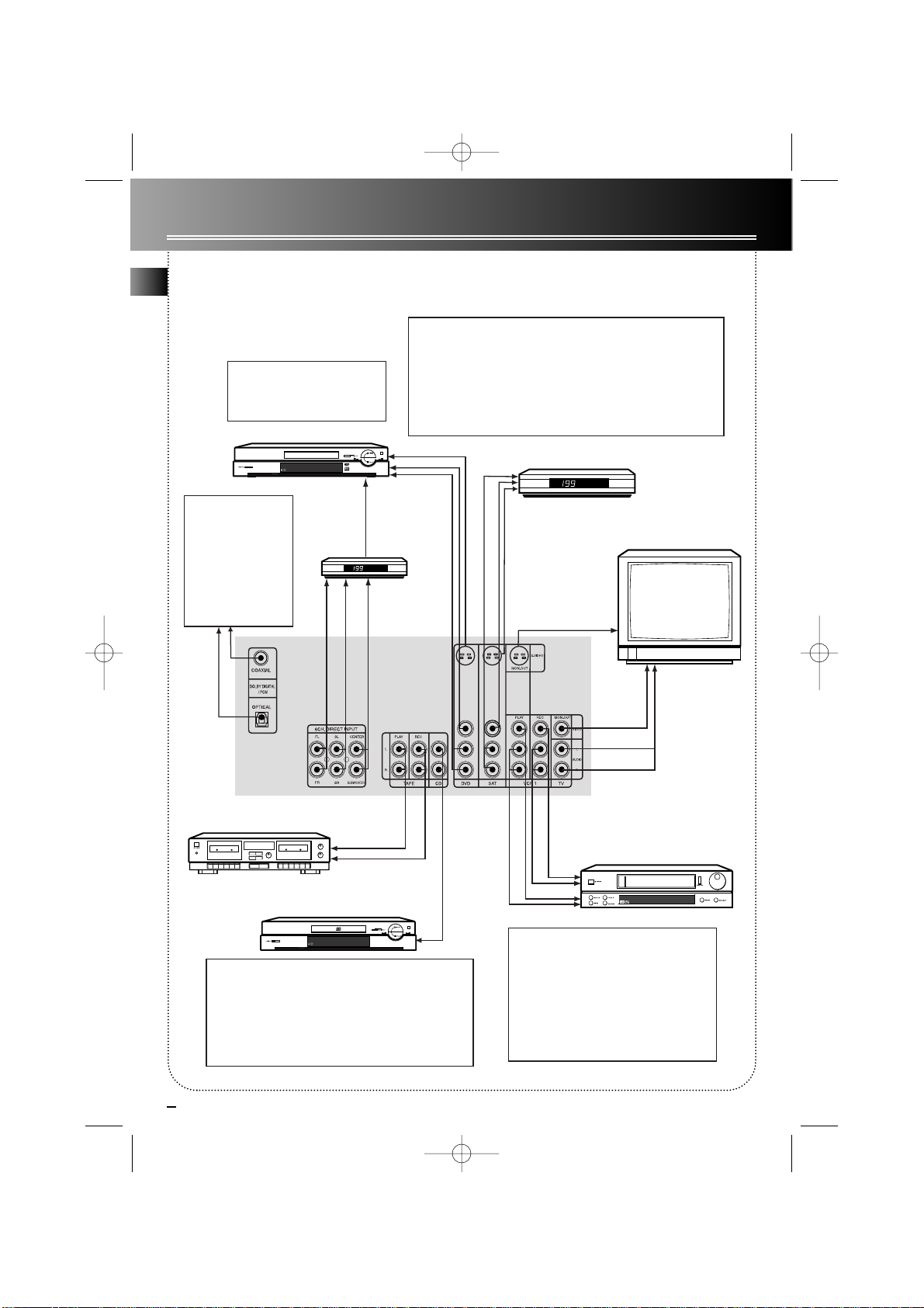
Connecting to Audio-Visual Components
RT2250 ENG 1/6/00 9:37 AM Page 8
Remark: If you have a video
camera, video game machine, or an
extra VCR, connect it to VCR 2 jack
at the front of the receiver
Connect components
capable of outputing
Dolby Digital (e.g. DVD
or SAT) or standard
PCM (CD) format digital
signals. Read section on
"Input Signal Setting"
under "Advanced
Sound Control" carefully
to adjust the matching
input settings.
DVD
e.g. DTS
(Decoder)
to AUDIO OUT
to VIDEO OUT (DVD)
to AUDIO OUT(DVD)
to AUDIO OUT (DVD)
Multi-Channel
Decoder
If you have a SAT receiver or DVD player, you can make use of an optical
digital connecting cord (not supplied) or coaxial digital connecting cord
(not supplied) to enjoy Dolby Digital sound quality. One optical / coaxial
cable is needed for each SAT receiver / DVD player. When optical or
coaxial cable is used, no more analog cable is needed.
Note: This receiver provides one optical and one coaxial digital input for
the connection of your auxillary components. Please connect your
components (e.g. DVD, SAT or CD) to the appropriate digital inputs and
press SET/ DEMO and then rotate MULTI JOG to match your connection.
SAT
to VIDEO OUT (SAT)
to AUDIO OUT (SAT)
TV
to S-VIDEO OUT (SAT)
to S-VIDEO OUT (DVD)
to S-VIDEO IN (TV)
UNIT
BACK PANEL
Tape Deck
to LINE OUT
(Tape Deck)
to LINE IN ( Tape Deck )
to AUDIO OUT (CD)
CD Player
If your CD player is equipped with digital optical jacks, using of
optical cable is preferred. What you need is just one more
optical digital connecting cord(not supplied). Plug it in the digital
input jack of the receiver and you can enjoy better sound quality
brought to you by the optical cable. When optical cable is used,
no more analog cable is needed.
Note: This receiver has one digital optical jack only. Be sure that
such connection does not prevent optical cable connection of
other components (e.g. DVD & SAT)
to VIDEO IN (TV)
to AUDIO OUT (TV)
to AUDIO OUT (VCR)
to VIDEO OUT (VCR)
to AUDIO IN (VCR)
to VIDEO IN (VCR)
If your video component has a S-Video jack
included, you can make use of it to enjoy
enhanced video quality by connecting it to the
relevant S-Video jack at the rear side of the
receiver. One video cable is needed for each
component. When S-Video cable is used, no
more analog video cable is needed.
Note: Before plugging in the optical cable or SVideo cable, make sure to match the shape of the
plug and jack, otherwise, you will not be able to
plug in completely.
VCR
Page 7
5
Getting Started
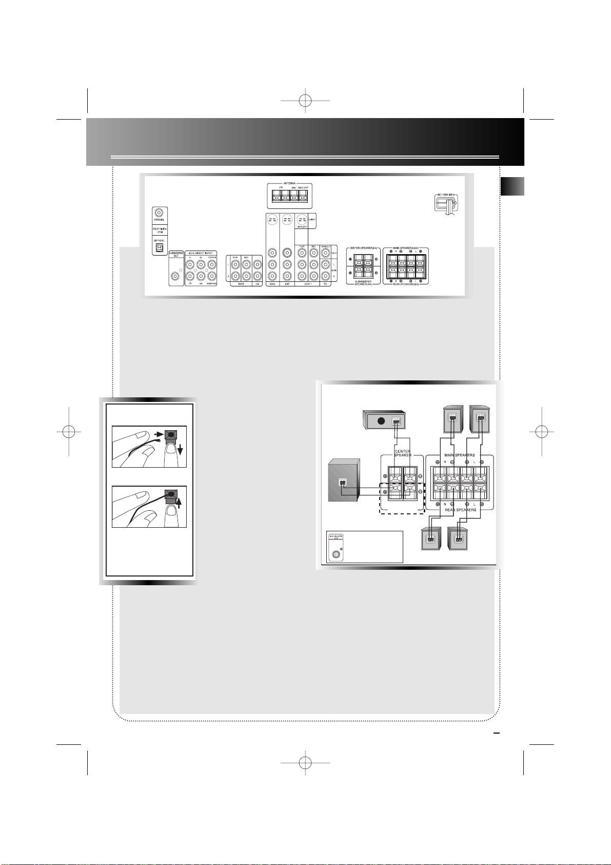
Connecting the Antennas
The AM and FM antennas connect to the AM and
FM terminals on the system’s back panel. They must
be hooked up in order to receive clear reception.
Uncoil the antenna wires and locate the bare ends.
Press down on the tab to open the terminal and
insert the wire. Snap the tab closed. After connect-
ing the antennas, extend
them to their full length
and adjust their positioning
for better reception.
Connecting the
Speakers
At least two front speakers
(left and right) are required.
For better sound quality,
Center speaker , rear speakers and Subwoofer are preferred. Adding center and
rear speakers will enhance
surround effects. Adding a
Subwoofer will increase
bass response.
If you want to enjoy full range of sound effects, with
small speakers, it is a must to use the subwoofer
with the speakers to maintain adequate bass signal
for the surround sound effect.
Speaker cords, 1 for each speaker , are needed for
connection. Twist the stripped ends of speaker cord
about 2/3 inch (15 mm). Press down on the tab to
open the terminal and insert the wire. Snap the tab
closed. To ease speaker connections, the speaker
cords and the terminals are color-coded into:
Red/Black (Main Speakers), Blue/Black (Center
Speaker) and Grey/ Black (Rear Speakers). When connecting the speakers, make sure the colors of speaker wires and terminals are matched. If the cords are
reversed, the sound will be distorted and will lack
bass.
Connecting the Subwoofer
For RT2250, connect the subwoofer with the audio
cord (brown/ black) provided. For RT2250R, or if you
want to connect your own powered subwoofer , a
monoaural audio cord (not supplied) is needed.
This receiver offers a high flexibility for user to use a
large variety of speakers and subwoofers. For more
information please refer to section “Fine Setting of
the Speakers” in “Advanced Sound Control” on
page 12.
EN
RT2250 ENG 1/6/00 9:37 AM Page 9
Antenna and Speaker
Wire Connection
Push Speaker terminal tab
down to insert wire.
Release tab to lock wire in
the terminal.
NOTE: Make sure the insulation
is completely removed from the
ends of the Antenna and
speaker wires at all connection
points.
CENTER
SPEAKER
-
+
SUB WOOFER
-
+
SUB WOOFER
SPEAKER
This part not
available for RT2250R
Use this jack on the left back
panel for connecting powered
sub- woofer.
SURROUND SOUND SPEAKERS
RIGHT
-
+
MAIN SPEAKERS
RIGHT
-
+
LEFT
-
+
LEFT
-
+
Page 8

EN
6
Positioning your Speakers
Y our system is equipped with Dolby Digital, which
enables the unit to reproduce sound effects as they
were intended. However , the speakers must be properly positioned and balanced.
In order to enjoy Dolby-enhanced sound quality, five
speakers are preferred: One center speaker , left and
right main speakers, rear left and right speakers, and
an optional subwoofer . However, if your front
speakers are small speakers, then a subwoofer is
essential or you will not be able to enjoy enhanced
bass effects. Below are a few suggestions for the set
up:
1. The two main speakers should be set between six
and ten feet apart. Putting them any closer or farther
apart may result in less satisfactory sound.
2. Try to align center speaker and two main speakers,
or set the center speaker slightly behind the left and
right main speakers, otherwise the surround effect
may be less satisfactory.
3. Aim the rear speakers directly at the two main
speakers, matching height to height. If the room is
sparsely decorated, slightly tilt the speakers down to
increase sound quality. If the room is densely
decorated, face the speakers towards the rear wall at
the ceiling.
Actually there are many more possible options. Y ou
may experiment repeatedly to find a right balance
for you.
For more information on speaker setup, please refer
to “Fine Setting of the Speakers” on page 12 &
“Speaker Distance” on page 13
Getting Started
Dolby Digital
Manufactured
under license from
Dolby Laboratories.
“Dolby”, “Pro Logic” and the double-D symbol
are trademarks of Dolby Laboratories.
Copyright 1992-1997 Dolby Laboratories, Inc.
All Rights Reserved.
RT2250 ENG 1/6/00 9:37 AM Page 10
Main
Left
Rear
Left
Centro
TV
Main
Right
Rear
Rigth
Subwoofer
Optional
Page 9

7
Getting Started
EN
Using Headphones
To listen privately through your audio system, use the PHONESjack on the
receiver . However, make sure you turn down the volume before you put on
the headphones. Increase the volume to the desired level after headphones
are in place.
Once headphones are connected, “HEADPHONE DOWNMIX 2
CHANNEL” will scroll on display.
Demo Mode
Right after you have plugged in the power , a demo message will appear in display. It will also be displayed if
you press the SET/DEMO at STANDBY mode or press a source button ( like CD) but then leave all buttons
untouched for 30 seconds. To restore to normal status, press SET/DEMOagain to return to STANDBY mode.
Connecting for Power
Make sure you connect all your other electronic components and the
speakers before plugging your receiver into the outlet. Plug the power cord
in the wall outlet, matching the wide blade of the plug with the wide slot
in the outlet. Be sure to insert the plug completely.
Restore to Factory Settings
Y ou can always restore all settings back to original state. When the receiver is in ST ANDBY mode, press accordingly as:
STADIUM NIGHT DSP OFF CLUB
then you can restore everything like preset radio station frequencies, speaker settings,etc, back to the first
time you use it.
Note: As you turn on the receiver , it will first enter TUNER mode and show frequency as 87.5MHz after the
settings have been restored.
RT2250 ENG 1/6/00 9:37 AM Page 11
Page 10

8
EN
Receiver Controls
1. STANDBY
To turn the unit on/ off. When the
system is turned on, the unit will go
to the mode it was in before power
off.
2. MUTE
To mute all audio outputs.
3. PHONES
Plug your headphones (not supplied)
into it for your private enjoyment.
Speakers will be off when phones are
inserted.
4. Source Buttons
To select sound source. For example,
CD, SAT etc. In standby mode, they
are also One Touch Power Onkeys to
turn on the receiver directly at the
source mode you want.
5. Display
To display current status of the receiver .
6. Sound Control
Let you adjust the sound – volume,
treble, bass & balance. To change the
VOLUME, turn the large central
knob. To adjust TREBLE orBASS,
press relevant button and turn the
knob. To change the volume of individual speaker, press LEVEL button
repeatedly to select the speaker, then
turn the knob to adjust the level. (
refer to “The TEST/ SET UP button”
on page 12.)
7.DSP (Digital Sound Processor) &
NIGHT mode
Press corresponding button to select
the mode (STADIUM/ CONCERT/
THEATER/ ARENA/ CHURCH/ CLUB/
OFF) you want. Press NIGHT for your
enjoyment at night (see page 12).
8. MUL TI JOG, SET/DEMO
When pressing the SET/DEMO
repeatedly, the display will toggle
among Audio Source (for DVD, SAT &
CD), SLEEP mode and DIM selection.
Please refer to page 12 for Input
Signal Setting. In SLEEP mode, you
can set the receiver to turn off after
30, 60, 90 or 120 minutes. In DIM
selection, you can rotate to set the
brightness of the display. Such setting
will be stored. Also use the MULTI
JOG for speakers and sub-woofers
setup and preset radio stations selection.
9. TUNING
Press to select the tuner frequencies
manually.
10. P . SCAN (Pr eset Scan)
Press for about 2 seconds and tuner
station presets will be started automatically.
11. SURR. MODE
Press repeatedly to select the surround mode you want. ( refer to
“Advanced Sound Control” on page
11.)
12. 6 CH (6 Channels)
Press to select the input connected to
an external 6-Channel decoder. Press
again to return to the most recently
selected source mode. (see “5.1 ch
Input for Dobly Digital” on page 11).
13. TEST/ SET UP
When pressing it briefly, a short noise
(test tone) will be generated in the
speakers one by one so that you can
adjust the volume of individual
speaker. When keep pressing for two
seconds, it will enter setup mode for
speakers and subwoofers. Rotate the
MUL TI JOG to choose the options.
(refer to “The TEST/ SET UP button”
on page 12.)
14. PRESET EQ
Press repeatedly to select the desirable EQ mode (music style) – CLAS-
SIC, POP, ROCK, JAZZ, VOCAL or
FLAT. Your choice will be saved auto-
matically.
15. BYPASS
Press to cut sound output from center , surround & subwoofer speakers.
16. VCR2
For convenient use of your digital
camera, family game machines,
second VCR, etc.
Note: If your video component has
S-Video output, you can enjoy
enhanced video quality by connecting it to the S-Video jack on receiver
using a S-Video cable (not included
).
1
2
3
4
67
129 11
Operating your Receiver
10
5
13 14
15
8
16
RT2250 ENG 1/6/00 9:37 AM Page 12
STANDBY
MUTE
PHONES
S
T
A
D
I
U
M
C
O
N
C
E
R
T
I
I
I
I
P.SCAN BYPASS
TUNING
DVD
CD
HOME THEATER AUDIO VIDEO RECEIVER
T
H
E
A
T
E
R
C
H
U
R
E
C
R
A
H
TEST/ SET UP
SURR. MODE
6 CH
VCR-1 VCR-2SAT
FM/ AM TV TAPE
B
U
L
C
A
N
PRESET EQ
MULTI JOG
D
igital
S
ound
P
rocessor
T
H
G
I
N
F
F
O
P
S
D
SET
DEMO
S-VIDEO
VOLUME
B
A
S
S
T
R
E
B
L
E
VCR 2
VIDEO AUDIOLR
L
E
V
E
L
Page 11

9
1. ON/OFF
To turn on or of f the receiver and
other auxillary components (see
page 10 “Using the Remote to
Control Additional Components”).
2. Source Buttons
To turn on and select various
audio/ video sources. Y ou can also
enter the 6 Channels direct input
mode by pressing DVD•6CH.
3. CH+, CH- (Channel Buttons)
To select programmed stations (in
TUNER mode).
4. VOL (Volume Buttons)
To adjust the volume.
5. MUTE
To mute all audio outputs.
6. Adjustment Buttons
Press AUDIO button to activate
the control, then upon pressing
OK, the display will toggle among
Preset EQ (Stereo only), SLEEP
Mode & DIM Mode. When the
display shows the setup you want
to change, press the left and right
arrow buttons beside OK button
to make changes, then press OK to
finalize your choice.
7. Number Buttons
To access directly a pre-set station
(in TUNER mode).
8. MENU
Press to store desired frequency in
memory. The flashing word MEM-
ORY in red will appear in display.
Input your desired channel num-
ber while the word is still flashing
and the frequency will be stored.
(For details, refer to "Storing and
Recalling Stations in Memory" on
page 10.)
9. Operation Buttons
In TUNER mode, you can press
REVERSE and FORWARD keys to
tune down or up the radio frequency. PLAY, RECORD, STOP
and PAUSE keys are for easy con-
trol of components (like CD, TV ,
DVD, TAPE, etc.) other than the
receiver itself. What you need is to
encode the components in
advance. (For details, refer to
"Using the Remote to Control
AdditionalCcomponents" on page
10.)
10. DIGITAL
Select the way your audio/video
components are connected to the
receiver – Analog, Optical, or
Coaxial.
11. LEVEL
Press to adjust the volume of individual speaker . Press repeatedly
and the display will toggle among
different channels (Left main
speaker , Right main speaker,
Center speaker , Left surround
speaker , Right surround speaker,
and/or Subwoofer , if available),
then press the left and right
arrow buttons beside OK button
for adjustment.
12. SURR (Surround Sound
Control)
Press to change the surround
sound settings. The display will
toggle among DOLBY DIGITAL,
DOLBY PRO LOGIC, DOLBY 3
STEREO, STEREO and DSP modes.
(For details, refer to section
"Advanced Sound Control" on
page 11.)
Note: The remote buttons GO
BACK•DISK, GUIDE•RDM•PTY ,
INFO•RDS, CLEAR, INPUT•SEEK
& ANT•FMS do not work with the
receiver .
Operating your Receiver
Your Remote Control
Please be sure you have inserted the batteries into the remote control (see
relevant section on page 3.) Y ou can test it by pressing any button. If it
works, the red LED will light.
1
2
3
4
5
6
7
9
8
10 11 12
EN
6
RT2250 ENG 1/6/00 9:37 AM Page 13
TV
ON OFF
VCR1
AM•FM
VCR2
P
T
Y
2
5
8
0
SAT•CABLE
TAPECD
+
H
C
C
H
-
G
O
INFO•RDS
OK
CLEAR
3
6
9
ANT•FMS
PLAY FORWARDREVERSE
STOP PAUSE
LEVELAUDIO
SURRDIGITAL
V
O
L
K
S
I
D
•
K
C
A
B
DVD•6 CH
L
O
V
MUTE
M
D
R
•
E
D
I
U
G
MENU
1
4
7
INPUT•SEEK
RECORD
•
universal
Page 12

10
EN
The Built-in
Radio
The receiver has
built-in AM/FM
radio function.
Y ou can simply
connect it to
power and speakers to listen to your favorite radio stations.
1. Select TUNER.
2. Tune to your favorite station.
3. Adjust volume.
4. Set preset EQ if needed
5. Set surround mode if needed.
Seek Tuning
Y ou can keep pressing one of the
TUNING buttons on the unit or REVERSE/
FORWARD buttons on the remote for a
second, and the receiver will search for
the next available station for you.
Storing and
Recalling
Stations in
Memory
Set to desired frequency by the
receiver or remote
control , then press MENU on the
remote control. The flashing word
MEMORY in red will appear in display.
While the word MEMORY is still flashing, input your desired channel number
and the frequency will be stored.
Tip: You can store up to 30 stations.
After you have done so, you can rotate
the MUL TI JOG on receiver or press CH+
or CH- buttons on remote to select the
preset stations directly.
Note: The CH+ and CH- buttons
respond only in TUNER mode in case
you want to switch channels.
1
3
2 5 4
1
2
4
3
5
Operating your Receiver
Using the Receiver to Play DVD or
CD or Video Cassette Player
After you have connected your DVD or CD or VCR
player with the receiver , you can partly control them
through your receiver:
1. Connect the DVD or CD or VCR player with the
receiver . (For details, refer to page 4.)
2. Select DVD or CD or VCR according to the source
connected.
3. Turn on the connected player and start playback.
4. Set Preset EQ if needed. (For details, refer to item
11 “Preset EQ” on page 8.)
5. Set Surround Mode if needed. (For details, refer to
“Advanced Sound Control” on page 12)
6. Set Night Mode if needed. (For details, refer to
“Night Mode” on page 12.)
7. Adjust Volume.
Using the Remote to Control
Additional Components
Y ou can set your remote to control other components
(like CD, TV , DVD, T APE, etc.). What you need is to
encode them in advance (not necessary for recent
RCA & Proscan models)
1. Turn on the component to be programmed.
2. Look up the brand and corresponding code number in the code list from page 15 to17.
3. While keeping the corresponding Source Button
(like VCR1, VCR2, TV, DVD) on the remote pressed,
enter the code from the code list through the
Number Buttons.
4. Release the component button, then press
ON•OFF to see if the component will be turned off.
5. If this does not work, repeat steps 3 and 4 by trying
to use the next code (if available) listed for the brand
of your component until the component responds to
RT2250 ENG 1/6/00 9:37 AM Page 14
STANDBY
MUTE
PHONES
S
T
A
D
I
U
M
C
O
N
C
E
R
I
I
I
I
TUNING
P.SCAN BYPASS
DVD
CD
HOME THEATER AUDIO VIDEO RECEIVER
T
T
H
E
A
T
E
R
C
H
U
R
C
H
SURR. MODE
6 CH
VCR-1 VCR-2SAT
FM/ AM TV TAPE
T
H
G
I
N
F
F
O
P
S
D
B
U
L
C
A
N
E
R
A
TEST/ SET UP
PRESET EQ
SET
DEMO
MULTI JOG
TV
ON OFF
VCR1
AM•FM
VCR2
SAT•CABLE
DVD•6 CH
TAPECD
+
H
C
V
O
L
L
O
V
1
4
7
INPUT•SEEK
C
H
MUTE
M
•
D
P
T
R
•
Y
E
D
I
U
G
OK
MENU
2
5
8
0
PLAY FORWARDREVERSE
STOP PAUSE
RECORD
LEVELAUDIO
universal
K
S
I
D
-
•
G
K
O
C
A
B
INFO•RDS
CLEAR
3
6
9
ANT•FMS
SURRDIGITAL
Digital
VOLUME
Sound
Processor
B
A
S
S
L
E
V
E
L
T
R
E
B
L
E
VCR 2
S-VIDEO
VIDEO AUDIOLR
Page 13

11
Operating your Receiver
EN
the remote command.
Note: Once your component is encoded, you can
press ON/OFF on the remote once to turn off the
component and then followed by the second time
quickly to turn off the receiver (i.e. this unit). If you
only want the receiver to be turned off, select FM/
AM while the unit is ON before pressing ON/OFF.
Tips:
This remote may not operate all models of the brands shown.
If batteries are removed from the battery compartment of
the remote control, all memory will be lost. You need to reenter all previously programmed codes again.
The buttons on the remote may not work correspondingly
with those on the components brands. Experiment with the
remote and your components to see which buttons work. If
only a few functions operate, check to see if another code
set will work with more buttons.
Advanced Sound Control
Sound Enhancement Systems
This receiver is equipped with several built-in sound
enhancement systems to give you the sound quality
you have once dreamed of – but now comes true:
Dolby Pro Logic and Dolby 3 Stereo
This surround system reproduces theater-like surround
sound from Dolby-encoded software. The Pro Logic
mode uses the built-in circuit to steer the Left, Center ,
Right and Surround channel audio signals and uses all
five speakers and an optional subwoofer to play
decoded Dolby Pro Logic program source, such as TV
and VCR. The 3 Stereo mode will redirect the
Surround signals to the front left and right speakers
when only the front and center speakers are used.
Use this mode to suit your speaker system configurations (such as size and number of speakers) and type
of program (such as VCR).
5.1 ch Input for Dolby Digital
The Dolby Digital mode lets you enjoy full digital
surround from software processed in the Dolby Digital
format. Dolby Digital provides better sound quality
and more powerful presence than conventional Dolby
Surround.
When the soundtrack of a Dolby Digital movie was
made, all the sound effects are mixed down to six sep-
arate channels of digital audio, and these six channels
of independent digital audio are pressed to a single
stream of digital data on your DVD. When you play it
by your DVD player , the receiver decodes this stream
of digital data back to six audio channels for playback.
Dolby Digital is optimal for DVD and SAT.
This unit is equipped with Dolby Digital 5.1-channel
input terminal so that you can enjoy enhanced full
digital surround sound. Being different from Dolby
Pro Logic in which only four channels ( Front Left,
Front Right, Centre and Rear ) are used, the new system provides stereo separation of the rear speakers
(Rear-Right, Rear-Left ). These 5 channels, together
with the subwoofer channel for bass sounds ( counted
as 0.1 channel ), constitue as 5.1-Channel ( or 6
Channels ) Input for Dolby Digital that brings you the
most sophisicated sound enjoyment.
Press 6 CH on the unit or DVD•6 CH button on the
remote to select the input connected to an external 6channel decoder . Press again return to the most
recently selected mode.Y ou can only adjust Sound
Control, SLEEP mode, DIM selection, Source Buttons
and MUTE when this mode is selected.
Stereo
The Stereo mode uses the two main channel outputs
from the front speakers. Use this mode if you have
connected the front speakers only.
RT2250 ENG 1/6/00 9:37 AM Page 15
Page 14

12
Advanced Sound Control
EN
DSP (Digital Sound Processor)
These digital sound effects resemble sounds in a real
environment such as Stadium, Concert, Theater ,
Arena, Church, Club. DSP automatically converts analog audio signals to digital ones which enables you to
adjust the sound without degrading the sound quality. Dif ferent modes will give you different feel of size
and type of listening environment.
Night Mode
By using Dynamic Range Compression technology,
you can enjoy enhanced sound quality by Dolby
Digital at night without interrupting your roommates
or neighbors. While enjoying a Dolby Digital enabled
component (DVD, SAT), you can activate Night Mode
by pressing NIGHT button at the front of the receiver,
and this mode will compress the difference in volume
between normal voices and sounds like explosions.
There are two modes (SOFT, SOFTER) for you to
choose the extents of compression.
Fine Setting of the Components
Input IQ
One of the smartest features of the receiver is the
ability to pre-select the best surround mode for you
once you turn on the unit by pressing the Source
Buttons (like DVD, SAT, CD) directly. The default surround modes for different components are as table
below. If you decide to change the surround mode,
you can press the SURR MODE button to change to
the mode you want.
Input Signal Setting
The receiver has defaulted to the most convenient
settings for your easiest use (see table).
If your connection is different from the default setting, you can press SET/DEMO and then rotate MULTI
JOG to toggle among optical/ coaxial/ analog to
match your connection. Y our selection will be stored
automatically.
Every time you press the source button, the input setting (e.g. DVD/ OPTI) will be shown on display for a
few seconds to refresh your memory.
Fine Setting of the Speakers
This receiver supports a wide range of speakers and
subwoofers. For optimal surround sound enjoyment,
you need to register the speaker selection settings of
your audio system. If you buy this receiver with
accompanied speaker package, then this step has
been done for you.
Also, to make the surround sound more effective and
suit the acoustic conditions in your listening room,
you need to delay the signal from some of the speakers. Such channel delay compensates for center or
surround speakers that are closer to listening position
than the front speakers. Y ou can make use of the
TEST/ SET UP button to control the speakers such as
their relative loudness.
The TEST/ SET UP button
Y ou can adjust the relative loudness of the individual
speakers by TEST/ SET UP button. In Dolby modes,
press the button briefly. A short noise will be heard in
the speakers one by one. The speaker having the
noise at that moment will be shown in the display.
Y ou can listen to that speaker and rotate the MULTI
JOG to adjust the level.
Speaker Configurations
Y ou can also change the setup of the speakers by
pressing the TEST/ SET UP button until the display
shows L/R LRG which enables you to set the volume
size of the front speaker .
Source/ If Digital Input (optical If Analog Input
Input or coaxial) is selected is selected
DVD Dolby Digital PRO LOGIC
SAT Dolby Digital PRO LOGIC
VCR1 N/A PRO LOGIC
VCR2 N/A PRO LOGIC
TV N/A PRO LOGIC
CD STEREO STEREO
TAPE N/A STEREO
TUNER N/A STEREO
DEFAULT INPUT (as seen on display)
Coaxial (SAT/ COAX)
Optical (DVD/ OPTI)
Optical (CD/ OPTI)
Analog (VCR1/ ANL)
Analog (VCR2/ ANL)
Built-in Tuner
Analog (TAPE/ ANL)
SOURCE
SAT
DVD
CD
VCR1
VCR2
FM/AM
TAPE
RT2250 ENG 1/6/00 9:37 AM Page 16
Page 15

13
Advanced Sound Control
EN
By pressing the button repeatedly while display is still
showingL/R LRG, the display will toggle among: front,
center , surround, subwoofer, subwoofer phase and
speakers’ distance setup. Y ou can now set the volume
size or speakers’ distance by rotating the MUL TI
JOG.
Note:
• The sub-woofer selection will always be YES when
the main speakers are set to small (SML).
• For the subwoofer phase setting, it will be affected
by how you locate the subwoofer . Try both + and settings and select the one that has better bass effect.
Speaker Distance
To make the surround sound more ef fective and suit
the acoustic conditions in your listening room, you
need to input the distance of the speakers measured
from your favourite listening position. The receiver
will adjust the appropriate delay compensation for
you.
Note: The receiver has defaulted the following distances:
Main speakers (L/R) 15 ft
Center speaker (Cch) 15 ft
Rear speaker (SUR) 10 ft
Speaker Icons
The receiver shows you the speakers’ types and settings on the display with the following icons:
Displaying Program Formats
When a digital source is playing, the receiver will
automatically switch to the proper surround mode
and indicates on the speaker icons on the right-hand
side of the display. (See diagram)
It is important to note, however ,
that not all Dolby Digital sources are
encoded with the full complement
of five channels plus LFE*. Speaker
icons show how many and which
speaker you have enabled (See “Fine
Setting of the Speakers”) and the
letters inside the speaker icons show which channel is
present in the source information. For example, the
diagram shown means you have all the five speakers
and subwoofer enabled and the digital sources you
played have five channels plus LFE complemented.
* LFE stands for Low Frequency Effect. The indication “LFE” appears
if the digital source contains LFE information. In this case, the bass
signal will be delivered to the subwoofer, offering more dynamic deep
bass sound effects. If the letter is flashing, the signal is either too
weak or just gone.
Front Speaker selection Large/ Small
Center Speaker selection Large/ Small/ None
Surround Speaker selection Large/ Small/ None
Subwoofer selection Yes/ No
Subwoofer Phase + / Front Speaker distance 0-40 ft
Centre Speaker distance 0-40 ft
Rear Speaker distance 0-40 ft
RT2250 ENG 1/6/00 9:37 AM Page 17
Small Main Speakers
Main
Left
L/R
SUR
Rear
Left
Centre
Main
Right
C ch
L/R
SUR
Rear
Right
Large Main Speakers
Small Center Speakers
Large Center Speakers
Small Rear Speakers
Large Rear Speakers
Subwoofer Present
Page 16

14
EN
Care and Maintenance
Troubleshooting Tips
Receiver/Tuner Operation
STEREO indicator is off.
• Adjust the antenna.
The signal is Mono. Severe hum or noise.
• The signal is too weak. Connect an external antenna.
Remote Control Operation
The remote control does not operate the unit.
• Another function mode is selected on the remote.
Press the correct Source Button.
• No batteries installed. (included with your system)
Install the batteries before attempting to operate the
remote. Be sure to match the + and - ends of each
battery to the symbols shown in the remote battery
compartment.
• The batteries are weak. Replace all batteries.
• The remote is not pointed at the remote control
sensor on the main unit or there is an obstacle
between the remote and the main unit.
• The remote control is too far from the main unit,
move closer .
General
No audio.
• Make sure the speakers are connected.
• Check the connections.
• Check the power cord connections.
• Make sure the MUTE indicator on the front panel
is off.
• Make sure the digital setting (optical, coaxial or
analog) is correct.
No audio from one channel.
• Check the speaker level setting.
• Check the speaker wire or cable connections.
Noise creates when the TV is turned on.
• The TV is too close to the audio system.
Specific instruments sound displaced.
• Check the connections between the receiver and
the speakers if the sound does not match the video.
• Press the Source Button for the video source.
Cleaning the Exterior
• Disconnect the system from AC power before
cleaning the exterior of the system with a soft dust
cloth, or with a slightly humid chamois leather . Never
use strong solvents.
Equipment Specifications:
AMPLIFIER SECTION:
All 5 channels: each 50W at 6 ohm.
0.9% THD @1 kHz
Subwoofer channel: 100w at 3 ohm (RT2250 only)
Muting Attenuation: 65dB
Frequency Response: 40Hz to 20kHz +/-3dB
Signal to Noise Ratio: 65dB (Bypass mode)
VIDEO SECTION:
Input ( Sensitivity/ Impedance ):1Vp-p/ 75ohm
Output (Level/ Impedance): 1Vp-p/ 75 ohm
Frequency Response: 10Hz to 6MHz at +/- 3dB
Signal to noise ratio: 40dB
Crosstalk @3.58MHz: 40dB
AM TUNER SECTION:
Frequency Response: 80Hz – 2kHz +/-6dB
Usable Sensitivity: 800uV/m @ S/N 20dB
Signal to Noise: 38dB
Image Ratio: 27dB @ 1000kHz
IF Rejection: 35dB
FM TUNER SECTION:
Frequency Response: 40Hz – 15kHz +/-3dB
Quieting: 24dBu
Signal to Noise: 60dB(stereo)/ 65dB(mono)
Image Ratio: 40dB
IF Rejection: 50dB
RT2250 ENG 1/6/00 9:37 AM Page 18
Page 17

EN
15
Remote Codes
CABLE CODES
ABC 5002, 5003, 5004, 5005, 5006, 5009, 5053
ANTRONIX 5008, 5009
ARCHER 5008, 5009, 5010, 5011
CABLETENNA 5008
CABLEVIEW 5008
CENTURY 5011
CITIZEN 5011
COLOUR VOICE 5012, 5013
COMTRONICS 5014, 5015
CONTEC 5016
EASTERN 5017
GARRARD 5011
GC ELECTRONICS 5009
GEMINI 5018, 5019, 5049
GENERAL INSTRUMENT 5003
HAMLIN 5020, 5021, 5022, 5035, 5045
HITACHI 5003
HYTEX 5002
JASCO 5011
JERROLD 5003, 5005, 5007, 5018, 5023,
5024, 5046, 5053
MAGNAVOX 5025
MEMOREX 5026
MOVIE TIME 5002, 5027, 5028
NSC 5002, 5027, 5028
OAK 5002, 5016, 5029
PANASONIC 5048, 5052
PARAGON 5026
PHILIPS 5011, 5012, 5013, 5019, 5025,
5030, 5031, 5032
PIONEER 5033, 5034
PULSAR 5026
RCA 5047, 5049, 5052
REALISTIC 5009, 5049
REGAL 5022, 5035
REGENCY 5017
REMBRANDT 5003
RUNCO 5026
SAMSUNG 5014, 5034
SCIENTIFIC ATLANTA 5006, 5036, 5037, 5038
SIGNAL 5014, 5018
SIGNATURE 5003
SL MARX 5014
SPRUCER 5052
STARCOM 5007, 5018, 5053
STARGATE 5014, 5018
STARQUEST 5018
TANDY 5040
TELEVIEW 5014
TOCOM 5004, 5023, 5041
TOSHIBA 5026
TUSA 5018
TV86 5027
UNIKA 5008, 5009, 5011
UNITED ARTISTS 5002
UNITED CABLE 5053
UNIVERSAL 5008, 5009, 5010, 5011
VIDEOWAY 5044
VIEWSTAR 5015, 5025, 5027, 5040
ZENITH 5026, 5050, 5051
VCR CODES
ADMIRAL 2131
ADVENTURA 2026
AIKO 2027
AIWA 2002, 2026
AKAI 2003, 2004, 2005, 2007, 2008, 2111, 2112, 2113
AMERICAN HIGH 2021
ASHA 2013
AUDIO DYNAMICS 2009, 2010
AUDIOVOX 2014
BELL & HOWELL 2011
BEAUMARK 2013
BROKSONIC 2012, 2025
CALIX 2014
CANDLE 2013, 2014, 2015, 2016, 2017,
2018, 2019
CANON 2021, 2022, 2114
CAPEHART 2020, 2110
CARVER 2062
CCE 2027, 2061
CITIZEN 2013, 2014, 2015, 2016, 2017,
2018, 2019, 2027
COLORTYME 2009
COLT 2061
CRAIG 2013, 2014, 2023, 2061
CURTIS-MATHES 2000, 2002, 2009, 2013, 2016,
2018, 2021, 2022, 2024, 2115
CYBERNEX 2013
DAEWOO 2015, 2017, 2019, 2025, 2026,
2027, 2028, 2110
DAYTRON 2110
DBX 2009, 2010
DIMENSIA 2000
DYNATECH 2002, 2026
ELECTROHOME 2014, 2029
ELECTROPHONIC 2014
EMERSON 2002, 2012, 2014, 2015, 2021, 2024, 2025, 2026,
2029, 2030, 2032, 2033, 2034, 2035, 2036, 2037,
2038, 2039, 2040, 2041, 2042, 2044, 2045, 2047,
2065, 2105, 2113, 2116, 2117, 2130
FISHER 2011, 2023, 2048, 2049, 2050, 2051, 2052, 2118
FUJI 2021, 2119
FUNAI 2002, 2026
GARRARD 2026
GE 2000, 2001, 2013, 2021, 2022, 2053, 2115, 2120
GOLDSTAR 2009, 2014, 2018, 2054, 2121
GRADIENTE 2026
HARLEY DAVIDSON 2026
HARMAN KARDON 2009
HARWOOD 2061
HEADQUARTER 2011
HITACHI 2002, 2055, 2056, 2057, 2107,
2111, 2120, 2122
HI-Q 2023
INSTANT REPLAY 2021
JCI 2021
JC PENNEY 2009, 2010, 2011, 2013, 2014,
2021, 2022, 2055, 2056, 2058,
2059, 2060, 2107, 2118
JENSEN 2055, 2056, 2111
JVC 2009, 2010, 2011, 2018, 2058,
2111, 2123
KENWOOD 2009, 2010, 2011, 2016, 2018,
2058, 2111, 2123
KLH 2061
KODAK 2014, 2021
LLOYD 2002, 2026
LOGIK 2061
LXI 2014
MAGNAVOX 2021, 2022, 2062, 2063, 2104,
2108, 2124
MAGNIN 2013
MARANTZ 2009, 2010, 2011, 2016, 2018,
2021, 2058, 2062, 2064
MARTA 2014
MASUSHITA 2021
MEI 2021
RT2250 ENG 1/6/00 9:37 AM Page 19
Page 18

EN
16
MEMOREX 2002, 2011, 2013, 2014, 2021, 2023, 2026,
2104, 2131
MGA 2029, 2065, 2113
MGN TECHNOLOGY 2013
MIDLAND 2053
MINOLTA 2055, 2056, 2107
MITSUBISHI 2029, 2055, 2056, 2065, 2066, 2067, 2069,
2070, 2071, 2072, 2073, 2074, 2106, 2113,
2123
MONTGOMERY WARD 2075, 2131
MOTOROLA 2021, 2131
MTC 2002, 2013, 2026
MULTITECH 2002, 2013, 2016, 2026, 2053, 2061
NEC 2009, 2010, 2011, 2016, 2018, 2058, 2064,
2076, 2078, 2079, 2111, 2123
NIKKO 2014
NOBLEX 2013
OLYMPUS 2021
OPTIMUS 2014, 2131
OPTONICA 2096
ORION 2035
PANASONIC 2021, 2022, 2109, 2125, 2126, 2127
PENTAX 2016, 2055, 2056, 2107, 2120
PENTEX RESEARCH 2018
PHILCO 2021, 2022, 2062, 2063
PHILIPS 2021, 2062, 2096, 2124
PILOT 2014
PIONEER 2010, 2055, 2080, 2081, 2123
PORTLAND 2016, 2017, 2019, 2110
PROSCAN 2000, 2001
PROTEC 2061
PULSAR 2104
QUARTER 2011
QUARTZ 2011
QUASAR 2021, 2022, 2125
RCA 2000, 2001, 2003, 2013, 2021, 2055, 2056,
2082, 2083, 2084, 2085, 2086, 2087, 2088,
2089, 2090, 2091, 2107, 2115, 2120, 2125
RADIOSHACK/REALISTIC 2002, 2011, 2013, 2014, 2021, 2022, 2023,
2026, 2029, 2049, 2050, 2096, 2131
RADIX 2014
RANDEX 2014
RICOH 2128
RUNCO 2104
SAMSUNG 2005, 2013, 2015, 2033, 2053, 2112
SANKY 2104, 2131
SANSUI 2010, 2092, 2111, 2123
SANYO 2011, 2013, 2023
SCOTT 2012, 2015, 2025, 2032, 2035, 2038, 2065,
2093, 2116
SEARS 2011, 2014, 2021, 2023, 2048, 2049, 2050,
2051, 2055, 2056, 2107, 2118
SHARP 2002, 2017, 2029, 2094, 2095, 2096, 2131
SHINTOM 2004, 2056, 2061, 2098
SHOGUN 2013
SIGNATURE 2002, 2131
SINGER 2021, 2061, 2128
SONY 2002, 2004, 2098, 2099, 2119, 2128
STS 2021, 2107
SYLVANIA 2002, 2021, 2022, 2026, 2062, 2063, 2065,
2124
SYMPHONIC 2002, 2026
TANDY 2002, 2011
TASHIKO 2014
TATUNG 2058, 2111
TEAC 2002, 2026, 2058, 2085, 2111
TECHNICS 2021, 2109
TEKNIKA 2002, 2014, 2021, 2026, 2100, 2129
TMK 2013, 2024, 2047
TOSHIBA 2015, 2049, 2051, 2055, 2065, 2093, 2116
TOTEVSION 2013, 2014
UNITECH 2013
VECTOR RESEARCH 2009, 2010, 2015, 2016
VICTOR 2010
VIDEO CONCEPTS 2009, 2010, 2015, 2016, 2113
VIDEOSONIC 2013
WARDS 2002, 2013, 2014, 2015, 2021, 2023, 2026,
2029, 2055, 2056, 2061, 2096, 2101, 2102,
2103, 2107, 2116, 2131
XR-1000 2021, 2026, 2061
YAMAHA 2009, 2010, 2011, 2018, 2058, 2111
ZENITH 2004, 2098, 2104, 2119, 2128
TV CODES
ABEX 1172
ADMIRAL 1001, 1173
ADVENTURA 1174
AIKO 1016
AKAI 1002
ALLERON 1046
AMTRON 1038
ANAM NATIONAL 1003, 1038
AOC 1004, 1005, 1006, 1007, 1175, 1176
AUDIOVOX 1038
BELCOR 1004
BELL & HOWELL 1001, 1083, 1162
BRADFORD 1038
BROKWOOD 1004
CANDLE 1004, 1006, 1008, 1174
CAPEHART 1175
CELEBRITY 1002
CENTURION 1009
CITIZEN 1004, 1006, 1008, 1016, 1038, 1105, 1171,
1174, 1177
CLAIRTONE 1176
COLORTYME 1004, 1006
CONCERTO 1004, 1006
CONTEC/CONY 1012, 1013, 1014, 1038, 1176
CRAIG 1038
CROWN 1038, 1171
CURTIS MATHES 1000, 1004, 1006, 1015, 1105, 1162, 1171
CXC 1038
DAEWOO 1004, 1005,1006, 1016, 1017, 1018, 1127,
1171
DAYTRON 1004, 1006, 1171
DIMENSIA 1000
DUMONT 1004, 1151
DYNATECH 1178
ELECTROBAND 1002, 1176
ELECTROHOME 1003, 1004, 1006, 1019, 1022
EMERSON 1004, 1006, 1012, 1014, 1023, 1024,
1025, 1026, 1027, 1028, 1029, 1030,
1031, 1032, 1033, 1034, 1035, 1036, 1037,
1038, 1039, 1041, 1042, 1043, 1044, 1046,
1047, 1123, 1124, 1162, 1171, 1176, 1177,
1179, 1191
ENVISION 1004, 1006
FISHER 1048, 1049, 1050, 1051, 1162, 1180
FUJITSO 1046
FUNAI 1038, 1046
FUTURETEC 1038
GE 1000, 1003, 1004, 1006, 1022, 1052, 1054,
1055, 1087, 1164, 1165, 1166, 1167, 1168,
1181
GIBRALTER 1004, 1151
GOLDSTAR 1004, 1005, 1006, 1012, 1019, 1056, 1057,
1058, 1155, 1156, 1171, 1172
GRUNDY 1038, 1046, 1171
HALLMARK 1004, 1006
HARVARD 1038
HITACHI 1004, 1006, 1012, 1013, 1059, 1060, 1061,
1135, 1136, 1137, 1138, 1139, 1140, 1141,
1142, 1143, 1144, 1145, 1146, 1148, 1150,
1179
IMA 1038
INFINITY 1062
JANEIL 1174
JBL 1062
JCB 1002
JC PENNY 1000, 1004, 1005, 1006, 1008, 1022, 1052,
1054, 1058, 1063, 1064, 1072, 1087, 1105,
1128, 1171, 1172, 1181
JENSEN 1004, 1006
JVC 1012, 1013, 1054, 1060, 1065, 1066, 1067,
1089, 1157, 1158, 1159, 1182
Remote Codes
RT2250 ENG 1/6/00 9:37 AM Page 20
Page 19

17
EN
Remote Codes
KAWASHO 1002, 1004, 1006
KAYPANI 1175
KENWOOD 1004, 1006, 1019
KLOSS NOVABEAM 1068, 1069, 1174, 1183
KTV 1038, 1070, 1171, 1176, 1177
LOEWE 1062
LOGIK 1083
LUXMAN 1004, 1006
LXI 1000, 1006, 1049, 1062, 1071, 1072, 1073,
1162, 1181
MAGNAVOX 1004, 1006, 1008, 1019, 1062, 1068, 1069,
1074, 1075, 1076, 1077, 1088, 1089, 1130,
1131, 1132, 1133, 1134, 1183, 1184
MAJESTIC 1083
MARANTS 1062
MARANTZ 1004, 1006, 1062, 1078
MEGATRON 1006, 1059
MEI 1176
MEMOREX 1001, 1006, 1082, 1083, 1162
MGA 1004, 1005, 1006, 1019, 1022, 1051, 1079,
1080, 1082
MIDLAND 1054, 1151, 1171, 1172, 1181
MINUTZ 1052
MITSUBISHI 1004, 1005, 1006, 1019, 1022, 1051, 1079,
1080, 1081, 1082, 1082, 1083, 1125
MONTGOMERY WARD 1083
MOTOROLA 1003, 1173
MTC 1004, 1005, 1006, 1105, 1176, 1178
MULTITECH 1038, 1178
MULTIVISION 1084
NAD 1006, 1071, 1072, 1185
NEC 1003, 1004, 1005, 1006, 1089
NIKKO 1006, 1016
NTC 1016
ONWA 1038
OPTIMUS 1185
OPTONICA 1095, 1173
ORION 1035, 1191
PANASONIC 1003, 1054, 1062, 1170
PHILCO 1003, 1004, 1005, 1006, 1008, 1012, 1019,
1062, 1068, 1069, 1074, 1075, 1077, 1183,
1184
PHILIPS 1003, 1004, 1008, 1012, 1019, 1062, 1068,
1069, 1074, 1075, 1076, 1086, 1087, 1088,
1089
PILOT 1004, 1171
PIONEER 1004, 1006, 1090, 1091, 1092, 1179, 1185
PORTLAND 1004, 1005, 1006, 1016, 1171
PRICE CLUB 1105
PRISM 1054
PROSCAN 1000, 1181
PROTON 1004, 1006, 1012, 1093, 1175
PULSAR 1151
PULSER 1004
QUASAR 1003, 1054, 1070, 1094
RADIO SHACK/REALISTIC 1000, 1004, 1006, 1012, 1038, 1049, 1095,
1162, 1171, 1172
RCA 1000, 1003, 1004, 1005, 1006, 1007, 1019,
1096, 1098, 1099, 1100, 1101, 1102, 1103,
1129, 1179, 1181, 1187, 1188, 1190
RHAPSODY 1176
RUNCO 1151
SAMPO 1004, 1006, 1171, 1172, 1175
SAMSUNG 1004, 1005, 1006, 1012, 1015, 1019, 1104,
1105, 1106, 1171, 1172
SAMSUX 1171
SANSUI 1191
SANYO 1004, 1048, 1049, 1050, 1080, 1107, 1108,
1162, 1169, 1180, 1189
SCOTCH 1006
SCOTT 1004, 1006, 1012, 1024, 1035, 1038, 1046
SEARS 1000, 1004, 1006, 1013, 1019, 1046, 1048,
1049, 1050, 1051, 1066, 1071, 1072, 1109,
1110, 1162, 1180, 1181, 1189
SHARP 1004, 1006, 1012, 1029, 1095, 1111, 1112,
1113, 1122, 1171, 1173
SHOGUN 1004
SIGNATURE 1001, 1083, 1115
SIMPSON 1008
SONIC 1176
SONY 1002
SOUNDESIGN 1004, 1006, 1008, 1038, 1046
SQUAREVIEW 1189
SSS 1004, 1038
STARLITE 1038
SUPRE-MACY 1174
SUPREME 1002
SYLVANIA 1004, 1006, 1008, 1019, 1062, 1068, 1069,
1074, 1075, 1076, 1077, 1088, 1116, 1161,
1183, 1184
SYMPHONIC 1033, 1038, 1189
TANDY 1173
TATUNG 1003, 1178
TECHNICS 1054
TECHWOOD 1004, 1006, 1054
TEKNIKA 1004, 1005, 1006, 1008, 1012, 1013, 1016,
1038, 1046, 1076, 1082, 1083, 1105, 1170,
1171
TELECAPTION 1117
TMK 1004, 1006
TOSHIBA 1049, 1071, 1072, 1089, 1105, 1109, 1117,
1118, 1160, 1162
TOTEVISION 1171
UNIVERSAL 1052, 1087
VICTOR 1066, 1182
VIDTECH 1004, 1005, 1006
VIKING 1174
WARDS 1000, 1001, 1004, 1005, 1006, 1019, 1024,
1033, 1046, 1052, 1062, 1069, 1074, 1075,
1076, 1083, 1087, 1088, 1095, 1119, 1120,
1184
YAMAHA 1004, 1005, 1006, 1019
ZENITH 1004, 1083, 1151, 1152, 1153, 1154
Satellite Receivers
CHAPPARAL 5056, 5057
DRAKE 5058, 5059
GE SATELLITE RECEIVER 5000, 5001
GENERAL INSTRUMENTS 5060, 5061, 5062
PANASONIC SATELLITE RECEIVER
5075
PRIMESTAR DBS 5076
PROSCAN SATELLITE RECEIVER
5000, 5001
RCA SATELLITE RECEIVER 5000, 5001
REALISTIC 5063
SONY SATELLITE RECEIVER 5072
STS1 5064
STS2 5065
STS3 5066
STS4 5067
TOSHIBA 5068
TOSHIBA SATELLITE RECEIVER 5073
UNIDEN SATELLITE RECEIVER 5069
Audio (RCA/Dimensia only)
AM/FM 4003
AUX 4004
PHONO 4005
CD 4007
TAPE 4006
Laserdisc Players
PROSCAN 2001
RCA 2001
RT2250 ENG 1/6/00 9:37 AM Page 21
Page 20

18
EN
A
Accessories included 3
AM antenna (see Antenna) 5
ANT•FMS button 9
Antenna
AM antenna 5
FM antenna 5
ARENA button (see DSP mode) 8, 9
Audio codes 18
B
Basic controls of the remote 9
Batteries 2
Brightness of display 8
C
Care and maintenance 14
CD button (see Function buttons) 8, 9
Center speaker distance 13
Cleaning the exterior 14
Channel buttons (CH+, CH-) 9
CHURCH button (see DSP mode) 8 ,9
CONCERT button (see DSP mode) 8, 9
Connecting the Antennas 5
Connecting components
CD 4
SAT 4
DVD 4
Monitor 4
TV 4
Tape Deck 4
VCR 4
Connecting the speakers 5
Connecting the subwoofer 5
D
Demo Mode 7
DIGITAL button 9
Digital camera 8
Digital Sound Processor (DSP) Mode 8, 9
Displaying program formats 13
DIM selection 8
Display 8
Dolby 3 Stereo 11
Dolby Digital 11
Dolby Pro Logic 11
DSP mode 12
SAT button (see Function
buttons) 8, 9
DVD button (see Function
buttons) 8, 9
E
Equipment specifications 14
F
Family game machines 8
FM antenna (see Antenna) 5
FORWARD button (see Operation buttons) 9
Function buttons
AM•FM button 8, 9
CD button 8, 9
SAT button 8, 9
DVD (DVD•6CH) button 8, 9
SAT (SAT•6CH) button 8, 9
TAPE button 8, 9
TV button 8, 9
VCR 1 button 8, 9
VCR 2 button 8, 9
G
GO BACK•DISK button 9
GUIDE•RDM•PTY button 9
H
Headphones (see Phones) 7, 8
I
INPUT•SEEK button 9
Input IQ 12
Input Signal Setting 12
L
LEVEL button 9
Low Frequency Effect (LFE) 13
M
MENU button 9
MULTI JOG 8
MUTE button 8, 9
N
Number buttons 9
Night Mode 8, 12
O
ON/OFF button 9
Operation buttons 9
FORWARD button 9
PAUSE button 9
PLAY button 9
RECORD button 9
REVERSE button 9
STOP button 9
Operate your DVD/ CD/ VCR using the
Receiver 11
Output level of speakers
(see Sound Control) 8
P
P. SCAN button 8
PAUSE button (see Operation buttons) 9
Phones 7, 8
PLAY button (see Operation buttons)9
Preset EQ 8
Preset stations
playing 10
setting 10
Programming the remote 10
R
Rear Speaker distance 13
RECORD button (see Operation buttons) 9
Remote Control
programming 10
Remote control buttons 9
REVERSE button (see Operation buttons) 9
S
S-Video Input 8
Second VCR 8
Seek Tuning 10
Sound Control 8
Speaker configurations 12
Speaker distance 12
Speaker icon 12
Speaker terminals, matching 5
Speakers, connecting 5
Speakers, positioning 6
Specifications, equipment 14
STANDBY button 8
Stations
preset 8
recalling 10
storing in memory 10
STOP button (see Operation buttons) 9
Storing stations in memory 9
Subwoofer, connecting 5
SURROUND button 8, 9
Surround channel delay 13
Surround sound control 9
T
TAPE button (see Source Buttons) 9
TEST/ SET UP button 8, 12
THEATER button (see DSP mode) 8, 9
Troubleshooting tips 15
TUNER button (see Source buttons) 8, 9
Tuning Buttons 8
Tuning the receiver 10
TV button (see Function buttons) 8, 9
V
VCR1 button (see Function buttons) 8, 9
VCR2 button (see Function buttons) 8, 9
VCR2 jack 8
ventilation 2
VOL buttons (see Volume buttons) 8, 9
Volume buttons 8, 9
Volume knob (see Sound Control) 8
Index
RT2250 ENG 1/6/00 9:37 AM Page 22
Page 21

19
EN
US Warranty
What your warranty covers:
• Any defect in materials or workmanship.
For how long after your purchase:
• One year .
(The warranty period for rental units begins with the first rental or 45 days from date of shipment to the
rental firm, whichever comes first.)
What we will do:
• Provide you with a new, or at our option, a refurbished unit.
• The exchange unit is under warranty for the remainder of the original product's warranty period.
How to make a warranty claim:
• Properly pack your unit. Include any cables, etc., which were originally provided with the product.
We recommend using the original carton and packing materials.
• Include in the package evidence of purchase date such as the bill of sale. Also print your name and
address and a description of the defect. Send standard UPS or its equivalent to:
Thomson Consumer Electronics, Inc.
Product Exchange Center
11721 B Alameda Ave.
Socorro, TX 79927
• Pay any charges billed to you by the Exchange Center for service not covered by the warranty.
• Insure your shipment in case of loss of damage. Thomson accepts no liability in case of damage or loss.
• A new or refurbished unit will be shipped to you prepaid freight.
What your warranty does not cover:
• Customer instruction. (Y our Owner's Manual provides information regarding operating instructions
and user controls. For additional information, ask your dealer .)
• Installation and set-up service adjustments.
• Batteries.
• Damage from misuse or neglect.
• Products which have been modified or incorporated into other products.
• Products purchased or serviced outside the USA.
• Acts of God, such as but not limited to lightning damage.
Product Registration:
• Please complete and mail the Product Registration Card packed with your unit. It will make it easier
to contact you should it ever be necessary. The return of the card is not required for warranty coverage.
How state law relates to this warranty:
• This warranty gives you specific legal rights, and you may have other rights which vary from
state to state.
If you purchased your product outside the USA:
• This warranty does not apply. Contact your dealer for warranty information.
RT2250 ENG 1/6/00 9:37 AM Page 23
Page 22

20
EN
Thomson Consumer Electronics Canada, Inc. warrants to the purchaser or gift recipient that if any manufacturing defect becomes apparent in this product within 1 year from the original date of purchase, it will be
replaced free of charge, including return transportation.
This warranty does not include damage to the product resulting from accidents, misuse or leaking batteries.
Should your product not perform properly during the warranty period, either:
1. Return it to the selling dealer with proof of purchase for replacement,
OR
2. Remove the batteries (where applicable), and pack product complete with accessories in the original
carton (or equivalent).
— Mail prepaid (with proof of purchase) and insured to:
Thomson Consumer Electronics Canada, Inc.
Distribution Centre
7400 A Bramalea Road
Mississauga, Ontario L5S 1X1
The provisions of this written warranty are in addition to and not a modification of or subtraction from the
statutory warranties and other rights and remedies contained in any applicable legislation, and to the extent
that any such provisions purport to disclaim, exclude or limit any such statutory warranties and other rights and
remedies, such provisions shall be deemed to be amended to the extent necessary to comply therewith.
If you are unable to find a qualified technician for out of warranty service, you may write to:
Thomson Consumer Electronics Canada, Inc.
P.O. Box 0944
Indianapolis, Indiana, U.S.A., 46206-0944
Attach your sales receipt to this booklet for future reference. This information is required if service is needed
during the warranty period.
PURCHASE DATE
NAME OF STORE
Model Number: RT2250/RT2250R
55059640 ( Rev. 0 EN/ F/ E )
12-1999
Canadian Warranty
RT2250 ENG 1/6/00 9:37 AM Page 24
 Loading...