

RCA RLED2445A-B Instruction Manual
RLED2445A-B
INSTRUCTION MANUAL
LED TV
Table of Contents
1
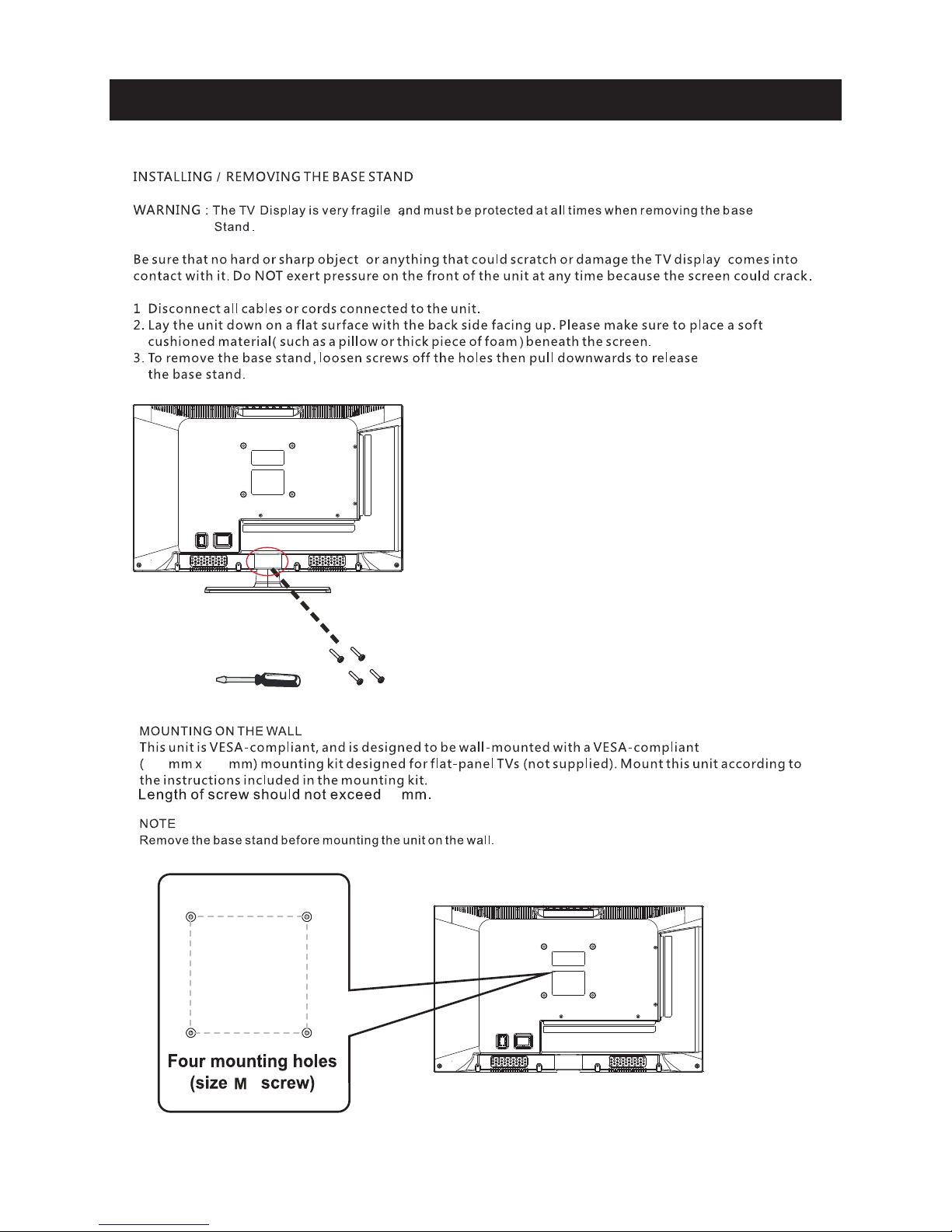
Caution
Important Safety Precautions
Top/Side panel diagram
Remote Controller
Battery Installation
Using the Remote Control
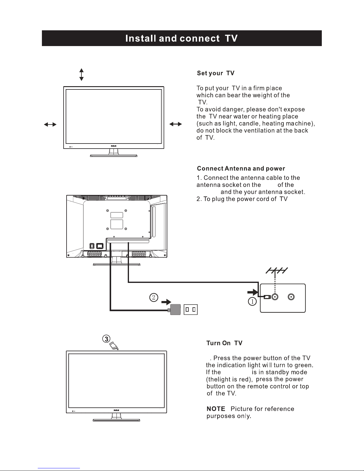
Install TV
Set your TV
Connect Antenna and power
Turn On TV
Help
2
3
4
6-7
8
9
12
13-29
30
31
TV Bracket assembly
5
Specifications
Select Input Source
Wall Mount Installation
Picture Menu
Audio Menu
Channel Menu
Parental Menu
Setup Menu
13-15
16-17
18-20
21-25
26-29
Systems Connection
10
The light eni ng flas h wit h arr owhea d sym bol , withi n an eq uilatera l tri angle is
inte nde d to al ert the u ser t o the presen ce of u n-insula ted " dangerou s vol tage"
with in th e pro ducts e ncl osu re that m ay be o f s uffic ien t magnitud e to co nstitute a
risk o f ele ctr ic shoc k to th e persons.
The ex cla mat ion poi nt wi thi n an equi lat eral trian gle i s intend to al ert t he user to
the prese nce o f impor tan t operatin g and m aintenan ce (s ervicing ) ins truction s in
the liter atu re acco mpa nyi ng the ap pli ance.
Co r r e ct dis posa l of th is Pr o duct
W aste Ele ctr ical & Elect ron ic Equipme nt (W EEE)
Your pro duc t is designe d and m anufactu red w ith high qua lit y material s and
comp one nts w hich ca n be re cyc led and r eus ed.
This s ymb ol me ans tha t ele ctrical an d ele ctronic eq uip ment, at the ir en d-of-lif e,
should be d isp osed of s epa rat ely fro m you r househol d was te.
Please di spo se of thi s equ ipm ent at yo ur lo cal commun ity w aste
collect ion /recy cli ng centre.
In the E uro pea n Union t her e are s epara te co llection s yst ems for used e lec trical
and elect ron ic prod uct s. Please he lp us t o conserve t he en vironmen t we li ve in!
Caution
2
3
4
8
3.95”
3.95”
4
3.95 ” x 3. 95”
100 100
Wall Mount Installation
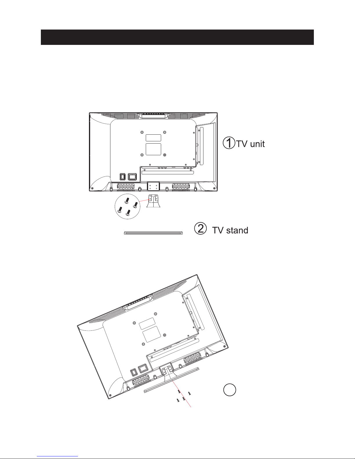
1.Match the TV unit into the stand, then hold the TV stand,
revolve and lock the tv unit tightly as the arrowhead point.
2.Fix the screws into the TV stand after installing the tv
unit and tv stand.
3
screws
TV Bracket assembly
5
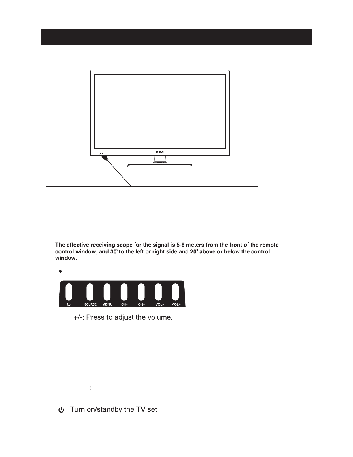
Indicator on(Red) Standby mode
Indicator on(Green) Power on mode
(IR) Infrared Receiver: Receives IR signals from the remote control.
(Power on/Standby) LED Indicator: Press
to turn on and off
VOL
The functions of the buttons on the are as follows:TV
CH+/-:When watching TV: select channels.
MENU:
1.Press Menu.
2.Press SOURCE to enter.
3.Use CH+/- to shift UP/DOWN.
4.Press SOURCE to confirm, then press VOL+/-to adjust.
5.Press SOURCE to confirm
Top panel diagram
6
SOURCE External signal input selection and confirm the
item selected.
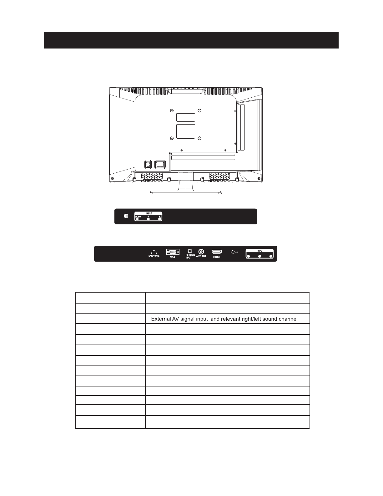
Side Panel Diagram
7
(Left Side)
(Back Side)
COAX IAL
Y Pb Pr
Serv ice Port
Conne ct to ANT or ca ble source
PC AUDIO IN
PC audio input
VGA IN
VGA signal from computer output
YPbPr
Connect to the composite terminal of your DVD/VCR
ANT 75 Ω
EARPHON E
For Upgra de Us e
AV INPUT
Earp hon e out put
COAXIAL
Digital Au dio O utput
Service Port
HDMI IN
Connect to HDMI of DVD or other equipment
Name
Function Description
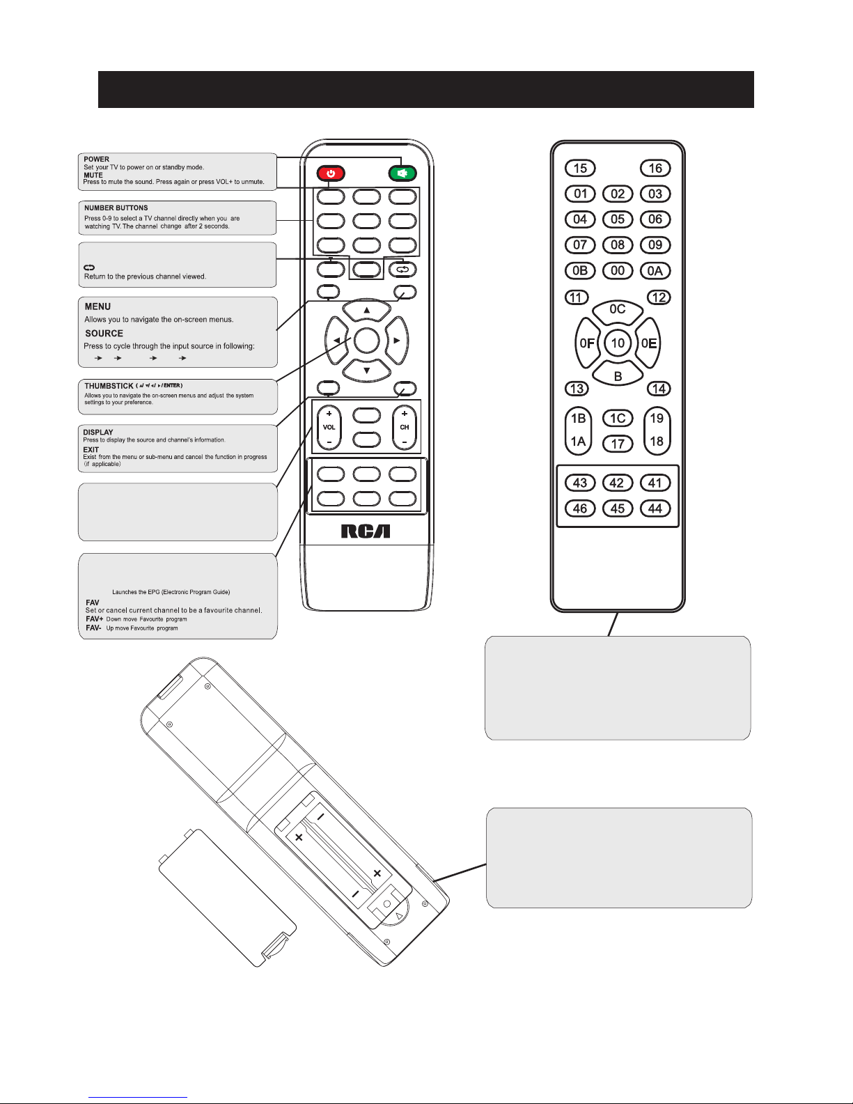
S.MODE: Press to cycle through the different sound settings
P.MODE: Press to cycle through the different picture settings
CH +/ - : Press to scan thr ough or to selec t a chann el.
V +/- : Press to increa se / decr ease t he soun d level .
Pres s "-" to ent er a pr ogram numb er fo r mult iple pr ogram
chan nel, su ch as 2- 1 etc.
SLEEP: Select amount of time before TV turn
off
automatically.
MTS:
Pres s to sel ect the au dio mode ,yo u can sel ect ster eo,
Mon o,or SAP( seco nd audi o prog ram).
GUIDE:
1
5
9
2
6
0
3
7
4
8
ENTER
MENU
SOURCE
EXIT DISPLAY
P.
MODE
S.
MODE
SLEEP MTS GUIDE
FAV FAV- FAV+
Univers al re mot e cod e
This is the c ode f or re mot e control of
RLED244 5A- B,i f you w ant to change to a
univers al re mot e con trol,you can ed it
this code i nto y our u niv ersal remote co ntr ol.
(1)O pen t he batt ery c ompar tme nt cove r
on the b ack s ide
(2)I nse rt two 1. 5V ba tteri es of AA A type
with c orr ect pol ari ty
(3)C los e the bat ter y compa rtm ent cov er
on the b ack s ide
Universal Remote Control code:007F
(Universal Remote control is not included)
Remote Controller
8
TV AV YP bP r HDM I PC
3
side
indicator
9
10cm
10cm 10cm
LED TV
 Loading...