

Page 1
i
Important Safeguards
IMPORTANT SAFETY INSTRUCTIONS
1. Read all the safety and operating instructions before the television is operated.
2. Retain the safety and operating instructions for future reference.
3. Adhere to all warnings on the television and in the operating instructions.
4. Follow all operating and use instructions.
5. Do not use this apparatus near water.
6. Clean only with dry cloth.
7. Do not block any ventilation openings. Install in accordance with the
manufacturer’s instructions.
8. Do not install near any heat sources such as radiators, heat registers, stoves,
or other apparatus (including amplifiers) that produce heat.
9. Do not defeat the safety purpose of the polarized or grounding-type plug. A
polarized plug has two blades with one wider than the other. A grounding type
plug has two blades and a third grounding prong. The wide blade or the third
prong is provided for your safety. If the provided plug does not fit into your
outlet, consult an electrician for replacement of the obsolete outlet.
10. Protect the power cord from being walked on or pinched particularly at plugs,
convenience receptacles, and the point where they exit from the apparatus.
11. Only use attachments/accessories specified by the manufacturer.
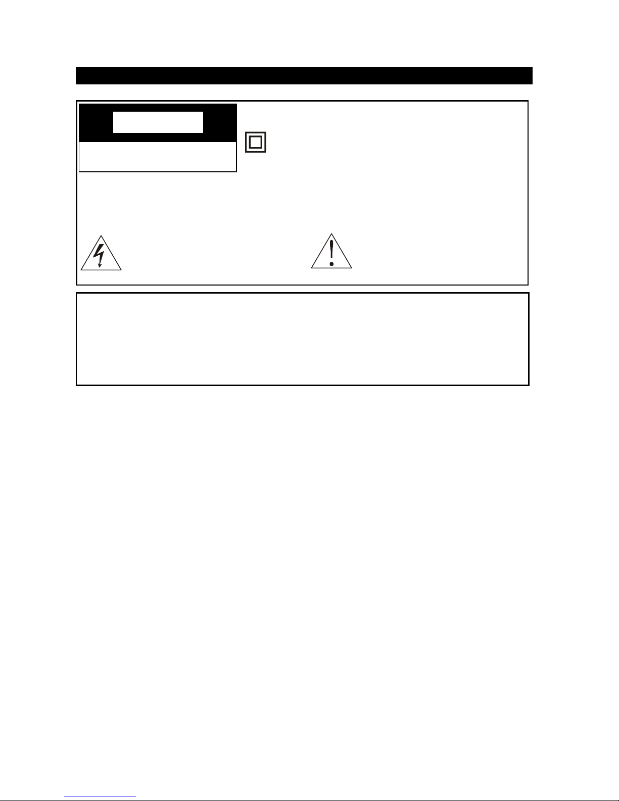
This symbol indicates “dangerous voltage” inside the product
that presents a risk of electric
shock or personal injury.
This symbol indicates important instructions accompanying
the product.
WARNING
To reduce the risk of fire or electric shock, do not expose this product to rain or
moisture.
The apparatus must not be exposed to dripping or splashing. Objects filled with
liquids, such vases or drinking glasses, must never be placed on the apparatus.
CACA
CACA
CA
UTIONUTION
UTIONUTION
UTION
RISK OF ELECTRIC SHOCK
DO NOT OPEN
This symbol indicates that this product incorporates double insulation between hazardous
mains voltage and user accessible parts. When
servicing use only identical replacement parts.
Caution: To reduce the risk of electric shock, do not remove cover (or back). No
user serviceable parts inside. Refer servicing to qualified service
personnel.
Page 2
2ii
Important Safeguards
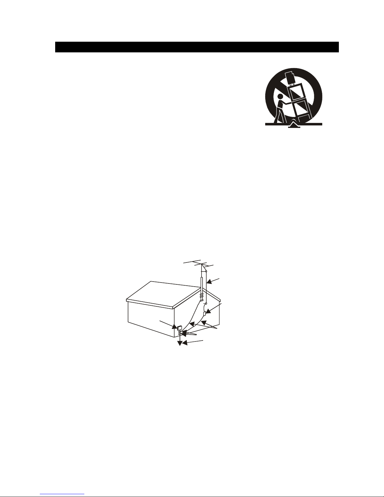
12. Use only with the cart, stand, tripod, bracket, or table
specified by the manufacturer, or sold with the
apparatus. When a cart is used, use caution when
moving the cart/apparatus combination to avoid injury from tip-over.
13. Unplug this apparatus during lightning storms or
when unused for long periods of time.
14. Refer all servicing to qualified service personnel.
Servicing is required when the apparatus has been damaged in any way, such
as power-supply cord or plug is damaged, liquid has been spilled or objects
have fallen into the apparatus, the apparatus has been exposed to rain or
moisture, does not operate normally, or has been dropped.
15. If an outside antenna or cable system is connected to the product, be sure the
antenna or cable system is grounded so as to provide some protection against
voltage surges and built-up static charges. Section 810 of the National Electrical
Code, ANSI/NFPA No. 70-1984 (Section 54 of Canadian Electrical Code, Part 1)
provides information with respect to proper grounding of the mast and supporting structure, grounding of the lead-in wire to an antenna-discharge unit, size of
grounding conductors, location of antenna-discharge unit, connection to grounding electrode. See following example.
16. Mains plug is used as the disconnect device. It shall remain readily operable
and should not be obstructed during intended use.
ELECTRIC
SERV ICE
EQUIPMENT
NEC-NATIONAL ELECTRICALCODE
POWER SERVICE GROUNDING
ELEC TRODE SYSTEM
(NEC AR T 250 PART H)
GROUND CLAMPS
GROUNDING CONDUCTOR
S
(NEC SECTION 810-21)
ANTENNA
DISCH ARGE UNIN T
(NEC SECTION 810-21)
ANTENNA
LEAD IN
WIRE
Page 3

3
Contents
Overview 4
External connection 6
Remote control 8
Basic operation 10
Menu Basic operation 12
Using the PICTURE menu 12
Using the SOUND menu 13
Using the TUNING menu 14
Using the FUNCTION menu 15
Picture defects and countermeasures (AIR reception) 18
Troubleshooting 19
Appendix
Color TV receiving systems table 20
Color TV Functions table 21
Color TV Specifications table 22
Color TV Dimensions and Weights table 23
Color TV Accessories table 24
Remote Control 24
You are welcome to use RCA color TV
Thank you for your purchasing RCA color TV product which adopts English display, we hope
RCA TV brings you new pleasure in your audio and visual entertainment. To enjoy the various
functions offered by the unit, please read this manual thoroughly before using the unit.
Page 4
4
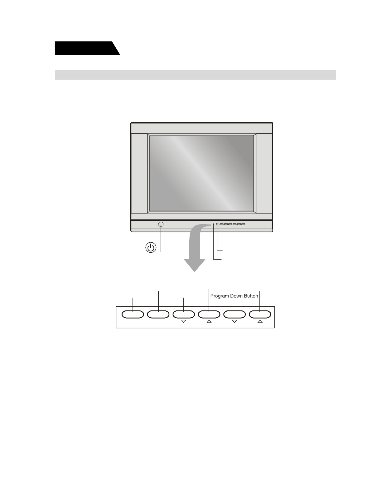
Overview of the function keys
Dear customer, please observe the function keys on the TV and refer to the following
diagram to learn every function key.
Overview
TV/AV MENU VOL PROG
POWER SWITCH
POWER INDICATOR
IR RECEIVER WINDOW
TV/AV Button
Menu Button
Vol ume Down Button
Program Up Butto
n
Vol ume Up Button
Page 5
5
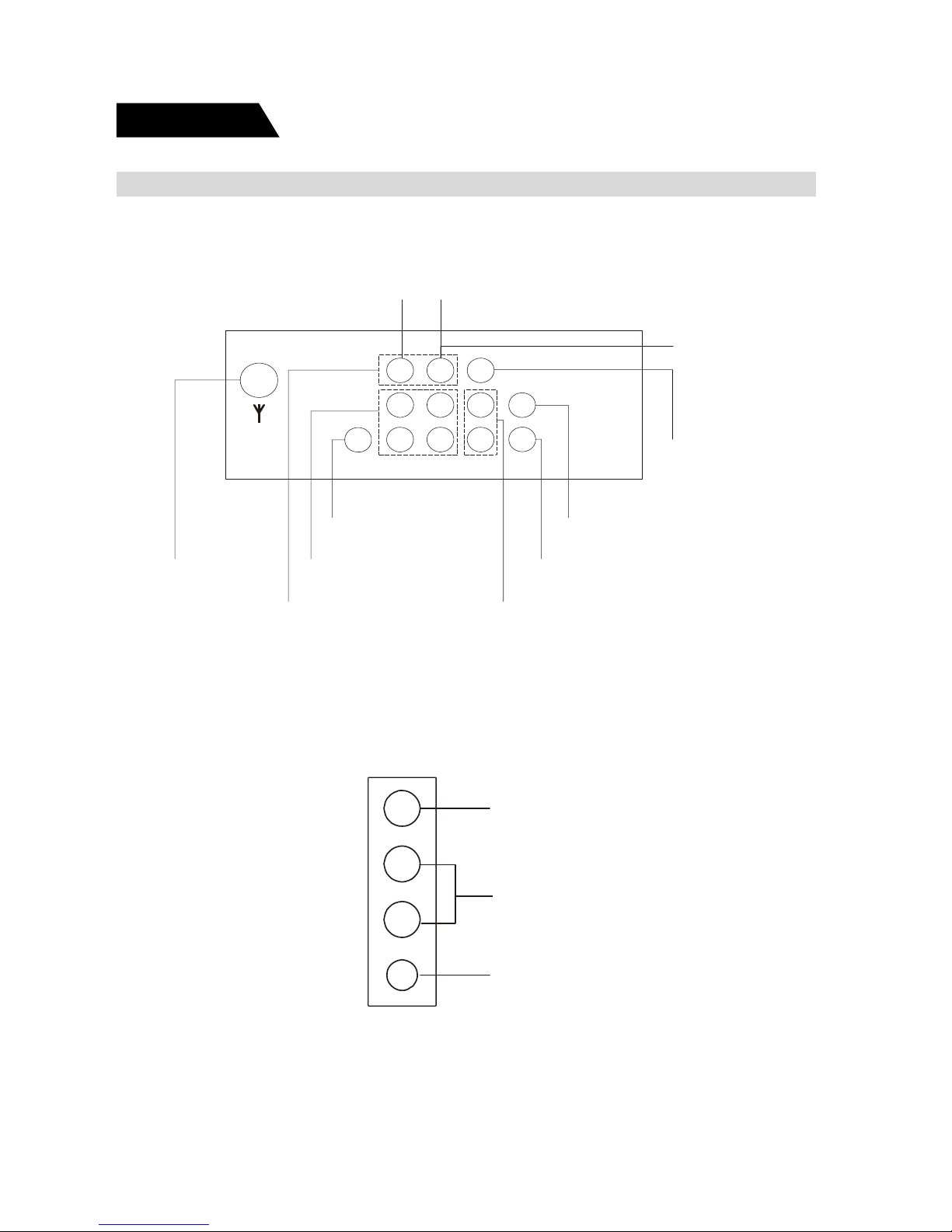
VIDEO INPUT
AUDIO INPUT
HEADPHONE OUTPUT JACK
L
R
Overview
Overview of the back AV jacks
Please observe the AV jacks on the back of TV, and refer to the following diagram
to learn the function of every AV jack.
Side AV and Headphone jacks
Please sure whether your TV has side AV and headphone jacks, if it has, please
refer to the following diagram to learn the function of every side jack.
Antenna Jack
Video
Input Jack
Audio
Input Jack
C
Input Jack
r
SVHS
Input Jack
Audio
Output Jack
Video
Output Jac
k
C
Input Jack
b
Y Input Jac
k
AV1
AV2
Page 6
6
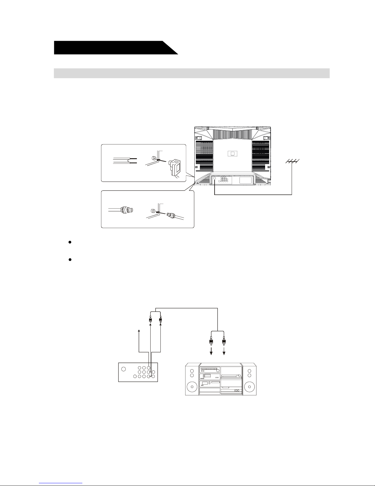
Antenna connection
The antenna input impedance used in this model is 75ohm, just connect 75ohm coaxial cable of VHF/UHF antenna to the antenna jack on the back of TV directely. If you
use 300 flat feeder, you need connect it with one 300 /75ohm converter first, then
connect the converter into the antenna jack.
Note:
It is recommended to use 75ohm coaxial cable to eliminate interference and
noise caused by radio wave.
Do not bind the antenna cable and power cord together.
Connect to Audio equipment
Connect this unit with the audio input terminal (pinhole) of a stereo system, then you
may enjoy quality sound at the same time of enjoying quality picture.
External connection
(White) (Red)
(
White) (Red)
VIDEO OUTPUT
L AUDIO OUTPUT
R AUDIO OU TPUT
To external equi pment input
Stereo System
Page 7
7
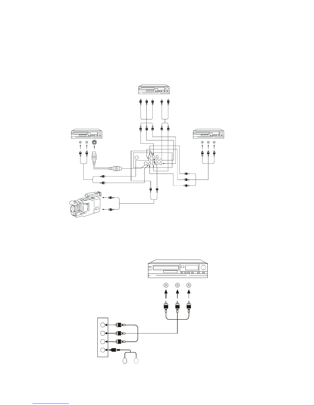
If your model has side A V jacks or headphone jack, please connect as the following figure shown:
To AUDIO output (Red)To VIDEO output (Yellow)(White
)
VTR without S-VIDEO
(Red)
(White)
(Yellow)
Headphone
Connect to video equipment (VCD, DVD) and headphone jack
Connect back AV jacks as the following figure shown:
S-terminal has the same AUDIO IN jack as AV1, but you can not input AV signal from
these two terminals at the same time. YUV has the same AUDIO IN jack as AV2,
but you can not input AV signal from these two terminals at the same time.
VTR with Y Cb Cr terminal
、、
VTR with S-VIDEO termin al
(yellow) To Video output
To Video output (yellow)
To Audio output(red)
(yellow)
(white)
(red)
(white) T o Audio output
(yellow)
(white)
(white)
To S-VIDEO output
T o Audio output(red)
(white)
(white)
(red)
TO SVHS socket
VTR without S-VIDEO terminal
(Green) To Y output
(blue) To Cb output
(red) To Cr output
To Audio output (red)
(Green)
(blue)
(red)
(red)
(white)
(white)
Page 8

8
Remote control
Remote control
Mute button Lowers the volume to its minimum level.Press again to
restore volume.
ON/OFF Turns the TV on and off.
0-9(Number buttons) Enter channel numbers and time settings directly through
the remote control.
DISPLA Y Displays channel information.
PRE.CH Returns you to the previous channel. If the user is in the
menu system, PRE.CH will take the user to the previous
menu screen.
Mute
Power on/standb
y
Previous channel
Picture
TV/AV
Stereo
Game
Main menu
Volume u
p
/menu value u
p
Program down/menu select
Sleep
Browse
Clear
Sound
Ccd
Volume down/menu
Value down
Program up/Menu select
Digital, letter
Input buttons
Calendar
Display
Page 9

9
Remote control
Remote control
BROWSE “Browse” feature. Pressing the button twice will begin chan-
nel scan, again will stop at current channel.
SLEEP Set the sleep timer.
PICTURE Steps through picture presets MEMORY,STANDARD,DY-
NAMIC and MILD.
CLEAR Removes any menu or display from the screen and re-
turns you to TV reviewing. For menu with digit inputs, pressing CLEAR button will clear all number entered.
TV/A V Toggles the set between available AV inputs and RF input.
MENU Displays the TV’s main menu.
VOL (left and right)buttons Decrease or increase the TV’s volume, or move through
the on-screen menu system.
PROG.(up and down)buttons Scan up or down through the current channel list.
Press once to change the channel up or down; press and
hold to continue changing channels,or move through the
on-screen menu system.
SOUND Four preset audio settings for you to select (MEMORY/ST AN-
DARD/NEWS/MUSIC).
STEREO Four available audio modes (AUTO/MONO/STEREO/SAP)
CCD Turns on or turns off the closed caption.
Loading batteries: Remove the lid of the battery compartment, insert 2 size
AAA batteries with the polarities as indicated inside the compartment then replace
the lid.
Note:
1. One loading of batteries will last 1 year under normal use.
2. If you do not intend to use the remote control for a long period of time,remove
them to avoid damage due to leakage.
Page 10

10
Basic operation
Overview
Connect to the mains
Insert the mains wire plug of the unit into mains outlet.
Power on/off
Press the ON/OFF switch button to enter standby status or turn on TV.
Note: The power indicator will turn into red when TV is under standby state.
The power indicator will die when TV is under turn on state.
Non-signal power-off in 5 minutes
In case the unit under blue screen or non-signal screen saver state, TV will be
standby state automatically 5 minutes later, to turn it on, please press power button
on TV.
Change channels
You can change channels by using the PROG
/ button in front of the TV(or the CH
/ button on the remote control).
V olume UP/DOWN
You can adjust the sound by using VOL
/ button in front of the TV (or the VOL /
button on the remote control).
Sleep function
1. Press down SLEEP button on the remote control to display the preset time 120
minutes, 90 minutes, 60 minutes, 30 minutes, the unit will be automatically
turned off when the set time has elapsed.
2. To cancel the time-off function, press the SLEEP button consecutively until dis-
play changes to SLEEP OFF state.
Picture modes
Press PICTURE button on the remote control to select picture modes (MEMORY—
STANDARD—DYNAMIC—MILD), MEMORY status is the picture mode you have
adjusted.
Page 11

11
Sound modes
Press SOUND button on the remote control to select sound modes (MEMORY—STANDARD—NEWS—MUSIC), MEMORY status is the sound mode you have
adjusted.
Calendar
Press CALENDAR button to display the screen as the figure shown:
The calendar of these series models provides you searching the solar calendar and
current week from January 1, 1900 to December 31, 2049. Press PROG
/ buttons
to move to the year, month, date, then Use VOL
/ buttons to adjust the data of the
year, month, date. Press CALENDAR button to exit. The date inquiry is the same
steps as above.
GAME
You and TV place black and white stones on a large ruled board alternatively. If a
black or white stone is put between black stones or white stones, then white stones
or black stones located between the same color stones will be taken away. When
one player gets all stones, or fills in all eyes, the game is end. If you get more stones
than TV’s, you win. Press GAME button to display the screen as the figure shown:
Use CH
/ buttons to move upward or downward and VOL / buttons to left or
right, then press MENU button to confirm. Press GAME button to exit.
Basic operation
Overview
Page 12

12
Using the PICTURE menu
BRIGHTNESS Adjust left/right to darken/brighten the picture. Adjust range:
(00~63).
CONTRAST Adjust the difference between the light and dark areas of the
picture. Adjust range: (00~63).
COLOR Adjust left/right to decrease/increase color intensity or saturation.
Adjust range: (00~63).
1. To enter the menu, press MENU button in front of the TV (or on the remote control),
press MENU button in front of TV (or on the remote control) again to select the
icon.
2. Press PROG
/ button in front of TV ( or the CH / button on the remote
control). ) to select the item you want to change.
3. Use VOL
/ button in front of TV (or VOL / button on the remote control) to
change the setting.
4. To exit the menu, press MENU button in front of TV (or on the remote control) to
cycle all of icons one time in the previous menu. You can press menu button on
the remote control to exit the menu operation directly.
Menu basic operation
Menu basic operation
Using the PICTURE menu
PICTURE
BRIGHTNESS
SHARPNESS
COLOR TEMP NORMAL
COMB FILTER ON
Page 13

13
Using the PICTURE menu
Using the PICTURE menu
SHARPNESS Adjust left/right to soften/sharpen the picture detail. Adjust range:
(00~63).
TINT Adjust the balance between the red and green levels. Adjust
range: (-31~+31).
COLOR TEMP Automatic color adjustments. Provide three states: (NORMAL,
WARM, COLD).
COMB FILTER Adjust the comb filter on or off. (Optional item, please check your
television has this function.) Provide two states:(ON,OFF)
VOLUME Adjust left/right to change small/large sound. Adjust range: (00~63).
TREBLE Adjust left/right to decrease/increase high pitched sound. Adjust range:
(00~63).
Using the SOUND menu
Using the SOUND menu
SOUND
Page 14

14
BASS Adjust left/right to decrease/increase low pitched sound. Adjust range:
(00~63).
BALANCE Adjust left/right to emphasize left/right speaker balances. Adjust range:
(-31~+31).
SURROUND Adjust different kinds of the surround sound effect. Provide two states
(OFF, ON).
STEREO Adjust different kinds of the stereo sound effect. Provide three states:
(P ASS, PSEU, MONO ).
Using the SOUND menu
Using the SOUND menu
Using the TUNING menu
Using the TUNING menu
CHANNEL Use VOL / button in front of TV (or VOL / button on the remote
control) to select channels, or enter the channel number directly using
the number buttons.
DELETE CH Select Yes to skip the channels above. Select NO to go into the chan-
nel above. Provide two states:(YES,NO).
Page 15

15
Using the TUNING menu
Using the TUNING menu
SOURCE Let you select AIR or CABLE. Select AIR to receive radio broadcast
signal. Select CABLE to receive CATV signal. Provide two states:(AIR,
CABLE)
BTSC Available audio modes, provide four states: AUTO, MONO, STEREO,
SAP
AUTO SEARCH Press VOL button in front of TV (or VOL button on the remote
control) to start channel searching and store automatically.
LANGUAGE Select from available language to display all menus.
SCREEN Turn on or off the background function when no signal is received.
Provide three states: (OFF, BLUE BACK, SAVER).
CHILD LOCK Input four digital number on the remote control, you may change the
child lock states(ON or OFF), if input the right password, the child lock
will take effect when the TV turns on next time.
The initial password is MUTE+999.
Using the FUNCTION menu
Using the FUNCTION menu
LANGUAGE ENGLISH
SCREEN SAVER
CHILD LOCK
CCD OFF
V-CHIP
FUNCTION
Page 16

16
Using the FUNCTION menu
V-CHIP Adjust V-CHIP function on or off, provide two states: (ON, OFF).
V-CHIP Press VOL button in front of TV (or VOL button on the remote
control) to see the figure below.
CONFIRM PASSWORD: Press four digital buttons on the remote control, V-CHIP
menu can not be displayed without inputting the right password. The initial password is 0358.
MP AA Press VOL or VOL buttons on the remote control to select the MPAA
ratings. When select a movie rating, the system will automatically block
all other movies with higher ratings.
CCD Offers eight closed captioned modes including four text modes. Pro-
vide nine states:(OFF,C1,C2,C3,C4,T1.T2,T3,T4).
V-CHIP
V-CHIP [ON]
MPAA: [N/R]
TVPG SETTING
RETURN
Page 17

17
Hierarchy of Age-Based Ratings
TV-Y
All Children
TV-Y7
Directed to Children 7 years and older
TV-G
General Audie nce
TV-PG
Parental Guidance Suggested
TV-14
Parents Strongly Cautioned
TV-MA
Mature Audience Only
TVPG SETTING Press VOL or VOL button on the remote control to go to the
TVPG setting.
RETURN Come back the higher menu.
N/R
G
PG
PG-13
NC-17
R
X
All Children
Parental Guidance
No one under 13 admitted
No one under 17 admitted
Mature audience only
Restricted
No de f i ne
Hierarchy of MPAA RATINGS
Page 18

18
The most common types of television interference are as follows:
SNOWY PICTURE
Snowy picture is usually due to weak signal. Adjust antenna or install an antenna amplifier.
DOUBLE IMAGE OR “GHOSTS”
Double images are usually caused by reflections from
tall buildings. Adjust the direction of the antenna or raise
it.
RADIO WAVE INTERFERENCE
Wavy patterns are moving on the screen, which are
usually caused by nearby radio transmitters or shortwave receiving equipment.
HIGH TEMPERATURE ELECTROTHERMAL INTERFERENCE
Diagonal or herringbone patterns appear on the screen
or part of picture is missing. This is probably caused by
high temperature electrothermal equipment in a nearby
hospital.
NOTE:If one of these symptoms appears on the screen
when the cable from a company is connected,
this may be due to the local cable company
broadcast.
Picture defects and countermeasures(VHF/UHF reception)
Picture defects and countermeasures (AIR reception)
Page 19

19
If you have any problem, check the countermeasures for each symptom listed below.
The following symptoms may have been caused by inappropriate adjustments rather
than actual malfunction of the unit.
If the trouble persists, contact the service center.
Troubleshooting
Page 20

20
Appendix 3
Color TV Specifications table
ledoM
dnuoS
)W(tuptuO
)V(ylppusrewoP
lortnoCetomeR
)V(seirettaB
rewoPdetaR
noitpmusnoC
)W(
2072RCR
2*W4 V021:C 2A *V5.1 051
Appendix 2
Color TV Functions table
1VA 2VA
VA
TUO
/EDIS
TNORF
VA
rCbCY SHVS
-PDAEH
ENOH
DCC PIHC-V
--DLIHC
KCOL
BMOC
RETLIF
CSTB
VA
OERETS
2072RCR
√ √ √ √ √ √ √ √ √ √ √ √ √
Functions
MODEL
V VT A
LAP CSTN MACES LAP 85.3CSTN 34.4CSTN MACES M,LAP N,LAP
0
6LAP
K/D I G/B M K/D G/B 'L,L zH05 zH06 zH06 zH05 zH06 zH05 zH06
2072RCR
Appendix 1
Color TV receiving systems table
SYSTEM
MODEL
√ √
Page 21

21
Appendix 4
Color TV Dimensions and Weights table
ledo HM XDXW:)HC(snoisnemi )D sbl(thgieW
2072RCR
"4.22X"7.91X"5.9 62 .29
Appendix 5
Color TV Accessories
launams'resu
etomeR
lortnoc
seirettaB annetnA
ytnarraW
drac
2072RCR
√ √
ACCESSORIES
MODEL
Remote controller
Transmission system: Infrared
Controlling range: 8.5m
Controlling angle: 30° (Horizontal)
Batteries: Size AAA 1.5V´2
Note:
Due to TV may be used with different CRT tube, weight marked in this user's manual or in
packaging box are subject to change without notice.
Page 22

39034100
Page 23

1645837B_20F510TD_Cvr.indd 1 7/22/05 5:51:20 PM
 Loading...