

Page 1
Assembly Instructions for
Stand Model RB3600
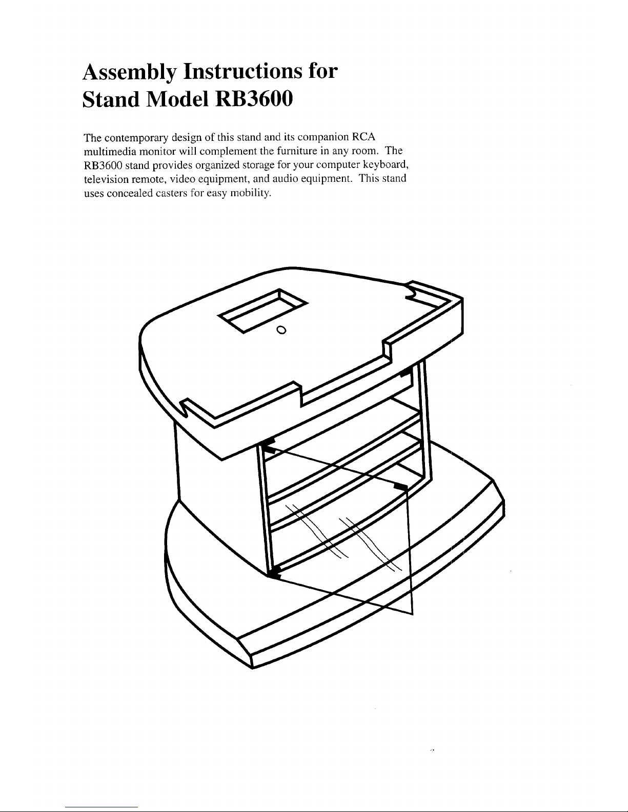
The contemporary design of this stand and its companion RCA
multimedia monitor will complement the furniture in any room. The
RB3600 stand provides organized storage for your computer keyboard,
television remote, video equipment, and audio equipment. This stand
uses concealed casters for easy mobility.
Page 2
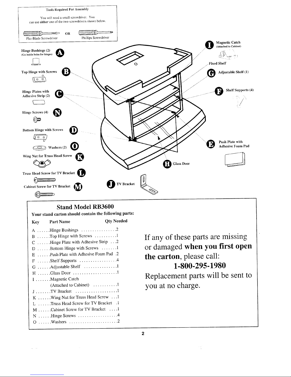
Tools Required For Assembly
You will need a small screwdriver, You
can use either one of the two screwdrivers shown below,
OR
FlaE-Blade Screwdriver
Phillips Screwdriver
Hinge Bushings (2) O(Go inside holes for blnges)
Top Hinge with Screws O
Hinge Plates with
Adhe:dve Strip (2)
Hinge.Screws (4) O
Bottom Hinge with Screws @
Washers (2)
Win E Nut for Truss Head Screw O
Truss Head Screw for TV Bracket O
Cabinet Screw for TV Bracket _.I
O
TV Bracket
O Magnetic Catch
• (Attached to Cabinet)
/
/ Fixed Shelf
/
/O Adjustable Sheff (1)
//
Shelf Supports (4)
\\
"-_ Push Plate with
Adhesive Foam Pad
Stand Model RB3600
Your stand carton should contain the following parts:
Key Part Name Qty Needed
A ...... Hinge Bushings ................ 2
B ...... Top Hinge with Screws .......... 1
C ...... Hinge Plate with Adhesive Strip ...2
D ...... Bottom Hinge, with Screws ....... 1
E ...... Push Plate with Adhesive Foam Pad .2
F ...... Shelf Supports ................. 4
G ...... Adjustable Shelf ............... 1
H ...... Glass Door .................... 1
I ....... Magnetic Catch
(Attached to Cabinet) ........... 1
J ....... TV Bracket ................... 1
K ...... Wing Nut for Truss Head Screw ...1
L ...... Truss Head Screw for TV Bracket .1
M ...... Cabinet Screw for TV Bracket .... 1
N ...... Hinge Screw,,; .................. 4
O ...... Washers ...................... 2
If any of these parts are missing
or damaged when you first open
the carton, please call:
1-800-295-,1980
Replacement parts will be sent to
you at no charge.
Page 3

Your stand comes mostly assembled. All you need to do is insert the shelf into the stand and attach the glass
door. As you can see from the following instructions, completing your stand is a easy as (steps) one, two, three...
S t_..._1.
Insert the shelf in the stand
• Place the 4 shelf support pins (F) into the pre-drilled holes
inside the stand at your desired shelf height.
• Put the shelf(G) on the pins.
Attach the glass door
• Insert a bushing (A) into the hole in the inside bottom of
the sland. Place the pin of the bottom hinge (D) into this
bushi!ng (A).
• Peel the paper backing from the 2 hinge plates (C) and press
them on the inside of the glass door (H). Stick one along the
top, ,'md the other along the bottom.
• Slip _:he top hinge (B) over its hinge plate (C). (Make sure the
hinge, plate is under the hinge's screw holes.) Use 2 screws (N)
to secure the top hinge to the door. Do not overtighten the
screws.
• Now, slide the bottom hinge (D) over its hinge plate (C).*
(Make sure the hinge plate is under the hinge's screw holes.)
Use 2 screws (N) to secure the top hinge to the door. Do not
overtighten the screws.
• Insm* a bushing (A) into the hole on the inside top of the stand.
Slide the glass door (H) into position on the stand by inserting
the pin of the top hinge into this bushing (A). The bottom edge
of the glass should slide into the bottom hinge (D).
• Carefully close the door and inspect it. If necessary, you can
adjust the position of the glass door. Simply loosen the hinge
screws (N) slightly, slide the door into the desired position in
the hinges, and retighten the screws.
• Remove the paper backing from the touch plate's foam pad (E)
and place the pad over the top of the glass door. Position the
pad so it aligns with the touch latch. Then, press the touch
plate (E) over the pad.
* Because glass door sizes may differ slightly, two plastic
washers (O) are provided to raise the bottom hinge (D) and
keep it from rubbing against the stand base. Place the
washer(s) (O) under the bottom hinge (D) as shown in the
illustration below. Install the washer(s) (0) only if needed.
0
0
0
Page 4

Ste_p_33
_ecure your RCA multimedia monitor to the top of
the stand
(This stand is specifically designed for RCA
multimedia monitor model CM36702ET and
Compaq computer model 259600-001.)
(Safety Note : Two people are required for proper
placement of the RCA multimedia monitor on the
stand.)
• Position your monitor on the top of the stand so that the curve
of the bottom control panel fits into the curve in the top of the
stand.
• Remove the screw near the bottom of the monitor back cover
as shown in the drawing to the right. Replace this back cover
screw (S) with the cabinet screw (M) provided and attach the
TV bracket (J) to the monitor cabinet backcover.
• Using the truss head screw (L) and the wing nut (K), attach
the TV bracket (J) to the top of the stand through the bracket
hole and then to the pre-drilled hole (R). Do not overtighten
the screws.
TV/PC monitor back cover
O
Page 5

Additional Information About Positioning Components on Shelves
This stand is designed with ventilation openings which allow
adequate ventilation for components having a total power
consumption of not more than 690 watts. Total power
consumption can be determined by adding together the watts
of each component operating in this stand. Do not confuse
the output power rating (WATTS) per channel of an amplifier
with the power consumption. The power consumption of,
each component [given as WATTS (W)] can usually be found
on the back or bottom of each unit along with the brand name
and model number. Simply add the watts for each unit to get
the total power consumption. If equipment is installed that
uses more than 690 total watts, overheating may occur
resulting in a fire hazard or damage to your equipment.
To ensure the best performance fi'om your components,
follow these general guidelines when arranging them on the
shelves of your new sland.
• Amplifier/receivers, satellite rec'eivers, tuners, DVD players,
computers, and VCRs all generate heat during operation and
require sufficient clearance to prevent overheaing. Special
care should be taken when arranging these components in
your stand.
• The computer should be placed on the fixed shelf.
• An amplifier/receiver, generally produces more heat than
the other components. So, place it on the adjustable shelf
and be sure to leaw: at least the minimum clearance above
it based on the following power consumption: Watts rating
of the amplifier/receiver rated less than 350 Watt,¢-four
inches; for 350 to 650 Watts - six inches. Leave at least
two inches of clearance above all other components such as
VCRs, etc.
• Do not stack an amplifier/receiver and a VCR directly on
top of each other. Also do not stack other components
directly on top of an amplifier/receiver, satellite receiver,
DVD player, or VCR.
Page 6

Replacement Parts List - Model RB3600
If parts on your stand wear out from use or become
damaged, replacements can be purchased. The
replacement part listed here may be purchased from
your consumer electronics dealer or electronic parts
distributor. Please consult your Yellow Pages for the
name of the dealer or parts distributor nearest you.
Or, call 1-800-321-6993 (toll free in the U.S.A.) to see
if the part you need is available.
Key Part Name Stock No.
H ...... Glass Door ................ 238324
Thomson Consumer Electronics
10330 North Meridian Street
Indianapolis, IN 46290-1024
Printed on recycled paper
using soy-based ink
© 1997 Thomson Consumer Electronics, Inc.
Trademark(s) ® Registered
Marca(s) Registrada(s)
Printed in the U.S.A.
TOCOM 15250090
 Loading...