

Page 1
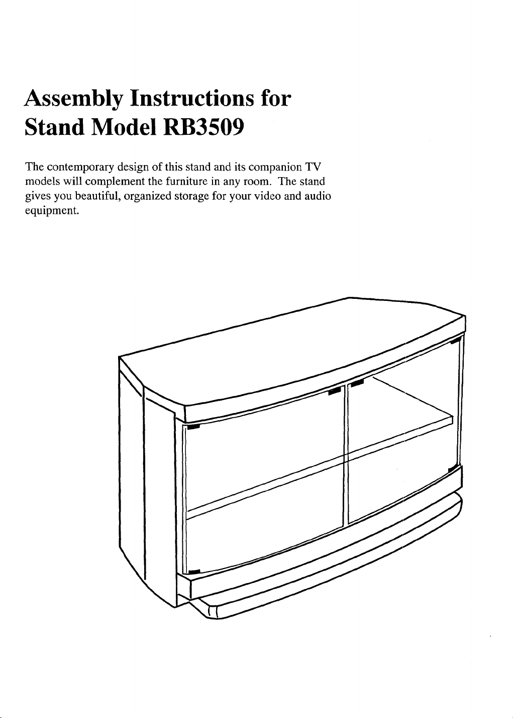
Assembly Instructions for
Stand Model RB3509
The contemporary design of this stand and its companion TV
models will complement the furniture in any room. The stand
gives you beautiful, organized storage for your video and audio
equipment.
\
\
Page 2
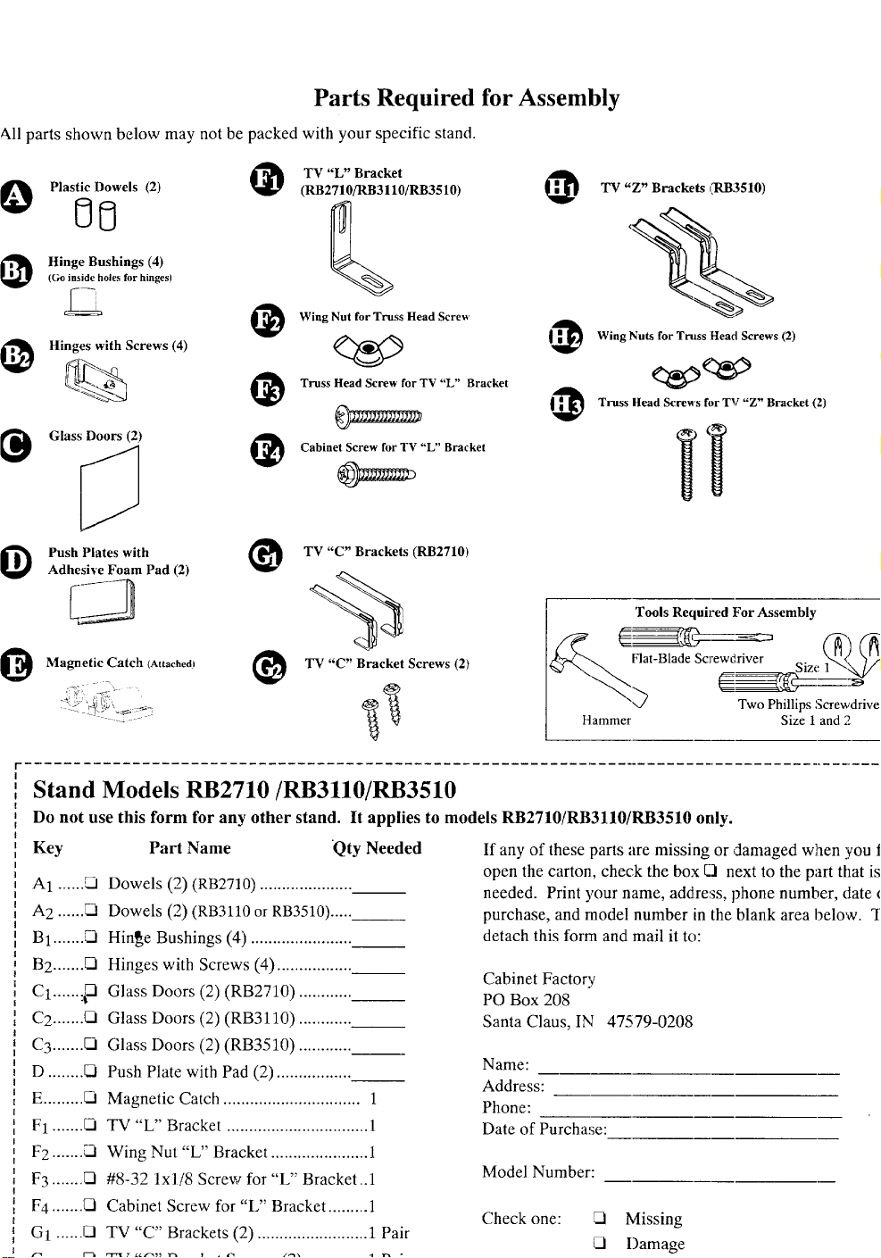
Parts Required for Assembly
All parts shown below may not be packed with your specific stand.
TV "L" Bracket
IO Plastic Dowels (2) (RB2710/RB3110/RB3510)
I_ Hinge Bushings (4)
(Go inside holes for hinges)
_ Wing Nut for Truss Head Screw'
Hinges with Screws (4)
I@ _ _ Truss Head Screw for TV "L" Bracket
I_ GlaSs DOOrs (2) _ Cabinet Screw for TV "L" Bracket
I_ Push Plateswith
Adhesive Foam Pad (2)
I_ Magnetic Calch (Attached_ _ TV "C" Bracket Screws (2)
TV "C" Brackets (RB2710)
@
TV "Z" Brackets kl_B3510)
Wing Nuts for Truss Head Screws (2)
@
Truss Head Screw's for TV "Z" Bracket (2)
Tools Required For Assembly
Flat-Blade Scre_river Size 1_" "7'._
Hammer Size 1 and2
Stand Models RB2710/RB3110/RB3510
Do not use this form for any other stand. It applies to models RB2710/RB3110/RB3510 only.
Key
A1 ...... ,_1
A2 ......
B1 .......
B2 ....... O
C1 ...... :_
C2 ....... 02i
C3 ....... _1
D ........
E......... _.1
F1 .......
F2 ....... _ Wing Nut "L" Bracket ...................... 1
F3 ....... _ #8-32 lxli8 Screw for "L" Bracket..1
F4 .......
G_ ...... O
Part Name Qty Needed
Dowels (2) (RB2710) .....................
Dowels (2) (RB3110 or RB3510) .....
Hinge Bushings (4) .......................
Hinges with Screws (4) .................
Glass Doors (2) (RB2710) ............
Glass Doors (2) (RB3110) ............
Glass Doors (2) (RB3510) ............
Push Plate with Pad (2) .................
Magnetic Catch ............................... 1
TV "L" Bracket ................................ 1
Cabinet Screw for "L" Bracket ......... ]
TV "C" Brackets (2) ......................... 1 Pair
If any of these parts are missing or damaged wlaen you fi
open the carton, check the box El next to the part that is
needed. Print your name, address, phone number, date o
purchase, and model number in the blank area below. TI
detach this form and mail it to:
Cabinet Factory
PO Box 208
Santa Claus, IN 47579-0208
Name:
Address:
Phone:
Date of Purchase:
Model Number:
Check one:
Missing
_l Damage
Two PhillipsScrewdriver
Page 3

Attaching and Adjusting Glass Doors
l. Hold the glass door up next to the stand to determine
where tile top hinge will be attached. You will repeat
steps 1 through 5 when attaching the opposite glass door.
Attach hinge to top side
of door with screw _.
toward inside,
i
Inside
Outside
Partially thread one screw into each of the
door hinges. Make sure the screw is
inserted through the holes in both the
hinge and the inside bracket. Then
attach the top hinge to the upper left
corner of the glass door. Gently tighten
the screw until the hinge is tight against
the glass. Do not attach the bottom hinge
to the door yet.
Bushing ._
3. Place one hinge bushing into each
of the two hinge holes in the stand.
If the fit is snug, tap them in with
a hammer.
If top bushing will not stay in
top hole, place it on top hinge.
4. Insert the top hinge of the glass door into the top bushi
(If the bushing is resting on top of the hinge, insert the
hinge and bushing into the top hole.) Insert the bottorc
hinge into bottom hinge bushi_ag and hold it in place w
sliding bottom of glass door irLto hinge. Then gently
tighten bottom hinge against the glass door.
First insert top hinge (attached
to glass] into top hole.
Then put bottom
hinge in hole and slide
glass door into the
bottom hinge, Gently
tighten screw.
The glass door should open and close easily without
rubbing on the stand. You can adjust the position of tt
glass door if necessary by slightly loosening the hinge
screws, moving the door, and then retightening the scr
5. Attach push plate to top edge of door where it contact_
magnetic catch already attached to the stand. First adt
the foam pad over the top of the door, and then slide p
plate over the pad.
Attach foam pad and push
plate where door contacts
magnetic catch.
If the bushing does not fit
securely in the top hole (falls
out), place it o_ the door over
the pin on the top hinge.
Page 4

Positioning and Securing TV on Top of Stand
This stand is used with different styles of'IV cabinets along with brackets. The TV cabinets are designed with areas on the
bottom and back of the cabinet that allow for placement of the TV on the stand. Your TV model determines where the plastic
dowels are placed and which brackets you will use. Follow the directions (A, B, or C) for your specific TV model. Two people
are required forproper placement of the 'IV on the stand.
Follow the directions below for models:
F35672MB F35751MB
F35731MB F35755MB
1. Insert the two plastic dowels into the holes shown in
Figure 1. Make sure the dowels are fully inserted
before placing the TV on the stand.
These dowels help
keep the TV in place.
"IV models designed
for this stand have
corresponding areas
in the bottom of their
cabinet that fit
around these dowels.
Figure I
2. Position the TV on the stand so that the molded areas
on the bottom of the TV slip over the dowels. *
3. Use the double brackets as shown in Figure 2 for
models:
F35731MB F35751MB
Use the single bracket as shown in Figure 3 for models:
F35672MB F35755MB
Single Bracket
TV
Screw
Figure 3
a. Align the holes in the single bracket (F1) with the holes
in the TV and top of the stand.
b. Insert the cabinet screw (F4) into the top of the bracket
(F1) and tighten.
c. Insert the truss head screw (F3) into the pre-drilled hole
from the bottom side of the stand and tighten with the
wing nut (F2).
Back of TV I
Figure 2
a.
Insert the long end of the brackets (G1) into the
round holes in the back of the TV.
b.
Insert the two screws (G2) through the brackets
(G1) and screw into the back of the stand.
* Step 2 requires a minimum of two adults.
Screws
4
Page 5

Additional Information About Positioning Components on Shelves
This stand is designed with ventilation openings which allow
adequate ventilation for components having a total power
consumption of not more than 135 watts. Total power
consumption can be determined by adding together the watts
of each component operating in this stand. Do not confuse
the output power rating (WATI'S) per channel of an amplifier
with the power consumption. The power consumption of
each component [given asWATTS (W)] can usually be found
,anthe back or bottom of each unit along with the brand name
and model number. Simply add the watts for each unit to get
the total power consumption. If equipment is installed that
uses more than 135 total watts, overheating may occur
resulting in a fire hazard or damage to your equipment. You
can remove the back cover for additional ventilation for
components with a total power consumption of not more than
475 watts.
Replacement Parts List - Models RB2710/RB3110/RB3510
The replacement parts listed here may be purchased
from your ProScan Consumer Electronics Dealer or
Premier Showcase Parts Distributor. Please consult
your Yellow Pages for the name of the Dealer or Parts
Distributor nearest you or call toll free in the U.S.A.
1-800-336-1900.
To ensure the best performance from your components,
follow these general guidelines when arranging them on the
shelves of your new stand.
• Amplifier/receivers, satellite receivers, tuners, and VCRs
all generate heat during operation and require sufficient
clearance to prevent overheating. Special care should be
taken when arranging these components in your stand.
• An amplifier/receiver, generally produces more heat than
the other components. So place it on the top shelf and be
sure to leave at least the minimum clearance above it based
on the following power consumption: Watts rating of the
amplifier/receiver rated less than 350 Watts -four inches;
for 350 to 650 Watts - six inches. Leave at least two inches
of clearance above all other components such as VCRs, etc.
• Do not stack an amplifier/receiver and a VCR directly on
top of each other. Also do not stack other components
directly on top of an amplifier/receiver, satellite receiver, or
VCR.
Key Part Name Stock No.
A1 ....Dowel (2/Pkg) (RB2710) ...................... 225553
A1 ....Dowel (2/Pkg) (RB3110/RB3510) ....... 225050
B1.....Hinges with Screws, (4) ........................ 225052
....... Bushings (come with B1)
C1.....Door, Glass (RB2710) ........................... 225554
C2..... Door, Glass (RB3110) ........................... 225555
C3.....Door, Glass (RB3510) ........................... 225556
D ...... Plate, Push w/pad ................................... 225051
E.......Catch, Magnetic .................................... 218886
F1.....TV "L" Bracket ..................................... 225055
F2 .....Wing Nut for "L" Bracket ..................... 218546
F3 .....#8-32 lxl/8 Screw for "L" Bracket ..... 218545
F4 .....Cabinet Screw for "L" Bracket ............. 225047
G1 ...."C" Brackets (2/Pkg) ............................. 225053
G2 ...."C" Bracket Screws (2/Pkg) .................. 225045
H1 ....."Z" Brackets (2/Pkg) .............................. 207894
H2 .....Wing Nuts for "Z" Brackets .................. 218546
H3 ....#8-32 lxl/8 Screws for"Z" Brackets....218545
Thomson Consumer Electronics
600 N Sherman Dr, PO Box 1976
Indianapolis, IN 46206-1976
_ rinted on recycled paper
using soy-based ink
©1994 Thomson Consumer Electronics, Inc.
Trademark(s) ® Registered
Marca(s) Registrada(s)
Printed in the U.S.A.
Part Number 1Q57 324-01A
 Loading...